EP4156152A1 - Dispositif d'affichage pliable - Google Patents
Dispositif d'affichage pliable Download PDFInfo
- Publication number
- EP4156152A1 EP4156152A1 EP20929689.6A EP20929689A EP4156152A1 EP 4156152 A1 EP4156152 A1 EP 4156152A1 EP 20929689 A EP20929689 A EP 20929689A EP 4156152 A1 EP4156152 A1 EP 4156152A1
- Authority
- EP
- European Patent Office
- Prior art keywords
- bending
- openings
- axis
- bending region
- display device
- Prior art date
- Legal status (The legal status is an assumption and is not a legal conclusion. Google has not performed a legal analysis and makes no representation as to the accuracy of the status listed.)
- Pending
Links
Images




Classifications
-
- G—PHYSICS
- G09—EDUCATION; CRYPTOGRAPHY; DISPLAY; ADVERTISING; SEALS
- G09F—DISPLAYING; ADVERTISING; SIGNS; LABELS OR NAME-PLATES; SEALS
- G09F9/00—Indicating arrangements for variable information in which the information is built-up on a support by selection or combination of individual elements
- G09F9/30—Indicating arrangements for variable information in which the information is built-up on a support by selection or combination of individual elements in which the desired character or characters are formed by combining individual elements
- G09F9/301—Indicating arrangements for variable information in which the information is built-up on a support by selection or combination of individual elements in which the desired character or characters are formed by combining individual elements flexible foldable or roll-able electronic displays, e.g. thin LCD, OLED
-
- G—PHYSICS
- G06—COMPUTING OR CALCULATING; COUNTING
- G06F—ELECTRIC DIGITAL DATA PROCESSING
- G06F1/00—Details not covered by groups G06F3/00 - G06F13/00 and G06F21/00
- G06F1/16—Constructional details or arrangements
- G06F1/1613—Constructional details or arrangements for portable computers
- G06F1/1615—Constructional details or arrangements for portable computers with several enclosures having relative motions, each enclosure supporting at least one I/O or computing function
- G06F1/1616—Constructional details or arrangements for portable computers with several enclosures having relative motions, each enclosure supporting at least one I/O or computing function with folding flat displays, e.g. laptop computers or notebooks having a clamshell configuration, with body parts pivoting to an open position around an axis parallel to the plane they define in closed position
-
- G—PHYSICS
- G06—COMPUTING OR CALCULATING; COUNTING
- G06F—ELECTRIC DIGITAL DATA PROCESSING
- G06F1/00—Details not covered by groups G06F3/00 - G06F13/00 and G06F21/00
- G06F1/16—Constructional details or arrangements
- G06F1/1613—Constructional details or arrangements for portable computers
- G06F1/1633—Constructional details or arrangements of portable computers not specific to the type of enclosures covered by groups G06F1/1615 - G06F1/1626
- G06F1/1637—Details related to the display arrangement, including those related to the mounting of the display in the housing
-
- G—PHYSICS
- G06—COMPUTING OR CALCULATING; COUNTING
- G06F—ELECTRIC DIGITAL DATA PROCESSING
- G06F1/00—Details not covered by groups G06F3/00 - G06F13/00 and G06F21/00
- G06F1/16—Constructional details or arrangements
- G06F1/1613—Constructional details or arrangements for portable computers
- G06F1/1633—Constructional details or arrangements of portable computers not specific to the type of enclosures covered by groups G06F1/1615 - G06F1/1626
- G06F1/1637—Details related to the display arrangement, including those related to the mounting of the display in the housing
- G06F1/1641—Details related to the display arrangement, including those related to the mounting of the display in the housing the display being formed by a plurality of foldable display components
-
- G—PHYSICS
- G06—COMPUTING OR CALCULATING; COUNTING
- G06F—ELECTRIC DIGITAL DATA PROCESSING
- G06F1/00—Details not covered by groups G06F3/00 - G06F13/00 and G06F21/00
- G06F1/16—Constructional details or arrangements
- G06F1/1613—Constructional details or arrangements for portable computers
- G06F1/1633—Constructional details or arrangements of portable computers not specific to the type of enclosures covered by groups G06F1/1615 - G06F1/1626
- G06F1/1637—Details related to the display arrangement, including those related to the mounting of the display in the housing
- G06F1/1652—Details related to the display arrangement, including those related to the mounting of the display in the housing the display being flexible, e.g. mimicking a sheet of paper, or rollable
-
- G—PHYSICS
- G06—COMPUTING OR CALCULATING; COUNTING
- G06F—ELECTRIC DIGITAL DATA PROCESSING
- G06F1/00—Details not covered by groups G06F3/00 - G06F13/00 and G06F21/00
- G06F1/16—Constructional details or arrangements
- G06F1/1613—Constructional details or arrangements for portable computers
- G06F1/1633—Constructional details or arrangements of portable computers not specific to the type of enclosures covered by groups G06F1/1615 - G06F1/1626
- G06F1/1684—Constructional details or arrangements related to integrated I/O peripherals not covered by groups G06F1/1635 - G06F1/1675
- G06F1/169—Constructional details or arrangements related to integrated I/O peripherals not covered by groups G06F1/1635 - G06F1/1675 the I/O peripheral being an integrated pointing device, e.g. trackball in the palm rest area, mini-joystick integrated between keyboard keys, touch pads or touch stripes
-
- G—PHYSICS
- G06—COMPUTING OR CALCULATING; COUNTING
- G06F—ELECTRIC DIGITAL DATA PROCESSING
- G06F2203/00—Indexing scheme relating to G06F3/00 - G06F3/048
- G06F2203/041—Indexing scheme relating to G06F3/041 - G06F3/045
- G06F2203/04102—Flexible digitiser, i.e. constructional details for allowing the whole digitising part of a device to be flexed or rolled like a sheet of paper
-
- Y—GENERAL TAGGING OF NEW TECHNOLOGICAL DEVELOPMENTS; GENERAL TAGGING OF CROSS-SECTIONAL TECHNOLOGIES SPANNING OVER SEVERAL SECTIONS OF THE IPC; TECHNICAL SUBJECTS COVERED BY FORMER USPC CROSS-REFERENCE ART COLLECTIONS [XRACs] AND DIGESTS
- Y02—TECHNOLOGIES OR APPLICATIONS FOR MITIGATION OR ADAPTATION AGAINST CLIMATE CHANGE
- Y02E—REDUCTION OF GREENHOUSE GAS [GHG] EMISSIONS, RELATED TO ENERGY GENERATION, TRANSMISSION OR DISTRIBUTION
- Y02E10/00—Energy generation through renewable energy sources
- Y02E10/50—Photovoltaic [PV] energy
- Y02E10/549—Organic PV cells
Definitions
- the present disclosure relates to the field of display technology, and more particularly, to a foldable display device.
- a metal sheet covering an entire surface of display panel and a supporting plate covering only a non-bending region of the display panel need to be respectively attached to a back side of the display panel, which not only increase difficulty of assembly and production costs, but also cause a step difference in the bending region of the display panel due to an incomplete coverage of the supporting plate, reducing flatness of the display device.
- An embodiment of the present disclosure provides a foldable display device which is configured to solve problems of poor flatness and difficulty in assembly of current foldable display devices.
- the embodiment of the present disclosure provides a foldable display device, comprising a front frame and a bottom frame assembly configured to fold the foldable display device into a folded state and an unfolded state.
- the foldable display device further comprises a display panel disposed between the front frame and the bottom frame assembly, and a supporting plate disposed between the display panel and the bottom frame assembly, wherein the supporting plate comprises a bending region and non-bending regions on both sides of the bending region, the bending region comprises a dummy bending axis, the bending region is provided with a plurality of openings, the openings comprise a dummy first long axis and a dummy first short axis, the first long axis coincides with or is parallel to the bending axis, the first short axis is perpendicular to the bending axis, and a distance between inner walls of both sides of the openings in a direction of the first long axis gradually decreases from both ends to middle of the openings along the direction of the first long
- the openings are arranged in an array in the bending region, and the openings in two adjacent columns are staggered along a direction perpendicular to the bending axis.
- an interval between the openings in one of the two adjacent columns of openings corresponds to the first short axis of the other column of the openings.
- the supporting plate is provided with a plurality of bending openings arranged at intervals, and the bending openings are formed by boundaries on opposite sides of the bending region respectively extending toward the bending region along a direction of the bending axis.
- the bending openings comprise a dummy second long axis and a dummy second short axis, the second long axis coincides with a direction of the first long axis of the opening in a same column, and a distance between inner walls of both sides of the bending openings extending along a direction of the second long axis gradually decreases from both ends to middle of the bending openings along the direction of the second long axis.
- an odd number of columns of openings are spaced between adjacent bending openings on a same side, and a distance between the openings at both ends in a column of openings adjacent to the bending openings and boundaries between both sides of the bending region is greater than a distance between the second short axis and the boundary of the bending region.
- the display panel comprises a panel bending region, and an orthographic projection region of the bending region of the supporting plate on the display panel covers the panel bending region.
- the bending region comprises a first bending region and a second bending region between the first bending region and the non-bending regions, the bending axis is located in the first bending region, and areas and/or densities of the openings in the first bending region and the second bending region are different.
- the area of the openings in the first bending region is greater than the area of the openings in the second bending region, and a density of the openings in the first bending region is less than a density of the openings in the second bending region.
- the area and density of each opening in the first bending region are equal, and the area and density of each opening in the second bending region are equal.
- a size of the openings gradually decreases, and the density of the openings gradually increases.
- the openings in the first bending region are blind holes, and openings of the blind holes are toward a side away from or close to the display panel.
- an elastic layer is disposed between the display panel and the supporting plate, and the elastic layer covers the supporting plate and fills the openings.
- the embodiment of the present disclosure further provides a foldable display device, comprising a front frame and a bottom frame assembly configured to fold the foldable display device into a folded state and an unfolded state.
- the foldable display device further comprises a display panel disposed between the front frame and the bottom frame assembly, and a supporting plate disposed between the display panel and the bottom frame assembly, wherein the supporting plate comprises a bending region and non-bending regions on both sides of the bending region, the bending region comprises a dummy bending axis, the bending region is provided with a plurality of openings arranged in an array, the openings comprise a dummy first long axis and a dummy first short axis, the first long axis coincides with or is parallel to the bending axis, the first short axis is perpendicular to the bending axis, a distance between inner walls of both sides of the openings in a direction of the first long axis gradually decreases from both ends to middle of the openings along the direction
- the supporting plate is provided with a plurality of bending openings arranged at intervals, and the bending openings are formed by boundaries on opposite sides of the bending region respectively extending toward the bending region along a direction of the bending axis.
- the bending openings comprise a dummy second long axis and a dummy second short axis, the second long axis coincides with a direction of the first long axis of the opening in a same column, and a distance between inner walls of both sides of the bending openings extending along a direction of the second long axis gradually decreases from both ends to middle of the bending openings along the direction of the second long axis.
- an odd number of columns of openings are spaced between adjacent bending openings on a same side, and a distance between the openings at both ends in a column of openings adjacent to the bending openings and boundaries between both sides of the bending region is greater than a distance between the second short axis and the boundary of the bending region.
- the embodiment of the present disclosure further provides a foldable display device, comprising a front frame and a bottom frame assembly configured to fold the foldable display device into a folded state and an unfolded state.
- the foldable display device further comprises a display panel disposed between the front frame and the bottom frame assembly, and a supporting plate disposed between the display panel and the bottom frame assembly, wherein the supporting plate comprises a bending region and non-bending regions on both sides of the bending region, the bending region comprises a dummy bending axis, the bending region is provided with a plurality of openings arranged in an array, a plurality of bending openings arranged at intervals are formed by boundaries on opposite sides of the bending region respectively extending toward the bending region along a direction of the bending axis, the openings comprise a dummy first long axis and a dummy first short axis, the first long axis coincides with or is parallel to the bending axis, the first short axis is perpendicular to
- the embodiment of the present disclosure further provides a foldable display device, by providing the plurality of openings in the bending region of the supporting plate, the distance between the inner walls of the both sides of the openings in the direction of the first long axis gradually decreases from the both ends of the openings to the middle along the direction of the first long axis.
- a portion with a short middle distance of the opening is easy to be stretched and widened, and has good extension performance and recovery ability, so that the supporting plate can be stretched and restored simultaneously with length change of the display panel during the bending process, thereby reducing stress and relative misalignment between the supporting plate and the display panel, and reducing a risk of film layers in the display panel from being separated.
- an integrated supporting plate can provide good support for various portions of the display panel to improve flatness of the display device and reduce difficulty in assembling the display panel with the front frame and bottom frame assembly.
- An embodiment of the present disclosure provides a foldable display device, which will be described in detail below with reference to FIGS. 1 to 10 .
- FIG. 1 is a schematic structural diagram of an entire foldable display device provided by an embodiment of the present disclosure.
- the foldable display device 100 comprises a front frame 1 and a bottom frame assembly 2 for folding thereof into a folded state and an unfolded state, and the foldable display device 100 further comprises a display panel 3 and a supporting plate 4.
- the front frame is configured to cover the display panel 3 and the bottom frame assembly 2
- the bottom frame assembly 2 is configured to carry the front frame 1, the display panel 3, and the supporting plate 4
- the display panel 3 is disposed between the front frame 1 and the bottom frame assembly 2
- the supporting plate 4 is disposed between the display panel 3 and the bottom frame assembly 2 and is located at a side of the display panel 3 away from a display surface thereof.
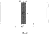
- FIG. 2 is a schematic structural diagram of a supporting plate provided by the embodiment of the present disclosure.
- the supporting plate 4 comprises a bending region 41 and a non-bending region 42 on both sides of the bending region 41, the bending region 41 comprises a dummy bending axis 410, and the supporting plate 4 can be unfolded or folded along the bending axis 410.
- FIG. 3 is a schematic diagram of detail part A in FIG. 2 .
- the bending region 41 is provided with a plurality of openings 43, the opening 43 comprises a dummy first long axis a1 and a dummy first short axis b1, the first long axis a1 of the opening 43 located on the bending axis 410 coincides with the bending axis 410, a direction of the first long axis a1 of the other openings 43 is parallel with a direction of the bending axis 410, and a direction of the first short axis b1 is perpendicular to a direction of the bending axis 410.
- An orthographic projection pattern of the opening 43 on the support plate 4 may be respectively symmetrical about the first long axis a1 and the first short axis b1.
- a distance between inner walls of both sides of the openings 43 in the direction of the first long axis a1 gradually decreases from both ends to middle of the openings (that is, a position of the first short axis b1) along the direction of the first long axis a1, which forms a "dog bone" shape with a greater distance between side walls of both ends of the opening and a narrow middle distance as shown in FIG. 3 .
- the opening 43 is stretched and widened when the supporting plate 4 is bent and tensioned, and a thinner portion in the middle is affected by tensile stress on both sides, so that the supporting plate 4 has excellent extension performance.
- the supporting plate 4 can be stretched and extended simultaneously with length change of the display panel 3, which gives the display panel 3 space for the length change and can disperse and reduce the stress of the supporting plate 4 during folding thereof, thereby accordingly reducing compression stress on the display panel 3, reducing relative misalignment between the supporting plate 4 and the display panel 3, and reducing a risk of the supporting plate 4 from being separated from the display panel 3 and inner film layers of the display panel 3.
- the openings 43 are arranged in an entire bending region 41 according to a certain density array which forms a discontinuous grid structure, and any two adjacent columns of openings 43 are staggered.
- a density of the openings 43 arranged in the bending region 41 can be increased; on the other hand, staggered openings 43 are affected by material strength of an adjacent unopened portion. After bending force disappears, a stretched portion in the middle of the openings 43 can be quickly restored to its original state, so that the supporting plate 4 has a good ability to restore deformation, reduce waviness and creases caused by repeated folding and unfolding of the display panel, and ensure flatness of the display panel 3 after the unfolded state is restored.
- an interval between the openings 43 in one of the two adjacent columns of openings along a direction perpendicular to the bending axis 410 corresponds to the first short axis b1 of the other column of the openings 43. Therefore, the opening 43 is provided with a highest density, and a middle portion of the opening 43 corresponds to a portion with the most unopened material, which gives the openings 43 enough tensile deformation space, and at the same time does not affect a wall thickness of a greater portion of the both ends of the opening 43.
- extension performance and recovery ability of the supporting plate are improved, and an extension rate of the supporting plate 4 can reach more than 10%.
- two adjacent columns of openings 43 may also be arranged in parallel. Therefore, a technical effect of improving extension performance of the supporting plate, and dispersing and reducing stress in the bending region 41 can also be realized, which is not limited herein.
- a shape of the orthographic projection pattern of the two side walls of the opening 43 corresponding to the first long axis a1 on the supporting plate 4 is an arc, and a curvature or radian R of the arc can be calculated according to extension length of the supporting plate 4 in the folded state, deformation amount of the opening 43, and a number of the opening 43.
- the shape of the orthographic projection pattern of the two side walls of the opening 43 corresponding to the first long axis a1 on the supporting plate 4 is not limited to the arc shape. In some embodiments, it can also be any other curve, and no specific restrictions are made here.
- the opening 43 provided by the embodiment of the present disclosure comprises but is not limited to a through-hole or a blind hole. Therefore, the supporting plate 4 can be dispersed and reduce stress during bending.
- FIG. 4 is a schematic diagram of detail part B in FIG. 2 .
- the supporting plate 4 is further provided with a plurality of bending openings 44 arranged at intervals, the bending openings 44 are formed by boundaries on opposite sides of the bending region 41 respectively extending toward the bending region 41 along the direction of the bending axis 410, and an opening direction of the bending opening 44 is equal to or opposite to the direction of the first long axis a1 of the opening 43.
- the bending opening 44 comprises a dummy second long axis a2 and a dummy second short axis b2, the second long axis a2 coincides with the direction of the first long axis a1 of the opening 43 in a same column, and the second short axis b2 is perpendicular to the second long axis a2.
- a distance between inner walls of both sides of the bending openings 44 extending along a direction of the second long axis a2 gradually decreases from both ends to middle of the bending openings 44 (that is, a position of the second short axis) along the direction of the second long axis a2, that is, from an end of the bending openings 44 away from a boundary of the bending region 41 to the second short axis b2, the distance between the inner walls on both sides of the bending openings 44 gradually decreases; from the second short axis b2 to the bending opening 44 located at the opening of a boundary of the bending region 41, the distance between the inner walls on both sides gradually increases, which not only improves extension performance of the supporting plate 4 and reduces squeezing stress on the display panel 3 during the bending process on both sides of the bending region 41, but can reduce an amount of shrinkage caused by deformation of the both sides of the bending region 41 of the supporting plate 4 during the bending process and the depression from the both sides to an inside
- a column of the openings 43 is spaced between adjacent bending openings 44 on a same side of the bending region 41 along the direction perpendicular to the bending axis 410.
- a distance L1 between the opening 43 at both ends in a column of openings adjacent to the bending openings 44 and the boundaries between the both sides of the bending region 41 is greater than a distance L3 between the second short axis b2 and the boundary of the bending region 41, so that the bending opening 44 is provided without openings 43 on both sides of a portion from the second short axis b2 to the opening at boundary, to increase an area of the portion where the opening 43 is not provided around the bending opening 44 on the both sides of the bending region 41, to improve strength of the boundaries on both sides of the bending region 41 of the supporting plate 4, and to improve bending resistance of the supporting plate 4, thereby preventing the boundaries of the both sides of the bending region 41 from breaking due to concentrated stress during the bending process.
- the display panel 3 comprises a panel bending region and a panel non-bending region located at both sides of the panel bending region.
- an orthographic projection region of the bending region 41 of the supporting plate 4 on the display panel 3 covers the panel bending region, and a width of the bending region 41 of the supporting plate 4 in the direction perpendicular to the bending axis 410 is greater than a width of the panel bending region in the direction perpendicular to the bending axis.
- the bending region 41 of the supporting plate 4 beyond the bending region of the panel is stretched and extended during the bending process, which can provide enough space for stress relief and strain dislocation movement at a junction of the panel bending region and the panel non-bending region of the display panel 3, and reduce a risk of film layers of the display panel 3 from being separated.
- the width of any side of the bending region 41 in the direction perpendicular to the bending axis 410 is at least 1 mm greater than the same side of the panel bending region.
- FIG. 5 is a schematic structural diagram of the bending region of the supporting plate provided by the embodiment of the present disclosure.
- a number of the opening 43 in a column of openings adjacent to the bending openings 44 is N
- a distance between the first end of the openings 43 and the boundary of the bending region 41 is L1
- a distance between the first end of the openings 43 and the first end of the adjacent openings in a same column is L2
- FIG. 6 is another schematic structural diagram of the supporting plate provided by the embodiment of the present disclosure.
- the bending region 41 of the supporting plate 4 comprises a first bending region 411 and a second bending region 412 between the first bending region 411 and the non-bending region 42, the bending axis 410 is located in the first bending region 411, the first bending region 411 comprises a first opening 431, the second bending region 412 comprises a second opening 432, and a size and a density of the first opening 431 and a size and a density of the second opening 432 are different.
- FIG. 7 is a schematic diagram of a folded state of a display panel provided by the embodiment of the present disclosure.
- the panel bending region of the display panel 3 further comprise a first panel bending region 31 and a second panel non-bending region 32 between the first panel bending region 31 and the panel non-bending region 33, and the second panel bending region 31 is in a bending transition region of the first panel bending region 31 and the panel non-bending region 33.
- the display panel 3 When the display panel 3 is bent to the folded state, display surfaces of both sides of the panel non-bending region 32 are arranged relatively parallel, the bending region of the panel forms a drop shape, the first panel bending region 31 is concavely bent inward, and the second panel bending region 31 is convexly bent toward the second panel bending region 31 on the opposite side.
- a slope of the second panel bending region 32 is greater than a slope of the first panel bending region 31, which results in the second panel bending region 32 receiving a greater stress than the first panel bending region 31, so that relative misalignment of the second panel bending region 32 is greater than that of the first panel bending region 31, and the risk of film separation is higher than that of the first panel bending region 31.
- the size of the first opening 431 in the first bending region 411 should be greater than the size of the second opening 432 in the second bending 412, and the density of the first opening 431 in the first bending region 411 should be less than the density of the second opening 432 in the second bending region 412.
- the size of the openings and increasing the density of the openings extension performance and ability to recover deformation of the second bending region 412 of the supporting plate are greater than that of the first bending region 411, and the second bending region 412 is dispersed and reduced stress during bending, thereby correspondingly reducing stress received by the second panel bending region 32, so that forces on the display panel 3 are balanced, and the risk of film layers being separated is reduced.
- the size and density of the openings 43 in the bending region 41 are a multi-step change, that is, the size and density of each first opening 431 in the first bending region 411 are equal, and the size and density of each second opening 432 in the second bending region 412 are equal, which can disperse and reduce stress of the second bending region 412 during bending, so that stress in each portion of the display panel 3 is balanced, thereby reducing the risk of film layers from being separated.
- the multi-step change of the size and density of the openings 41 in the bending region 41 is not limited to the three-step change provided by the embodiment of the present disclosure, in other embodiments, it can also comprise fewer or more steps of changes, all of which can realize the above technical effects, which is not limited herein.
- the size and density of the openings 43 in the bending region 41 can also gradually change, that is, along the bending axis 410 to the non-bending region 42, along the bending axis to a boundary between the first bending region 411 and the second bending region 421, or along the boundary between the first bending region 411 and the second bending region to the non-bending region 42, the size of the openings 43 is decreasing (or increasing), the density of the openings 43 is increasing (or decreasing), which can also realize same technical effects as the above embodiments, and is not limited herein.
- the second opening 432 in the second bending region 412 is a through-hole
- the first opening 431 in the first bending region 411 is a blind hole
- an opening of the blind hole is towards a side away from the display panel 3 or close to the display panel 3.
- the opening of the blind hole is towards the side away from the display panel 3, and an unopened portion of the first bending region 411 of the supporting plate 4 remains flat. Therefore, in the case of through-holes combined with blind holes, not only can sufficient extension performance of the supporting plate 4 and recovering deformability be supported, but also a flat portion of the supporting plate 4 can support the first panel bending region 31, which reduces waviness and creases caused by repeated folding and unfolding of the display panel 3, and improves flatness of the display panel 3. Moreover, in some embodiments, the opening of the blind hole may also be towards the side close to the display panel 3, which can also realize the effect of improving extension performance of the supporting plate 4 and restoring the deformability, and is not limited herein.
- the display panel 3 and the supporting plate 4 are bonded by an entire surface of a flexible foldable optical adhesive layer 5.
- the display panel 3 comprises a flip-chip film 35 and a flexible circuit board 36, the flip-chip 35 and the flexible circuit board 36 can be bent to a side of the supporting plate 4 away from the display panel 3. Therefore, a bending of the display panel 3 is not affected, and screen ratio of the foldable display device 100 can also be improved.
- FIG. 10 is a schematic structural diagram of film layers provided by the embodiment of the present disclosure.
- the display panel 3 further comprise a back plate 311, a touch control display device layer 312, a polarizer 313, and a package cover 314 that are laminated, the back plate 311 and the touch control display device layer 312 are bonded by a pressure-sensitive adhesive layer 315, and the package cover 314 and the polarizer 313 are bonded by an optical adhesive layer 316.
- an elastic layer 6 is disposed between the display panel 3 and the supporting plate 4, the elastic layer is disposed between the supporting plate 4 and a foldable optical adhesive layer 5, and covers the supporting plate 4 on an entire surface.
- a material of the elastic layer 6 is silicone resin that is liquid before curing and has good fluidity.
- the silicone resin is screen-printed on a surface of the supporting plate 4, the silicone material can be filled into the opening 43, and after curing, an integrated grid structure can be formed with the opening 43 of the supporting plate.
- the silicone material has good elasticity and elongation properties.
- the elastic layer 6 can follow the adjacent flexible foldable optical adhesive layer 5 to move simultaneously, thereby reducing relative misalignment between the supporting plate 4 and the display panel 3, and reducing a risk of film layers between the display panel 3 and the adjacent film layer from being separated.
- the elastic layer 6 is filled into the opening 43, which can further provide the opening 43 with a good ability to recover from deformation, so that the display panel 3 can be quickly restored to the unfolded state after being folded, thereby effectively eliminating creases and ripples caused by folding.
- the elastic layer 6 can also be replaced by a foam rubber layer, which also has good elongation performance and recovery deformation ability, and can achieve a same technical effect as the elastic layer 6.
- a material of the supporting plate 4 is stainless steel (SUS), which has strong toughness and plasticity, and can not only provide good extension performance for the bending region 41 of the supporting plate 4, but also good strength of the supporting plate itself can further provide good support capacity for each portion of the display panel 3, thereby improving flatness of the display panel 3 when it is unfolded, reducing difficulty of assembling and matching the flexible display panel 3 with the front frame and bottom frame assembly. Moreover, there is no need to replace flexible assembly equipment, reducing investment costs.
- SUS stainless steel
- a thickness of the supporting plate 4 should range from 0.02mm to 1 mm. If the thickness is too thin, supporting strength of the supporting plate 4 is insufficient, and if the thickness is too thick, extension performance and deformation recovery ability of the supporting plate 4 are deteriorated, and a specific value can be selected according to actual needs, which is not limited herein.
- the supporting plate 4 can replace an original back plate 31 in the display panel 3, which is conducive to reducing a thickness of the display panel 3 and reducing stress between the film layers, thereby reducing the relative misalignment between the film layers, reducing the risk of the film layers from being separated, improving the bending resistance of the display panel 3, and also saving the cost of the back plate 31 and reducing corresponding manufacturing process.
- the material of the supporting plate 4 can also be the same or similar material such as Al, Mg, or liquid metal, and can realize the same technical effect as the above-mentioned stainless steel material, which is not limited herein.
- the embodiment of the present disclosure further provides a foldable display device.
- the distance between the inner walls of the both sides of the openings in the direction of the first long axis gradually decreases from the both ends of the openings to the middle along the direction of the first long axis.
- an integrated supporting plate can provide good support for various portions of the display panel to improve flatness of the display device and reduce difficulty in assembling the display panel with the front frame and bottom frame assembly.
Landscapes
- Engineering & Computer Science (AREA)
- Theoretical Computer Science (AREA)
- Computer Hardware Design (AREA)
- Physics & Mathematics (AREA)
- General Physics & Mathematics (AREA)
- Human Computer Interaction (AREA)
- General Engineering & Computer Science (AREA)
- Mathematical Physics (AREA)
- Devices For Indicating Variable Information By Combining Individual Elements (AREA)
Applications Claiming Priority (2)
| Application Number | Priority Date | Filing Date | Title |
|---|---|---|---|
| CN202010427172.2A CN111508370B (zh) | 2020-05-19 | 2020-05-19 | 可折叠显示装置 |
| PCT/CN2020/098016 WO2021232533A1 (fr) | 2020-05-19 | 2020-06-24 | Dispositif d'affichage pliable |
Publications (2)
| Publication Number | Publication Date |
|---|---|
| EP4156152A1 true EP4156152A1 (fr) | 2023-03-29 |
| EP4156152A4 EP4156152A4 (fr) | 2024-06-19 |
Family
ID=71870227
Family Applications (1)
| Application Number | Title | Priority Date | Filing Date |
|---|---|---|---|
| EP20929689.6A Pending EP4156152A4 (fr) | 2020-05-19 | 2020-06-24 | Dispositif d'affichage pliable |
Country Status (6)
| Country | Link |
|---|---|
| US (1) | US12038785B2 (fr) |
| EP (1) | EP4156152A4 (fr) |
| JP (1) | JP2022536882A (fr) |
| KR (1) | KR20210145117A (fr) |
| CN (1) | CN111508370B (fr) |
| WO (1) | WO2021232533A1 (fr) |
Families Citing this family (37)
| Publication number | Priority date | Publication date | Assignee | Title |
|---|---|---|---|---|
| US11885568B2 (en) | 2019-01-09 | 2024-01-30 | Lawrence Livermore National Security, Llc | Systems and methods for periodic nodal surface based reactors, distributors, contactors and heat exchangers |
| CN211928943U (zh) * | 2020-05-29 | 2020-11-13 | 京东方科技集团股份有限公司 | 支撑背板及显示装置 |
| CN111724678A (zh) | 2020-06-08 | 2020-09-29 | 武汉华星光电半导体显示技术有限公司 | 一种柔性显示装置及柔性显示设备 |
| KR102805694B1 (ko) * | 2020-06-24 | 2025-05-14 | 삼성디스플레이 주식회사 | 표시 장치 |
| KR102278840B1 (ko) * | 2020-08-31 | 2021-07-16 | 정민우 | 폴더블 디스플레이 기기를 접는 방법 |
| CN112150921B (zh) | 2020-09-16 | 2022-02-01 | 武汉华星光电半导体显示技术有限公司 | 折叠显示装置 |
| CN112164318B (zh) | 2020-10-14 | 2021-09-03 | 武汉华星光电半导体显示技术有限公司 | 支撑件及可折叠显示模组 |
| CN112289750A (zh) * | 2020-10-28 | 2021-01-29 | 武汉华星光电半导体显示技术有限公司 | 支撑层及柔性显示面板 |
| CN112509466A (zh) * | 2020-11-27 | 2021-03-16 | 武汉华星光电半导体显示技术有限公司 | 可折叠显示面板及可折叠显示装置 |
| US20220183174A1 (en) * | 2020-12-04 | 2022-06-09 | Samsung Electronics Co., Ltd. | Electronic device including flexible display |
| CN112991948A (zh) * | 2021-02-23 | 2021-06-18 | 京东方科技集团股份有限公司 | 一种支撑件以及显示装置 |
| CN215068979U (zh) * | 2021-03-26 | 2021-12-07 | 京东方科技集团股份有限公司 | 柔性支撑层、柔性显示模组以及柔性显示装置 |
| CN112991959B (zh) * | 2021-03-31 | 2023-09-29 | 上海天马微电子有限公司 | 可折叠显示模组及其制作方法、可折叠显示装置 |
| CN113129746A (zh) * | 2021-04-01 | 2021-07-16 | 武汉华星光电技术有限公司 | 支撑复合板及其制备方法、显示模组 |
| US12243448B2 (en) * | 2021-04-23 | 2025-03-04 | E Ink Holdings Inc. | Flexible display device having supporting layer |
| CN113257123A (zh) * | 2021-04-29 | 2021-08-13 | 荣耀终端有限公司 | 一种显示屏模块和电子设备 |
| CN113380145B (zh) * | 2021-06-07 | 2023-04-07 | Oppo广东移动通信有限公司 | 支撑件、柔性屏组件及终端设备 |
| KR20220167819A (ko) | 2021-06-14 | 2022-12-22 | 삼성디스플레이 주식회사 | 표시 장치 및 그것을 포함하는 전자 장치 |
| CN113362718B (zh) * | 2021-06-21 | 2022-07-12 | 武汉华星光电技术有限公司 | 柔性支撑构件、显示模组及移动终端 |
| CN113539102B (zh) * | 2021-07-20 | 2022-09-27 | 武汉华星光电半导体显示技术有限公司 | 支撑组件及柔性显示模组 |
| CN113674626A (zh) * | 2021-08-20 | 2021-11-19 | 京东方科技集团股份有限公司 | 一种显示装置及终端设备 |
| CN113793552B (zh) * | 2021-08-26 | 2023-10-20 | 荣耀终端有限公司 | 一种支撑组件、显示屏和电子设备 |
| CN114093256A (zh) * | 2021-11-02 | 2022-02-25 | 合肥维信诺科技有限公司 | 支撑板和显示面板 |
| CN116129736B (zh) * | 2021-11-15 | 2026-04-03 | 华为技术有限公司 | 电子设备 |
| CN114094027B (zh) * | 2021-11-16 | 2025-06-10 | 京东方科技集团股份有限公司 | 玻璃基板及其制作方法、透明盖板、以及显示装置 |
| KR20230075191A (ko) * | 2021-11-22 | 2023-05-31 | 엘지디스플레이 주식회사 | 폴더블 표시장치 |
| CN114038324A (zh) * | 2021-11-24 | 2022-02-11 | 武汉华星光电半导体显示技术有限公司 | 支撑组件及柔性显示装置 |
| KR20230102744A (ko) * | 2021-12-30 | 2023-07-07 | 주식회사 트리니타스 | 플렉서블 디스플레이 패널 지지용 백플레이트 및 이의 제조방법 |
| CN114360377B (zh) * | 2021-12-31 | 2023-12-22 | 合肥维信诺科技有限公司 | 支撑片及其制备方法、柔性显示面板 |
| CN117292614A (zh) * | 2022-06-20 | 2023-12-26 | 北京小米移动软件有限公司 | 支撑结构、折叠显示屏及终端设备 |
| CN115394188A (zh) * | 2022-07-20 | 2022-11-25 | 合肥维信诺科技有限公司 | 显示面板及电子设备 |
| CN118155510A (zh) * | 2022-08-29 | 2024-06-07 | 武汉华星光电半导体显示技术有限公司 | 显示模组及显示装置 |
| CN115662296A (zh) | 2022-11-01 | 2023-01-31 | 武汉华星光电半导体显示技术有限公司 | 折叠显示模组及折叠显示装置 |
| WO2025004176A1 (fr) * | 2023-06-27 | 2025-01-02 | シャープディスプレイテクノロジー株式会社 | Dispositif d'affichage |
| EP4513297A4 (fr) * | 2023-07-03 | 2026-04-01 | Samsung Electronics Co Ltd | Dispositif électronique pliable comprenant une plaque pouvant supporter un affichage |
| WO2025220852A1 (fr) * | 2024-04-19 | 2025-10-23 | 삼성전자주식회사 | Dispositif électronique comprenant une structure pour protéger le bord d'un écran souple |
| CN119889176A (zh) * | 2025-03-21 | 2025-04-25 | 厦门天马显示科技有限公司 | 支撑组件、显示模组及显示装置 |
Family Cites Families (31)
| Publication number | Priority date | Publication date | Assignee | Title |
|---|---|---|---|---|
| KR102643577B1 (ko) * | 2013-09-13 | 2024-03-04 | 가부시키가이샤 한도오따이 에네루기 켄큐쇼 | 표시 장치 |
| US9983424B2 (en) * | 2015-06-08 | 2018-05-29 | Lg Display Co., Ltd. | Foldable display device |
| KR102506631B1 (ko) | 2015-06-08 | 2023-03-07 | 엘지디스플레이 주식회사 | 폴더블 표시장치 |
| KR102550697B1 (ko) * | 2015-12-30 | 2023-07-04 | 삼성디스플레이 주식회사 | 플렉서블 디스플레이 장치 |
| KR102578589B1 (ko) * | 2016-09-30 | 2023-09-14 | 엘지디스플레이 주식회사 | 플렉서블 표시장치 |
| KR102611993B1 (ko) | 2016-10-12 | 2023-12-08 | 삼성디스플레이 주식회사 | 플렉시블 표시 장치 |
| KR102762585B1 (ko) | 2016-11-30 | 2025-02-05 | 엘지디스플레이 주식회사 | 폴더블 표시 장치 |
| KR102612041B1 (ko) * | 2016-12-30 | 2023-12-07 | 엘지디스플레이 주식회사 | 폴더블 표시 장치 |
| JP2019040120A (ja) * | 2017-08-28 | 2019-03-14 | 株式会社ジャパンディスプレイ | 液晶表示装置 |
| US10694625B2 (en) * | 2017-10-31 | 2020-06-23 | Lg Display Co., Ltd. | Rollable display |
| KR102398331B1 (ko) * | 2017-11-01 | 2022-05-16 | 엘지전자 주식회사 | 플렉서블 디스플레이 유닛 및 이를 구비하는 이동 단말기 |
| KR102456889B1 (ko) * | 2017-11-01 | 2022-10-21 | 엘지전자 주식회사 | 플렉서블 프레임 및 이를 구비하는 플렉서블 디스플레이 유닛 |
| CN113053250B (zh) * | 2017-12-28 | 2022-10-04 | 乐金显示有限公司 | 可折叠显示器 |
| CN108417152B (zh) * | 2018-04-16 | 2020-08-14 | 京东方科技集团股份有限公司 | 可折叠的柔性屏幕终端 |
| CN108766991B (zh) * | 2018-06-05 | 2020-10-13 | 武汉华星光电半导体显示技术有限公司 | 显示面板及电子设备 |
| CN109032251A (zh) * | 2018-06-28 | 2018-12-18 | 武汉华星光电半导体显示技术有限公司 | 一种柔性显示模组及其承载中框 |
| KR101945985B1 (ko) * | 2018-06-28 | 2019-02-08 | 엘지디스플레이 주식회사 | 표시 장치 |
| KR20200052621A (ko) * | 2018-11-07 | 2020-05-15 | 엘지디스플레이 주식회사 | 폴더블 디스플레이 장치 |
| CN109628908B (zh) * | 2018-11-26 | 2020-02-18 | 武汉华星光电半导体显示技术有限公司 | 一种用于柔性oled面板薄膜封装的掩模版 |
| US20200168846A1 (en) | 2018-11-26 | 2020-05-28 | Wuhan China Star Optoelectronics Semiconductor Display Technology Co., Ltd. | A mask used for thin-film encapsulation of a flexible oled panel |
| US10642313B1 (en) * | 2018-12-13 | 2020-05-05 | Innolux Corporation | Foldable display device and operation method of electronic device |
| CN109638056B (zh) * | 2018-12-19 | 2021-12-28 | 武汉华星光电半导体显示技术有限公司 | 一种柔性显示面板及其制作方法 |
| CN109887928B (zh) | 2019-01-24 | 2021-05-07 | 武汉华星光电半导体显示技术有限公司 | 一种柔性显示面板 |
| CN109817680B (zh) * | 2019-01-31 | 2021-03-16 | 武汉华星光电半导体显示技术有限公司 | 柔性基板以及显示面板 |
| EP3737074B1 (fr) * | 2019-03-11 | 2022-05-04 | Samsung Electronics Co., Ltd. | Appareil électronique comprenant une plaque conductrice pliable |
| BR112021023955B1 (pt) * | 2019-05-31 | 2024-03-05 | Samsung Electronics Co., Ltd | Dispositivo eletrônico dobrável incluindo estrutura de proteção de exibidor |
| CN110335544B (zh) | 2019-06-18 | 2020-12-25 | 武汉华星光电半导体显示技术有限公司 | Oled显示面板及显示装置 |
| CN110649087B (zh) * | 2019-10-31 | 2022-06-10 | 京东方科技集团股份有限公司 | 背膜及柔性显示面板 |
| CN110767096B (zh) * | 2019-11-15 | 2021-12-03 | 京东方科技集团股份有限公司 | 支撑结构及显示装置 |
| CN110992828B (zh) * | 2019-11-28 | 2022-12-20 | 京东方科技集团股份有限公司 | 用于柔性显示装置的支撑基板和柔性显示装置 |
| CN110853525B (zh) * | 2019-12-10 | 2022-03-01 | Oppo广东移动通信有限公司 | 折叠屏组件及电子设备 |
-
2020
- 2020-05-19 CN CN202010427172.2A patent/CN111508370B/zh active Active
- 2020-06-24 KR KR1020217006158A patent/KR20210145117A/ko not_active Ceased
- 2020-06-24 EP EP20929689.6A patent/EP4156152A4/fr active Pending
- 2020-06-24 US US17/049,571 patent/US12038785B2/en active Active
- 2020-06-24 JP JP2021514576A patent/JP2022536882A/ja active Pending
- 2020-06-24 WO PCT/CN2020/098016 patent/WO2021232533A1/fr not_active Ceased
Also Published As
| Publication number | Publication date |
|---|---|
| US20230114378A1 (en) | 2023-04-13 |
| CN111508370A (zh) | 2020-08-07 |
| KR20210145117A (ko) | 2021-12-01 |
| EP4156152A4 (fr) | 2024-06-19 |
| CN111508370B (zh) | 2023-01-24 |
| US12038785B2 (en) | 2024-07-16 |
| JP2022536882A (ja) | 2022-08-22 |
| WO2021232533A1 (fr) | 2021-11-25 |
Similar Documents
| Publication | Publication Date | Title |
|---|---|---|
| US12038785B2 (en) | Foldable display device | |
| US11979995B2 (en) | Foldable display device | |
| US10310566B2 (en) | Foldable mechanism of mobile terminal and mobile terminal | |
| CN214476074U (zh) | 柔性显示模组 | |
| US20230154360A1 (en) | Display panel and flexible display device | |
| CN110096176B (zh) | 一种触控显示装置及其制作方法、终端设备 | |
| CN114170912B (zh) | 显示模组及电子设备 | |
| CN113129752A (zh) | 支撑板及折叠显示屏 | |
| CN110792905A (zh) | 支撑结构及显示装置 | |
| CN109785750B (zh) | 显示面板、柔性线路板及显示装置 | |
| CN111292622A (zh) | 显示面板及显示装置 | |
| CN108962117B (zh) | 一种可折叠的显示面板及可折叠显示装置 | |
| CN114038345A (zh) | 显示模组和显示装置 | |
| CN110636688B (zh) | 柔性显示装置 | |
| CN111554202B (zh) | 一种显示面板和显示装置 | |
| US20260013056A1 (en) | Display panel and display device including the same | |
| WO2023221060A1 (fr) | Écran pliable et dispositif terminal | |
| CN210181359U (zh) | 显示面板 | |
| US11563036B2 (en) | Array substrate and fabrication method thereof, display panel and display module | |
| CN111724683B (zh) | 显示面板及显示装置 | |
| US6816212B2 (en) | Assembling structure of a metal frame and an electric module for use in a liquid crystal display | |
| CN114783291B (zh) | 显示基板、柔性线路板和显示装置 | |
| US20200057325A1 (en) | Liquid crystal display panel | |
| CN110299074A (zh) | 显示面板及显示装置 | |
| JP2004054050A (ja) | タッチパネルおよびこのタッチパネルを備えた携帯情報端末 |
Legal Events
| Date | Code | Title | Description |
|---|---|---|---|
| STAA | Information on the status of an ep patent application or granted ep patent |
Free format text: STATUS: UNKNOWN |
|
| STAA | Information on the status of an ep patent application or granted ep patent |
Free format text: STATUS: THE INTERNATIONAL PUBLICATION HAS BEEN MADE |
|
| PUAI | Public reference made under article 153(3) epc to a published international application that has entered the european phase |
Free format text: ORIGINAL CODE: 0009012 |
|
| STAA | Information on the status of an ep patent application or granted ep patent |
Free format text: STATUS: REQUEST FOR EXAMINATION WAS MADE |
|
| 17P | Request for examination filed |
Effective date: 20211015 |
|
| AK | Designated contracting states |
Kind code of ref document: A1 Designated state(s): AL AT BE BG CH CY CZ DE DK EE ES FI FR GB GR HR HU IE IS IT LI LT LU LV MC MK MT NL NO PL PT RO RS SE SI SK SM TR |
|
| DAV | Request for validation of the european patent (deleted) | ||
| DAX | Request for extension of the european patent (deleted) | ||
| A4 | Supplementary search report drawn up and despatched |
Effective date: 20240523 |
|
| RIC1 | Information provided on ipc code assigned before grant |
Ipc: G06F 1/16 20060101ALI20240516BHEP Ipc: G09F 9/30 20060101AFI20240516BHEP |