EP4156439A1 - Procédé de coordination de puissance pour centrale photovoltaïque, et centrale électrique - Google Patents
Procédé de coordination de puissance pour centrale photovoltaïque, et centrale électrique Download PDFInfo
- Publication number
- EP4156439A1 EP4156439A1 EP20942219.5A EP20942219A EP4156439A1 EP 4156439 A1 EP4156439 A1 EP 4156439A1 EP 20942219 A EP20942219 A EP 20942219A EP 4156439 A1 EP4156439 A1 EP 4156439A1
- Authority
- EP
- European Patent Office
- Prior art keywords
- arrays
- power
- active
- available
- reactive
- Prior art date
- Legal status (The legal status is an assumption and is not a legal conclusion. Google has not performed a legal analysis and makes no representation as to the accuracy of the status listed.)
- Granted
Links
Images




Classifications
-
- H—ELECTRICITY
- H02—GENERATION; CONVERSION OR DISTRIBUTION OF ELECTRIC POWER
- H02J—ELECTRIC POWER NETWORKS; CIRCUIT ARRANGEMENTS OR SYSTEMS FOR SUPPLYING OR DISTRIBUTING ELECTRIC POWER; SYSTEMS FOR STORING ELECTRIC ENERGY
- H02J3/00—Circuit arrangements for AC mains or AC distribution networks
- H02J3/38—Arrangements for feeding a single network from two or more generators or sources in parallel; Arrangements for feeding already energised networks from additional generators or sources in parallel
- H02J3/46—Controlling the sharing of generated power between the generators, sources or networks
- H02J3/466—Scheduling or selectively controlling the operation of the generators or sources, e.g. connecting or disconnecting generators to meet a demand
-
- H—ELECTRICITY
- H02—GENERATION; CONVERSION OR DISTRIBUTION OF ELECTRIC POWER
- H02J—ELECTRIC POWER NETWORKS; CIRCUIT ARRANGEMENTS OR SYSTEMS FOR SUPPLYING OR DISTRIBUTING ELECTRIC POWER; SYSTEMS FOR STORING ELECTRIC ENERGY
- H02J3/00—Circuit arrangements for AC mains or AC distribution networks
- H02J3/38—Arrangements for feeding a single network from two or more generators or sources in parallel; Arrangements for feeding already energised networks from additional generators or sources in parallel
- H02J3/381—Dispersed generators
-
- H—ELECTRICITY
- H02—GENERATION; CONVERSION OR DISTRIBUTION OF ELECTRIC POWER
- H02J—ELECTRIC POWER NETWORKS; CIRCUIT ARRANGEMENTS OR SYSTEMS FOR SUPPLYING OR DISTRIBUTING ELECTRIC POWER; SYSTEMS FOR STORING ELECTRIC ENERGY
- H02J3/00—Circuit arrangements for AC mains or AC distribution networks
- H02J3/38—Arrangements for feeding a single network from two or more generators or sources in parallel; Arrangements for feeding already energised networks from additional generators or sources in parallel
- H02J3/46—Controlling the sharing of generated power between the generators, sources or networks
- H02J3/48—Controlling the sharing of active power
-
- H—ELECTRICITY
- H02—GENERATION; CONVERSION OR DISTRIBUTION OF ELECTRIC POWER
- H02J—ELECTRIC POWER NETWORKS; CIRCUIT ARRANGEMENTS OR SYSTEMS FOR SUPPLYING OR DISTRIBUTING ELECTRIC POWER; SYSTEMS FOR STORING ELECTRIC ENERGY
- H02J3/00—Circuit arrangements for AC mains or AC distribution networks
- H02J3/38—Arrangements for feeding a single network from two or more generators or sources in parallel; Arrangements for feeding already energised networks from additional generators or sources in parallel
- H02J3/46—Controlling the sharing of generated power between the generators, sources or networks
- H02J3/50—Controlling the sharing of reactive power
-
- H—ELECTRICITY
- H02—GENERATION; CONVERSION OR DISTRIBUTION OF ELECTRIC POWER
- H02J—ELECTRIC POWER NETWORKS; CIRCUIT ARRANGEMENTS OR SYSTEMS FOR SUPPLYING OR DISTRIBUTING ELECTRIC POWER; SYSTEMS FOR STORING ELECTRIC ENERGY
- H02J2101/00—Supply or distribution of decentralised, dispersed or local electric power generation
- H02J2101/20—Dispersed power generation using renewable energy sources
- H02J2101/22—Solar energy
- H02J2101/24—Photovoltaics
- H02J2101/25—Photovoltaics involving maximum power point tracking control for photovoltaic sources
-
- H—ELECTRICITY
- H02—GENERATION; CONVERSION OR DISTRIBUTION OF ELECTRIC POWER
- H02J—ELECTRIC POWER NETWORKS; CIRCUIT ARRANGEMENTS OR SYSTEMS FOR SUPPLYING OR DISTRIBUTING ELECTRIC POWER; SYSTEMS FOR STORING ELECTRIC ENERGY
- H02J3/00—Circuit arrangements for AC mains or AC distribution networks
- H02J3/001—Arrangements for handling faults or abnormalities, e.g. emergencies or contingencies
- H02J3/0014—Arrangements for handling faults or abnormalities, e.g. emergencies or contingencies for preventing or reducing power oscillations in networks
- H02J3/00142—Oscillations concerning frequency
-
- H—ELECTRICITY
- H02—GENERATION; CONVERSION OR DISTRIBUTION OF ELECTRIC POWER
- H02J—ELECTRIC POWER NETWORKS; CIRCUIT ARRANGEMENTS OR SYSTEMS FOR SUPPLYING OR DISTRIBUTING ELECTRIC POWER; SYSTEMS FOR STORING ELECTRIC ENERGY
- H02J3/00—Circuit arrangements for AC mains or AC distribution networks
- H02J3/12—Arrangements for adjusting voltage in AC networks by changing a characteristic of the network load
- H02J3/16—Arrangements for adjusting voltage in AC networks by changing a characteristic of the network load by adjustment of reactive power
-
- H—ELECTRICITY
- H02—GENERATION; CONVERSION OR DISTRIBUTION OF ELECTRIC POWER
- H02J—ELECTRIC POWER NETWORKS; CIRCUIT ARRANGEMENTS OR SYSTEMS FOR SUPPLYING OR DISTRIBUTING ELECTRIC POWER; SYSTEMS FOR STORING ELECTRIC ENERGY
- H02J3/00—Circuit arrangements for AC mains or AC distribution networks
- H02J3/28—Arrangements for balancing of the load in networks by storage of energy
- H02J3/32—Arrangements for balancing of the load in networks by storage of energy using batteries or super capacitors with converting means
-
- Y—GENERAL TAGGING OF NEW TECHNOLOGICAL DEVELOPMENTS; GENERAL TAGGING OF CROSS-SECTIONAL TECHNOLOGIES SPANNING OVER SEVERAL SECTIONS OF THE IPC; TECHNICAL SUBJECTS COVERED BY FORMER USPC CROSS-REFERENCE ART COLLECTIONS [XRACs] AND DIGESTS
- Y02—TECHNOLOGIES OR APPLICATIONS FOR MITIGATION OR ADAPTATION AGAINST CLIMATE CHANGE
- Y02E—REDUCTION OF GREENHOUSE GAS [GHG] EMISSIONS, RELATED TO ENERGY GENERATION, TRANSMISSION OR DISTRIBUTION
- Y02E10/00—Energy generation through renewable energy sources
- Y02E10/50—Photovoltaic [PV] energy
- Y02E10/56—Power conversion systems, e.g. maximum power point trackers
-
- Y—GENERAL TAGGING OF NEW TECHNOLOGICAL DEVELOPMENTS; GENERAL TAGGING OF CROSS-SECTIONAL TECHNOLOGIES SPANNING OVER SEVERAL SECTIONS OF THE IPC; TECHNICAL SUBJECTS COVERED BY FORMER USPC CROSS-REFERENCE ART COLLECTIONS [XRACs] AND DIGESTS
- Y02—TECHNOLOGIES OR APPLICATIONS FOR MITIGATION OR ADAPTATION AGAINST CLIMATE CHANGE
- Y02E—REDUCTION OF GREENHOUSE GAS [GHG] EMISSIONS, RELATED TO ENERGY GENERATION, TRANSMISSION OR DISTRIBUTION
- Y02E40/00—Technologies for an efficient electrical power generation, transmission or distribution
- Y02E40/30—Reactive power compensation
Definitions
- This application relates to the field of power electronic technologies, and in particular, to a power coordination method for a photovoltaic station and a station.
- the photovoltaic station is usually connected to a grid to transmit solar photovoltaic power to the grid.
- the photovoltaic station usually includes a plurality of solar cell arrays, arrays for short in the following. Each array includes a plurality of inverters.
- the inverter converts a direct current of a solar panel into an alternating current.
- the photovoltaic station can adjust power of the arrays (the power includes reactive power and active power).
- the power includes reactive power and active power.
- one or more arrays in the photovoltaic station are usually set to sample arrays.
- the sample array works in a natural maximum power generation mode, that is, the sample array does not participate in power adjustment of the photovoltaic station.
- An available power capacity of the sample array is obtained by using available power of all inverters in the sample array.
- the available power capacity of the photovoltaic station can be obtained based on the available power capacity of the sample array.
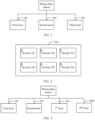
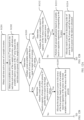
- FIG. 1 is a schematic diagram of a photovoltaic station.
- the photovoltaic station includes three arrays, namely, a first array 100, a second array 200, and a third array 300, is used for description.
- the second array 200 is a sample array. Descriptions are provided by using an example in which the second array 200 includes six inverters (an inverter 201 to an inverter 206). Actually, more inverters may be included. Specifically, referring to FIG. 2 , an available power capacity of the second array 200 is obtained by using available power of the six inverters. Because the photovoltaic station has three arrays, an available power capacity of the photovoltaic station can be obtained only by multiplying the available power capacity of the second array 200 by 3.
- This application provides a power coordination method for a photovoltaic station and a station, to improve accuracy of active power adjustment and reactive power adjustment.
- an embodiment of this application provides a power coordination method for a photovoltaic station.
- the photovoltaic station includes M arrays. N arrays in the M arrays require power coordination.
- the array requiring power adjustment includes n normally-running inverters. For example, for any array, s inverters are selected from normal-running inverters as sample inverters. Real-time active power of the s sample inverters are obtained. Then, an available active capacity of the array is obtained based on the real-time active power of the s sample inverters, and an available reactive capacity of the array is obtained based on the real-time active power of the s sample inverters. By analogy, available active capacities and available reactive capacities of all the arrays requiring power adjustment are obtained.
- active power of the photovoltaic station is allocated to the N arrays based on the available active capacities respectively corresponding to the N arrays
- reactive power of the photovoltaic station is allocated to the N arrays based on the available reactive capacities respectively corresponding to the N arrays.
- an available power capacity of the photovoltaic station is not obtained based on available active capacities of all inverters in only one sample array any more. Instead, sample inverters are disposed in all the arrays requiring power adjustment, that is, sample inverters are distributed in each array requiring power adjustment, and the sample inverters are not concentrated in one array any more. Because the sample inverters come from the arrays requiring power adjustment, differences between inverters and differences between the arrays can be fully exploited, and the available active capacities of the arrays can be more accurately obtained by using the sample inverters. Therefore, a more accurate available power capacity of the photovoltaic station is obtained by using relatively accurate available active capacities.
- real-time active power of any array may be obtained by using average active power.
- average active power of a j th array is obtained based on real-time active power of s sample inverters; and an available active capacity of the j th array is obtained based on the average active power of the j th array and n.
- real-time reactive power of the any array may be obtained by using the real-time active power.
- an available reactive capacity of the j th array is obtained based on the real-time active power of the s sample inverters, maximum apparent power of the sample inverter, and n.
- the photovoltaic station obtains the available active capacities and the available reactive capacities of the arrays by using the sample inverters, and allocates available active capacities and available reactive capacities to the corresponding arrays based on target active power and target reactive power of the station and priorities of the arrays, to differentially coordinate available power capacities of the arrays.
- the active power is allocated to the arrays. Specifically, the active power is allocated to the N arrays based on the target active power of the station, the priorities of the N arrays, and the available active capacities respectively corresponding to the N arrays.
- the reactive power may be further allocated to the arrays.
- the reactive power is allocated to the N arrays based on the target reactive power of the station, the priorities of the N arrays, and the available reactive capacities respectively corresponding to the N arrays.
- the available reactive capacities are first adjusted, and then the available active capacities are adjusted, so that when the available reactive capacities of the arrays are less than the target reactive power of the station, available active capacities of some arrays can be scarified to enable the available reactive capacities to reach the target reactive power of the station, thereby reducing energy consumption, improving grid voltage quality, reducing a penalty, and increasing a revenue.
- the N arrays include at least the following arrays of two priorities: arrays of a first priority and arrays of a second priority, where the first priority is higher than the second priority; and when a total available reactive capacity of the N arrays is greater than or equal to the target reactive power, and a total available reactive capacity of the arrays of the first priority is greater than or equal to the target reactive power, the target reactive power is allocated to the arrays of the first priority based on ratios of available reactive capacities of the arrays to the total available reactive capacity of the arrays of the first priority.
- the N arrays include at least the following arrays of two priorities: arrays of a first priority and arrays of a second priority, where the first priority is higher than the second priority; and when a total available reactive capacity of the N arrays is greater than or equal to the target reactive power, and a total available reactive capacity of the arrays of the first priority is less than the target reactive power, full-amount allocation is performed on the arrays of the first priority based on available reactive capacities of the arrays, and reactive power that is of the target reactive power and that remains after allocation is performed on the first priority is allocated to the arrays of the second priority based on ratios of available reactive capacities of the arrays to a total available reactive capacity of the arrays of the second priority.
- active power of the arrays may change. Therefore, active power may be newly allocated to the arrays.
- the target active power is allocated to the arrays of the first priority based on ratios of available active capacities of the arrays to the total available active capacity of the arrays of the first priority.
- another manner of newly allocating the active power is as follows: When a total available active capacity of the N arrays is greater than or equal to the target active power, and a total available active capacity of the arrays of the first priority is less than the target active power, full-amount allocation is performed on the arrays of the first priority based on available active capacities of the arrays, and active power that is of the target active power and that remains after allocation is performed on the first priority is allocated to the arrays of the second priority based on ratios of available active capacities of the arrays to a total available active capacity of the arrays of the second priority.
- still another manner of newly allocating the active power is as follows: When a total available active capacity of the N arrays is less than the target active power, full-amount allocation is performed based on the available active capacities respectively corresponding to the N arrays.
- Still another manner of allocating the reactive power to the arrays is as follows: When a total available reactive capacity of the N arrays is less than the target reactive power, full-amount allocation is first performed based on the available reactive capacities respectively corresponding to the N arrays, and then reactive power is allocated in descending order of power factors of the N arrays, until all the target reactive power is allocated.
- active power of the arrays may change. Therefore, active power may be newly allocated to the arrays.
- an updated available active capacity of the j th array is obtained based on allocated reactive power of the j th array in the N arrays and maximum apparent power of the j th array;
- the N arrays include at least the following arrays of two priorities: arrays of a first priority and arrays of a second priority, where the first priority is higher than the second priority; and when an updated total available active capacity of the N arrays is greater than or equal to the target active power, and an updated total available active capacity of the arrays of the first priority is greater than or equal to the target active power, the target active power is allocated to the arrays of the first priority based on ratios of updated available active capacities of the arrays to the updated total available active capacity of the arrays of the first priority.
- an updated available active capacity of the j th array is obtained based on allocated reactive power of the j th array in the N arrays and maximum apparent power of the j th array;
- the N arrays include at least the following arrays of two priorities: arrays of a first priority and arrays of a second priority, where the first priority is higher than the second priority; and when an updated total available active capacity of the N arrays is greater than or equal to the target active power, and an updated total available active capacity of the arrays of the first priority is less than the target active power, full-amount allocation is performed on the arrays of the first priority based on updated available active capacities of the arrays, and active power that is of the target active power and that remains after allocation is performed on the first priority is allocated to the arrays of the second priority based on ratios of updated available active capacities of the arrays to an updated total available active capacity of the arrays of the second priority.
- Still another manner of newly allocating the active power is as follows: An updated available active capacity of the j th array is obtained based on allocated reactive power of the j th array in the N arrays and maximum apparent power of the j th array; the N arrays include at least the following arrays of two priorities: arrays of a first priority and arrays of a second priority, where the first priority is higher than the second priority; and when an updated total available active capacity of the N arrays is less than the target active power, full-amount allocation is performed based on updated available active capacities respectively corresponding to the N arrays.
- the active power may be first allocated to the arrays, and then the reactive power may be allocated to the arrays.
- a manner of first allocating the active power to the arrays is as follows: When a total available active capacity of the N arrays is greater than or equal to target active power, the target active power is allocated to the N arrays based on ratios of the available active capacities of the arrays to the total available active capacity of the N arrays; or when a total available active capacity of the N arrays is less than the target active power, full-amount allocation is performed based on the available active capacities respectively corresponding to the N arrays.
- the reactive power may be allocated to the arrays.
- the target reactive power is allocated to the N arrays based on ratios of the available reactive capacities of the arrays to the total available reactive capacity of the N arrays; or when a total available reactive capacity of the N arrays is less than the target reactive power, full-amount allocation is performed based on the available reactive capacities respectively corresponding to the N arrays.
- the reactive power may be first allocated to the arrays.
- the reactive power may be first allocated to the arrays.
- full-amount allocation is first performed based on the available reactive capacities respectively corresponding to the N arrays, and then reactive power is allocated in descending order of power factors of the N arrays, until all the target reactive power is allocated, where allocated reactive power of each of the N arrays is less than or equal to maximum apparent power of the array; or when a total available reactive capacity of the N arrays is greater than or equal to the target reactive power, the target active power is allocated to the N arrays based on ratios of the available reactive capacities of the arrays to the total available reactive capacity of the N arrays.
- inverter power allocation is dynamically adjusted, to increase an electric energy yield, fully utilize the available active capacities and the available reactive capacities of the arrays, and maximize a power range.
- inverter power allocation is dynamically adjusted, to increase an electric energy yield, fully utilize the available active capacities and the available reactive capacities of the arrays, and maximize a power range.
- an embodiment of this application provides a photovoltaic station. All the foregoing power coordination methods for the photovoltaic station can be applied to the photovoltaic station provided in this embodiment of this application.
- the station controller allocates active power to the N arrays based on available active capacities respectively corresponding to the N arrays, where an available active capacity of the j th array in the N arrays is obtained based on real-time active power of the s sample inverters; and allocates reactive power to the N arrays based on available reactive capacities respectively corresponding to the N arrays, where an available reactive capacity of the j th array in the N arrays is obtained based on the real-time active power of the s sample inverters.
- Sample inverters are deployed in each array requiring power coordination, and sample inverters are not concentrated in one sample array any more, but distributed in the arrays requiring power coordination in the photovoltaic station.
- the sample inverters are more evenly and widely distributed, and obtained available active capacities are more accurate, that is, the sample inverter is more representative than the sample array. Because the sample inverters come from the arrays requiring power adjustment, differences between inverters and differences between the arrays can be fully exploited, and the available active capacities of the arrays can be more accurately obtained by using the sample inverters. Therefore, a more accurate available power capacity of the photovoltaic station is obtained by using relatively accurate available active capacities.
- the photovoltaic station includes not only the station controller, but also an array controller.
- the station controller obtains available power capacities of the arrays by using the array controller, and allocates the active power and the reactive power to the corresponding arrays based on target active power and target reactive power of the station and priorities of the arrays, to differentially coordinate power of the arrays.
- the array controller obtains average active power of the j th array based on the real-time active power of the s sample inverters; and obtains the available active capacity of the j th array based on the average active power of the j th array and n.
- the array controller obtains the available reactive capacity of the j th array based on the real-time active power of the s sample inverters, maximum apparent power of the sample inverter, and n.
- the photovoltaic station obtains the available active capacities and the available reactive capacities of the arrays by using the sample inverters, and allocates available active capacities and available reactive capacities to the corresponding arrays based on the target active power and the target reactive power of the station and the priorities of the arrays, to differentially coordinate the available power capacities of the arrays.
- the station controller first allocates the active power to the arrays. Specifically, the station controller allocates the active power to the N arrays based on the target active power of the station, the priorities of the N arrays, and the available active capacities respectively corresponding to the N arrays.
- the station controller may further allocate the reactive power to the arrays.
- the station controller allocates the reactive power to the N arrays based on the target reactive power of the station, the priorities of the N arrays, and the available reactive capacities respectively corresponding to the N arrays.
- the station controller first adjusts the available reactive capacities, and then adjusts the available active capacities, so that when the available reactive capacities of the arrays are less than the target reactive power of the station, available active capacities of some arrays can be scarified to enable the available reactive capacities to reach the target reactive power of the station, thereby reducing energy consumption, improving grid voltage quality, reducing a penalty, and increasing a revenue.
- the N arrays include at least the following arrays of two priorities: arrays of a first priority and arrays of a second priority, where the first priority is higher than the second priority; and when a total available reactive capacity of the N arrays is greater than or equal to the target reactive power, and a total available reactive capacity of the arrays of the first priority is greater than or equal to the target reactive power, the station controller allocates the target reactive power to the arrays of the first priority based on ratios of available reactive capacities of the arrays to the total available reactive capacity of the arrays of the first priority.
- the N arrays include at least the following arrays of two priorities: arrays of a first priority and arrays of a second priority, where the first priority is higher than the second priority; and when a total available reactive capacity of the N arrays is greater than or equal to the target reactive power, and a total available reactive capacity of the arrays of the first priority is less than the target reactive power, full-amount allocation is performed on the arrays of the first priority based on available reactive capacities of the arrays, and reactive power that is of the target reactive power and that remains after allocation is performed on the first priority is allocated to the arrays of the second priority based on ratios of available reactive capacities of the arrays to a total available reactive capacity of the arrays of the second priority.
- active power of the arrays may change. Therefore, the station controller may newly allocate active power to the arrays.
- the target active power is allocated to the arrays of the first priority based on ratios of available active capacities of the arrays to the total available active capacity of the arrays of the first priority.
- another manner in which the station controller newly allocates the active power to the arrays is as follows: When a total available active capacity of the N arrays is greater than or equal to the target active power, and a total available active capacity of the arrays of the first priority is less than the target active power, full-amount allocation is performed on the arrays of the first priority based on available active capacities of the arrays, and active power that is of the target active power and that remains after allocation is performed on the first priority is allocated to the arrays of the second priority based on ratios of available active capacities of the arrays to a total available active capacity of the arrays of the second priority.
- Still another manner in which the station controller newly allocates the active power to the arrays is as follows: When a total available active capacity of the N arrays is less than the target active power, full-amount allocation is performed based on the available active capacities respectively corresponding to the N arrays.
- Still another manner in which the station controller allocates the reactive power to the arrays is as follows: When a total available reactive capacity of the N arrays is less than the target reactive power, full-amount allocation is first performed based on the available reactive capacities respectively corresponding to the N arrays, and then reactive power is allocated in descending order of power factors of the N arrays, until all the target reactive power is allocated.
- active power of the arrays may change. Therefore, active power may be newly allocated to the arrays.
- an updated available active capacity of the j th array is obtained based on allocated reactive power of the j th array in the N arrays and maximum apparent power of the j th array;
- the N arrays include at least the following arrays of two priorities: arrays of a first priority and arrays of a second priority, where the first priority is higher than the second priority; and when an updated total available active capacity of the N arrays is greater than or equal to the target active power, and an updated total available active capacity of the arrays of the first priority is greater than or equal to the target active power, the target active power is allocated to the arrays of the first priority based on ratios of updated available active capacities of the arrays to the updated total available active capacity of the arrays of the first priority.
- an updated available active capacity of the j th array is obtained based on allocated reactive power of the j th array in the N arrays and maximum apparent power of the j th array;
- the N arrays include at least the following arrays of two priorities: arrays of a first priority and arrays of a second priority, where the first priority is higher than the second priority; and when an updated total available active capacity of the N arrays is greater than or equal to the target active power, and an updated total available active capacity of the arrays of the first priority is less than the target active power, full-amount allocation is performed on the arrays of the first priority based on updated available active capacities of the arrays, and active power that is of the target active power and that remains after allocation is performed on the first priority is allocated to the arrays of the second priority based on ratios of updated available active capacities of the arrays to an updated total available active capacity of the arrays of the second priority.
- Still another manner in which the station controller newly allocates the active power to the arrays is as follows: An updated available active capacity of the j th array is obtained based on allocated reactive power of the j th array in the N arrays and maximum apparent power of the j th array; the N arrays include at least the following arrays of two priorities: arrays of a first priority and arrays of a second priority, where the first priority is higher than the second priority; and when an updated total available active capacity of the N arrays is less than the target active power, full-amount allocation is performed based on updated available active capacities respectively corresponding to the N arrays.
- the active power may be first allocated to the arrays, and then the reactive power may be allocated to the arrays.
- a manner in which the station controller first allocates the active power to the arrays is as follows: When a total available active capacity of the N arrays is greater than or equal to target active power, the target active power is allocated to the N arrays based on ratios of the available active capacities of the arrays to the total available active capacity of the N arrays; or when a total available active capacity of the N arrays is less than the target active power, full-amount allocation is performed based on the available active capacities respectively corresponding to the N arrays.
- the station controller may allocate the reactive power to the arrays.
- the target reactive power is allocated to the N arrays based on ratios of the available reactive capacities of the arrays to the total available reactive capacity of the N arrays; or when a total available reactive capacity of the N arrays is less than the target reactive power, full-amount allocation is performed based on the available reactive capacities respectively corresponding to the N arrays.
- the station controller may first allocate the reactive power to the arrays.
- the station controller may first allocate the reactive power to the arrays.
- the reactive power is allocated in a manner, when a total available reactive capacity of the N arrays is less than target reactive power, full-amount allocation is first performed based on the available reactive capacities respectively corresponding to the N arrays, and then reactive power is allocated in descending order of power factors of the N arrays, until all the target reactive power is allocated, where allocated reactive power of each of the N arrays is less than or equal to maximum apparent power of the array; or when a total available reactive capacity of the N arrays is greater than or equal to the target reactive power, the target active power is allocated to the N arrays based on ratios of the available reactive capacities of the arrays to the total available reactive capacity of the N arrays.
- the array controller dynamically adjusts inverter power allocation, to increase an electric energy yield, fully utilize the available active capacities and the available reactive capacities of the arrays, and maximize a power range.
- the array controller dynamically adjusts inverter power allocation, to increase an electric energy yield, fully utilize the available active capacities and the available reactive capacities of the arrays, and maximize a power range.
- the active power of the photovoltaic station is allocated to the N arrays based on the available active capacities respectively corresponding to the N arrays
- the reactive power of the photovoltaic station is allocated to the N arrays based on the available reactive capacities respectively corresponding to the N arrays.
- an available power capacity of the photovoltaic station is not obtained based on available active capacities of all inverters in only one sample array any more. Instead, sample inverters are disposed in all the arrays requiring power adjustment, that is, sample inverters are distributed in each array requiring power adjustment, and the sample inverters are not concentrated in one array any more. Because the sample inverters come from the arrays requiring power adjustment, differences between inverters and differences between the arrays can be fully exploited, and the available active capacities of the arrays can be more accurately obtained by using the sample inverters. Therefore, a more accurate available power capacity of the photovoltaic station is obtained by using relatively accurate available active capacities.
- sample inverters are disposed in arrays, that is, available power capacities of the arrays are obtained based on real-time active power of the sample inverters.
- FIG. 3 is a schematic diagram of a photovoltaic station according to an embodiment of this application.
- the photovoltaic station provided in this application includes M arrays: a first array 100, a second array 200, ..., and a M th array M00.
- the M arrays have N arrays requiring power coordination.
- a quantity of arrays in the photovoltaic station is not specifically limited, and a quantity of arrays requiring power coordination is also not specifically limited, that is, both M and N are positive integers.
- the arrays requiring coordination may be all the arrays or some arrays in the photovoltaic station, that is, N is less than or equal to M.
- Each array includes a plurality of inverters.
- a quantity of inverters in the array is not specifically limited, and a running status of the inverter is also not specifically limited.
- inverters in the array may be partially faulty or may all normally work, but all selected sample inverters are normally-working inverters.
- the j th array includes n normally-running inverters, and n is a positive integer, s sample inverters are set in the n normally-running inverters.
- the sample inverter is always in a natural maximum power generation state, that is, an available power capacity of the sample inverter is neither restricted nor controlled, and the sample inverter does not participate in power adjustment.
- a quantity of sample inverters is not specifically limited in this embodiment of this application, that is, s is a positive integer, and s is less than n.
- a value range of the quantity of sample inverters is 5%n ⁇ s ⁇ 15%n.
- a person skilled in the art may set the quantity of sample inverters based on an actual requirement.
- a larger quantity of sample inverters indicates a more accurate obtained available power capacity.
- a larger quantity of sample inverters causes an increase in calculation complexity, and the quantity of sample inverters may be selected based on calculation complexity and accuracy.
- the following provides detailed descriptions by using an example in which the j th array includes nine inverters.
- FIG. 4A is a schematic diagram in which a j th array includes nine inverters according to an embodiment of this application.
- the j th array j00 includes nine inverters: an inverter j01, an inverter j02, an inverter j03, an inverter j04, an inverter j05, an inverter j06, an inverter j07, an inverter j08, and an inverter j09.
- Sample inverters are deployed in each array requiring power coordination, and sample inverters are not concentrated in one sample array any more, but distributed in the arrays requiring power coordination in the photovoltaic station.
- the sample inverters are more evenly and widely distributed, and obtained available active capacities are more accurate, that is, the sample inverter is more representative than the sample array. Because the sample inverters come from the arrays requiring power adjustment, differences between inverters and differences between the arrays can be fully exploited, and available active capacities of the arrays can be more accurately obtained by using the sample inverters. Therefore, a more accurate available power capacity of the photovoltaic station is obtained by using relatively accurate available active capacities.
- the available power capacities of the arrays or inverter power can be dynamically adjusted through continuous cyclical adjustment.
- the following provides descriptions by using adjusting the available power capacities of the arrays or the inverter power once as an example.
- FIG. 5 is a flowchart of a power coordination method for a photovoltaic station according to an embodiment of this application.
- An available active capacity of an array is affected by an illumination condition.
- the available active capacity of the array increases with strengthening of illumination, and the available active capacity of the array decreases with weakening of illumination, that is, the available active capacity of the array is changing.
- real-time active power of the sample inverters need to be first obtained.
- the photovoltaic station may indirectly obtain status information of sample inverters in arrays by using array controllers, or may directly obtain the status information of the sample inverters in the arrays.
- a manner in which the photovoltaic station obtains the status information of the sample inverters is not specifically limited in this embodiment of this application.
- the status information of the sample inverters include at least the real-time active power of the sample inverters.
- the photovoltaic station may further directly or indirectly obtain quantities of sample inverters included in the arrays. Whether the arrays include a same quantity of sample inverters is not specifically limited in this embodiment of this application. For example, a quantity of sample inverters included in a j th array is different from a quantity of sample inverters included in a (j+1) th array. For another example, all of the N arrays include a same quantity of sample inverters.
- a manner in which the photovoltaic station obtains the status information of the sample inverters and the quantities of sample inverters is not specifically limited in this embodiment of this application.
- the photovoltaic station may obtain the status information of the sample inverters and the quantities of sample inverters in real time or at a preset time interval.
- a length of the preset time interval is not specifically limited in this embodiment of this application.
- the preset time may be any value in 30 seconds to 5 minutes.
- S502 Obtain an available active capacity of a j th array based on the real-time active power of the s sample inverters, and obtain an available reactive capacity of the j th array based on the real-time active power of the s sample inverters.
- the j th array includes the s sample inverters, and the available active capacity of the j th array is obtained based on the real-time active power of the s sample inverters. Because a sum of a square of active power and a square of reactive power is a square of maximum apparent power, and maximum apparent power of the inverter is fixed, the available reactive capacity of the j th array can be obtained by using the real-time active power of the s sample inverters.
- Whether the sample inverters have a same parameter is not specifically limited in this embodiment of this application. A person skilled in the art may perform adjustment based on an actual status. For example, if the sample inverters have different parameters, a difference between the sample inverters may be adjusted by using a weight. The following provides descriptions by using an example in which the sample inverters have a same parameter.
- the available active capacity of the j th array is obtained based on the average active power of the sample inverters in the array, as shown in the following formula: P A ⁇ j ⁇ max ⁇ n ⁇ P si ⁇ where P A-j-max is the available active capacity of the j th array, P si is the average active power of the sample inverters in the j th array, and n is a quantity of normal inverters in the array.
- a quantity of inverters that can be adjusted in the array needs to be obtained by subtracting the quantity of sample inverters and a quantity of faulty inverters from a quantity of all the inverters in the array, that is, by subtracting the quantity of sample inverters from the quantity of normal inverters.
- the available reactive capacity of the array is obtained by using the real-time active power of the sample inverters, as shown in the following formula: Q A ⁇ j ⁇ max ⁇ n ⁇ s ⁇ P max 2 ⁇ P si ⁇ 2 2
- Q A- j -max is the available reactive capacity of the j th array
- P max is maximum apparent power of the sample inverter
- P si is the average active power of the sample inverters in the j th array
- n is the quantity of normal inverters in the j th array
- s is the quantity of sample inverters in the j th array.
- the photovoltaic station may include not only the inverters described above, but also optical energy storage elements.
- a type of the optical energy storage element is not specifically limited in this embodiment of this application.
- the optical energy storage element may be a power conversion system (Power Conversion System, PCS).
- FIG. 4B is a schematic diagram in which a j th array includes nine inverters and three PCSs according to an embodiment of this application.
- the j th array j00 further includes three PCSs: a first PCS, a second PCS, and a third PCS.
- the available reactive capacity of the array is shown in the following formula: Q A ⁇ j ⁇ max ⁇ n ⁇ s ⁇ P max 2 ⁇ P si ⁇ 2 2 + Q A ⁇ j ⁇ BESS
- Q A -j- max is the available reactive capacity of the j th array
- P max is the maximum apparent power of the sample inverter
- P si is the average active power of the sample inverters in the j th array
- Q A- j -BESS is a capacity that is of maximum reactive power and that is obtained when an optical energy storage element in the j th array does not transmit active power
- n is the quantity of normal inverters in the j th array
- s is the quantity of sample inverters in the j th array.
- Q A -j- BESS may be directly obtained from a parameter of the optical energy storage element.
- the photovoltaic station can further coordinately allocate optical storage resources of the entire station, to help increase an electric energy yield of the photovoltaic station.
- S503 Allocate active power to the N arrays based on available active capacities respectively corresponding to the N arrays, and allocate reactive power to the N arrays based on available reactive capacities respectively corresponding to the N arrays.
- active power is allocated to each array based on an available active capacity corresponding to the array
- reactive power is allocated to each array based on an available reactive capacity corresponding to the array.
- the array controllers after obtaining the status information of the sample inverters and the quantities of sample inverters in the arrays, the array controllers obtain the available active capacities of the arrays and the available reactive capacities of the arrays, and transfer the available active capacities of the arrays and the available reactive capacities of the arrays to the photovoltaic station, so that the photovoltaic station directly coordinates power based on the available active capacities of the arrays and the available reactive capacities of the arrays.
- the available power capacity of the photovoltaic station is not obtained based on available active capacities of all inverters in one sample array any more, but the sample inverters are disposed in the arrays requiring power coordination.
- the sample inverters are not concentrated in one array anymore, but distributed in the arrays requiring power coordination.
- the sample inverters come from the arrays requiring power adjustment, so that differences between inverters and differences between the arrays can be fully exploited, and the available active capacities of the arrays can be more accurately obtained by using the sample inverters. Therefore, the further obtained available power capacity of the photovoltaic station is also more accurate. Therefore, a more accurate available power capacity of the photovoltaic station can be obtained by using the real-time active power of the sample inverters.
- the photovoltaic station obtains available active capacities and available reactive capacities of arrays by using sample inverters, and allocates available active capacities and available reactive capacities to the corresponding arrays based on target active power and target reactive power of the station and priorities of the arrays, to differentially coordinate available power capacities of the arrays.
- a manner in which the photovoltaic station differentially coordinates power of the arrays is not specifically limited in this embodiment of this application.
- the following provides detailed descriptions by using an example in which the photovoltaic station adjusts the power of the arrays according to a priority sequence.
- FIG. 6 is a flowchart of another power coordination method for a photovoltaic station according to an embodiment of this application.
- S602 Obtain an available active capacity of a j th array based on the real-time active power of the s sample inverters, and obtain an available reactive capacity of the j th array based on the real-time active power of the s sample inverters.
- S603 Allocate active power to N arrays based on target active power of the station, priorities of the N arrays, and available active capacities respectively corresponding to the N arrays.
- a manner in which the photovoltaic station obtains the target active power of the station is not specifically limited in this embodiment of this application.
- the photovoltaic station may directly receive an instruction that is of the target active power of the station and that is sent by an upper stage, for example, a scheduling center.
- the target active power of the station is preset inside the photovoltaic station.
- the photovoltaic station adds a preset increment to the target active power as estimated target active power of the station, so that the estimated target active power of the station includes an estimated loss. Therefore, adjustment of the array or adjustment of the inverter can be more accurate.
- a value of the preset increment is not specifically limited in this embodiment of this application.
- the preset increment may be set based on various losses.
- the preset increment may be a plant loss value that is set based on experience.
- the photovoltaic station may continuously adjust the target active power of the station to adapt to a continuously-changing working condition of the photovoltaic station.
- the photovoltaic station obtains a deviation, where the deviation is a deviation between real-time active power measured by a grid-tied point and the target active power received by the station, and/or a deviation between real-time reactive power measured by the grid-tied point and target reactive power received by the station; determines whether the deviation falls within a dead zone range; and if yes, ends this round of adjustment, and waits to perform S602 when a deviation exceeds the dead zone range next time; or if no, multiplies the deviation by a specific multiple to obtain a value and reversely adds the value to the preset increment, and newly adjusts the estimated target active power of the station, so that the target active power of the station can be reached when the estimated target active power of the station is delivered to the arrays or inverters.
- the photovoltaic station After newly adjusting the estimated target active power of the station, the photovoltaic station determines whether the deviation exceeds the dead zone range; and if yes, ends this round of adjustment; or if no, waits to perform S601 when receiving an instruction from the upper stage next time or learning that a deviation of an active power value or a reactive power value of the grid-tied point obviously increases (usually indicating that meteorological illumination obviously changes).
- a quantity of times of adjusting the preset increment is not specifically limited in this embodiment of this application.
- the quantity of times of adjusting the preset increment does not exceed 3, so that arrays or inverters that need to be adjusted reach the target reactive power or the target active power of the station within limited time.
- a manner of setting the priorities of the arrays is not specifically limited in this embodiment of this application.
- the priorities of the arrays may be preset and stored in the scheduling center or the photovoltaic station.
- the priorities of the arrays may be set in real time and stored in the photovoltaic station.
- the priorities of the arrays are set, so that an array having a special requirement can be preferentially met.
- the priorities of the arrays may be set to 1, 2, 3, 4, 5, and the like. A larger number indicates a higher priority. Based on the priorities, full-amount arrangement is preferentially made for an array with a relatively high priority to participate in allocation of available active power.
- the priorities of the arrays in the photovoltaic station are not specifically limited in this embodiment of this application. For example, all the arrays in the photovoltaic station have a same priority. For another example, two levels, namely, a priority level and a common level, may be set to determine whether an array in the photovoltaic station has a special requirement.
- the photovoltaic station After obtaining the target active power of the station, the priorities of the N arrays, and the available active capacities respectively corresponding to the N arrays, the photovoltaic station allocates the active power to the N arrays.
- S604 Allocate reactive power to the N arrays based on the target reactive power of the station, the priorities of the N arrays, and available reactive capacities respectively corresponding to the N arrays.
- a priority is 2
- an available active capacity is 2.9 megawatts (MW)
- an available reactive capacity is 0.77 megavars (MVar)
- maximum apparent power is 3 megavolt amperes (MVA).
- a priority is 1, an available active capacity is 2.5 MW, an available reactive capacity is 1.66 MVar, and maximum apparent power is 3 MVA.
- the priority of the array A is higher than the priority of the array B.
- the target active power that is of the station and that is obtained by the photovoltaic station is 4.9 MW
- the target reactive power of the station is 2 MVar
- a preset increment of the target active power of the station is dP
- a preset increment of the target reactive power of the station is dQ.
- a full-amount available active capacity is preferentially allocated to the array A. Specifically, an available active capacity of 2.9 MW is allocated to the array A, and an available reactive capacity of 0.77 MVar is allocated to the array A according to a condition that a sum of a square of active power and a square of reactive power is a square of maximum apparent power.
- an available active capacity of (4.9+dP-2.9) MW and an available reactive capacity of (2+dQ-0.77) MVar are allocated to the array B.
- step S604 and step S603 are not specifically limited in this embodiment of this application.
- S604 may be first performed, and then S603 may be performed.
- S603 and S604 may be simultaneously performed.
- the power coordination method for the photovoltaic station provided in this application is applicable to a case in which the arrays in the photovoltaic station have at least two priorities.
- the photovoltaic station first obtains different available power capacities of all the arrays, that is, first obtains power generation capabilities of all the arrays; and performs differential power allocation based on the power generation capabilities of the arrays and the priorities of the arrays, so that power can be preferentially allocated to an array with a relatively high priority while the power generation capabilities of the arrays are fully exerted. Compared with even power allocation, the method can improve an electric energy yield.
- available reactive capacities are first adjusted, and then available active capacities are adjusted, so that when the available reactive capacities of arrays are less than target reactive power of the station, available active capacities of some arrays can be scarified to enable the available reactive capacities to reach the target reactive power of the station, thereby reducing energy consumption, improving grid voltage quality, reducing a penalty, and increasing a revenue.
- N arrays requiring power coordination have at least arrays of two different priorities: arrays of a first priority and arrays of a second priority, where the first priority is higher than the second priority.
- two cases are obtained through classification based on whether a total available reactive capacity of the N arrays is greater than or equal to target reactive power of the station. In a first case, the total available reactive capacity of the N arrays is greater than or equal to the target reactive power of the station. In a second case, the total available reactive capacity of the N arrays is less than the target reactive power of the station.
- FIG. 7 is a flowchart of still another power coordination method for a photovoltaic station according to an embodiment of this application.
- S701 Determine that a total available reactive capacity of N arrays is greater than or equal to target reactive power of the station.
- available reactive capacities may be allocated based on priorities of the arrays.
- S702 Determine whether a total available reactive capacity of arrays of a first priority is greater than or equal to the target reactive power of the station; and if yes, perform S703; or if no, perform S704.
- a priority is 3, and an available reactive capacity is 3 MW; for an array B, a priority is 2, and an available reactive capacity is 4 MW; and for an array C, a priority is 1, an available reactive capacity is 2 MW.
- the priority of the array A is higher than the priority of the array B, and the priority of the array B is higher than the priority of the array C.
- the target reactive power of the station when the target reactive power of the station is 2 MW, reactive power is first allocated to the array A. Because 3 MW is greater than 2 MW, the array A can complete allocation of the target reactive power of the station, and reactive power does not need to be allocated to the array B or the array C.
- a third case when the target reactive power of the station is 10 MW, reactive power is first allocated to the array A. Because 3 MW is less than 10 MW, reactive power continues to be allocated to the array B. Because 7 MW is less than 10 MW, reactive power continues to be allocated to the array C. Because 9 MW is less than 10 MW, although the available reactive capacities of all the arrays in the station are allocated, the target reactive power of the station cannot be met. In this case, a part of active power needs to be sacrificed to meet the target reactive power of the station. For details, refer to FIG. 9 . The details are not described herein again.
- S703 Allocate the target reactive power of the station to the arrays of the first priority based on ratios of available reactive capacities of the arrays to the total available reactive capacity of the arrays of the first priority.
- arrays whose priorities are 3 include not only the array Abut also an array D
- available reactive capacities may be allocated to the arrays of the first priority based on the ratios.
- the arrays of the first priority have one or more arrays.
- the following provides descriptions by using a j th array as an example.
- the available reactive capacities are allocated to the arrays of the first priority based on the ratios, as shown in the following formula:
- Q send-A-j is a target value of an available reactive capacity allocated to the j th array
- Q A-j-max is an available reactive capacity of the j th array
- Q norm-max-all is the total available reactive capacity of the arrays of the first priority
- Q norm-target is the target reactive power of the photovoltaic station.
- An available reactive capacity of an array A is 2.9 MW, and an available reactive capacity of an array B is 2.5 MW. All the arrays in the photovoltaic station have a priority 1.
- An available reactive capacity of the array A is 2.9/(2.9+2.5) ⁇ 4.9+dP-0), and an available reactive capacity of the array B is 2.5/(2.9+2.5) ⁇ 4.9+dP-0).
- S704 Perform full-amount allocation on the arrays of the first priority based on available reactive capacities of the arrays, and allocate reactive power that is of the target reactive power and that remains after allocation is performed on the first priority to arrays of a second priority based on ratios of available reactive capacities of the arrays to a total available reactive capacity of the arrays of the second priority.
- a full-amount available reactive capacity may be first allocated to each of the arrays of the first priority based on an available reactive capacity corresponding to the array.
- the target reactive power of the station is not met, and unmet reactive power is reactive power obtained by subtracting reactive power allocated to the first priority from the target reactive power of the station, namely, the reactive power that is of the target reactive power and that remains after allocation is performed on the first priority.
- the remaining reactive power is allocated to the arrays of the second priority based on the ratios of the available reactive capacities of the arrays to the total available reactive capacity of the arrays of the second priority.
- the arrays of the second priority have one or more arrays. The following provides descriptions by using a j th array as an example.
- FIG. 8 is a flowchart of yet another power coordination method for a photovoltaic station according to an embodiment of this application.
- S801 Determine whether a total available active capacity of N arrays is greater than or equal to target active power of the station; and if yes, perform S802; or if no, perform S805.
- S802 Determine whether a total available active capacity of N arrays is greater than or equal to the target active power of the station; and if yes, perform S803; or if no, perform S804.
- S803 Allocate the target active power to the arrays of the first priority based on ratios of available active capacities of the arrays to the total available active capacity of the arrays of the first priority.
- available active capacities may be allocated to the arrays of the first priority based on the ratios.
- the arrays of the first priority have one or more arrays.
- the following provides descriptions by using a j th array as an example.
- S804 Perform full-amount allocation on the arrays of the first priority based on available active capacities of the arrays, and allocate active power that is of the target active power and that remains after allocation is performed on the first priority to arrays of a second priority based on ratios of available active capacities of the arrays to a total available active capacity of the arrays of the second priority.
- a full-amount available active capacity may be first allocated to each of the arrays of the first priority based on an available active capacity corresponding to the array.
- the target active power of the station is not met, and unmet active power is active power obtained by subtracting active power allocated to the first priority from the target active power of the station, namely, the active power that is of the target active power and that remains after allocation is performed on the first priority.
- the remaining active power is allocated to the arrays of the second priority based on the ratios of the available active capacities of the arrays to the total available active capacity of the arrays of the second priority.
- the arrays of the second priority have one or more arrays.
- the following provides descriptions by using a j th array as an example.
- S805 Perform full-amount allocation based on available active capacities respectively corresponding to the N arrays.
- the foregoing describes a case in which the total available reactive capacity of the N arrays is greater than or equal to the target reactive power of the station after the available reactive capacities of the arrays are obtained based on the real-time active power of the sample inverters, namely, the first case.
- the second case namely, a case in which the total available reactive capacity of the N arrays is less than the target reactive power of the station.
- FIG. 9 is a flowchart of another power coordination method for a photovoltaic station according to an embodiment of this application.
- S901 Determine that a total available reactive capacity of N arrays is less than target reactive power of the station.
- S902 Perform full-amount allocation based on available reactive capacities respectively corresponding to the N arrays.
- S903 Allocate reactive power in descending order of power factors of the N arrays until all the target reactive power of the station is allocated.
- the total available reactive capacity of the N arrays is less than the target reactive power
- full-amount allocation is first performed on each array based on an available reactive capacity corresponding to each array; and then sorting is performed based on the power factors of all the arrays, and reactive power allocation is started from an array with a relatively large power factor to adjust power step by step, until all the target reactive power is allocated.
- the power factors are obtained by using current allocated available reactive capacities of the arrays and maximum apparent power corresponding to the arrays.
- the power factors vary with the allocated available reactive capacities of the arrays.
- a power factor is 1, and an available active capacity is 3 MW; for an array B, a power factor is 0.8, and an available active capacity is 4 MW; and the target active power of the station is 9 MW.
- a total available active capacity of the array A and the array B is 7 MW, and 7 MW is less than 9 MW, that is, the total available active capacity of the arrays is less than the target active power.
- 3 MW is allocated to the array A
- 4 MW is allocated to the array B.
- the power factor of the array A is greater than the power factor of the array B. Therefore, power is first allocated to the array A. If a capability of the array A can be further extended by 2 MW, power does not need to be allocated to the array B. If a capacity of array A can be expanded by only 1 MW, power needs to be further allocated to the array B, until all the target active power of 9 MW of the station is allocated.
- Updated available active capacities are obtained based on the maximum apparent power and the allocated available reactive capacities.
- Two cases are obtained through classification based on whether an updated total available active capacity of the N arrays is greater than or equal to target active power of the station. In the first case, the updated total available active capacity of the N arrays is greater than or equal to the target active power of the station. In the second case, the updated total available active capacity of the N arrays is less than the target active power of the station.
- FIG. 10 is a flowchart of still another power coordination method for a photovoltaic station according to an embodiment of this application.
- S1001 Obtain an updated available active capacity of a j th array based on allocated reactive power of the j th array in N arrays and maximum apparent power of the j th array.
- S1002 Determine that an updated total available active capacity of the N arrays is greater than or equal to target active power of the station.
- S 1003 Determine whether an updated total available active capacity of arrays of a first priority is greater than or equal to the target active power of the station; and if yes, perform S1004; or if no, perform S1005.
- S1004 Allocate the target active power to the arrays of the first priority based on ratios of updated available active capacities of the arrays to the updated total available active capacity of the arrays of the first priority.
- S1005 Perform full-amount allocation on the arrays of the first priority based on updated available active capacities of the arrays, and allocate active power that is of the target active power and that remains after allocation is performed on the first priority to arrays of a second priority based on ratios of updated available active capacities of the arrays to an updated total available active capacity of the arrays of the second priority.
- the foregoing describes a case in which the updated total available active capacity of the N arrays is greater than or equal to the target active power of the station, namely, the first case.
- the following describes, in detail with reference to FIG. 11 , the second case, namely, a case in which the updated total available active capacity of the N arrays is less than the target active power of the station.
- FIG. 11 is a flowchart of yet another power coordination method for a photovoltaic station according to an embodiment of this application.
- S1101 Obtain an updated available active capacity of a j th array based on allocated reactive power of the j th array in N arrays and maximum apparent power of the j th array.
- S1102 Determine that an updated total available active capacity of the N arrays is less than target active power of the station.
- the photovoltaic station first adjusts the available reactive capacities, and then adjusts the available active capacities, so that when the available reactive capacities of the arrays are lower than the target reactive power of the station, available active capacities of some arrays can be scarified to enable reactive power to reach the target reactive power of the station, thereby reducing energy consumption, improving grid voltage quality, reducing a penalty, and increasing a revenue.
- a target power value of the station is reached at the first time the photovoltaic station allocates power.
- a target power value of the station can be reached only by performing a plurality of rounds of fine adjustment. Compared with the even power allocation method, the method greatly reduces power coordination response time of the photovoltaic station, reduces or eliminates related assessment and a resulting power loss, and increases a revenue.
- FIG. 12A , FIG. 12B , and FIG. 12C are a flowchart of another power coordination method for a photovoltaic station according to an embodiment of this application.
- S1202 Obtain an available active capacity of a j th array based on the real-time active power of the s sample inverters, and obtain an available reactive capacity of the j th array based on the real-time active power of the s sample inverters.
- S1203 Determine whether a total available reactive capacity of N arrays is greater than or equal to target reactive power of the station; and if yes, perform S1204; or if no, perform S1212.
- S1204 Determine whether a total available reactive capacity of arrays of a first priority is greater than or equal to the target reactive power of the station; and if yes, perform S1205; or if no, perform S1206.
- S1205 Allocate the target reactive power to the arrays of the first priority based on ratios of available reactive capacities of the arrays to the total available reactive capacity of the arrays of the first priority.
- S1206 Perform full-amount allocation on the arrays of the first priority based on available reactive capacities of the arrays, and allocate reactive power that is of the target reactive power and that remains after allocation is performed on the first priority to arrays of a second priority based on ratios of available reactive capacities of the arrays to a total available reactive capacity of the arrays of the second priority.
- S1207 Determine whether a total available active capacity of the N arrays is greater than or equal to target active power of the station; and if yes, perform S1208; or if no, perform S1211.
- S1208 Determine whether a total available active capacity of the arrays of the first priority is greater than or equal to the target active power of the station; and if yes, perform S1209; or if no, perform S1210.
- S1209 Allocate the target active power to the arrays of the first priority based on ratios of available active capacities of the arrays to the total available active capacity of the arrays of the first priority.
- S1210 Perform full-amount allocation on the arrays of the first priority based on available active capacities of the arrays, and allocate active power that is of the target active power and that remains after allocation is performed on the first priority to the arrays of the second priority based on ratios of available active capacities of the arrays to a total available active capacity of the arrays of the second priority.
- S1211 Perform full-amount allocation based on available active capacities respectively corresponding to the N arrays.
- S1212 Determine whether the total available reactive capacity of the N arrays is less than the target reactive power of the station; and if yes, perform S1213; or if no, perform S1215.
- S1213 Perform full-amount allocation based on available reactive capacities respectively corresponding to the N arrays.
- S1214 Allocate reactive power in descending order of power factors of the N arrays until all the target reactive power of the station is allocated.
- S1215 Obtain an updated available active capacity of the j th array based on allocated reactive power of the j th array in the N arrays and maximum apparent power of the j th array.
- S1216 Determine whether an updated total available active capacity of the N arrays is greater than or equal to the target active power of the station; and if yes, perform S1217; or if no, perform S1220.
- S1217 Determine whether an updated total available active capacity of the arrays of the first priority is greater than or equal to the target active power of the station; and if yes, perform S1218; or if no, perform S1219.
- S1218 Allocate the target active power to the arrays of the first priority based on ratios of updated available active capacities of the arrays to the updated total available active capacity of the arrays of the first priority.
- S1219 Perform full-amount allocation on the arrays of the first priority based on updated available active capacities of the arrays, and allocate active power that is of the target active power and that remains after allocation is performed on the first priority to the arrays of the second priority based on ratios of updated available active capacities of the arrays to an updated total available active capacity of the arrays of the second priority.
- FIG. 13A , FIG. 13B , and FIG. 13C are a flowchart of still another power coordination method for a photovoltaic station according to an embodiment of this application.
- S1302 Obtain an available active capacity of a j th array based on the real-time active power of the s sample inverters, and obtain an available reactive capacity of the j th array based on the real-time active power of the s sample inverters.
- S1303 Determine whether a total available active capacity of N arrays is greater than or equal to target active power of the station; and if yes, perform S1304; or if no, perform S1313.
- S1304 Determine whether a total available active capacity of arrays of a first priority is greater than or equal to the target active power of the station; and if yes, perform S1305; or if no, perform S1306.
- S1305 Allocate the target active power to the arrays of the first priority based on ratios of available active capacities of the arrays to the total available active capacity of the arrays of the first priority.
- S1306 Perform full-amount allocation on the arrays of the first priority based on available active capacities of the arrays, and allocate active power that is of the target active power and that remains after allocation is performed on the first priority to arrays of a second priority based on ratios of available active capacities of the arrays to a total available active capacity of the arrays of the second priority.
- S1308 Determine whether an updated total available reactive capacity of the N arrays is greater than or equal to target active power of the station; and if yes, perform S1309; or if no, perform S1312.
- S1309 Determine whether an updated total available reactive capacity of the arrays of the first priority is greater than or equal to the target reactive power of the station; and if yes, perform S1310; or if no, perform S1311.
- S1310 Allocate the target reactive power to the arrays of the first priority based on ratios of updated available reactive capacities of the arrays to the updated total available reactive capacity of the arrays of the first priority.
- S1311 Perform full-amount allocation on the arrays of the first priority based on updated available reactive capacities of the arrays, and allocate reactive power that is of the target reactive power and that remains after allocation is performed on the first priority to the arrays of the second priority based on ratios of updated available reactive capacities of the arrays to an updated total available reactive capacity of the arrays of the second priority.
- S1313 Perform full-amount allocation based on available active capacities respectively corresponding to the N arrays.
- S1314 Determine whether a total available reactive capacity of the N arrays is greater than or equal to the target active power of the station; and if yes, perform S1315; or if no, perform S1318.
- S1315 Determine whether a total available reactive capacity of the arrays of the first priority is greater than or equal to the target reactive power of the station; and if yes, perform S1316; or if no, perform S1317.
- S1316 Allocate the target reactive power to the arrays of the first priority based on ratios of available reactive capacities of the arrays to the total available reactive capacity of the arrays of the first priority.
- S1317 Perform full-amount allocation on the arrays of the first priority based on available reactive capacities of the arrays, and allocate reactive power that is of the target reactive power and that remains after allocation is performed on the first priority to the arrays of the second priority based on ratios of available reactive capacities of the arrays to a total available reactive capacity of the arrays of the second priority.
- S1318 Perform full-amount allocation based on available reactive capacities respectively corresponding to the N arrays.
- the photovoltaic station allocates the available active capacities and the available reactive capacities to the corresponding arrays based on the priorities of the arrays.
- This embodiment of this application describes a method in which the photovoltaic station allocates available active capacities and available reactive capacities to arrays when the arrays in the photovoltaic station have a same priority, in other words, the arrays in the photovoltaic station have no priorities.
- the photovoltaic station allocates the available active capacities and the available reactive capacities to the arrays.
- the photovoltaic station first allocates the available active capacities to the arrays and then allocates the available reactive capacities to the arrays.
- the photovoltaic station first allocates the available reactive capacities to the arrays and then allocates the available active capacities to the arrays.
- Case 1 The total available active capacity of the N arrays is greater than or equal to the target active power.
- the target active power is allocated to the N arrays based on ratios of the available active capacities of the arrays to the total available active capacity of the N arrays.
- Case 2 The total available active capacity of the N arrays is less than the target active power.
- an available active capacity of an array A is 2.9 MW
- an available active capacity of an array B is 2.5 MW. If the target active power of the station is 6 MW, a total available active capacity of the array A and the array B cannot meet the target active power of the station, an available active capacity allocated to the array A is 2.9 MW, and an available active capacity allocated to the array B is 2.5 MW.
- the available reactive capacities are allocated to the arrays. Because a sum of a square of an available active capacity and a square of an available reactive capacity is a square of apparent power, and the apparent power remains unchanged, available reactive capacities of the arrays can be obtained based on apparent power and the allocated available active capacities of the arrays.
- Case 1 The total available reactive capacity of the N arrays is greater than or equal to the target reactive power.
- the target reactive power is allocated to the N arrays based on ratios of the available reactive capacities of the arrays to the total available reactive capacity of the N arrays.
- Case 2 The total available reactive capacity of the N arrays is less than the target reactive power.
- the foregoing describes a case in which the photovoltaic station first allocates the available active capacities to the arrays and then allocates the available reactive capacities to the arrays, namely, the first case.
- the following describes a case in which the photovoltaic station first allocates the available reactive capacities to the arrays and then allocates the available active capacities to the arrays, namely, the second case.
- the second case is basically the same as the first case, and a difference lies in that when a total available reactive capacity of the N arrays is less than target reactive power, some available active capacities need to be sacrificed to meet a case in which the available reactive capacities reach the target reactive power of the station. Same parts are not described again, and the following describes the difference.
- Case 1 The total available reactive capacity of the N arrays is less than the target reactive power.
- Full-amount allocation is first performed based on the available reactive capacities respectively corresponding to the N arrays, and then reactive power is allocated in descending order of power factors of the N arrays, until all the target reactive power is allocated. Allocated reactive power of each of the N arrays is less than or equal to maximum apparent power of the array.
- the total available reactive capacity of the N arrays is less than the target reactive power, some available active capacities need to be sacrificed to meet a target that the available active capacities can reach the target reactive power of the station.
- the sacrificed available active capacity only needs to meet a case in which reactive power of the array is equal to maximum apparent power of the array.
- Case 2 The total available reactive capacity of the N arrays is greater than or equal to the target reactive power.
- the target active power is allocated to the N arrays based on ratios of the available reactive capacities of the arrays to the total available reactive capacity of the N arrays.
- the available active capacities are allocated to the arrays. Because a sum of a square of an available active capacity and a square of an available reactive capacity is a square of apparent power, and the apparent power remains unchanged, available active capacities of the arrays can be obtained based on apparent power and the allocated available reactive capacities of the arrays. For related parts, refer to the method for allocating the available active capacities in the first case of this embodiment. Details are not described herein again.
- the power coordination method for the photovoltaic station provided in this embodiment of this application is applicable to a case in which the arrays in the photovoltaic station have a same priority, in other words, the arrays have no priorities.
- the photovoltaic station first obtains different available power capacities of all the arrays, that is, first obtains power generation capabilities of all the arrays; and performs differential power allocation based on the power generation capacities of the arrays. Compared with even power allocation, the method can improve an electric energy yield.
- the photovoltaic station obtains available active capacities of arrays by using sample inverters; then differentially coordinates power of the arrays based on target active power of the station and priorities of the arrays; and finally differentially coordinates power of each inverter in the arrays based on an available power capacity of each inverter.
- FIG. 14 is a flowchart of yet another power coordination method for a photovoltaic station according to an embodiment of this application.
- S1402 Obtain an available reactive capacity of each inverter based on the available active capacities of the n inverters.
- S1403 Determine whether available reactive power of a j th array is greater than or equal to allocated reactive power of the j th array; and if yes, perform S1404.
- Allocation is performed based on the ratio of the available reactive capacity of the i th inverter to the total available reactive capacity of the j th array, as shown in the following formula:
- Q send-A-i is a target value of an available reactive capacity allocated to the i th inverter
- Q A-i-max is the available reactive capacity of the i th inverter
- Q norm-max-all is an accumulated value of available reactive capacities of to-be-optimized inverters
- Q norm-target is a total to-be-allocated available reactive capacity of the j th array
- a method for coordinating power of the inverter when the available reactive power of the j th array is less than the allocated reactive power of the j th array is not specifically limited in this embodiment of this application.
- reactive power of the inverter may be obtained through even allocation.
- S1405 Determine whether available active power of the j th array is greater than or equal to allocated active power of the j th array; and if yes, perform S1406.
- the reactive power of the inverter After the reactive power of the inverter is adjusted, the reactive power changes. Because the maximum apparent power remains unchanged, an active capacity of the inverter needs to be newly obtained to adjust the active power of the inverter.
- a method for coordinating power of the inverter when the available active power of the j th array is less than the allocated active power of the j th array is not specifically limited in this embodiment of this application.
- active power of the inverter may be obtained through even allocation.
- the sample inverters come from the arrays requiring power adjustment, so that differences between inverters and differences between the arrays can be fully exploited.
- inverter power allocation can be dynamically adjusted, to increase an electric energy yield, fully utilize the available active capacities and available reactive capacities of the arrays, and maximize a power range.
- an embodiment of this application further provides a photovoltaic station. All the power coordination methods for the photovoltaic station provided in embodiments of this application can be applied to the photovoltaic station provided in this embodiment of this application. The following provides detailed descriptions with reference to the accompanying drawings.
- FIG. 15 is a schematic diagram of another photovoltaic station according to an embodiment of this application.
- the photovoltaic station includes a station controller 1510, a first array, a second array, ..., and a M th array.
- a station controller 1510 controls the photovoltaic station.
- a first array 1521 and a second array 1522 are used as an example for description, and other arrays are not shown.
- N arrays in the M arrays require power coordination.
- a quantity of arrays in the photovoltaic station is not specifically limited, and a quantity of arrays requiring power coordination is also not specifically limited, that is, both M and N are positive integers.
- the arrays requiring coordination may be all the arrays or some arrays in the photovoltaic station, that is, N is less than or equal to M.
- Each array includes a plurality of inverters.
- a quantity of inverters in the array is not specifically limited, and a running status of the inverter is also not specifically limited.
- inverters in the array may be partially faulty or may all normally work, but all selected sample inverters are normally-working inverters.
- the station controller 1510 may be an independent module, or may be integrated into various types of hardware in the photovoltaic station.
- a type of hardware is not specifically limited in this embodiment of this application.
- the hardware may be a photovoltaic area monitor, a photovoltaic automatic power generation control system, a photovoltaic automatic voltage control system, a new energy monitor, a new energy fast frequency modulation apparatus, an optical energy storage element energy management system, or a photovoltaic station data collection and monitoring control system.
- the inverter may be a photovoltaic string inverter, a centralized photovoltaic inverter, a distributed photovoltaic inverter, or a bidirectional photovoltaic inverter.
- the j th array includes n normally-running inverters, and n is a positive integer, s sample inverters are set in the n normally-running inverters.
- the sample inverter is always in a natural maximum power generation state, that is, an available power capacity of the sample inverter is neither restricted nor controlled, and the sample inverter does not participate in power adjustment.
- a quantity of sample inverters is not specifically limited in this embodiment of this application, that is, s is a positive integer, and s is less than n.
- a value range of the quantity of sample inverters is 5%n ⁇ s ⁇ 15%n.
- a person skilled in the art may set the quantity of sample inverters based on an actual requirement.
- a larger quantity of sample inverters indicates a more accurate obtained available power capacity.
- a larger quantity of sample inverters causes an increase in calculation complexity, and the quantity of sample inverters may be selected based on calculation complexity and accuracy.
- Sample inverters are deployed in each array requiring power coordination, and sample inverters are not concentrated in one sample array any more, but distributed in the arrays requiring power coordination in the photovoltaic station.
- the sample inverters are more evenly and widely distributed, and obtained available active capacities are more accurate, that is, the sample inverter is more representative than the sample array. Because the sample inverters come from the arrays requiring power adjustment, differences between inverters and differences between the arrays can be fully exploited, and available active capacities of the arrays can be more accurately obtained by using the sample inverters. Therefore, a more accurate available power capacity of the photovoltaic station is obtained by using relatively accurate available active capacities.
- the station controller 1510 After obtaining an available active capacity of the j th array in the N arrays based on real-time active power of the s sample inverters, and obtaining available active capacities of all the arrays (N arrays in total) in the photovoltaic station, the station controller 1510 allocates active power to the N arrays based on the available active capacities respectively corresponding to the N arrays.
- the station controller refer to the foregoing embodiments of the power coordination methods for the photovoltaic station. Details are not described herein again.
- the available power capacity of the photovoltaic station is not obtained based on available active capacities of all inverters in one sample array any more, but the sample inverters are disposed in the arrays requiring power coordination.
- the sample inverters are not concentrated in one array anymore, but distributed in the arrays requiring power coordination.
- the sample inverters come from the arrays requiring power adjustment, so that differences between inverters and differences between the arrays can be fully exploited, and the available active capacities of the arrays can be more accurately obtained by using the sample inverters. Therefore, the further obtained available power capacity of the photovoltaic station is also more accurate. Therefore, a more accurate available power capacity of the photovoltaic station can be obtained by using the real-time active power of the sample inverters.
- the photovoltaic station provided in this embodiment of this application includes not only a station controller, but also an array controller.
- the station controller obtains available power capacities of the arrays by using the array controller, and allocates active power and reactive power to corresponding arrays based on target active power and target reactive power of the station and priorities of the arrays, to differentially coordinate power of the arrays.
- the array controller may be an independent module and located in the array, or may be integrated into the station controller.
- a type of the array controller is not specifically limited in this embodiment of this application.
- the array controller may be a data collector, a box-type transformer measurement and control unit, a matrix communication unit, a new energy power generation unit control apparatus, or an all-in-one apparatus for protection, measurement, control, and communication.
- the array controller is independent of the station controller and is located in the array.
- a quantity of array controllers is not specifically limited in this embodiment of this application.
- one array controller is configured for a plurality of arrays.
- one array controller is configured for one array. The following provides detailed descriptions by using an example in which one array controller controls one array.
- FIG. 16 is a schematic diagram of still another photovoltaic station according to an embodiment of this application.
- the photovoltaic station includes a station controller 1510, a first array, a second array, ..., and a M th array.
- a station controller 1510 controls the photovoltaic station.
- a first array 1521 and a second array 1522 are used as an example for description, and other arrays are not shown.
- a second array 1522 are used as an example for description, and other arrays are not shown.
- related parts refer to the embodiment shown in FIG. 15 . Details are not described herein again.
- a first array controller 1621 is configured for the first array 1521, and a second array controller 1622 is configured for the second array 1522.
- the following provides detailed descriptions by using the first array controller 1621 as an example.
- the array controller 1621 is specifically configured to obtain average active power of a j th array based on real-time active power of s sample inverters; and obtain an available active capacity of the j th array based on the average active power of the j th array and n.
- the array controller 1621 is configured to obtain not only the available active capacity of the array, but also an available reactive capacity of the array. Specifically, the array controller 1621 obtains the available reactive capacity of the j th array based on the real-time active power of the s sample inverters, maximum apparent power of the sample inverter, and n.
- a manner of obtaining the available active capacity and the available reactive capacity of the array is not specifically limited in this embodiment of this application.
- the available active capacity and the available reactive capacity of the array may be obtained by the array controller.
- the available active capacity and the available reactive capacity of the array may be obtained by the station controller.
- the array controller 1621 or 1622 After obtaining an available active capacity and an available reactive capacity of an array, the array controller 1621 or 1622 sends the data to the station controller 1510.
- the station controller 1510 allocates an available active capacity and an available reactive capacity to the array based on the available active capacity and the available reactive capacity of the array.
- a manner in which the photovoltaic station differentially coordinates power of the arrays is not specifically limited in this embodiment of this application.
- the following provides detailed descriptions by using an example in which the photovoltaic station adjusts the power of the arrays according to a priority sequence.
- the station controller 1510 is specifically configured to allocate active power to N arrays based on target active power of the station, priorities of the N arrays, and available active capacities respectively corresponding to the N arrays.
- the station controller 1510 is configured to allocate not only the active power but also reactive power to the arrays. Specifically, the station controller 1510 allocates the reactive power to the N arrays based on target reactive power of the station, the priorities of the N arrays, and available reactive capacities respectively corresponding to the N arrays.
- a manner of setting the priorities of the arrays is not specifically limited in this embodiment of this application.
- the priorities of the arrays may be preset and stored in the station controller.
- the priorities of the arrays may be set in real time and stored in the station controller.
- the priorities of the arrays are set, so that an array having a special requirement can be preferentially met.
- the priorities of the arrays may be set to 1, 2, 3, 4, 5, and the like. A larger number indicates a higher priority. Based on the priorities, full-amount arrangement is preferentially made for an array with a relatively high priority to participate in allocation of available active power.
- the priorities of the arrays in the photovoltaic station are not specifically limited in this embodiment of this application. For example, all the arrays in the photovoltaic station have a same priority. For another example, two levels, namely, a priority level and a common level, may be set to determine whether an array in the photovoltaic station has a special requirement.
- station controller and the array controller refer to the foregoing embodiments of the power coordination methods for the photovoltaic station. Details are not described herein again.
- the photovoltaic station first obtains different available power capacities of all the arrays, that is, first obtains power generation capabilities of all the arrays; and performs differential power allocation based on the power generation capabilities of the arrays and the priorities of the arrays, so that power can be preferentially allocated to an array with a relatively high priority while the power generation capabilities of the arrays are fully exerted.
- the method can improve an electric energy yield.
- a station controller first adjusts available reactive capacities, and then adjusts available active capacities, so that when the available reactive capacities of arrays are less than target reactive power of the station, available active capacities of some arrays can be scarified to enable the available reactive capacities to reach the target reactive power of the station, thereby reducing energy consumption, improving grid voltage quality, reducing a penalty, and increasing a revenue.
- N arrays requiring power coordination have at least arrays of two different priorities: arrays of a first priority and arrays of a second priority, where the first priority is higher than the second priority.
- Two cases in which the station controller allocates available reactive capacities to the arrays are obtained through classification based on whether a total available reactive capacity of the N arrays is greater than or equal to the target reactive power of the station. The following separately describes the two cases.
- the total available reactive capacity of the N arrays is greater than or equal to the target reactive power.
- the station controller 1510 determines whether a total available reactive capacity of the arrays of the first priority is greater than or equal to the target reactive power of the station.
- the target reactive power is allocated to the arrays of the first priority based on ratios of available reactive capacities of the arrays to the total available reactive capacity of the arrays of the first priority.
- available active capacities may be allocated.
- Two cases in which the station controller allocates the available active capacities to the arrays are obtained through classification based on whether a total available active capacity of the N arrays is greater than or equal to target active power of the station. The following separately describes the two cases.
- Case 1 The total available active capacity of the N arrays is greater than or equal to the target active power.
- the station controller 1510 determines whether a total available active capacity of the N arrays is greater than or equal to the target active power of the station.
- the target active power is allocated to the arrays of the first priority based on ratios of available active capacities of the arrays to the total available active capacity of the arrays of the first priority.
- Case 2 The total available active capacity of the N arrays is less than the target active power.
- the station controller 1510 first performs full-amount allocation based on available active capacities respectively corresponding to the N arrays. The following continues to describe the second case.
- the total available reactive capacity of the N arrays is less than the target reactive power.
- the station controller 1510 first performs full-amount allocation based on available reactive capacities respectively corresponding to the N arrays, and then allocates reactive power in descending order of power factors of the N arrays, until all the target reactive power of the station is allocated.
- the station controller 1510 obtains an updated available active capacity of a j th array based on allocated reactive power of the j th array in the N arrays and maximum apparent power of the j th array.
- Two cases in which the station controller allocates available active capacities to the arrays are obtained through classification based on whether an updated total available active capacity of the N arrays is greater than or equal to the target active power of the station. The following separately describes the two cases.
- Case 1 The updated total available active capacity of the N arrays is greater than or equal to the target active power.
- the station controller 1510 determines whether an updated total available active capacity of the arrays of the first priority is greater than or equal to the target active power of the station.
- the target active power is allocated to the arrays of the first priority based on ratios of updated available active capacities of the arrays to the updated total available active capacity of the arrays of the first priority.
- Case 2 The updated total available active capacity of the N arrays is less than the target active power.
- the station controller 1510 When the updated total available active capacity of the N arrays is less than the target active power of the station, the station controller 1510 performs full-amount allocation based on updated available active capacities respectively corresponding to the N arrays.
- the photovoltaic station first adjusts the available reactive capacities, and then adjusts the available active capacities, so that when the available reactive capacities of the arrays are lower than the target reactive power of the station, available active capacities of some arrays can be scarified to enable reactive power to reach the target reactive power of the station, thereby reducing energy consumption, improving grid voltage quality, reducing a penalty, and increasing a revenue.
- a target power value of the station is reached at the first time the photovoltaic station allocates power.
- a target power value of the station can be reached only by performing a plurality of rounds of fine adjustment. Compared with the even power allocation method, the method greatly reduces power coordination response time of the photovoltaic station, reduces or eliminates related assessment and a resulting power loss, and increases a revenue.
- the photovoltaic station allocates the available active capacities and the available reactive capacities to the corresponding arrays based on the priorities of the arrays.
- This embodiment of this application describes a manner in which the photovoltaic station allocates available active capacities and available reactive capacities to arrays when the arrays in the photovoltaic station have a same priority, in other words, the arrays in the photovoltaic station have no priorities.
- the photovoltaic station allocates the available active capacities and the available reactive capacities to the arrays.
- the photovoltaic station first allocates the available active capacities to the arrays and then allocates the available reactive capacities to the arrays.
- the photovoltaic station first allocates the available reactive capacities to the arrays and then allocates the available active capacities to the arrays.
- Case 1 The total available active capacity of the N arrays is greater than or equal to the target active power.
- the station controller 1510 allocates the target active power to the N arrays based on ratios of the available active capacities of the N arrays to the total available active capacity of the N arrays.
- Case 2 The total available active capacity of the N arrays is less than the target active power.
- the station controller 1510 When the total available active capacity of the N arrays cannot meet the target active power of the station, the station controller 1510 performs full-amount allocation based on the available active capacities respectively corresponding to the N arrays.
- Case 1 The total available reactive capacity of the N arrays is greater than or equal to the target reactive power.
- the station controller 1510 allocates the target reactive power to the N arrays based on ratios of the available reactive capacities of the arrays to the total available reactive capacity of the N arrays.
- Case 2 The total available reactive capacity of the N arrays is less than the target reactive power.
- the station controller 1510 When the total available reactive capacity of the N arrays cannot meet the target reactive power of the station, the station controller 1510 performs full-amount allocation based on the available reactive capacities respectively corresponding to the N arrays.
- the foregoing describes a case in which the station controller first allocates the available active capacities to the arrays and then allocates the available reactive capacities to the arrays, namely, the first case.
- the following describes a case in which the station controller first allocates the available reactive capacities to the arrays and then allocates the available active capacities to the arrays, namely, the second case.
- the second case is basically the same as the first case, and a difference lies in that when a total available reactive capacity of the N arrays is less than target reactive power, some available active capacities need to be sacrificed to meet a case in which the available reactive capacities reach the target reactive power of the station. Same parts are not described again, and the following describes the difference.
- the station controller 1510 After obtaining available reactive capacities of the N arrays requiring power coordination, the station controller 1510 needs to determine whether a total available reactive capacity of the N arrays can meet target reactive power of the station. The following separately describes two cases in which the total available reactive capacity of the N arrays can meet the target reactive power of the station and the total available reactive capacity of the N arrays cannot meet the target reactive power of the station.
- Case 1 The total available reactive capacity of the N arrays is less than the target reactive power.
- the station controller 1510 first performs full-amount allocation based on the available reactive capacities respectively corresponding to the N arrays, and then allocates reactive power in descending order of power factors of the N arrays, until all the target reactive power is allocated. Allocated reactive power of each of the N arrays is less than or equal to maximum apparent power of the array.
- the total available reactive capacity of the N arrays is less than the target reactive power, some available active capacities need to be sacrificed to meet a target that the available active capacities can reach the target reactive power of the station.
- the sacrificed available active capacity only needs to meet a case in which reactive power of the array is equal to maximum apparent power of the array.
- Case 2 The total available reactive capacity of the N arrays is greater than or equal to the target reactive power.
- the station controller 1510 allocates the target active power to the N arrays based on ratios of the available reactive capacities of the arrays to the total available reactive capacity of the N arrays.
- the station controller 1510 After allocating the available reactive capacities to the arrays, the station controller 1510 allocates the available active capacities to the arrays. Because a sum of a square of an available active capacity and a square of an available reactive capacity is a square of apparent power, and the apparent power remains unchanged, available active capacities of the arrays can be obtained based on apparent power and the allocated available reactive capacities of the arrays. For related parts, refer to the method for allocating the available active capacities in the first case of this embodiment. Details are not described herein again.
- the photovoltaic station provided in this embodiment of this application is applicable to a case in which the arrays in the photovoltaic station have a same priority, in other words, the arrays have no priorities.
- the photovoltaic station first obtains different available power capacities of all the arrays, that is, first obtains power generation capabilities of all the arrays; and performs differential power allocation based on the power generation capacities of the arrays. Compared with even power allocation, the method can improve an electric energy yield.
- an array controller obtains available active capacities of arrays by using sample inverters; then differentially coordinates power of the arrays based on target active power of the station and priorities of the arrays; and finally differentially coordinates power of each inverter in the arrays based on an available power capacity of each inverter.
- a method for coordinating power of the inverter when the available reactive power of the j th array is less than the allocated reactive power of the j th array is not specifically limited in this embodiment of this application.
- reactive power of the inverter may be obtained through even allocation.
- a method for coordinating power of the inverter when the available active power of the j th array is less than the allocated active power of the j th array is not specifically limited in this embodiment of this application.
- active power of the inverter may be obtained through even allocation.
- a first array controller 1621 allocates reactive power to each inverter in the first array 1521 based on a ratio of an available reactive capacity of the inverter to a total available reactive capacity of the first array 1521.
- the first array controller 1621 allocates active power to each inverter in the first array 1521 based on a ratio of an available active capacity of the inverter to a total available active capacity of the first array 1521.
- the sample inverters come from the arrays requiring power adjustment, so that differences between inverters and differences between the arrays can be fully exploited.
- inverter power allocation can be dynamically adjusted, to increase an electric energy yield, fully utilize the available active capacities and available reactive capacities of the arrays, and maximize a power range.
- At least one (item) means one or more, and "a plurality of” means two or more.
- the term “and/or” is used to describe an association relationship between associated objects, and indicates that three relationships may exist.
- a and/or B may represent the following three cases: Only A exists, only B exists, and both A and B exist, where A and B may be singular or plural.
- the character “/” generally indicates an “or” relationship between the associated objects.
- At least one of the following items (pieces) or a similar expression thereof indicates any combination of these items, including a single item (piece) or any combination of a plurality of items (pieces).
- At least one of a, b, or c may indicate a, b, c, "a and b", “a and c", “b and c", or "a, b, and c", where a, b, and c may be singular or plural.
Landscapes
- Engineering & Computer Science (AREA)
- Power Engineering (AREA)
- Supply And Distribution Of Alternating Current (AREA)
- Control Of Electrical Variables (AREA)
Applications Claiming Priority (1)
| Application Number | Priority Date | Filing Date | Title |
|---|---|---|---|
| PCT/CN2020/097571 WO2021258271A1 (fr) | 2020-06-23 | 2020-06-23 | Procédé de coordination de puissance pour centrale photovoltaïque, et centrale électrique |
Publications (3)
| Publication Number | Publication Date |
|---|---|
| EP4156439A1 true EP4156439A1 (fr) | 2023-03-29 |
| EP4156439A4 EP4156439A4 (fr) | 2023-07-26 |
| EP4156439B1 EP4156439B1 (fr) | 2024-07-31 |
Family
ID=79282635
Family Applications (1)
| Application Number | Title | Priority Date | Filing Date |
|---|---|---|---|
| EP20942219.5A Active EP4156439B1 (fr) | 2020-06-23 | 2020-06-23 | Procédé de coordination de puissance pour centrale photovoltaïque, et centrale électrique |
Country Status (5)
| Country | Link |
|---|---|
| US (1) | US12021390B2 (fr) |
| EP (1) | EP4156439B1 (fr) |
| CN (1) | CN114175439A (fr) |
| ES (1) | ES2988370T3 (fr) |
| WO (1) | WO2021258271A1 (fr) |
Families Citing this family (4)
| Publication number | Priority date | Publication date | Assignee | Title |
|---|---|---|---|---|
| CN115313459B (zh) * | 2022-08-26 | 2023-03-21 | 北京京能清洁能源电力股份有限公司北京分公司 | 光伏发电系统并网运行集控系统 |
| CN115528745A (zh) * | 2022-09-29 | 2022-12-27 | 华为数字能源技术有限公司 | 电站电力系统以及电站电力系统的功率控制方法 |
| US20250125620A1 (en) * | 2023-10-12 | 2025-04-17 | International Business Machines Corporation | Control of reactive power export and import |
| CN118399403B (zh) * | 2024-06-25 | 2024-09-27 | 国网山东省电力公司电力科学研究院 | 一种功率调节方法、系统、介质及设备 |
Family Cites Families (14)
| Publication number | Priority date | Publication date | Assignee | Title |
|---|---|---|---|---|
| JP2010213542A (ja) * | 2009-03-12 | 2010-09-24 | Kansai Electric Power Co Inc:The | 配電系統 |
| US9882507B2 (en) * | 2013-04-16 | 2018-01-30 | Solarcity Corporation | Power factor adjustment in multi-phase power system |
| CN104362648B (zh) * | 2014-11-05 | 2016-06-29 | 许继电气股份有限公司 | 一种光伏电站无功调相方法 |
| CN104901340A (zh) * | 2015-05-18 | 2015-09-09 | 北京四方继保自动化股份有限公司 | 一种基于样板机的光伏功率调节方法 |
| CN105048479B (zh) * | 2015-08-13 | 2017-11-21 | 许昌许继软件技术有限公司 | 一种光伏电站无功分组调节方法 |
| CN105006827A (zh) * | 2015-08-13 | 2015-10-28 | 南京南瑞继保电气有限公司 | 新能源电站三层分布式agc功率控制方法及系统 |
| CN105244923B (zh) * | 2015-09-11 | 2019-11-08 | 中国电力科学研究院 | 一种基于双馈风电机组的风电场无功功率控制方法 |
| CN106329574A (zh) * | 2016-09-14 | 2017-01-11 | 南京师范大学 | 一种基于辐照度变化的光伏电站无功电压控制方法 |
| US10985573B2 (en) * | 2017-09-11 | 2021-04-20 | Toshiba Mitsubishi-Electric Industrial Systems Corporation | Power generation system |
| CN108054770B (zh) * | 2017-12-31 | 2019-04-23 | 北京金风科创风电设备有限公司 | 光伏发电厂及其一次调频控制方法 |
| US10819248B2 (en) * | 2018-07-05 | 2020-10-27 | Abb Schweiz Ag | Technologies for provisioning power controllers for grid services |
| CN109038656B (zh) * | 2018-07-20 | 2021-09-28 | 国电南瑞科技股份有限公司 | 计及有功输出状态的大型光伏电站avc控制方法及系统 |
| CN109149662A (zh) * | 2018-08-28 | 2019-01-04 | 南京理工大学 | 一种光伏并网系统多无功源协调出力的控制方法 |
| CN110034584B (zh) * | 2019-04-30 | 2022-06-03 | 东南大学溧阳研究院 | 一种计及无功充裕性的光伏电站自适应无功电压控制方法 |
-
2020
- 2020-06-23 EP EP20942219.5A patent/EP4156439B1/fr active Active
- 2020-06-23 CN CN202080009940.0A patent/CN114175439A/zh active Pending
- 2020-06-23 WO PCT/CN2020/097571 patent/WO2021258271A1/fr not_active Ceased
- 2020-06-23 ES ES20942219T patent/ES2988370T3/es active Active
-
2022
- 2022-12-22 US US18/145,830 patent/US12021390B2/en active Active
Also Published As
| Publication number | Publication date |
|---|---|
| EP4156439A4 (fr) | 2023-07-26 |
| ES2988370T3 (es) | 2024-11-20 |
| CN114175439A (zh) | 2022-03-11 |
| EP4156439B1 (fr) | 2024-07-31 |
| US20230208147A1 (en) | 2023-06-29 |
| US12021390B2 (en) | 2024-06-25 |
| WO2021258271A1 (fr) | 2021-12-30 |
Similar Documents
| Publication | Publication Date | Title |
|---|---|---|
| EP4156439B1 (fr) | Procédé de coordination de puissance pour centrale photovoltaïque, et centrale électrique | |
| CN114050621B (zh) | 一种分布式储能功率分配系统及方法 | |
| WO2017136828A1 (fr) | Procédé basé sur un facteur de participation pour la resynchronisation de microréseaux | |
| EP3550689A1 (fr) | Dispositif de commande et procédé de commande pour micro-réseau à courant continu, et système de micro-réseau à courant continu | |
| KR20210149697A (ko) | 전력을 관리하기 위한 시스템 및 방법 | |
| EP4358344A1 (fr) | Système d'alimentation de centrale électrique et procédé de commande de puissance de système d'alimentation de centrale électrique | |
| KR101337576B1 (ko) | Soc 관리를 위한 방법 및 시스템 | |
| CN106655253B (zh) | 单三相多微网区域动态划分方法 | |
| Araujo et al. | Reactive power support in medium voltage networks by coordinated control of distributed generators in dispatchable low-voltage microgrid | |
| KR102180880B1 (ko) | 전력변환장치가 분산되어 배치되는 태양광발전시스템 | |
| CN113507106B (zh) | 一种基于虚拟电容控制的直流微电网电压协同控制方法 | |
| US20250226664A1 (en) | System and method for maintaining stable operations on a dc grid architecture | |
| JP7026419B1 (ja) | 電力供給システム | |
| CN107611993B (zh) | 一种适用于特高压半波长输电系统的无功优化方法 | |
| KR102180879B1 (ko) | 에너지저장장치 및 태양광발전패널별로 전력변환장치가 연결되는 태양광발전시스템 | |
| CN110365005B (zh) | 一种用于直流微网系统的虚拟控制器 | |
| CN109067003A (zh) | 一种针对级联储能系统的soc平衡控制系统 | |
| KR102084678B1 (ko) | 태양광 연계형 ess 시스템의 방전 스케줄 제어방법 | |
| Nadeem et al. | Joint power management of telecom exchanges and electric vehicles using hybrid AC-DC microgrid | |
| US12021381B2 (en) | Device for electrically interconnecting DC microgrid with higher voltage DC bus and related methods | |
| KR102751619B1 (ko) | 피크전력 대응을 위한 분산형 스마트 ess 운용 시스템 | |
| CN116742668A (zh) | 一种储能系统、光储系统及储能变流器的控制方法 | |
| CN110752617B (zh) | 一种以分功能子微网为自平衡单元的微电网组建方法 | |
| EP3972069A1 (fr) | Appareil et procédé permettant d'améliorer l'efficacité de production d'énergie d'installations de production d'énergie distribuée | |
| US12119662B1 (en) | Optical storage direct current coupling control circuit and related apparatus |
Legal Events
| Date | Code | Title | Description |
|---|---|---|---|
| STAA | Information on the status of an ep patent application or granted ep patent |
Free format text: STATUS: THE INTERNATIONAL PUBLICATION HAS BEEN MADE |
|
| PUAI | Public reference made under article 153(3) epc to a published international application that has entered the european phase |
Free format text: ORIGINAL CODE: 0009012 |
|
| STAA | Information on the status of an ep patent application or granted ep patent |
Free format text: STATUS: REQUEST FOR EXAMINATION WAS MADE |
|
| 17P | Request for examination filed |
Effective date: 20221221 |
|
| AK | Designated contracting states |
Kind code of ref document: A1 Designated state(s): AL AT BE BG CH CY CZ DE DK EE ES FI FR GB GR HR HU IE IS IT LI LT LU LV MC MK MT NL NO PL PT RO RS SE SI SK SM TR |
|
| A4 | Supplementary search report drawn up and despatched |
Effective date: 20230622 |
|
| RIC1 | Information provided on ipc code assigned before grant |
Ipc: H02J 3/18 20060101AFI20230616BHEP |
|
| DAV | Request for validation of the european patent (deleted) | ||
| DAX | Request for extension of the european patent (deleted) | ||
| GRAP | Despatch of communication of intention to grant a patent |
Free format text: ORIGINAL CODE: EPIDOSNIGR1 |
|
| STAA | Information on the status of an ep patent application or granted ep patent |
Free format text: STATUS: GRANT OF PATENT IS INTENDED |
|
| INTG | Intention to grant announced |
Effective date: 20240312 |
|
| P01 | Opt-out of the competence of the unified patent court (upc) registered |
Effective date: 20240514 |
|
| GRAS | Grant fee paid |
Free format text: ORIGINAL CODE: EPIDOSNIGR3 |
|
| GRAA | (expected) grant |
Free format text: ORIGINAL CODE: 0009210 |
|
| STAA | Information on the status of an ep patent application or granted ep patent |
Free format text: STATUS: THE PATENT HAS BEEN GRANTED |
|
| AK | Designated contracting states |
Kind code of ref document: B1 Designated state(s): AL AT BE BG CH CY CZ DE DK EE ES FI FR GB GR HR HU IE IS IT LI LT LU LV MC MK MT NL NO PL PT RO RS SE SI SK SM TR |
|
| REG | Reference to a national code |
Ref country code: CH Ref legal event code: EP Ref country code: GB Ref legal event code: FG4D |
|
| REG | Reference to a national code |
Ref country code: DE Ref legal event code: R096 Ref document number: 602020035112 Country of ref document: DE |
|
| REG | Reference to a national code |
Ref country code: IE Ref legal event code: FG4D |
|
| REG | Reference to a national code |
Ref country code: ES Ref legal event code: FG2A Ref document number: 2988370 Country of ref document: ES Kind code of ref document: T3 Effective date: 20241120 |
|
| REG | Reference to a national code |
Ref country code: LT Ref legal event code: MG9D |
|
| REG | Reference to a national code |
Ref country code: NL Ref legal event code: MP Effective date: 20240731 |
|
| PG25 | Lapsed in a contracting state [announced via postgrant information from national office to epo] |
Ref country code: PT Free format text: LAPSE BECAUSE OF FAILURE TO SUBMIT A TRANSLATION OF THE DESCRIPTION OR TO PAY THE FEE WITHIN THE PRESCRIBED TIME-LIMIT Effective date: 20241202 |
|
| REG | Reference to a national code |
Ref country code: AT Ref legal event code: MK05 Ref document number: 1709407 Country of ref document: AT Kind code of ref document: T Effective date: 20240731 |
|
| PG25 | Lapsed in a contracting state [announced via postgrant information from national office to epo] |
Ref country code: PT Free format text: LAPSE BECAUSE OF FAILURE TO SUBMIT A TRANSLATION OF THE DESCRIPTION OR TO PAY THE FEE WITHIN THE PRESCRIBED TIME-LIMIT Effective date: 20241202 |
|
| PG25 | Lapsed in a contracting state [announced via postgrant information from national office to epo] |
Ref country code: NO Free format text: LAPSE BECAUSE OF FAILURE TO SUBMIT A TRANSLATION OF THE DESCRIPTION OR TO PAY THE FEE WITHIN THE PRESCRIBED TIME-LIMIT Effective date: 20241031 |
|
| PG25 | Lapsed in a contracting state [announced via postgrant information from national office to epo] |
Ref country code: NL Free format text: LAPSE BECAUSE OF FAILURE TO SUBMIT A TRANSLATION OF THE DESCRIPTION OR TO PAY THE FEE WITHIN THE PRESCRIBED TIME-LIMIT Effective date: 20240731 Ref country code: FI Free format text: LAPSE BECAUSE OF FAILURE TO SUBMIT A TRANSLATION OF THE DESCRIPTION OR TO PAY THE FEE WITHIN THE PRESCRIBED TIME-LIMIT Effective date: 20240731 Ref country code: GR Free format text: LAPSE BECAUSE OF FAILURE TO SUBMIT A TRANSLATION OF THE DESCRIPTION OR TO PAY THE FEE WITHIN THE PRESCRIBED TIME-LIMIT Effective date: 20241101 Ref country code: PL Free format text: LAPSE BECAUSE OF FAILURE TO SUBMIT A TRANSLATION OF THE DESCRIPTION OR TO PAY THE FEE WITHIN THE PRESCRIBED TIME-LIMIT Effective date: 20240731 |
|
| PG25 | Lapsed in a contracting state [announced via postgrant information from national office to epo] |
Ref country code: BG Free format text: LAPSE BECAUSE OF FAILURE TO SUBMIT A TRANSLATION OF THE DESCRIPTION OR TO PAY THE FEE WITHIN THE PRESCRIBED TIME-LIMIT Effective date: 20240731 |
|
| PG25 | Lapsed in a contracting state [announced via postgrant information from national office to epo] |
Ref country code: LV Free format text: LAPSE BECAUSE OF FAILURE TO SUBMIT A TRANSLATION OF THE DESCRIPTION OR TO PAY THE FEE WITHIN THE PRESCRIBED TIME-LIMIT Effective date: 20240731 |
|
| PG25 | Lapsed in a contracting state [announced via postgrant information from national office to epo] |
Ref country code: IS Free format text: LAPSE BECAUSE OF FAILURE TO SUBMIT A TRANSLATION OF THE DESCRIPTION OR TO PAY THE FEE WITHIN THE PRESCRIBED TIME-LIMIT Effective date: 20241130 Ref country code: AT Free format text: LAPSE BECAUSE OF FAILURE TO SUBMIT A TRANSLATION OF THE DESCRIPTION OR TO PAY THE FEE WITHIN THE PRESCRIBED TIME-LIMIT Effective date: 20240731 |
|
| PG25 | Lapsed in a contracting state [announced via postgrant information from national office to epo] |
Ref country code: HR Free format text: LAPSE BECAUSE OF FAILURE TO SUBMIT A TRANSLATION OF THE DESCRIPTION OR TO PAY THE FEE WITHIN THE PRESCRIBED TIME-LIMIT Effective date: 20240731 |
|
| PG25 | Lapsed in a contracting state [announced via postgrant information from national office to epo] |
Ref country code: RS Free format text: LAPSE BECAUSE OF FAILURE TO SUBMIT A TRANSLATION OF THE DESCRIPTION OR TO PAY THE FEE WITHIN THE PRESCRIBED TIME-LIMIT Effective date: 20241031 |
|
| PG25 | Lapsed in a contracting state [announced via postgrant information from national office to epo] |
Ref country code: RS Free format text: LAPSE BECAUSE OF FAILURE TO SUBMIT A TRANSLATION OF THE DESCRIPTION OR TO PAY THE FEE WITHIN THE PRESCRIBED TIME-LIMIT Effective date: 20241031 Ref country code: PL Free format text: LAPSE BECAUSE OF FAILURE TO SUBMIT A TRANSLATION OF THE DESCRIPTION OR TO PAY THE FEE WITHIN THE PRESCRIBED TIME-LIMIT Effective date: 20240731 Ref country code: NO Free format text: LAPSE BECAUSE OF FAILURE TO SUBMIT A TRANSLATION OF THE DESCRIPTION OR TO PAY THE FEE WITHIN THE PRESCRIBED TIME-LIMIT Effective date: 20241031 Ref country code: NL Free format text: LAPSE BECAUSE OF FAILURE TO SUBMIT A TRANSLATION OF THE DESCRIPTION OR TO PAY THE FEE WITHIN THE PRESCRIBED TIME-LIMIT Effective date: 20240731 Ref country code: LV Free format text: LAPSE BECAUSE OF FAILURE TO SUBMIT A TRANSLATION OF THE DESCRIPTION OR TO PAY THE FEE WITHIN THE PRESCRIBED TIME-LIMIT Effective date: 20240731 Ref country code: IS Free format text: LAPSE BECAUSE OF FAILURE TO SUBMIT A TRANSLATION OF THE DESCRIPTION OR TO PAY THE FEE WITHIN THE PRESCRIBED TIME-LIMIT Effective date: 20241130 Ref country code: HR Free format text: LAPSE BECAUSE OF FAILURE TO SUBMIT A TRANSLATION OF THE DESCRIPTION OR TO PAY THE FEE WITHIN THE PRESCRIBED TIME-LIMIT Effective date: 20240731 Ref country code: GR Free format text: LAPSE BECAUSE OF FAILURE TO SUBMIT A TRANSLATION OF THE DESCRIPTION OR TO PAY THE FEE WITHIN THE PRESCRIBED TIME-LIMIT Effective date: 20241101 Ref country code: FI Free format text: LAPSE BECAUSE OF FAILURE TO SUBMIT A TRANSLATION OF THE DESCRIPTION OR TO PAY THE FEE WITHIN THE PRESCRIBED TIME-LIMIT Effective date: 20240731 Ref country code: BG Free format text: LAPSE BECAUSE OF FAILURE TO SUBMIT A TRANSLATION OF THE DESCRIPTION OR TO PAY THE FEE WITHIN THE PRESCRIBED TIME-LIMIT Effective date: 20240731 Ref country code: AT Free format text: LAPSE BECAUSE OF FAILURE TO SUBMIT A TRANSLATION OF THE DESCRIPTION OR TO PAY THE FEE WITHIN THE PRESCRIBED TIME-LIMIT Effective date: 20240731 |
|
| PG25 | Lapsed in a contracting state [announced via postgrant information from national office to epo] |
Ref country code: RO Free format text: LAPSE BECAUSE OF FAILURE TO SUBMIT A TRANSLATION OF THE DESCRIPTION OR TO PAY THE FEE WITHIN THE PRESCRIBED TIME-LIMIT Effective date: 20240731 Ref country code: DK Free format text: LAPSE BECAUSE OF FAILURE TO SUBMIT A TRANSLATION OF THE DESCRIPTION OR TO PAY THE FEE WITHIN THE PRESCRIBED TIME-LIMIT Effective date: 20240731 Ref country code: SM Free format text: LAPSE BECAUSE OF FAILURE TO SUBMIT A TRANSLATION OF THE DESCRIPTION OR TO PAY THE FEE WITHIN THE PRESCRIBED TIME-LIMIT Effective date: 20240731 |
|
| PG25 | Lapsed in a contracting state [announced via postgrant information from national office to epo] |
Ref country code: EE Free format text: LAPSE BECAUSE OF FAILURE TO SUBMIT A TRANSLATION OF THE DESCRIPTION OR TO PAY THE FEE WITHIN THE PRESCRIBED TIME-LIMIT Effective date: 20240731 |
|
| PG25 | Lapsed in a contracting state [announced via postgrant information from national office to epo] |
Ref country code: CZ Free format text: LAPSE BECAUSE OF FAILURE TO SUBMIT A TRANSLATION OF THE DESCRIPTION OR TO PAY THE FEE WITHIN THE PRESCRIBED TIME-LIMIT Effective date: 20240731 |
|
| PG25 | Lapsed in a contracting state [announced via postgrant information from national office to epo] |
Ref country code: SK Free format text: LAPSE BECAUSE OF FAILURE TO SUBMIT A TRANSLATION OF THE DESCRIPTION OR TO PAY THE FEE WITHIN THE PRESCRIBED TIME-LIMIT Effective date: 20240731 Ref country code: IT Free format text: LAPSE BECAUSE OF FAILURE TO SUBMIT A TRANSLATION OF THE DESCRIPTION OR TO PAY THE FEE WITHIN THE PRESCRIBED TIME-LIMIT Effective date: 20240731 |
|
| REG | Reference to a national code |
Ref country code: DE Ref legal event code: R097 Ref document number: 602020035112 Country of ref document: DE |
|
| PLBE | No opposition filed within time limit |
Free format text: ORIGINAL CODE: 0009261 |
|
| STAA | Information on the status of an ep patent application or granted ep patent |
Free format text: STATUS: NO OPPOSITION FILED WITHIN TIME LIMIT |
|
| 26N | No opposition filed |
Effective date: 20250501 |
|
| PGFP | Annual fee paid to national office [announced via postgrant information from national office to epo] |
Ref country code: DE Payment date: 20250429 Year of fee payment: 6 |
|
| PG25 | Lapsed in a contracting state [announced via postgrant information from national office to epo] |
Ref country code: SE Free format text: LAPSE BECAUSE OF FAILURE TO SUBMIT A TRANSLATION OF THE DESCRIPTION OR TO PAY THE FEE WITHIN THE PRESCRIBED TIME-LIMIT Effective date: 20240731 |
|
| PGFP | Annual fee paid to national office [announced via postgrant information from national office to epo] |
Ref country code: ES Payment date: 20250704 Year of fee payment: 6 |
|
| REG | Reference to a national code |
Ref country code: CH Ref legal event code: H13 Free format text: ST27 STATUS EVENT CODE: U-0-0-H10-H13 (AS PROVIDED BY THE NATIONAL OFFICE) Effective date: 20260127 |
|
| PG25 | Lapsed in a contracting state [announced via postgrant information from national office to epo] |
Ref country code: MC Free format text: LAPSE BECAUSE OF FAILURE TO SUBMIT A TRANSLATION OF THE DESCRIPTION OR TO PAY THE FEE WITHIN THE PRESCRIBED TIME-LIMIT Effective date: 20240731 |
|
| PG25 | Lapsed in a contracting state [announced via postgrant information from national office to epo] |
Ref country code: LU Free format text: LAPSE BECAUSE OF NON-PAYMENT OF DUE FEES Effective date: 20250623 |
|
| GBPC | Gb: european patent ceased through non-payment of renewal fee |
Effective date: 20250623 |
|
| REG | Reference to a national code |
Ref country code: BE Ref legal event code: MM Effective date: 20250630 |
|
| PG25 | Lapsed in a contracting state [announced via postgrant information from national office to epo] |
Ref country code: GB Free format text: LAPSE BECAUSE OF NON-PAYMENT OF DUE FEES Effective date: 20250623 |
|
| PG25 | Lapsed in a contracting state [announced via postgrant information from national office to epo] |
Ref country code: IE Free format text: LAPSE BECAUSE OF NON-PAYMENT OF DUE FEES Effective date: 20250623 |
|
| PG25 | Lapsed in a contracting state [announced via postgrant information from national office to epo] |
Ref country code: BE Free format text: LAPSE BECAUSE OF NON-PAYMENT OF DUE FEES Effective date: 20250630 |
|
| PG25 | Lapsed in a contracting state [announced via postgrant information from national office to epo] |
Ref country code: FR Free format text: LAPSE BECAUSE OF NON-PAYMENT OF DUE FEES Effective date: 20250630 |
|
| PG25 | Lapsed in a contracting state [announced via postgrant information from national office to epo] |
Ref country code: CH Free format text: LAPSE BECAUSE OF NON-PAYMENT OF DUE FEES Effective date: 20250630 |