EP4156841A1 - Procédé de radiocommunication et dispositif terminal - Google Patents
Procédé de radiocommunication et dispositif terminal Download PDFInfo
- Publication number
- EP4156841A1 EP4156841A1 EP20936143.5A EP20936143A EP4156841A1 EP 4156841 A1 EP4156841 A1 EP 4156841A1 EP 20936143 A EP20936143 A EP 20936143A EP 4156841 A1 EP4156841 A1 EP 4156841A1
- Authority
- EP
- European Patent Office
- Prior art keywords
- terminal device
- srb
- pdcp
- entity corresponding
- rlc
- Prior art date
- Legal status (The legal status is an assumption and is not a legal conclusion. Google has not performed a legal analysis and makes no representation as to the accuracy of the status listed.)
- Granted
Links
Images

Classifications
-
- H—ELECTRICITY
- H04—ELECTRIC COMMUNICATION TECHNIQUE
- H04W—WIRELESS COMMUNICATION NETWORKS
- H04W36/00—Hand-off or reselection arrangements
- H04W36/0005—Control or signalling for completing the hand-off
- H04W36/0011—Control or signalling for completing the hand-off for data sessions of end-to-end connection
- H04W36/0016—Hand-off preparation specially adapted for end-to-end data sessions
-
- H—ELECTRICITY
- H04—ELECTRIC COMMUNICATION TECHNIQUE
- H04W—WIRELESS COMMUNICATION NETWORKS
- H04W36/00—Hand-off or reselection arrangements
- H04W36/0005—Control or signalling for completing the hand-off
- H04W36/0055—Transmission or use of information for re-establishing the radio link
- H04W36/0079—Transmission or use of information for re-establishing the radio link in case of hand-off failure or rejection
-
- H—ELECTRICITY
- H04—ELECTRIC COMMUNICATION TECHNIQUE
- H04W—WIRELESS COMMUNICATION NETWORKS
- H04W36/00—Hand-off or reselection arrangements
- H04W36/0005—Control or signalling for completing the hand-off
- H04W36/0011—Control or signalling for completing the hand-off for data sessions of end-to-end connection
-
- H—ELECTRICITY
- H04—ELECTRIC COMMUNICATION TECHNIQUE
- H04W—WIRELESS COMMUNICATION NETWORKS
- H04W36/00—Hand-off or reselection arrangements
- H04W36/0005—Control or signalling for completing the hand-off
- H04W36/0055—Transmission or use of information for re-establishing the radio link
-
- H—ELECTRICITY
- H04—ELECTRIC COMMUNICATION TECHNIQUE
- H04W—WIRELESS COMMUNICATION NETWORKS
- H04W36/00—Hand-off or reselection arrangements
- H04W36/02—Buffering or recovering information during reselection ; Modification of the traffic flow during hand-off
- H04W36/023—Buffering or recovering information during reselection
-
- H—ELECTRICITY
- H04—ELECTRIC COMMUNICATION TECHNIQUE
- H04W—WIRELESS COMMUNICATION NETWORKS
- H04W36/00—Hand-off or reselection arrangements
- H04W36/08—Reselecting an access point
-
- H—ELECTRICITY
- H04—ELECTRIC COMMUNICATION TECHNIQUE
- H04W—WIRELESS COMMUNICATION NETWORKS
- H04W36/00—Hand-off or reselection arrangements
- H04W36/16—Performing reselection for specific purposes
- H04W36/18—Performing reselection for specific purposes for allowing seamless reselection, e.g. soft reselection
- H04W36/185—Performing reselection for specific purposes for allowing seamless reselection, e.g. soft reselection using make before break
-
- H—ELECTRICITY
- H04—ELECTRIC COMMUNICATION TECHNIQUE
- H04W—WIRELESS COMMUNICATION NETWORKS
- H04W76/00—Connection management
- H04W76/10—Connection setup
- H04W76/19—Connection re-establishment
Definitions
- the embodiments of the present disclosure relate to communication technology, and more particularly, to a wireless communication method and a terminal device.
- NR New Radio
- LTE Long Term Evolution
- DAPS Dual Active Protocol Stack
- RRC Radio Resource Control
- the present disclosure provides a wireless communication method and a terminal device.
- the terminal device deletes old RRC messages buffered in a source cell during a DAPS handover process, such that the terminal device can avoid transmitting unnecessary RRC messages when handed over back to the source cell after the DAPS handover fails.
- a wireless communication method includes: receiving, by a terminal device, a handover command that instructs the terminal device to be handed over from a source cell to a target cell in a Dual Active Protocol Stack (DAPS) handover mode; and performing, by the terminal device when the terminal device suspends at least one Signaling Radio Bearer (SRB) of the source cell in accordance with the handover command, at least one of instructing a Packet Data Convergence Protocol (PDCP) entity corresponding to the at least one SRB to suspend the PDCP entity, re-establishing a Radio Link Control (RLC) entity corresponding to the at least one SRB, and triggering a PDCP Service Data Unit (SDU) deletion process.
- DAPS Dual Active Protocol Stack
- a wireless communication method includes: receiving, by a terminal device, a handover command that instructs the terminal device to be handed over from a source cell to a target cell in a Dual Active Protocol Stack (DAPS) handover mode; and performing, by the terminal device when the DAPS handover fails and no radio link failure in the source cell is detected, at least one of instructing a Packet Data Convergence Protocol (PDCP) layer corresponding to at least one Signaling Radio Bearer (SRB) of the source cell to suspend a PDCP entity, re-establishing a Radio Link Control (RLC) entity corresponding to the at least one SRB of the source cell, and triggering a PDCP Service Data Unit (SDU) deletion process.
- PDCP Packet Data Convergence Protocol
- SRB Signaling Radio Bearer
- RLC Radio Link Control
- a terminal device configured to perform the method according to the above first aspect or any implementation thereof.
- the terminal device includes one or more functional modules configured to perform the method according to the above first aspect or any implementation thereof.
- a terminal device configured to perform the method according to the above second aspect or any implementation thereof.
- the terminal device includes one or more functional modules configured to perform the method according to the above second aspect or any implementation thereof.
- a terminal device in a fifth aspect, includes a processor and a memory.
- the memory has a computer program stored thereon, and the processor is configured to invoke and execute the computer program stored in the memory to perform the method according to the above first aspect or any implementation thereof.
- a terminal device in a sixth aspect, includes a processor and a memory.
- the memory has a computer program stored thereon, and the processor is configured to invoke and execute the computer program stored in the memory to perform the method according to the above second aspect or any implementation thereof.
- an apparatus configured to perform the method according to the above first or second aspect or any implementation thereof.
- the apparatus includes a processor configured to invoke and execute a computer program from a memory, to cause a device provided with the apparatus to perform the method according to the above first or second aspect or any implementation thereof.
- a computer-readable storage medium has a computer program stored thereon.
- the computer program causes a computer to perform the method according to the above first or second aspect or any implementation thereof.
- a computer program product includes computer program instructions that cause a computer to perform the method according to the above first or second aspect or any implementation thereof.
- a computer program when executed by a computer, causes the computer to perform the method according to the above first or second aspect or any implementation thereof.
- a terminal device deletes old RRC messages buffered in a source cell during a DAPS handover process, such that the terminal device can avoid transmitting unnecessary RRC messages when handed over back to the source cell after the DAPS handover fails.
- GSM Global System of Mobile Communication
- CDMA Code Division Multiple Access
- WCDMA Wideband Code Division Multiple Access
- GPRS General Packet Radio Service
- LTE Long Term Evolution
- LTE-A Advanced Long Term Evolution
- NR New Radio
- NTN Non-Terrestrial Network
- UMTS Universal Mobile Telecommunication System
- WLAN Wireless Local Area Networks
- WiFi Wireless Fidelity
- D2D Device to Device
- M2M Machine to Machine
- MTC Machine Type Communication
- V2V Vehicle to Vehicle
- V2X Vehicle to everything
- the communication system of an embodiment of the present disclosure may be applied to a Carrier Aggregation (CA) scenario, a Dual Connectivity (DC) scenario, a Standalone (SA) network deployment scenario, and the like.
- CA Carrier Aggregation
- DC Dual Connectivity
- SA Standalone
- the communication system of an embodiment of the present disclosure may be applied to unlicensed spectrum or shared spectrum.
- the communication system of an embodiment of the present disclosure may be applied to licensed spectrum or non-shared spectrum.
- the embodiments of the present disclosure are described in conjunction with a network device and a terminal device.
- the terminal device may refer to a User Equipment (UE), an access terminal, a user unit, a user station, a mobile radio station, a mobile station, a remote station, a remote terminal, a mobile device, a user terminal, a terminal, a wireless communication device, a user agent, or a user device.
- UE User Equipment
- the terminal device may be a station (ST) in a WLAN, a cellular phone, a cordless phone, a Session Initiation Protocol (SIP) phone, a Wireless Local Loop (WLL) station, a Personal Digital Assistant (PDA) device, a handheld device or a computing device having a wireless communication function, another processing device connected to a wireless modem, a vehicle-mounted device, a wearable device, a terminal device in the next generation communication system (e.g., NR network), or a terminal device in a future evolved Public Land Mobile Network (PLMN), etc.
- ST station
- WLAN Wireless Local Loop
- PDA Personal Digital Assistant
- the terminal device can be deployed on land, including indoor or outdoor, handheld, worn, or vehicle-mounted, deployed on water (e.g., on a ship), or deployed in the air (e.g., on an airplane, a balloon, a satellite, etc.).
- the terminal device may be a mobile phone, a tablet computer (Pad), a computer with a wireless transceiver function, a Virtual Reality (VR) terminal device, an Augmented Reality (AR) terminal device, a wireless terminal in industrial control, a wireless terminal device in self driving, a wireless terminal device in remote medical, a wireless terminal device in smart grid, a wireless terminal device in transportation safety, a wireless terminal device in smart city, or a wireless terminal device in smart home.
- a mobile phone a tablet computer (Pad), a computer with a wireless transceiver function
- a Virtual Reality (VR) terminal device an Augmented Reality (AR) terminal device
- a wireless terminal in industrial control a wireless terminal device in self driving
- a wireless terminal device in remote medical a wireless terminal device in smart grid, a wireless terminal device in transportation safety, a wireless terminal device in smart city, or a wireless terminal device in smart home.
- the terminal device may also be a wearable device.
- the wearable device also known as wearable smart device, is a general term for wearable devices that are intelligently designed and developed from everyday wear, such as glasses, gloves, watches, clothes, and shoes, by applying wearable technologies.
- a wearable device is a portable device that can be directly worn on or integrated into a user's clothes or accessories.
- a wearable device is not only a kind of hardware device, but can also provide powerful functions based on software support, data interaction, and cloud interaction.
- wearable smart devices may include full-featured, large-sized devices that can provide full or partial functions without relying on smart phones, such as smart watches or smart glasses, and devices that only focus on a certain type of application function and need to cooperate with other devices such as smart phones for use, such as various smart bracelets and smart jewelries for physical sign monitoring.
- the network device may be a device communicating with mobile devices.
- the network device may be an Access Point (AP) in a WLAN, a base station such as Base Transceiver Station (BTS) in a GSM system or a CDMA system, a base station such as NodeB (NB) in a WCDMA system, a base station such as Evolutional Node (eNB or eNodeB) in an LTE system, or a relay station, an access point, a vehicle-mounted device, a wearable device, a network device or base station (e.g., gNB) in an NR network, a network device in a future evolved PLMN, or a network device in an NTN.
- AP Access Point
- BTS Base Transceiver Station
- NB NodeB
- eNB Evolutional Node
- LTE Long Term Evolutional Node
- the network device may have mobile characteristics, e.g., the network device may be a mobile device.
- the network device may be a satellite or a balloon station.
- the satellite may be a Low Earth Orbit (LEO) satellite, a Medium Earth Orbit (MEO) satellite, a Geostationary Earth Orbit (GEO) satellite, a High Elliptical Orbit (HEO) satellite, etc.
- the network device may also be a base station provided in a location such as land or water.
- the network device may provide services for a cell, and the terminal device may communicate with the network device over transmission resources, e.g., frequency domain resources or frequency spectral resources, used in the cell.
- the cell may be a cell corresponding to the network device (e.g., base station).
- the cell may belong to a macro base station or a base station corresponding to a small cell.
- the small cell here may include a metro cell, a micro cell, a pico cell, a femto cell, or the like. These small cells have characteristics such as small coverage and low transmission power, and are suitable for providing high-rate data transmission services.
- the communication system 100 may include a network device 110, which may be a device that communicates with a terminal device 120 (or referred to as a communication terminal or a terminal).
- the network device 110 may provide communication coverage for a particular geographic area, and may communicate with terminal devices located within the coverage.
- FIG. 1 exemplarily shows one network device and two terminal devices.
- the communication system may include multiple network devices, and the coverage of each network device may include other numbers of terminal devices.
- the embodiment of the present disclosure is not limited to this.
- the communication system 100 may also include other network entities such as a network controller or a Mobility Management Entity (MME).
- MME Mobility Management Entity
- a device having a communication function in a network/system may be referred to as a communication device.
- the communication devices may include the network device 110 and the terminal devices 120 with a communication function.
- the network device 110 and the terminal device 120 may be the specific devices described above, and details thereof will be omitted here.
- the communication devices may also include other devices in the communication system 100, e.g., other network entities such as a network controller, an MME, etc., and the embodiment of the present disclosure is not limited to any of these examples.
- system and “network” may often be used interchangeably herein.
- the term “and/or” as used herein only represents a relationship between correlated objects, including three relationships.
- a and/or B may mean A only, B only, or both A and B.
- the symbol “/” as used herein represents an “or” relationship between the correlated objects preceding and succeeding the symbol.
- indication may be a direct indication, an indirect indication, or an association.
- a indicates B it may mean that A directly indicates B, e.g., B can be obtained from A.
- a indicates B indirectly e.g., A indicates C and B can be obtained from C.
- the term "corresponding" may mean that there is a direct or indirect correspondence between the two, or may mean that there is an association between the two, or that they are in a relation of indicating and indicated, configuring or configured, or the like.
- a DAPS optimization method for reducing interruption time during handover is proposed.
- the main idea is that during the handover, a terminal device maintains protocol stacks of both a source cell and a target cell. After receiving a DAPS handover command, the terminal device maintains a connection with the source cell and initiates a synchronization process/random access to the target cell. When the synchronization process/random access is completed, the terminal device will hand over uplink data, i.e., an uplink data transmission of the terminal device will be handed over from a source base station side to a target base station side after the random access.
- uplink data i.e., an uplink data transmission of the terminal device will be handed over from a source base station side to a target base station side after the random access.
- the terminal device can normally receive downlink data transmitted by the source cell and transmit uplink feedback related information for the downlink data and the like to the source cell.
- the terminal device For DAPS handover, during the period when the terminal device initiates random access to the target cell, the terminal device will keep monitoring the radio link of the source cell. If the link of the source cell fails, the terminal device will release the connection with the source cell and stop data transmission and reception with the source cell. In addition, if the DAPS handover fails, the terminal device fails to access the target cell, and no radio link failure occurs in the source cell, the terminal device can switch back to the connection with the source cell, thereby avoiding an RRC connection re-establishment process due to the handover failure.
- the present disclosure proposes a DAPS handover scheme.
- the terminal device deletes old RRC messages buffered in the source cell during the DAPS handover process, such that the terminal device can avoid transmitting unnecessary RRC messages when handed over back to the source cell after the DAPS handover fails.
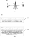
- FIG. 2 is a schematic flowchart illustrating a wireless communication method 200 according to an embodiment of the present disclosure. As shown in FIG. 2 , the method 200 may include, but not limited to, the following contents.
- a terminal device receives a handover command that instructs the terminal device to be handed over from a source cell to a target cell in a DAPS handover mode.
- the terminal device performs at least one of the following operations when the terminal device suspends at least one SRB of the source cell in accordance with the handover command: instructing a PDCP entity corresponding to the at least one SRB to suspend the PDCP entity, re-establishing an RLC entity corresponding to the at least one SRB, and triggering an SDU deletion process.
- a source base station serves the source cell
- a target base station serves the target cell
- the handover command may also be referred to as RRC reconfiguration information.
- the terminal device will maintain protocol stacks of both the source cell and the target cell during the DAPS handover.
- the handover command may be transmitted by the source base station. That is, the above step S210 may specifically include: the terminal device receiving the handover command transmitted by the source base station.
- the terminal device may suspend at least one SRB of the source cell in accordance with the handover command, and the terminal device may also initiate a synchronization process/random access to the target cell in accordance with the handover command.
- the random access may be a two-step random access or a four-step random access.
- the embodiment of the present disclosure may be applied to licensed frequency bands or unlicensed frequency bands, and the present disclosure is not limited to any of these examples.
- suspend may also be expressed as pause, or any other words with similar meanings.
- the at least one SRB may be all SRBs of the source cell, or may be some of the SRBs of the source cell, and the present disclosure is not limited to any of these examples.
- the terminal device when the terminal device suspends the at least one SRB of the source cell in accordance with the handover command, the terminal device may instruct a PDCP entity corresponding to the at least one SRB to suspend the PDCP entity. That is, the terminal device can process old RRC messages buffered in the PDCP entity of the source cell during the DAPS handover process.
- the terminal device when the terminal device suspends the at least one SRB of the source cell in accordance with the handover command, the terminal device may re-establish an RLC entity corresponding to the at least one SRB. That is, the terminal device can process old RRC messages buffered in the RLC entity of the source cell during the DAPS handover process.
- the terminal device may trigger a PDCP SDU deletion process. That is, the terminal device can delete old RRC messages buffered in the PDCP SDU of the source cell during the DAPS handover process.
- the terminal device when the terminal device instructs the PDCP entity corresponding to the at least one SRB to suspend the PDCP entity, the terminal device may delete all PDCP Protocol Data Units (PDUs) and/or PDCP SDUs of the PDCP entity corresponding to the at least one SRB.
- PDUs PDCP Protocol Data Units
- the terminal device may instruct the PDCP entity corresponding to the at least one SRB to suspend the PDCP entity and delete old RRC messages buffered in all PDCP PDUs and/or PDCP SDUs of the PDCP entity corresponding to the at least one SRB during the DAPS handover process.
- the terminal device may further reset state information of the PDCP entity corresponding to the at least one SRB.
- the terminal device may reset a timer configured in the PDCP entity corresponding to the at least one SRB, and/or the terminal device may initialize a state variable of the PDCP entity corresponding to the at least one SRB.
- the timer configured in the PDCP entity corresponding to the at least one SRB may be a timer used for deletion and/or ordering.
- Example 2 when the terminal device re-establishes the RLC entity corresponding to the at least one SRB, the terminal device may delete all data in a buffer of the RLC entity corresponding to the at least one SRB.
- all the data may include at least one of all RLC SDUs, all RLC PDUs, or RLC SDU segments.
- the terminal device may re-establish the RLC entity corresponding to the at least one SRB, and delete all data in the buffer of the RLC entity corresponding to the at least one SRB during the DAPS handover process, i.e., delete all buffered old RRC messages in the RLC entity.
- the terminal device may reset state information of the RLC entity corresponding to the at least one SRB.
- the terminal device may reset a timer configured in the RLC entity corresponding to the at least one SRB, and/or the terminal device may initialize a state variable of the RLC entity corresponding to the at least one SRB.
- the timer configured in the RLC entity corresponding to the at least one SRB may be a timer used for deletion and/or ordering.
- the terminal device when the terminal device triggers the PDCP SDU deletion process, the terminal device may delete all PDCP PDUs and/or PDCP SDUs in the PDCP entity corresponding to the at least one SRB.
- the terminal device may trigger the PDCP SDU deletion process during the DAPS handover process, and delete old RRC messages in a buffer of all PDCP PDUs and/or PDCP SDUs of the PDCP entity corresponding to the at least one SRB.
- the terminal device may perform some other operations. For example, for each SRB, one or more RLC entities may be established for the target cell using the same configuration as the source cell. In another example, for each SRB, a logical channel may be established for a target Primary Cell (PCell) using the same configuration as the source cell.
- PCell Primary Cell
- the terminal device suspends at least one SRB of the source cell in accordance with the handover command, and deletes old RRC messages buffered in the source cell, such that the terminal device can avoid transmitting unnecessary RRC messages when handed over back to the source cell after the DAPS handover fails.
- FIG. 3 is a schematic flowchart illustrating a wireless communication method 300 according to an embodiment of the present disclosure. As shown in FIG. 3 , the method 300 may include, but be not limited to, the following contents:
- a terminal device receives a handover command that instructs the terminal device to be handed over from a source cell to a target cell in a DAPS handover mode.
- the terminal device performs at least one of the following operations when the DAPS handover fails and no radio link failure in the source cell is detected: instructing a PDCP layer corresponding to at least one SRB of the source cell to suspend a PDCP entity, re-establishing an RLC entity corresponding to the at least one SRB of the source cell, and triggering a PDCP SDU deletion process.
- a source base station serves the source cell
- a target base station serves the target cell
- the handover command may also be referred to as RRC reconfiguration information.
- the terminal device will maintain protocol stacks of both the source cell and the target cell during the DAPS handover.
- the terminal device may keep monitoring a radio link of the source cell.
- the handover command may be transmitted by the source base station. That is, the above step S310 may specifically include: the terminal device receiving the handover command transmitted by the source base station.
- the terminal device may perform DAPS handover in accordance with the handover command.
- the terminal device may initiate a synchronization procedure/random access to the target cell in accordance with the handover command.
- the random access may be a two-step random access or a four-step random access.
- the embodiment of the present disclosure may be applied to licensed frequency bands or unlicensed frequency bands, and the present disclosure is not limited to any of these examples.
- the at least one SRB may be all SRBs of the source cell, or may be some of the SRBs of the source cell, and the present disclosure is not limited to any of these examples.
- the terminal device may instruct a PDCP entity corresponding to the at least one SRB to suspend the PDCP entity. That is, the terminal device can process old RRC messages buffered in the PDCP entity of the source cell during the DAPS handover process.
- the terminal device may re-establish an RLC entity corresponding to the at least one SRB. That is, the terminal device can process old RRC messages buffered in the RLC entity of the source cell during the DAPS handover process.
- the terminal device may trigger a PDCP SDU deletion process. That is, the terminal device can delete old RRC messages buffered in the PDCP SDU of the source cell during the DAPS handover process.
- Example a when the terminal device instructs the PDCP entity corresponding to the at least one SRB to suspend the PDCP entity, the terminal device may delete all PDCP PDUs and/or PDCP SDUs of the PDCP entity corresponding to the at least one SRB.
- the terminal device may instruct the PDCP entity corresponding to the at least one SRB to suspend the PDCP entity and delete old RRC messages buffered in all PDCP PDUs and/or PDCP SDUs of the PDCP entity corresponding to the at least one SRB.
- the terminal device may further reset state information of the PDCP entity corresponding to the at least one SRB.
- the terminal device may reset a timer configured in the PDCP entity corresponding to the at least one SRB, and/or the terminal device may initialize a state variable of the PDCP entity corresponding to the at least one SRB.
- the timer configured in the PDCP entity corresponding to the at least one SRB may be a timer used for deletion and/or ordering.
- Example b when the terminal device re-establishes the RLC entity corresponding to the at least one SRB, the terminal device may delete all data in a buffer of the RLC entity corresponding to the at least one SRB.
- all the data may include at least one of all RLC SDUs, all RLC PDUs, or RLC SDU segments.
- the terminal device may re-establish the RLC entity corresponding to the at least one SRB, and delete all data in the buffer of the RLC entity corresponding to the at least one SRB, i.e., delete all buffered old RRC messages in the RLC entity.
- the terminal device may reset state information of the RLC entity corresponding to the at least one SRB.
- the terminal device may reset a timer configured in the RLC entity corresponding to the at least one SRB, and/or the terminal device may initialize a state variable of the RLC entity corresponding to the at least one SRB.
- the timer configured in the RLC entity corresponding to the at least one SRB may be a timer used for deletion and/or ordering.
- the terminal device may delete all PDCP PDUs and/or PDCP SDUs in the PDCP entity corresponding to the at least one SRB.
- the terminal device may trigger the PDCP SDU deletion process, and delete old RRC messages in a buffer of all PDCP PDUs and/or PDCP SDUs of the PDCP entity corresponding to the at least one SRB.
- suspend may also be expressed as pause, or any other words with similar meanings.
- the terminal device may further resume the at least one SRB of the source cell.
- the above step S320 may be performed before the terminal device resumes the at least one SRB of the source cell, or the above step S320 may alternatively be performed after the terminal device resumes the at least one SRB of the source cell.
- the terminal device may perform some other operations before the step S320. For example, for each SRB, if no master key update is received, the terminal device may configure a PDCP entity for the source cell using the same state variable as the PDCP entity of the target cell. In another example, for each SRB, a PDCP entity of the target cell may be released. In another example, for each SRB, an RLC entity of the target cell and a logical channel associated with the target cell may be released. In another example, a physical channel configuration of the target cell may be released. In another example, a Service Data Adaptation Protocol (SDAP) configuration used in the source cell may be resumed. In another example, a key used in the target cell may be discarded.
- SDAP Service Data Adaptation Protocol
- the terminal device may perform some other operations before resuming the at least one SRB of the source cell. For example, for each SRB, if no master key update is received, the terminal device may configure a PDCP entity for the source cell using the same state variable as the PDCP entity of the target cell. In another example, for each SRB, a PDCP entity of the target cell may be released. In another example, for each SRB, an RLC entity of the target cell and a logical channel associated with the target cell may be released. In another example, a physical channel configuration of the target cell may be released. In another example, an SDAP configuration used in the source cell may be resumed. In another example, a key used in the target cell may be discarded.
- the step S320 may be performed for each SRB.
- the terminal device may instruct a PDCP layer corresponding to the at least one SRB of the source cell to suspend a PDCP entity.
- the terminal device may re-establish an RLC entity corresponding to the at least one SRB of the source cell.
- the terminal device may trigger a PDCP SDU deletion process.
- the terminal device may also perform some other operations after performing the step S320 and before resuming the at least one SRB of the source cell. For example, for each SRB, if no master key update is received, the terminal device may configure a PDCP entity for the source cell using the same state variable as the PDCP entity of the target cell. In another example, for each SRB, a PDCP entity of the target cell may be released. In another example, for each SRB, an RLC entity of the target cell and a logical channel associated with the target cell may be released. In another example, a physical channel configuration of the target cell may be released. In another example, an SDAP configuration used in the source cell may be resumed. In another example, a key used in the target cell may be discarded.
- the terminal device in the DAPS handover process, when the DAPS handover fails and no radio link failure in the source cell is detected, the terminal device can delete old RRC messages buffered in the source cell, such that the terminal device can avoid transmitting unnecessary RRC messages when handed over back to the source cell after the DAPS handover fails.
- FIG. 4 shows a schematic block diagram of a terminal device 400 according to an embodiment of the present disclosure.
- the terminal device 400 includes a communication unit 410 and a processing unit 420.
- the communication unit 410 is configured to receive a handover command that instructs the terminal device to be handed over from a source cell to a target cell in a DAPS handover mode.
- the processing unit 420 is configured to at least one of the following operations when the terminal device suspends at least one SRB of the source cell in accordance with the handover command:
- the processing unit 420 may be further configured to delete all PDCP PDUs and/or PDCP SDUs of the PDCP entity corresponding to the at least one SRB.
- the processing unit 420 may be further configured to reset state information of the PDCP entity corresponding to the at least one SRB.
- the processing unit 420 may be configured to: reset a timer configured in the PDCP entity corresponding to the at least one SRB, and/or initialize a state variable of the PDCP entity corresponding to the at least one SRB.
- the processing unit 420 may be further configured to delete all data in a buffer of the RLC entity corresponding to the at least one SRB.
- all the data may include at least one of all RLC SDUs, all RLC PDUs, or RLC SDU segments.
- the processing unit 420 may be further configured to reset state information of the RLC entity corresponding to the at least one SRB.
- the processing unit 420 may be configured to: reset a timer configured in the RLC entity corresponding to the at least one SRB, and/or initialize a state variable of the RLC entity corresponding to the at least one SRB.
- the processing unit 420 may be further configured to delete all PDCP PDUs and/or PDCP SDUs of the PDCP entity corresponding to the at least one SRB.
- the above-mentioned communication unit may be a communication interface or a transceiver, or an input/output interface of a communication chip or a system-on-chip.
- the above processing unit may be one or more processors.
- the terminal device 400 may correspond to the terminal device in the method embodiment of the present disclosure, and the above and other operations and/or functions of the various units in the terminal device 400 are provided for implementing the corresponding process performed by the terminal device in the method 200 shown in FIG. 2 , and details thereof will be omitted here for brevity.
- FIG. 5 shows a schematic block diagram of a terminal device 500 according to an embodiment of the present disclosure.
- the terminal device 500 includes: a communication unit 510 and a processing unit 520.
- the communication unit 510 is configured to receive a handover command that instructs the terminal device to be handed over from a source cell to a target cell in a DAPS handover mode.
- the processing unit 520 is configured to perform at least one of the following operations when the DAPS handover fails and no radio link failure in the source cell is detected: instructing a PDCP layer corresponding to at least one SRB of the source cell to suspend a PDCP entity, re-establishing an RLC entity corresponding to the at least one SRB of the source cell, and triggering a PDCP SDU deletion process.
- processing unit 520 may be further configured to resume the at least one SRB of the source cell.
- the processing unit 520 may be further configured to delete all PDUs and/or PDCP SDUs of the PDCP entity corresponding to the at least one SRB.
- the processing unit 520 may be further configured to reset state information of the PDCP entity corresponding to the at least one SRB.
- the processing unit 520 may be configured to reset a timer configured in the PDCP entity corresponding to the at least one SRB, and/or initialize a state variable of the PDCP entity corresponding to the at least one SRB.
- the processing unit 520 may be further configured to delete all data in a buffer of the RLC entity corresponding to the at least one SRB.
- all the data may include at least one of all RLC SDUs, all RLC PDUs, or RLC SDU segments.
- the processing unit 520 may be further configured to reset state information of the RLC entity corresponding to the at least one SRB.
- the processing unit 520 may be configured to reset a timer configured in the RLC entity corresponding to the at least one SRB, and/or initialize a state variable of the RLC entity corresponding to the at least one SRB.
- the processing unit 520 may be further configured to delete all PDCP PDUs and/or PDCP SDUs of the PDCP entity corresponding to the at least one SRB.
- the above communication unit may be a communication interface or a transceiver, or an input/output interface of a communication chip or a system-on-chip.
- the above processing unit may be one or more processors.
- the terminal device 500 may correspond to the terminal device in any of the method embodiments of the present disclosure, and the above and other operations and/or functions of the respective units in the terminal device 500 are provided to implement the corresponding process of the terminal device in the method 300 as shown in FIG. 3 .
- the terminal device 500 may correspond to the terminal device in any of the method embodiments of the present disclosure, and the above and other operations and/or functions of the respective units in the terminal device 500 are provided to implement the corresponding process of the terminal device in the method 300 as shown in FIG. 3 .
- details thereof will be omitted here.
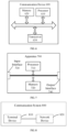
- FIG. 6 is a schematic diagram showing a structure of a communication device 600 according to an embodiment of the present disclosure.
- the communication device 600 shown in FIG. 6 includes a processor 610, and the processor 610 can invoke and execute a computer program from a memory to implement the method in the embodiment of the present disclosure.
- the communication device 600 may further include a memory 620.
- the processor 610 can invoke and execute a computer program from the memory 620 to implement the method in the embodiment of the present disclosure.
- the memory 620 may be a separate device independent from the processor 610, or may be integrated in the processor 610.
- the communication device 600 may further include a transceiver 630, and the processor 610 may control the transceiver 630 to communicate with other devices, and in particular, transmit information or data to other devices, or receive information or data transmitted by other devices.
- the transceiver 630 may include a transmitter and a receiver.
- the transceiver 630 may further include one or more antennas.
- the communication device 600 may specifically be the network device according to the embodiment of the present disclosure, and the communication device 600 may implement the corresponding processes implemented by the network device in any of the methods according to the embodiments of the present disclosure. For the sake of brevity, details thereof will be omitted here.
- the communication device 600 may specifically be the mobile terminal/terminal device according to the embodiment of the present disclosure, and the communication device 600 may implement the corresponding processes implemented by the mobile terminal/terminal device in any of the methods according to the embodiments of the present disclosure. For the sake of brevity, details thereof will be omitted here.
- FIG. 7 is a schematic diagram showing a structure of an apparatus according to an embodiment of the present disclosure.
- the apparatus 700 shown in FIG. 7 includes a processor 710, and the processor 710 can invoke and execute a computer program from a memory to implement the method in the embodiment of the present disclosure.
- the apparatus 700 may further include a memory 720.
- the processor 710 can invoke and execute a computer program from the memory 720 to implement the method in the embodiment of the present disclosure.
- the memory 720 may be a separate device independent from the processor 710, or may be integrated in the processor 710.
- the apparatus 700 may further include an input interface 730.
- the processor 710 can control the input interface 730 to communicate with other devices or chips, and in particular, obtain information or data transmitted by other devices or chips.
- the apparatus 700 may further include an output interface 740.
- the processor 710 can control the output interface 740 to communicate with other devices or chips, and in particular, output information or data to other devices or chips.
- the apparatus can be applied to the network device in the embodiment of the present disclosure, and the apparatus can implement the corresponding processes implemented by the network device in the various methods of the embodiments of the present disclosure.
- the apparatus can implement the corresponding processes implemented by the network device in the various methods of the embodiments of the present disclosure.
- details thereof will be omitted here.
- the apparatus can be applied to the mobile terminal/terminal device in the embodiment of the present disclosure, and the apparatus can implement the corresponding process implemented by the mobile terminal/terminal device in each method of the embodiment of the present disclosure.
- the apparatus can implement the corresponding process implemented by the mobile terminal/terminal device in each method of the embodiment of the present disclosure.
- details thereof will be omitted here.
- the apparatus in the embodiment of the present disclosure may be a chip, and the chip may also be referred to as a system-level chip, a system-chip, a chip system, or a system-on-chip.
- FIG. 8 is a schematic block diagram showing a communication system 800 according to an embodiment of the present disclosure. As shown in FIG. 8 , the communication system 800 includes a terminal device 810 and a network device 820.
- the terminal device 810 can be configured to implement the corresponding functions implemented by the terminal device in the above method
- the network device 820 can be configured to implement the corresponding functions implemented by the network device in the above method.
- details thereof will be omitted here.
- the processor in the embodiment of the present disclosure may be an integrated circuit chip with signal processing capability.
- the steps of the above method embodiments can be implemented by hardware integrated logic circuits in a processor or instructions in the form of software.
- the processor can be a general purpose processor, a Digital Signal Processor (DSP), an Application Specific Integrated Circuit (ASIC), a Field Programmable Gate Array (FPGA) or another programmable logic device, a discrete gate or transistor logic device, or a discrete hardware component.
- DSP Digital Signal Processor
- ASIC Application Specific Integrated Circuit
- FPGA Field Programmable Gate Array
- the methods, steps, and logical block diagrams disclosed in the embodiments of the present disclosure can be implemented or performed.
- the general purpose processor may be a microprocessor or any conventional processor.
- the steps of the methods disclosed in the embodiments of the present disclosure may be directly embodied as being performed and completed by a hardware decoding processor, or by a combination of hardware and software modules in the decoding processor.
- the software modules can be located in a known storage medium in the related art, such as random access memory, flash memory, read-only memory, programmable read-only memory, electrically erasable programmable memory, or register.
- the storage medium can be located in the memory, and the processor can read information from the memory and perform the steps of the above methods in combination with its hardware.
- the memory in the embodiments of the present disclosure may be a volatile memory or a non-volatile memory, or may include both volatile and non-volatile memories.
- the non-volatile memory may be a Read-Only Memory (ROM), a Programmable ROM (PROM), an Erasable PROM (EPROM), an Electrically EPROM (EEPROM), or a flash memory.
- the volatile memory may be a Random Access Memory (RAM), which is used as an external cache.
- RAM Random Rambus RAM
- DRAM Static RAM
- DRAM Dynamic RAM
- SDRAM Synchronous DRAM
- DDR SDRAM Double Data Rate SDRAM
- ESDRAM Enhanced SDRAM
- SLDRAM Synchlink DRAM
- DR RAM Direct Rambus RAM
- the above memories are exemplary only, rather than limiting the present disclosure.
- the memory in the embodiment of the present disclosure may also be a Static RAM (SRAM), a Dynamic RAM (DRAM), a Synchronous DRAM (SDRAM), a Double Data Rate SDRAM (DDR SDRAM), an Enhanced SDRAM (ESDRAM), a Synch Link DRAM (SLDRAM), or a Direct Rambus RAM (DR RAM). That is, the memory in the embodiments of the present disclosure is intended to include, but not limited to, these and any other suitable types of memories.
- SRAM Static RAM
- DRAM Dynamic RAM
- SDRAM Synchronous DRAM
- DDR SDRAM Double Data Rate SDRAM
- ESDRAM Enhanced SDRAM
- SLDRAM Synch Link DRAM
- DR RAM Direct Rambus RAM
- An embodiment of the present disclosure also provides a computer readable storage medium having a computer program stored thereon.
- the computer readable storage medium can be applied to the network device in the embodiment of the present disclosure, and the computer program can cause a computer to perform corresponding procedures implemented by the network device in the method according to any of the embodiments of the present disclosure. Details thereof will be omitted here for simplicity.
- the computer readable storage medium can be applied to the mobile terminal/terminal device in the embodiment of the present disclosure, and the computer program can cause a computer to perform corresponding procedures implemented by the mobile terminal/terminal device in the method according to any of the embodiments of the present disclosure. Details thereof will be omitted here for simplicity.
- An embodiment of the present disclosure also provides a computer program product including computer program instructions.
- the computer program product can be applied to the network device in the embodiment of the present disclosure, and the computer program instructions can cause a computer to perform corresponding procedures implemented by the network device in the method according to any of the embodiments of the present disclosure. Details thereof will be omitted here for simplicity.
- the computer program product can be applied to the mobile terminal/terminal device in the embodiment of the present disclosure, and the computer program instructions can cause a computer to perform corresponding procedures implemented by the mobile terminal/terminal device in the method according to any of the embodiments of the present disclosure. Details thereof will be omitted here for simplicity.
- An embodiment of the present disclosure also provides a computer program.
- the computer program can be applied to the network device in the embodiment of the present disclosure.
- the computer program when executed by a computer, can cause the computer to perform corresponding procedures implemented by the network device in the method according to any of the embodiments of the present disclosure. Details thereof will be omitted here for simplicity.
- the computer program can be applied to the mobile terminal/terminal device in the embodiment of the present disclosure.
- the computer program when executed by a computer, can cause the computer to perform corresponding procedures implemented by the mobile terminal/terminal device in the method according to any of the embodiments of the present disclosure. Details thereof will be omitted here for simplicity.
- the disclosed systems, devices, and methods may be implemented in other ways.
- the device embodiments described above are illustrative only.
- the divisions of the units are only divisions based on logical functions, and there may be other divisions in actual implementations.
- more than one unit or component may be combined or integrated into another system, or some features can be ignored or omitted.
- the mutual coupling or direct coupling or communicative connection as shown or discussed may be indirect coupling or communicative connection between devices or units via some interfaces which may be electrical, mechanical, or in any other forms.
- the units described as separate components may or may not be physically separated, and the components shown as units may or may not be physical units, that is, they may be co-located or distributed across a number of network elements. Some or all of the units may be selected according to actual needs to achieve the objects of the solutions of the embodiments.
- the functional units in the embodiments of the present disclosure may be integrated into one processing unit, or alternatively be separate physical modules, or two or more units may be integrated into one unit.
- the computer software product may be stored in a storage medium and contain instructions to cause a computer device, such as a personal computer, a server, or a network device, etc., to perform all or part of the steps of the method described in each of the embodiments of the present disclosure.
- the storage medium may include a Universal Serial Bus flash drive, a mobile hard disk, a Read-Only Memory (ROM), a Random Access Memory (RAM), a magnetic disk, an optical disc, or any other medium capable of storing program codes.
Landscapes
- Engineering & Computer Science (AREA)
- Computer Networks & Wireless Communication (AREA)
- Signal Processing (AREA)
- Mobile Radio Communication Systems (AREA)
Priority Applications (1)
| Application Number | Priority Date | Filing Date | Title |
|---|---|---|---|
| EP25178693.5A EP4583625A3 (fr) | 2020-05-21 | 2020-09-03 | Procédé de communication radio et dispositif terminal |
Applications Claiming Priority (2)
| Application Number | Priority Date | Filing Date | Title |
|---|---|---|---|
| CN202010438172.2A CN113709825A (zh) | 2020-05-21 | 2020-05-21 | 无线通信方法和终端设备 |
| PCT/CN2020/113238 WO2021232617A1 (fr) | 2020-05-21 | 2020-09-03 | Procédé de radiocommunication et dispositif terminal |
Related Child Applications (2)
| Application Number | Title | Priority Date | Filing Date |
|---|---|---|---|
| EP25178693.5A Division EP4583625A3 (fr) | 2020-05-21 | 2020-09-03 | Procédé de communication radio et dispositif terminal |
| EP25178693.5A Division-Into EP4583625A3 (fr) | 2020-05-21 | 2020-09-03 | Procédé de communication radio et dispositif terminal |
Publications (3)
| Publication Number | Publication Date |
|---|---|
| EP4156841A1 true EP4156841A1 (fr) | 2023-03-29 |
| EP4156841A4 EP4156841A4 (fr) | 2023-11-15 |
| EP4156841B1 EP4156841B1 (fr) | 2025-07-02 |
Family
ID=78645955
Family Applications (2)
| Application Number | Title | Priority Date | Filing Date |
|---|---|---|---|
| EP20936143.5A Active EP4156841B1 (fr) | 2020-05-21 | 2020-09-03 | Procédé de radiocommunication et dispositif terminal |
| EP25178693.5A Pending EP4583625A3 (fr) | 2020-05-21 | 2020-09-03 | Procédé de communication radio et dispositif terminal |
Family Applications After (1)
| Application Number | Title | Priority Date | Filing Date |
|---|---|---|---|
| EP25178693.5A Pending EP4583625A3 (fr) | 2020-05-21 | 2020-09-03 | Procédé de communication radio et dispositif terminal |
Country Status (5)
| Country | Link |
|---|---|
| US (1) | US20230080024A1 (fr) |
| EP (2) | EP4156841B1 (fr) |
| CN (2) | CN113709825A (fr) |
| ES (1) | ES3037004T3 (fr) |
| WO (1) | WO2021232617A1 (fr) |
Families Citing this family (3)
| Publication number | Priority date | Publication date | Assignee | Title |
|---|---|---|---|---|
| CN114339914B (zh) * | 2021-12-31 | 2024-11-08 | 哲库科技(北京)有限公司 | 小区切换方法、装置、网络设备及存储介质 |
| CN116567743A (zh) * | 2022-01-30 | 2023-08-08 | 华为技术有限公司 | 一种通信方法及装置 |
| CN121728523A (zh) * | 2024-09-23 | 2026-03-24 | 维沃移动通信有限公司 | 数据传输方法、装置、终端、网络侧设备及可读存储介质 |
Family Cites Families (7)
| Publication number | Priority date | Publication date | Assignee | Title |
|---|---|---|---|---|
| WO2018050958A1 (fr) * | 2016-09-13 | 2018-03-22 | Nokia Technologies Oy | Gestion de comptage de pdcp dans une reprise de connexion rrc |
| CN110831250B (zh) * | 2018-08-07 | 2022-02-08 | 维沃移动通信有限公司 | 一种处理方法及终端 |
| CN113940113B (zh) * | 2019-05-03 | 2023-12-29 | Lg电子株式会社 | 针对无线通信系统中的无线电资源管理的方法和设备 |
| JP7717689B2 (ja) * | 2019-10-02 | 2025-08-04 | サムスン エレクトロニクス カンパニー リミテッド | 無線通信システムにおいてハンドオーバー手続きを実行する方法及びその装置 |
| KR102854564B1 (ko) * | 2019-11-01 | 2025-09-03 | 삼성전자 주식회사 | 차세대 이동 통신 시스템의 daps 핸드오버에서 pdcp 엔티티를 구동하는 방법 및 장치 |
| CN118354377A (zh) * | 2020-02-13 | 2024-07-16 | 瑞典爱立信有限公司 | 无线电网络节点、用户设备(ue)及其中执行的方法 |
| KR20230005277A (ko) * | 2020-04-30 | 2023-01-09 | 구글 엘엘씨 | 핸드오버 실패 시나리오에서 네트워크 최적화 관리 |
-
2020
- 2020-05-21 CN CN202010438172.2A patent/CN113709825A/zh active Pending
- 2020-05-21 CN CN202411486475.6A patent/CN119342542A/zh active Pending
- 2020-09-03 ES ES20936143T patent/ES3037004T3/es active Active
- 2020-09-03 EP EP20936143.5A patent/EP4156841B1/fr active Active
- 2020-09-03 EP EP25178693.5A patent/EP4583625A3/fr active Pending
- 2020-09-03 WO PCT/CN2020/113238 patent/WO2021232617A1/fr not_active Ceased
-
2022
- 2022-11-18 US US17/990,376 patent/US20230080024A1/en active Pending
Also Published As
| Publication number | Publication date |
|---|---|
| CN119342542A (zh) | 2025-01-21 |
| US20230080024A1 (en) | 2023-03-16 |
| WO2021232617A1 (fr) | 2021-11-25 |
| CN113709825A (zh) | 2021-11-26 |
| EP4583625A3 (fr) | 2025-09-24 |
| EP4583625A2 (fr) | 2025-07-09 |
| EP4156841A4 (fr) | 2023-11-15 |
| EP4156841B1 (fr) | 2025-07-02 |
| ES3037004T3 (en) | 2025-09-26 |
Similar Documents
| Publication | Publication Date | Title |
|---|---|---|
| US20230009565A1 (en) | Communication method and apparatus applied to multi-link device in wireless local area network | |
| US20230012998A1 (en) | Communication method, access network device, terminal device, and core network device | |
| US20230080024A1 (en) | Wireless communication method and terminal device | |
| EP4161151B1 (fr) | Procédés de communication sans fil, dispositif terminal et dispositif de réseau | |
| US12439329B2 (en) | Handover method and device | |
| US20240259904A1 (en) | Wireless communication method, terminal device, and network device | |
| US12543174B2 (en) | Data transmission method and terminal device | |
| US20250024334A1 (en) | Wireless communication method, network device, and terminal device | |
| EP4243476A1 (fr) | Procédé de communication sans fil et équipement terminal | |
| US12414198B2 (en) | Secondary node change method, terminal device and network device | |
| US12490320B2 (en) | Data transmission method and network device | |
| WO2023065156A1 (fr) | Procédé de communication sans fil, dispositif terminal et dispositif de réseau | |
| US20250063611A1 (en) | Connection configuration method and terminal | |
| US20240422851A1 (en) | Wireless communication method and terminal devices | |
| US20250098010A1 (en) | Wireless communication method, terminal device, and network device | |
| WO2025180303A1 (fr) | Procédé de transfert intercellulaire, appareil et système de communication | |
| WO2024000583A1 (fr) | Procédé de traitement de ressources, équipement terminal et dispositif de réseau |
Legal Events
| Date | Code | Title | Description |
|---|---|---|---|
| STAA | Information on the status of an ep patent application or granted ep patent |
Free format text: STATUS: THE INTERNATIONAL PUBLICATION HAS BEEN MADE |
|
| PUAI | Public reference made under article 153(3) epc to a published international application that has entered the european phase |
Free format text: ORIGINAL CODE: 0009012 |
|
| STAA | Information on the status of an ep patent application or granted ep patent |
Free format text: STATUS: REQUEST FOR EXAMINATION WAS MADE |
|
| 17P | Request for examination filed |
Effective date: 20221219 |
|
| AK | Designated contracting states |
Kind code of ref document: A1 Designated state(s): AL AT BE BG CH CY CZ DE DK EE ES FI FR GB GR HR HU IE IS IT LI LT LU LV MC MK MT NL NO PL PT RO RS SE SI SK SM TR |
|
| DAV | Request for validation of the european patent (deleted) | ||
| DAX | Request for extension of the european patent (deleted) | ||
| A4 | Supplementary search report drawn up and despatched |
Effective date: 20231016 |
|
| RIC1 | Information provided on ipc code assigned before grant |
Ipc: H04W 76/10 20180101AFI20231010BHEP |
|
| STAA | Information on the status of an ep patent application or granted ep patent |
Free format text: STATUS: EXAMINATION IS IN PROGRESS |
|
| 17Q | First examination report despatched |
Effective date: 20240705 |
|
| REG | Reference to a national code |
Ref country code: DE Ref legal event code: R079 Free format text: PREVIOUS MAIN CLASS: H04W0076100000 Ipc: H04W0036000000 Ref document number: 602020054039 Country of ref document: DE |
|
| GRAP | Despatch of communication of intention to grant a patent |
Free format text: ORIGINAL CODE: EPIDOSNIGR1 |
|
| STAA | Information on the status of an ep patent application or granted ep patent |
Free format text: STATUS: GRANT OF PATENT IS INTENDED |
|
| RIC1 | Information provided on ipc code assigned before grant |
Ipc: H04W 76/10 20180101ALI20250109BHEP Ipc: H04W 36/00 20090101AFI20250109BHEP |
|
| INTG | Intention to grant announced |
Effective date: 20250127 |
|
| GRAS | Grant fee paid |
Free format text: ORIGINAL CODE: EPIDOSNIGR3 |
|
| GRAA | (expected) grant |
Free format text: ORIGINAL CODE: 0009210 |
|
| STAA | Information on the status of an ep patent application or granted ep patent |
Free format text: STATUS: THE PATENT HAS BEEN GRANTED |
|
| AK | Designated contracting states |
Kind code of ref document: B1 Designated state(s): AL AT BE BG CH CY CZ DE DK EE ES FI FR GB GR HR HU IE IS IT LI LT LU LV MC MK MT NL NO PL PT RO RS SE SI SK SM TR |
|
| REG | Reference to a national code |
Ref country code: GB Ref legal event code: FG4D |
|
| REG | Reference to a national code |
Ref country code: CH Ref legal event code: EP |
|
| REG | Reference to a national code |
Ref country code: DE Ref legal event code: R096 Ref document number: 602020054039 Country of ref document: DE |
|
| REG | Reference to a national code |
Ref country code: IE Ref legal event code: FG4D |
|
| REG | Reference to a national code |
Ref country code: NL Ref legal event code: FP |
|
| REG | Reference to a national code |
Ref country code: ES Ref legal event code: FG2A Ref document number: 3037004 Country of ref document: ES Kind code of ref document: T3 Effective date: 20250926 |
|
| P01 | Opt-out of the competence of the unified patent court (upc) registered |
Free format text: CASE NUMBER: UPC_APP_5173_4156841/2025 Effective date: 20250829 |
|
| PGFP | Annual fee paid to national office [announced via postgrant information from national office to epo] |
Ref country code: DE Payment date: 20250919 Year of fee payment: 6 |
|
| PGFP | Annual fee paid to national office [announced via postgrant information from national office to epo] |
Ref country code: NL Payment date: 20250922 Year of fee payment: 6 |
|
| PGFP | Annual fee paid to national office [announced via postgrant information from national office to epo] |
Ref country code: GB Payment date: 20250923 Year of fee payment: 6 |
|
| PGFP | Annual fee paid to national office [announced via postgrant information from national office to epo] |
Ref country code: FR Payment date: 20250924 Year of fee payment: 6 |
|
| PG25 | Lapsed in a contracting state [announced via postgrant information from national office to epo] |
Ref country code: PT Free format text: LAPSE BECAUSE OF FAILURE TO SUBMIT A TRANSLATION OF THE DESCRIPTION OR TO PAY THE FEE WITHIN THE PRESCRIBED TIME-LIMIT Effective date: 20251103 |
|
| REG | Reference to a national code |
Ref country code: AT Ref legal event code: MK05 Ref document number: 1810726 Country of ref document: AT Kind code of ref document: T Effective date: 20250702 |
|
| PG25 | Lapsed in a contracting state [announced via postgrant information from national office to epo] |
Ref country code: IS Free format text: LAPSE BECAUSE OF FAILURE TO SUBMIT A TRANSLATION OF THE DESCRIPTION OR TO PAY THE FEE WITHIN THE PRESCRIBED TIME-LIMIT Effective date: 20251102 |
|
| PG25 | Lapsed in a contracting state [announced via postgrant information from national office to epo] |
Ref country code: NO Free format text: LAPSE BECAUSE OF FAILURE TO SUBMIT A TRANSLATION OF THE DESCRIPTION OR TO PAY THE FEE WITHIN THE PRESCRIBED TIME-LIMIT Effective date: 20251002 |
|
| REG | Reference to a national code |
Ref country code: LT Ref legal event code: MG9D |
|
| PG25 | Lapsed in a contracting state [announced via postgrant information from national office to epo] |
Ref country code: AT Free format text: LAPSE BECAUSE OF FAILURE TO SUBMIT A TRANSLATION OF THE DESCRIPTION OR TO PAY THE FEE WITHIN THE PRESCRIBED TIME-LIMIT Effective date: 20250702 |
|
| PG25 | Lapsed in a contracting state [announced via postgrant information from national office to epo] |
Ref country code: FI Free format text: LAPSE BECAUSE OF FAILURE TO SUBMIT A TRANSLATION OF THE DESCRIPTION OR TO PAY THE FEE WITHIN THE PRESCRIBED TIME-LIMIT Effective date: 20250702 |
|
| PGFP | Annual fee paid to national office [announced via postgrant information from national office to epo] |
Ref country code: IT Payment date: 20251029 Year of fee payment: 6 |
|
| PG25 | Lapsed in a contracting state [announced via postgrant information from national office to epo] |
Ref country code: HR Free format text: LAPSE BECAUSE OF FAILURE TO SUBMIT A TRANSLATION OF THE DESCRIPTION OR TO PAY THE FEE WITHIN THE PRESCRIBED TIME-LIMIT Effective date: 20250702 |
|
| PG25 | Lapsed in a contracting state [announced via postgrant information from national office to epo] |
Ref country code: GR Free format text: LAPSE BECAUSE OF FAILURE TO SUBMIT A TRANSLATION OF THE DESCRIPTION OR TO PAY THE FEE WITHIN THE PRESCRIBED TIME-LIMIT Effective date: 20251003 |
|
| PG25 | Lapsed in a contracting state [announced via postgrant information from national office to epo] |
Ref country code: SE Free format text: LAPSE BECAUSE OF FAILURE TO SUBMIT A TRANSLATION OF THE DESCRIPTION OR TO PAY THE FEE WITHIN THE PRESCRIBED TIME-LIMIT Effective date: 20250702 Ref country code: CZ Free format text: LAPSE BECAUSE OF FAILURE TO SUBMIT A TRANSLATION OF THE DESCRIPTION OR TO PAY THE FEE WITHIN THE PRESCRIBED TIME-LIMIT Effective date: 20250702 |
|
| PG25 | Lapsed in a contracting state [announced via postgrant information from national office to epo] |
Ref country code: LV Free format text: LAPSE BECAUSE OF FAILURE TO SUBMIT A TRANSLATION OF THE DESCRIPTION OR TO PAY THE FEE WITHIN THE PRESCRIBED TIME-LIMIT Effective date: 20250702 |
|
| PG25 | Lapsed in a contracting state [announced via postgrant information from national office to epo] |
Ref country code: BG Free format text: LAPSE BECAUSE OF FAILURE TO SUBMIT A TRANSLATION OF THE DESCRIPTION OR TO PAY THE FEE WITHIN THE PRESCRIBED TIME-LIMIT Effective date: 20250702 Ref country code: PL Free format text: LAPSE BECAUSE OF FAILURE TO SUBMIT A TRANSLATION OF THE DESCRIPTION OR TO PAY THE FEE WITHIN THE PRESCRIBED TIME-LIMIT Effective date: 20250702 |
|
| PG25 | Lapsed in a contracting state [announced via postgrant information from national office to epo] |
Ref country code: RS Free format text: LAPSE BECAUSE OF FAILURE TO SUBMIT A TRANSLATION OF THE DESCRIPTION OR TO PAY THE FEE WITHIN THE PRESCRIBED TIME-LIMIT Effective date: 20251002 |
|
| PGFP | Annual fee paid to national office [announced via postgrant information from national office to epo] |
Ref country code: ES Payment date: 20251020 Year of fee payment: 6 |
|
| PG25 | Lapsed in a contracting state [announced via postgrant information from national office to epo] |
Ref country code: RO Free format text: LAPSE BECAUSE OF FAILURE TO SUBMIT A TRANSLATION OF THE DESCRIPTION OR TO PAY THE FEE WITHIN THE PRESCRIBED TIME-LIMIT Effective date: 20250702 |
|
| PG25 | Lapsed in a contracting state [announced via postgrant information from national office to epo] |
Ref country code: SM Free format text: LAPSE BECAUSE OF FAILURE TO SUBMIT A TRANSLATION OF THE DESCRIPTION OR TO PAY THE FEE WITHIN THE PRESCRIBED TIME-LIMIT Effective date: 20250702 |
|
| PG25 | Lapsed in a contracting state [announced via postgrant information from national office to epo] |
Ref country code: DK Free format text: LAPSE BECAUSE OF FAILURE TO SUBMIT A TRANSLATION OF THE DESCRIPTION OR TO PAY THE FEE WITHIN THE PRESCRIBED TIME-LIMIT Effective date: 20250702 |
|
| PG25 | Lapsed in a contracting state [announced via postgrant information from national office to epo] |
Ref country code: SK Free format text: LAPSE BECAUSE OF FAILURE TO SUBMIT A TRANSLATION OF THE DESCRIPTION OR TO PAY THE FEE WITHIN THE PRESCRIBED TIME-LIMIT Effective date: 20250702 Ref country code: EE Free format text: LAPSE BECAUSE OF FAILURE TO SUBMIT A TRANSLATION OF THE DESCRIPTION OR TO PAY THE FEE WITHIN THE PRESCRIBED TIME-LIMIT Effective date: 20250702 |