EP4157665B1 - Verfahren zur abschätzung des ladezustands einer batterie insbesondere zur wiederaufladensverwaltung von elektrofahrzeugen - Google Patents
Verfahren zur abschätzung des ladezustands einer batterie insbesondere zur wiederaufladensverwaltung von elektrofahrzeugen Download PDFInfo
- Publication number
- EP4157665B1 EP4157665B1 EP21732378.1A EP21732378A EP4157665B1 EP 4157665 B1 EP4157665 B1 EP 4157665B1 EP 21732378 A EP21732378 A EP 21732378A EP 4157665 B1 EP4157665 B1 EP 4157665B1
- Authority
- EP
- European Patent Office
- Prior art keywords
- soc
- charge
- state
- electric
- data
- Prior art date
- Legal status (The legal status is an assumption and is not a legal conclusion. Google has not performed a legal analysis and makes no representation as to the accuracy of the status listed.)
- Active
Links
Images


Classifications
-
- B—PERFORMING OPERATIONS; TRANSPORTING
- B60—VEHICLES IN GENERAL
- B60L—PROPULSION OF ELECTRICALLY-PROPELLED VEHICLES; SUPPLYING ELECTRIC POWER FOR AUXILIARY EQUIPMENT OF ELECTRICALLY-PROPELLED VEHICLES; ELECTRODYNAMIC BRAKE SYSTEMS FOR VEHICLES IN GENERAL; MAGNETIC SUSPENSION OR LEVITATION FOR VEHICLES; MONITORING OPERATING VARIABLES OF ELECTRICALLY-PROPELLED VEHICLES; ELECTRIC SAFETY DEVICES FOR ELECTRICALLY-PROPELLED VEHICLES
- B60L53/00—Methods of charging batteries, specially adapted for electric vehicles; Charging stations or on-board charging equipment therefor; Exchange of energy storage elements in electric vehicles
- B60L53/60—Monitoring or controlling charging stations
- B60L53/65—Monitoring or controlling charging stations involving identification of vehicles or their battery types
-
- B—PERFORMING OPERATIONS; TRANSPORTING
- B60—VEHICLES IN GENERAL
- B60L—PROPULSION OF ELECTRICALLY-PROPELLED VEHICLES; SUPPLYING ELECTRIC POWER FOR AUXILIARY EQUIPMENT OF ELECTRICALLY-PROPELLED VEHICLES; ELECTRODYNAMIC BRAKE SYSTEMS FOR VEHICLES IN GENERAL; MAGNETIC SUSPENSION OR LEVITATION FOR VEHICLES; MONITORING OPERATING VARIABLES OF ELECTRICALLY-PROPELLED VEHICLES; ELECTRIC SAFETY DEVICES FOR ELECTRICALLY-PROPELLED VEHICLES
- B60L3/00—Electric devices on electrically-propelled vehicles for safety purposes; Monitoring operating variables, e.g. speed, deceleration or energy consumption
- B60L3/12—Recording operating variables ; Monitoring of operating variables
-
- B—PERFORMING OPERATIONS; TRANSPORTING
- B60—VEHICLES IN GENERAL
- B60L—PROPULSION OF ELECTRICALLY-PROPELLED VEHICLES; SUPPLYING ELECTRIC POWER FOR AUXILIARY EQUIPMENT OF ELECTRICALLY-PROPELLED VEHICLES; ELECTRODYNAMIC BRAKE SYSTEMS FOR VEHICLES IN GENERAL; MAGNETIC SUSPENSION OR LEVITATION FOR VEHICLES; MONITORING OPERATING VARIABLES OF ELECTRICALLY-PROPELLED VEHICLES; ELECTRIC SAFETY DEVICES FOR ELECTRICALLY-PROPELLED VEHICLES
- B60L53/00—Methods of charging batteries, specially adapted for electric vehicles; Charging stations or on-board charging equipment therefor; Exchange of energy storage elements in electric vehicles
- B60L53/60—Monitoring or controlling charging stations
- B60L53/66—Data transfer between charging stations and vehicles
- B60L53/665—Methods related to measuring, billing or payment
-
- B—PERFORMING OPERATIONS; TRANSPORTING
- B60—VEHICLES IN GENERAL
- B60L—PROPULSION OF ELECTRICALLY-PROPELLED VEHICLES; SUPPLYING ELECTRIC POWER FOR AUXILIARY EQUIPMENT OF ELECTRICALLY-PROPELLED VEHICLES; ELECTRODYNAMIC BRAKE SYSTEMS FOR VEHICLES IN GENERAL; MAGNETIC SUSPENSION OR LEVITATION FOR VEHICLES; MONITORING OPERATING VARIABLES OF ELECTRICALLY-PROPELLED VEHICLES; ELECTRIC SAFETY DEVICES FOR ELECTRICALLY-PROPELLED VEHICLES
- B60L58/00—Methods or circuit arrangements for monitoring or controlling batteries or fuel cells, specially adapted for electric vehicles
- B60L58/10—Methods or circuit arrangements for monitoring or controlling batteries or fuel cells, specially adapted for electric vehicles for monitoring or controlling batteries
- B60L58/12—Methods or circuit arrangements for monitoring or controlling batteries or fuel cells, specially adapted for electric vehicles for monitoring or controlling batteries responding to state of charge [SoC]
-
- B—PERFORMING OPERATIONS; TRANSPORTING
- B60—VEHICLES IN GENERAL
- B60L—PROPULSION OF ELECTRICALLY-PROPELLED VEHICLES; SUPPLYING ELECTRIC POWER FOR AUXILIARY EQUIPMENT OF ELECTRICALLY-PROPELLED VEHICLES; ELECTRODYNAMIC BRAKE SYSTEMS FOR VEHICLES IN GENERAL; MAGNETIC SUSPENSION OR LEVITATION FOR VEHICLES; MONITORING OPERATING VARIABLES OF ELECTRICALLY-PROPELLED VEHICLES; ELECTRIC SAFETY DEVICES FOR ELECTRICALLY-PROPELLED VEHICLES
- B60L58/00—Methods or circuit arrangements for monitoring or controlling batteries or fuel cells, specially adapted for electric vehicles
- B60L58/10—Methods or circuit arrangements for monitoring or controlling batteries or fuel cells, specially adapted for electric vehicles for monitoring or controlling batteries
- B60L58/16—Methods or circuit arrangements for monitoring or controlling batteries or fuel cells, specially adapted for electric vehicles for monitoring or controlling batteries responding to battery ageing, e.g. to the number of charging cycles or the state of health [SoH]
-
- G—PHYSICS
- G01—MEASURING; TESTING
- G01R—MEASURING ELECTRIC VARIABLES; MEASURING MAGNETIC VARIABLES
- G01R31/00—Arrangements for testing electric properties; Arrangements for locating electric faults; Arrangements for electrical testing characterised by what is being tested not provided for elsewhere
- G01R31/36—Arrangements for testing, measuring or monitoring the electrical condition of accumulators or electric batteries, e.g. capacity or state of charge [SoC]
- G01R31/367—Software therefor, e.g. for battery testing using modelling or look-up tables
-
- G—PHYSICS
- G01—MEASURING; TESTING
- G01R—MEASURING ELECTRIC VARIABLES; MEASURING MAGNETIC VARIABLES
- G01R31/00—Arrangements for testing electric properties; Arrangements for locating electric faults; Arrangements for electrical testing characterised by what is being tested not provided for elsewhere
- G01R31/36—Arrangements for testing, measuring or monitoring the electrical condition of accumulators or electric batteries, e.g. capacity or state of charge [SoC]
- G01R31/382—Arrangements for monitoring battery or accumulator variables, e.g. SoC
-
- H—ELECTRICITY
- H01—ELECTRIC ELEMENTS
- H01M—PROCESSES OR MEANS, e.g. BATTERIES, FOR THE DIRECT CONVERSION OF CHEMICAL ENERGY INTO ELECTRICAL ENERGY
- H01M10/00—Secondary cells; Manufacture thereof
- H01M10/42—Methods or arrangements for servicing or maintenance of secondary cells or secondary half-cells
- H01M10/44—Methods for charging or discharging
-
- H—ELECTRICITY
- H01—ELECTRIC ELEMENTS
- H01M—PROCESSES OR MEANS, e.g. BATTERIES, FOR THE DIRECT CONVERSION OF CHEMICAL ENERGY INTO ELECTRICAL ENERGY
- H01M10/00—Secondary cells; Manufacture thereof
- H01M10/42—Methods or arrangements for servicing or maintenance of secondary cells or secondary half-cells
- H01M10/48—Accumulators combined with arrangements for measuring, testing or indicating the condition of cells, e.g. the level or density of the electrolyte
-
- B—PERFORMING OPERATIONS; TRANSPORTING
- B60—VEHICLES IN GENERAL
- B60L—PROPULSION OF ELECTRICALLY-PROPELLED VEHICLES; SUPPLYING ELECTRIC POWER FOR AUXILIARY EQUIPMENT OF ELECTRICALLY-PROPELLED VEHICLES; ELECTRODYNAMIC BRAKE SYSTEMS FOR VEHICLES IN GENERAL; MAGNETIC SUSPENSION OR LEVITATION FOR VEHICLES; MONITORING OPERATING VARIABLES OF ELECTRICALLY-PROPELLED VEHICLES; ELECTRIC SAFETY DEVICES FOR ELECTRICALLY-PROPELLED VEHICLES
- B60L2240/00—Control parameters of input or output; Target parameters
- B60L2240/70—Interactions with external data bases, e.g. traffic centres
-
- B—PERFORMING OPERATIONS; TRANSPORTING
- B60—VEHICLES IN GENERAL
- B60L—PROPULSION OF ELECTRICALLY-PROPELLED VEHICLES; SUPPLYING ELECTRIC POWER FOR AUXILIARY EQUIPMENT OF ELECTRICALLY-PROPELLED VEHICLES; ELECTRODYNAMIC BRAKE SYSTEMS FOR VEHICLES IN GENERAL; MAGNETIC SUSPENSION OR LEVITATION FOR VEHICLES; MONITORING OPERATING VARIABLES OF ELECTRICALLY-PROPELLED VEHICLES; ELECTRIC SAFETY DEVICES FOR ELECTRICALLY-PROPELLED VEHICLES
- B60L2260/00—Operating Modes
- B60L2260/40—Control modes
- B60L2260/42—Control modes by adaptive correction
-
- B—PERFORMING OPERATIONS; TRANSPORTING
- B60—VEHICLES IN GENERAL
- B60L—PROPULSION OF ELECTRICALLY-PROPELLED VEHICLES; SUPPLYING ELECTRIC POWER FOR AUXILIARY EQUIPMENT OF ELECTRICALLY-PROPELLED VEHICLES; ELECTRODYNAMIC BRAKE SYSTEMS FOR VEHICLES IN GENERAL; MAGNETIC SUSPENSION OR LEVITATION FOR VEHICLES; MONITORING OPERATING VARIABLES OF ELECTRICALLY-PROPELLED VEHICLES; ELECTRIC SAFETY DEVICES FOR ELECTRICALLY-PROPELLED VEHICLES
- B60L2260/00—Operating Modes
- B60L2260/40—Control modes
- B60L2260/44—Control modes by parameter estimation
-
- H—ELECTRICITY
- H01—ELECTRIC ELEMENTS
- H01M—PROCESSES OR MEANS, e.g. BATTERIES, FOR THE DIRECT CONVERSION OF CHEMICAL ENERGY INTO ELECTRICAL ENERGY
- H01M2220/00—Batteries for particular applications
- H01M2220/20—Batteries in motive systems, e.g. vehicle, ship, plane
-
- Y—GENERAL TAGGING OF NEW TECHNOLOGICAL DEVELOPMENTS; GENERAL TAGGING OF CROSS-SECTIONAL TECHNOLOGIES SPANNING OVER SEVERAL SECTIONS OF THE IPC; TECHNICAL SUBJECTS COVERED BY FORMER USPC CROSS-REFERENCE ART COLLECTIONS [XRACs] AND DIGESTS
- Y02—TECHNOLOGIES OR APPLICATIONS FOR MITIGATION OR ADAPTATION AGAINST CLIMATE CHANGE
- Y02E—REDUCTION OF GREENHOUSE GAS [GHG] EMISSIONS, RELATED TO ENERGY GENERATION, TRANSMISSION OR DISTRIBUTION
- Y02E60/00—Enabling technologies; Technologies with a potential or indirect contribution to GHG emissions mitigation
- Y02E60/10—Energy storage using batteries
-
- Y—GENERAL TAGGING OF NEW TECHNOLOGICAL DEVELOPMENTS; GENERAL TAGGING OF CROSS-SECTIONAL TECHNOLOGIES SPANNING OVER SEVERAL SECTIONS OF THE IPC; TECHNICAL SUBJECTS COVERED BY FORMER USPC CROSS-REFERENCE ART COLLECTIONS [XRACs] AND DIGESTS
- Y02—TECHNOLOGIES OR APPLICATIONS FOR MITIGATION OR ADAPTATION AGAINST CLIMATE CHANGE
- Y02T—CLIMATE CHANGE MITIGATION TECHNOLOGIES RELATED TO TRANSPORTATION
- Y02T10/00—Road transport of goods or passengers
- Y02T10/60—Other road transportation technologies with climate change mitigation effect
- Y02T10/70—Energy storage systems for electromobility, e.g. batteries
-
- Y—GENERAL TAGGING OF NEW TECHNOLOGICAL DEVELOPMENTS; GENERAL TAGGING OF CROSS-SECTIONAL TECHNOLOGIES SPANNING OVER SEVERAL SECTIONS OF THE IPC; TECHNICAL SUBJECTS COVERED BY FORMER USPC CROSS-REFERENCE ART COLLECTIONS [XRACs] AND DIGESTS
- Y02—TECHNOLOGIES OR APPLICATIONS FOR MITIGATION OR ADAPTATION AGAINST CLIMATE CHANGE
- Y02T—CLIMATE CHANGE MITIGATION TECHNOLOGIES RELATED TO TRANSPORTATION
- Y02T10/00—Road transport of goods or passengers
- Y02T10/60—Other road transportation technologies with climate change mitigation effect
- Y02T10/7072—Electromobility specific charging systems or methods for batteries, ultracapacitors, supercapacitors or double-layer capacitors
-
- Y—GENERAL TAGGING OF NEW TECHNOLOGICAL DEVELOPMENTS; GENERAL TAGGING OF CROSS-SECTIONAL TECHNOLOGIES SPANNING OVER SEVERAL SECTIONS OF THE IPC; TECHNICAL SUBJECTS COVERED BY FORMER USPC CROSS-REFERENCE ART COLLECTIONS [XRACs] AND DIGESTS
- Y02—TECHNOLOGIES OR APPLICATIONS FOR MITIGATION OR ADAPTATION AGAINST CLIMATE CHANGE
- Y02T—CLIMATE CHANGE MITIGATION TECHNOLOGIES RELATED TO TRANSPORTATION
- Y02T10/00—Road transport of goods or passengers
- Y02T10/60—Other road transportation technologies with climate change mitigation effect
- Y02T10/72—Electric energy management in electromobility
-
- Y—GENERAL TAGGING OF NEW TECHNOLOGICAL DEVELOPMENTS; GENERAL TAGGING OF CROSS-SECTIONAL TECHNOLOGIES SPANNING OVER SEVERAL SECTIONS OF THE IPC; TECHNICAL SUBJECTS COVERED BY FORMER USPC CROSS-REFERENCE ART COLLECTIONS [XRACs] AND DIGESTS
- Y02—TECHNOLOGIES OR APPLICATIONS FOR MITIGATION OR ADAPTATION AGAINST CLIMATE CHANGE
- Y02T—CLIMATE CHANGE MITIGATION TECHNOLOGIES RELATED TO TRANSPORTATION
- Y02T90/00—Enabling technologies or technologies with a potential or indirect contribution to GHG emissions mitigation
- Y02T90/10—Technologies relating to charging of electric vehicles
- Y02T90/12—Electric charging stations
-
- Y—GENERAL TAGGING OF NEW TECHNOLOGICAL DEVELOPMENTS; GENERAL TAGGING OF CROSS-SECTIONAL TECHNOLOGIES SPANNING OVER SEVERAL SECTIONS OF THE IPC; TECHNICAL SUBJECTS COVERED BY FORMER USPC CROSS-REFERENCE ART COLLECTIONS [XRACs] AND DIGESTS
- Y02—TECHNOLOGIES OR APPLICATIONS FOR MITIGATION OR ADAPTATION AGAINST CLIMATE CHANGE
- Y02T—CLIMATE CHANGE MITIGATION TECHNOLOGIES RELATED TO TRANSPORTATION
- Y02T90/00—Enabling technologies or technologies with a potential or indirect contribution to GHG emissions mitigation
- Y02T90/10—Technologies relating to charging of electric vehicles
- Y02T90/16—Information or communication technologies improving the operation of electric vehicles
-
- Y—GENERAL TAGGING OF NEW TECHNOLOGICAL DEVELOPMENTS; GENERAL TAGGING OF CROSS-SECTIONAL TECHNOLOGIES SPANNING OVER SEVERAL SECTIONS OF THE IPC; TECHNICAL SUBJECTS COVERED BY FORMER USPC CROSS-REFERENCE ART COLLECTIONS [XRACs] AND DIGESTS
- Y02—TECHNOLOGIES OR APPLICATIONS FOR MITIGATION OR ADAPTATION AGAINST CLIMATE CHANGE
- Y02T—CLIMATE CHANGE MITIGATION TECHNOLOGIES RELATED TO TRANSPORTATION
- Y02T90/00—Enabling technologies or technologies with a potential or indirect contribution to GHG emissions mitigation
- Y02T90/10—Technologies relating to charging of electric vehicles
- Y02T90/16—Information or communication technologies improving the operation of electric vehicles
- Y02T90/167—Systems integrating technologies related to power network operation and communication or information technologies for supporting the interoperability of electric or hybrid vehicles, i.e. smartgrids as interface for battery charging of electric vehicles [EV] or hybrid vehicles [HEV]
-
- Y—GENERAL TAGGING OF NEW TECHNOLOGICAL DEVELOPMENTS; GENERAL TAGGING OF CROSS-SECTIONAL TECHNOLOGIES SPANNING OVER SEVERAL SECTIONS OF THE IPC; TECHNICAL SUBJECTS COVERED BY FORMER USPC CROSS-REFERENCE ART COLLECTIONS [XRACs] AND DIGESTS
- Y04—INFORMATION OR COMMUNICATION TECHNOLOGIES HAVING AN IMPACT ON OTHER TECHNOLOGY AREAS
- Y04S—SYSTEMS INTEGRATING TECHNOLOGIES RELATED TO POWER NETWORK OPERATION, COMMUNICATION OR INFORMATION TECHNOLOGIES FOR IMPROVING THE ELECTRICAL POWER GENERATION, TRANSMISSION, DISTRIBUTION, MANAGEMENT OR USAGE, i.e. SMART GRIDS
- Y04S30/00—Systems supporting specific end-user applications in the sector of transportation
- Y04S30/10—Systems supporting the interoperability of electric or hybrid vehicles
- Y04S30/14—Details associated with the interoperability, e.g. vehicle recognition, authentication, identification or billing
Definitions
- the invention generally relates to the electrical recharging of electric batteries of electrified vehicles, such as plug-in hybrid vehicles and electric vehicles. More particularly, the invention relates to a method for estimating the state of charge of an electric battery, in particular for the energy management of the recharging of an electrified vehicle.
- the electric charging infrastructures for electrified vehicles are designed as part of future smart grids for electric power transmission, known as "Smart Grids", in order to optimize the energy balance and availability of electrified vehicles, and to reduce their carbon footprint.
- Smart Grids the charging equipment on board the vehicle must be reversible in order to allow the network not only to provide the electrical energy for recharging the vehicle's electric traction battery, but also, in a so-called "V2G” mode, to draw energy available from it to meet high demand, for example, during a peak in electricity consumption.
- the electric charging of electrified vehicles essentially involves the electric converters on board the vehicles, a deployed fleet of electric charging stations, an energy management system, an electric energy supplier or aggregator and data communication networks such as the Internet and the cellular radiotelephone network or others.
- Intelligent management of the charging of an electrified vehicle is a discontinuous operation over time which ensures a spreading of the electric charging in particular according to different objectives and constraints linked for example to energy availability, a “V2G” mode or others.
- the discontinuity of the electric battery recharging process leads to significant stress on several components of the on-board electronics of the electrified vehicle, significant stress that can cause premature aging of these components.
- the energy management system needs in particular to know the state of charge of the electric battery and requests the vehicle for this through its on-board telematics module.
- the user of the vehicle can also, through a software application installed in his smart phone, called a "smartphone", call the vehicle several times to find out the progress of the recharging of the electric battery of your vehicle.
- All these requests result in a multitude of repetitive operations of waking up/putting to sleep various components of the vehicle's on-board electronics to retrieve information and transmit it to the requester, i.e., to the energy management system or to the user of the vehicle.
- the on-board telematics module and the smart antenna associated with it, as well as the electric battery management module known as "BMS”, the vehicle supervisor module known as “VSM”, and the vehicle control unit known as "VCU” are the components of the vehicle's on-board electronics mainly used to read the state of charge of the electric battery.
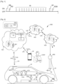
- Fig.1 shows as an example a sequence of wake-up/sleep operations of the on-board telematics module and the smart antenna during an electric charging session of the vehicle's electric battery, the "ON" and “OFF” states representing respectively the wake-up and sleep of these devices.
- a multitude of RI wake-ups occur between start RD and end RF wake-ups of the electric charging session.
- Connecting the electric charging cable to the vehicle causes a first RB wake-up of the devices.
- Disconnecting the electric charging cable from the vehicle causes a last RDB wake-up of the devices.
- the vehicle's telematics module and smart antenna are designed for a certain number of wake-ups per day, for example, one to two dozen wake-ups per day.
- a method for managing the wake-up of a computer in a vehicle connected to an electric charging station.
- characteristics of a control signal are continuously detected to define a wake-up vector.
- the computer wake-up is decided on the basis of the wake-up vector and an ordered list of different patterns of the control signal.
- DE 10 2011 107055 A1 discloses a method for estimating the state of charge of an electric battery of an electrified vehicle implemented in an electric charging system where a server and said electrified vehicle are in data communication, said method comprises, at the start of an electric charging session, a first communication of data from said electrified vehicle to said server, comprising electric charging session data including vehicle identification data, a first effective state of charge of said electric battery, a state of health of said electric battery and a charging mode.
- the invention relates to a method for estimating the state of charge of an electric battery of an electrified vehicle implemented in an electric charging system for electrified vehicles comprising electric charging means connected to an electrical power supply network and providing electrical recharging of the electric battery, at least a first computer server hosting a connected vehicle management software system and a wide area data communication network through which the electrified vehicle and the first computer server are in data communication.
- the method comprises, at the start of an electric charging session at a time t 0 , a first communication of data from the electrified vehicle to the first computer server, this first communication of data comprising electric charging session data including vehicle identification data, a first effective state of charge of the electric battery, a state of health of the electric battery and a charging mode, and, during the electric charging session, an estimation and a provision by the first computer server of an estimated state of charge, the estimated state of charge being determined from the electric charging session data, an energy capacity of the electric battery and a first estimation calculation factor, the first estimation calculation factor being determined by selection from a database of estimation calculation factors accessible to the first computer server and from the electric charging session data.
- the method comprises a determination of the first estimation calculation factor using an artificial intelligence module.
- the estimated state of charge is determined using a second mapping between state of charge and charging current, a third mapping defining a time profile of charging current, and a second calculation function giving the estimated state of charge.
- the method comprises providing the estimated load state to a second computer server. hosting an energy management software system for the electrical power supply network, the second computer server being in data communication with the first computer server through the wide area data communication network.
- the method comprises providing the estimated state of charge to a computing device of a user of the electrified vehicle, the computing device being in data communication with the first computing server through the wide area data communication network.
- the computing device is a so-called smartphone.
- the invention also relates to a computer server comprising a data storage device storing program instructions for implementing the method as briefly described above.
- the method according to the invention is described here in the context of an electric charging system for electrified vehicles based on static wired charging through a fleet of electric charging stations.
- the invention is not limited to this architecture of an electric charging system for electrified vehicles and may be implemented in other types of systems such as those based on static or dynamic induction charging.
- an electrified vehicle VE is connected to a BRE electric charging station by a CE electric cable, through a PR charging socket.
- the BRE electric charging station is connected to an RE electricity supply network and is part of a fleet managed by an electric charging service provider.
- the electrified vehicle VE is a vehicle connected by radio link to a wide area data communication network, such as the Internet, and includes in particular a high-voltage electric traction battery BAT and an on-board electric converter OBC of the alternating current/direct current type called “AC/DC”.
- High-voltage contactors CT are provided for the connection/disconnection of the electric battery with the converter OBC and the electric power circuit of the vehicle.
- the management of the electric battery BAT is ensured by an electric battery management module BMS connected to a CAN data communication network of the electrified vehicle VE.
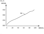
- the electric battery management module BMS is associated with current and voltage sensors (not shown) and is capable of providing data relating to the electric battery BAT, such as its state of charge "SOC" (for "State Of Charge” in English), its state of health SOH (for "State Of Health” in English) and its open circuit voltage OCV (for "Open Circuit Voltage” in English).
- SOC state of charge
- SOH for "State Of Health” in English
- OCV open Circuit Voltage
- Other on-board electronics components such as a telematics module BTA, a smart antenna BSRF, a vehicle supervisor module VSM and a vehicle control unit VCU are also visible at the Fig.2 and are connected to the CAN network.
- the NS1 server cloud hosts a SWC connected vehicle management software system, for example from the car manufacturer of the electrified vehicle EV, providing several connectivity and data processing services for a fleet of connected vehicles.
- vehicle management software system connected SWC is hosted in one or more SRC computer servers of the NS1 cloud.
- the SRC computer server includes, among other things, a processor PROC that communicates with a data storage device HD, and conventional hardware devices such as NI network interfaces and other devices (not shown).
- the processor PROC includes one or more central data processing units (not shown) and volatile and non-volatile memories (not shown) for executing computer programs.
- the SWC connected vehicle management software system comprises a MLE software module dedicated to implementing the method according to the invention for estimating the state of charge of the electric traction battery BAT.
- the method according to the invention is implemented in particular by the execution by the PROC processor of code instructions of the MLE software module.
- the electrified vehicle VE is connected to the connected vehicle management software system SWC and to the MLE software module by a data communication radio link LR1, typically through a cellular radiotelephone network in “3G”, “4G” or “5G” mode, for example.
- the user USER of the electrified vehicle VE through a dedicated software application installed on his computer device SP, such as a smartphone, communicates with a consultation service of the connected vehicle management software system SWC.
- the smartphone SP is connected to the SWC system and to the MLE software module by a data communication radio link LR2 typically through the aforementioned cellular radiotelephone network.
- the user USER has the possibility to follow the recharging of the electric battery BAT of his vehicle.
- the NS2 server cloud hosts an EMS energy management software system.
- the EMS system is responsible for managing intelligent charging of the BAT electric battery as part of a “Smart Grid” type electric power transmission network.
- the EMS system communicates with the SWC connected vehicle management software system via a LR3 data communication link.
- the NS3 server cloud hosts a UTP software system of the electric charging service provider that operates the fleet of electric charging stations of which the BRE station is part.
- the UTP electric charging service provider software system communicates with the EMS energy management software system through an LR4 data communication link.
- the detection of the connection of the CE charging electric cable causes the transmission of DSC electric charging session data to the NS1 server cloud.
- the DSC electric charging session data includes in particular a vehicle identifier / user VE/USER, a recommended MC charging mode for the vehicle, an initial state of charge SOC 0 and the state of health SOH of the electric battery BAT.
- the initial state of charge SOC 0 and the state of health SOH of the electric battery BAT are those indicated at that time by the electric battery management module BMS.
- the MC charging mode recommended for the vehicle may be retrieved from a database by the connected vehicle management software system SWC and/or the MLE software module from the vehicle/user identifier VE/USER.
- Table 1 below shows different available charging modes, namely, at constant power, with power profile P(t) or with current profile I(t).
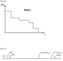
- a charging curve with power profile P(t) of the charging mode called "Mode 2" is shown as an example in Fig.3 .
- These DSC data are processed by the MLE software module, in particular by an artificial intelligence module AI associated therewith, so as to obtain an appropriate estimation calculation factor ⁇ , as will become more clearly apparent later.
- Mass data may also be used by the artificial intelligence module AI, together with the DSC data, to determine the appropriate estimation calculation factor ⁇ .
- a charging setpoint CRE which is a charging current setpoint or a charging power setpoint depending on the charging mode MC, is determined following data exchanges between the connected vehicle management software system SWC and the energy management software system EMS and is transmitted to the electrified vehicle EV.
- the charging setpoint CRE is used in particular for controlling the OBC converter and the management provided by the BMS module.
- the EMS energy management software system exchanges data with the UTP electric charging service provider software system to establish and manage the progress of the electric charging session.
- the BRE electric charging station is controlled by the UTP electric charging service provider software system.
- UTP electric charging service to recharge the BAT electric battery according to the appropriate MC charging mode.
- the invention during the course of the electric charging session, it is an estimated state of charge SOC E , determined by the software module MLE, which is provided to the energy management software system EMS for its intelligent management of the charging and to the dedicated software application hosted in the smartphone SP of the user USER each time they are requested.
- the invention thus makes it possible during the electric charging session to drastically reduce the number of wake-up/sleep operations of the on-board electronic components concerned of the electrified vehicle VE.
- Fig.4 shows, as an example, a sequence of wake-up/sleep operations of the BTA telematics module and the BSRF smart antenna occurring with the method of the invention during the electric recharging session of the BAT electric battery.
- the “ON” and “OFF” states represent respectively the waking up and the sleeping of these devices.
- a single RP1 wake-up occurs between the start RD1 and end RF1 wake-ups of the electric charging session.
- Connecting the CE electric charging cable to the EV electrified vehicle causes a first RB1 wake-up of the devices.
- Disconnecting the CE electric charging cable from the vehicle causes a final RDB1 wake-up of the devices.
- the charging instruction CRE is transmitted back to the electrified vehicle VE during the start of the electric charging session wake-up RD1.
- the single RP1 wake-up during the electric charging session corresponds to a request from the MLE software module for a reading of the actual state of charge, designated SOC R1 , of the electric battery BAT.
- the actual state of charge SOC R1 is then provided by the vehicle's BMS module and this is transmitted to the MLE software module.
- This reading requested by the MLE software module of the actual state of charge SOC R1 during the electric charging session is not systematic, but can be decided by the MLE software module for the accuracy of the estimate, so as to recalibrate the estimated state of charge SOC E to the actual state of charge SOC R1 of the electric battery BAT and thus correct in closed loop any possible drift of the SOC E estimate made by the MLE software module.
- SOC R2 Another reading of the effective state of charge, designated SOC R2 , may be requested from the BMS module by the MLE software module at the end of the electric charging session, typically during the RF1 wake-up. Like that occurring during the RP1 wake-up, this reading of the effective state of charge SOC R2 allows a closed-loop correction by the MLE software module of a possible drift in the SOC E estimate, this correction being carried out here at the end of the electric charging session.
- the method of the invention uses functional blocks B0 to B7.
- Functional block B0 represents the initial transmission of the DSC electric charging session data and the subsequent transmissions of the actual states of charge SOC R1 , SOC R2 , of the electrified vehicle EV to the NS1 server cloud and the MLE software module.
- the functional block B1 represents the storage in a database BD ⁇ of a set of estimation correction factors ⁇ .
- the estimation correction factors ⁇ in the database BD ⁇ are sorted and assigned to the different electrified vehicles VE and/or users USER managed by the connected vehicle management software system SWC.
- the database BD ⁇ is hosted in the NS1 server cloud, more precisely in the HD data storage device (cf. Fig.2 ).
- Function block B2 represents the start of an electric charging session.
- the DSC electric charging session data is then received and taken into account by the processing process of the MLE software module.
- the functional block B3 is then executed and determines an appropriate estimation calculation factor ⁇ S for the considered electric charging session.
- the appropriate estimation calculation factor ⁇ S is determined based on the electric charging session data DSC which define a particular profile for the electric charging session.
- the aforementioned artificial intelligence module AI may be used to select the appropriate estimation calculation factor ⁇ S in the database BD ⁇ from the profile deduced from the DSC data.
- Other methods may be used, while remaining within the scope of the invention, to determine the appropriate estimation calculation factor ⁇ S , such as interpolation methods, similarity selection and others.
- Function block B4 is the real-time calculation of the estimated state of charge SOC E (t).
- the calculation of the estimated state of charge SOC E (t) is carried out differently depending on the charging setpoint CRE which is available and which depends on the charging mode MC.
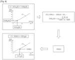
- Fig.6 illustrates the calculation of the estimated state of charge SOC E (t) in the case where the charging instruction CRE is a constant power electric charging instruction PC.
- the state of charge SOC E (t) is estimated using a C1 mapping and a calculation function F1 visible in the Fig.6 .
- the C1 map represented by a curve, gives the energy state SOE (in kWh) of the electric battery BAT as a function of its state of charge SOC (in %).
- the SOE 0 energy state is first determined using the C1 map from the available SOC 0 state of charge. Interpolation from values close to the C1 map is used if necessary to obtain the SOE 0 energy state with good accuracy.
- the estimated state of charge SOC E (t) is determined using the C1 mapping from the SOE(t) state obtained with the F1 function. An interpolation from values close to the C1 mapping is used if necessary to obtain the estimated state of charge SOC E (t) with good accuracy.
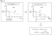
- Fig.7 illustrates the calculation of the estimated state of charge SOC E (t) in the case where the charging instruction CRE is an electric charging instruction with current profile I(t), for example at a power of 7 kW.
- the state of charge SOC E (t) is estimated using maps C2, C3 and a calculation function F2 visible in the Fig.7 .
- the C2 map represented by a curve, gives the recharge current I (in A) as a function of the state of charge SOC (in %).
- the C3 map represented by a curve, gives the current profile I(t) over time for recharging the electric battery BAT.
- An initial current I0, at the start of charging, is determined using the C2 mapping from the available state of charge SOC 0.
- An interpolation from values close to the C2 mapping is used if necessary to obtain the initial current I0 with good precision.
- the integral of the curve I(t) of the mapping C3 between a time t0, corresponding to the initial current I0, and the time t considered is necessary for the calculation of the function F2.
- the surface S in the curve I(t) represents the value of this integral. Interpolations from values close to the mapping C3 are used if necessary to obtain the surface S with good accuracy.
- the estimated state of charge SOC E (t) is given by the function F2.
- Functional blocks B5 and B6 concern the correction during the electric charging session, mentioned above with reference to the Fig.4 (cf. RP1). This intermediate correction is decided by the functional block B5, for example beyond a certain duration of the electric charging session. It gives rise to a reading of the state of charge SOC R1 of the electric battery BAT which occurs at a time t R1 (cf. Fig.8 ).
- Functional block B7 concerns a final correction at the end of the electric charging session, mentioned above with reference to the Fig.4 (cf. RF1). It is systematic and gives rise to a reading of the state of charge SOC R2 of the electric battery BAT which occurs at a time t R2 (cf. Fig.8 ).
- a calculation function F3 shown in the Fig.8 is used to correct the value of the estimation calculation factor ⁇ and match it to the actual states of charge SOC R1 and SOC R2 which are read at times t R1 and t R2 , respectively.
- the estimation calculation factor ⁇ R1 is calculated from the value of SOC E with the factor ⁇ S (see B3) and SOC R1 .
- the factor ⁇ R1 is used by the functional block B4 for the rest of the calculation of the estimated state of charge SOC E (t).
- the factor ⁇ R1 is transmitted to the functional block B1 to enrich the database BD ⁇ .
- the estimation calculation factor ⁇ R2 is calculated from the value of SOC E with the factor ⁇ R1 (or ⁇ S if the intermediate correction above has not been performed) and SOC R2 .
- the factor ⁇ R2 is transmitted to the functional block B1 to enrich the database BD ⁇ .
Landscapes
- Engineering & Computer Science (AREA)
- Power Engineering (AREA)
- Mechanical Engineering (AREA)
- Transportation (AREA)
- Sustainable Energy (AREA)
- Life Sciences & Earth Sciences (AREA)
- Sustainable Development (AREA)
- Manufacturing & Machinery (AREA)
- Chemical & Material Sciences (AREA)
- Chemical Kinetics & Catalysis (AREA)
- Electrochemistry (AREA)
- General Chemical & Material Sciences (AREA)
- Physics & Mathematics (AREA)
- General Physics & Mathematics (AREA)
- Charge And Discharge Circuits For Batteries Or The Like (AREA)
Claims (10)
- Verfahren zur Schätzung des Ladezustands einer elektrischen Batterie (BAT) eines elektrifizierten Fahrzeugs (EV), implementiert in einem elektrischen Ladesystem für elektrifizierte Fahrzeuge (SRE), umfassend elektrische Lademittel (BRE), die an ein elektrisches Versorgungsnetz (RE) angeschlossen sind und Sicherstellen der elektrischen Wiederaufladung der elektrischen Batterie (BAT), mindestens einen ersten Computerserver (NS1, SRC), der ein Softwaresystem (SWC) für das verbundene Fahrzeugmanagement und einen Netzwerkdatenkommunikationsbereich hostet, über den das elektrifizierte Fahrzeug (EV) und der erste Computer kommunizieren Server (NS1, SRC) befinden sich in der Datenkommunikation (LR1) und wo das Verfahren umfasst zu Beginn einer elektrischen Ladesitzung zu einem Zeitpunkt t ∘ eine erste Datenkommunikation von dem elektrifizierten Fahrzeug (EV) an den ersten Computerserver (NS1, SRC), wobei die erste Datenkommunikation Daten von der elektrischen Ladesitzung umfasst (DSC) einschließlich Fahrzeugidentifikationsdaten (VE/USER), eines ersten effektiven Ladezustands (S0 C 0 ) der elektrischen Batterie (BAT), eines Gesundheitszustands (SOH) der elektrischen Batterie (BAT) und eines Ladevorgangs Modus (MC); und dadurch gekennzeichnet, dass:
während der elektrischen Ladesitzung eine Schätzung und a Bereitstellung eines Ladezustands durch den ersten Computerserver (NS1, SRC). geschätzt (SOCE ), wobei der geschätzte Ladezustand (SOCE) aus den Daten der elektrischen Ladesitzung (DSC), einer Energiekapazität (C, E) der elektrischen Batterie (BAT) und einem ersten Schätzberechnungsfaktor ( αs) bestimmt wird. , wobei der erste Schätzberechnungsfaktor ( αs) durch Auswahl aus einer Datenbank von Schätzberechnungsfaktoren (DB α), auf die der erste Computerserver (NS1, SRC) zugreifen kann, und aus den Daten der elektrischen Ladesitzung (DSC) bestimmt wird. - Verfahren nach Anspruch 1, dadurch gekennzeichnet, dass es eine Bestimmung des ersten Schätzberechnungsfaktors ( αs) unter Verwendung von a umfasst Modul Künstliche Intelligenz (KI).
- Verfahren nach Anspruch 1 oder 2, dadurch gekennzeichnet, dass es während des elektrischen Ladevorgangs eine zweite Datenübertragung von dem elektrifizierten Fahrzeug (EV) an den ersten Computerserver (NS1, SRC) zu einem Zeitpunkt tRi umfasst zweite Datenkommunikation, die einen zweiten effektiven Ladezustand (SOCR1 ) der elektrischen Batterie (BAT) und eine Zwischenkorrektur des geschätzten Ladezustands (SOCE ) aus dem zweiten effektiven Ladezustand (SOCR1 ) und eine Bestimmung umfasst durch Berechnung eines zweiten Schätzberechnungsfaktors ( αR1) aus dem zweiten effektiven Ladezustand (SOCR1 ) gemäß einer Funktion von Berechnung (F3) folgende:

- Verfahren nach einem der Ansprüche 1 bis 3, dadurch gekennzeichnet, dass es am Ende des elektrischen Aufladevorgangs zu einem Zeitpunkt t R2 eine weitere Datenübertragung von dem elektrifizierten Fahrzeug (EV) an den ersten Servercomputer (NS1, SRC), wobei die andere Datenkommunikation einen dritten effektiven Ladezustand (SOCR2 ) der elektrischen Batterie (BAT) und eine abschließende Korrektur des geschätzten Ladezustands (SOCE) aus dem dritten effektiven Ladezustand (SOCR2), eine Bestimmung durch Berechnung eines dritten Schätzberechnungsfaktors (αR2) aus dem zweiten effektiven Ladezustand (SOCR1 ) gemäß einer Funktion von Berechnung (F3) :

- Verfahren nach einem der Ansprüche 1 bis 4, wobei der Lademodus (MC) einen elektrischen Ladesollwert (PC) mit konstanter Leistung umfasst, dadurch gekennzeichnet, dass der geschätzte Ladezustand (SOCE ) mit Hilfe von bestimmt wird:- eine erste Karte (C1), die einen Energiezustand als Funktion eines Ladezustands der elektrischen Batterie (BAT) angibt und umgekehrt,- und eine erste Berechnungsfunktion (F1), die einen geschätzten Energiezustand (SOE) liefert, wobei diese Berechnungsfunktion (F1) wie folgt lautet:Oder:
 - PC und SOH stellen den Ladesollwert bei konstanter Leistung und den Gesundheitszustand der BAT-Elektrobatterie dar.- - E stellt die Nennenergiekapazität der BAT-Elektrobatterie in kWh dar und die Zahl 3600 wandelt zwischen der Zeiteinheit um " Stunde " der Kapazität E und die Zeiteinheit "Sekunde" der Zeitvariablen t.- αE ist der Schätzberechnungsfaktor, dessen Wert zunächst dem von entspricht erster Schätzungsberechnungsfaktor αs,dieser geschätzte Energiezustand (SOE), aus dem dieser Energiezustand bestimmt wird geschätzte Last (SOC E ) über die erste Abbildung (C1).
 - Verfahren nach einem der Ansprüche 1 bis 4, wobei der Lademodus einen elektrischen Ladesollwert mit Stromverlauf (I(t)) umfasst,
gekennzeichnet , dass der geschätzte Ladezustand (SOCE) unter Verwendung einer zweiten Abbildung zwischen Ladezustand und Wiederaufladestrom (C2), einer dritten Abbildung (C3), die ein zeitliches Aufladestromprofil (I(t)) definiert, und a zweite Berechnungsfunktion (F2), die den geschätzten Ladezustand (SOCE) angibt. - Verfahren nach einem der Ansprüche 1 bis 6, dadurch gekennzeichnet, dass es eine Lieferung des geschätzten Ladezustands (SOC E ) an einen zweiten Computerserver (NS2) umfasst, der ein Energiemanagement-Softwaresystem (EMS) der Netzwerkstromversorgung hostet (RE), wobei der zweite Computerserver (NS2)
über das erweiterte Datenkommunikationsnetzwerk in Datenkommunikation mit dem ersten Computerserver (NS1, SRC) steht. - Verfahren nach einem der Ansprüche 1 bis 7, dadurch gekennzeichnet, dass es die Bereitstellung des geschätzten Ladezustands (SOC E ) an ein Gerät umfasst Computergerät (SP) eines Benutzers (USER) des elektrifizierten Fahrzeugs (EV), wobei das Computergerät (SP) über das erweiterte Datenkommunikationsnetzwerk in Datenkommunikation mit dem ersten Computerserver (NS1, SRC) steht.
- Verfahren nach Anspruch 8, dadurch gekennzeichnet, dass die Vorrichtung Computer ist ein Smartphone, das Smartphone (SP) genannt wird.
- Computerserver (NS1, SRC), der ein Datenspeichergerät (HD) umfasst, das Programmanweisungen (MLE) zur Implementierung des Verfahrens nach einem der Ansprüche 1 bis 9 speichert.
Applications Claiming Priority (2)
| Application Number | Priority Date | Filing Date | Title |
|---|---|---|---|
| FR2005535A FR3110881A1 (fr) | 2020-05-26 | 2020-05-26 | Procédé d’estimation de l’état de charge d’une batterie électrique notamment pour la gestion énergétique de recharge des véhicules électrifiés |
| PCT/FR2021/050526 WO2021240075A1 (fr) | 2020-05-26 | 2021-03-25 | Procédé d'estimation de l'état de charge d'une batterie électrique notamment pour la gestion énergétique de recharge des véhicules électrifiés |
Publications (2)
| Publication Number | Publication Date |
|---|---|
| EP4157665A1 EP4157665A1 (de) | 2023-04-05 |
| EP4157665B1 true EP4157665B1 (de) | 2025-01-15 |
Family
ID=74045450
Family Applications (1)
| Application Number | Title | Priority Date | Filing Date |
|---|---|---|---|
| EP21732378.1A Active EP4157665B1 (de) | 2020-05-26 | 2021-03-25 | Verfahren zur abschätzung des ladezustands einer batterie insbesondere zur wiederaufladensverwaltung von elektrofahrzeugen |
Country Status (3)
| Country | Link |
|---|---|
| EP (1) | EP4157665B1 (de) |
| FR (1) | FR3110881A1 (de) |
| WO (1) | WO2021240075A1 (de) |
Families Citing this family (1)
| Publication number | Priority date | Publication date | Assignee | Title |
|---|---|---|---|---|
| CN116714476B (zh) * | 2023-05-26 | 2025-07-22 | 深蓝汽车科技有限公司 | 一种电池数据处理方法、装置、电子设备及存储介质 |
Family Cites Families (8)
| Publication number | Priority date | Publication date | Assignee | Title |
|---|---|---|---|---|
| NL6905027A (de) | 1968-04-04 | 1969-10-07 | ||
| CN103392133A (zh) * | 2011-03-07 | 2013-11-13 | 株式会社日立制作所 | 电池状态推定方法和电池管理系统 |
| DE102011107055A1 (de) * | 2011-05-01 | 2012-11-08 | Still Gmbh | Verfahren zur Steuerung des Lade-/Entladebetriebs einer Traktionsbatterie |
| KR102105808B1 (ko) * | 2013-03-15 | 2020-04-29 | 크라운 이큅먼트 코포레이션 | 배터리 상태 측정 기준들에 대한 부분적인 소모 추정 |
| FR3041782B1 (fr) | 2015-09-28 | 2018-01-26 | Continental Automotive France | Procede de reveil d'un calculateur, notamment pour un systeme de charge de batterie de vehicule hybride |
| US10300807B2 (en) * | 2016-02-04 | 2019-05-28 | Johnson Controls Technology Company | Systems and methods for state of charge and capacity estimation of a rechargeable battery |
| US10160340B2 (en) * | 2016-03-16 | 2018-12-25 | GM Global Technology Operations LLC | Adaptive system and method for optimizing battery life in a plug-in vehicle |
| EP3587171A1 (de) * | 2018-06-28 | 2020-01-01 | Kwang Yang Motor Co., Ltd. | Verfahren zur informationsbereitstellung und elektrisches trägersystem |
-
2020
- 2020-05-26 FR FR2005535A patent/FR3110881A1/fr not_active Withdrawn
-
2021
- 2021-03-25 EP EP21732378.1A patent/EP4157665B1/de active Active
- 2021-03-25 WO PCT/FR2021/050526 patent/WO2021240075A1/fr not_active Ceased
Also Published As
| Publication number | Publication date |
|---|---|
| EP4157665A1 (de) | 2023-04-05 |
| WO2021240075A1 (fr) | 2021-12-02 |
| FR3110881A1 (fr) | 2021-12-03 |
Similar Documents
| Publication | Publication Date | Title |
|---|---|---|
| US11904717B2 (en) | Intelligent preconditioning for high voltage electric vehicle batteries | |
| WO2020114795A1 (fr) | Procédé de gestion optimisée de la charge d'une flotte de véhicules électriques | |
| US10752128B1 (en) | Systems and method for EV battery second-life management | |
| CN115632422A (zh) | 电力供求调整方法以及电力供求管理装置 | |
| CN116176560B (zh) | 增程车辆的功率分配方法、装置及相关设备 | |
| FR3122951A1 (fr) | Procédé et système de contrôle de la recharge d’une flotte de véhicules automobiles électriques | |
| EP4288304B1 (de) | Verfahren zur schätzung eines ladezustands einer batterie eines elektrofahrzeugs für fernüberwachungssystem | |
| EP2710704A2 (de) | System und verfahren zur schätzung des endes des ladevorganges einer batterie | |
| WO2021148726A1 (fr) | Procédé et dispositif de contrôle d'un système de stockage d'énergie, par exemple une batterie de véhicule | |
| EP4157665B1 (de) | Verfahren zur abschätzung des ladezustands einer batterie insbesondere zur wiederaufladensverwaltung von elektrofahrzeugen | |
| EP4002634A1 (de) | Leistungsoptimierte steuerung einer batterie, die an der primären frequenzregelung beteiligt ist | |
| WO2010097554A1 (fr) | Dispositif et procédé de gestion optimisée de l'énergie électrique d'une source de stockage électrochimique embarquée dans un véhicule hybride | |
| EP2928721B1 (de) | Verfahren zur verteilten verwaltung des ladevorgangs von traktionsbatterien von elektrofahrzeugen | |
| EP2686932A2 (de) | Zentralisierte verwaltung der stromversorgung mehrerer örtlicher versorgungsnetze | |
| CN117783731B (zh) | 商用车供用电系统健康状态监测方法、装置及终端 | |
| WO2023025995A1 (fr) | Procede de gestion d'une session de recharge d'un vehicule electrifie pour determiner un etat de charge cible en fin de charge | |
| EP3435103B1 (de) | Schätzungsmethode des energiezustands einer batterie | |
| CN115042654B (zh) | 充电站的排位充电方法及装置、存储介质、终端 | |
| CN120773615A (zh) | 加热温度确定方法、装置、设备、存储介质及车辆 | |
| FR3161495A1 (fr) | Obtention d’informations relatives à des caractéristiques d’une borne de recharge | |
| CN116599090B (zh) | 基于储能资源的功率调节方法、装置和计算机可读介质 | |
| CN117565758B (zh) | 混合动力汽车的功率管理方法及装置 | |
| JP2021077123A (ja) | 提示システム、提示方法、及びプログラム | |
| FR2974950A1 (fr) | Dispositif et procede de determination des tensions pouvant etre appliquees a un reseau electrique pour la gestion de differentes contraintes de tension specifiques. | |
| EP4648250A1 (de) | Batterieentladungssystem |
Legal Events
| Date | Code | Title | Description |
|---|---|---|---|
| STAA | Information on the status of an ep patent application or granted ep patent |
Free format text: STATUS: UNKNOWN |
|
| STAA | Information on the status of an ep patent application or granted ep patent |
Free format text: STATUS: THE INTERNATIONAL PUBLICATION HAS BEEN MADE |
|
| PUAI | Public reference made under article 153(3) epc to a published international application that has entered the european phase |
Free format text: ORIGINAL CODE: 0009012 |
|
| STAA | Information on the status of an ep patent application or granted ep patent |
Free format text: STATUS: REQUEST FOR EXAMINATION WAS MADE |
|
| 17P | Request for examination filed |
Effective date: 20221005 |
|
| AK | Designated contracting states |
Kind code of ref document: A1 Designated state(s): AL AT BE BG CH CY CZ DE DK EE ES FI FR GB GR HR HU IE IS IT LI LT LU LV MC MK MT NL NO PL PT RO RS SE SI SK SM TR |
|
| DAV | Request for validation of the european patent (deleted) | ||
| DAX | Request for extension of the european patent (deleted) | ||
| RAP3 | Party data changed (applicant data changed or rights of an application transferred) |
Owner name: STELLANTIS AUTO SAS |
|
| STAA | Information on the status of an ep patent application or granted ep patent |
Free format text: STATUS: EXAMINATION IS IN PROGRESS |
|
| 17Q | First examination report despatched |
Effective date: 20240430 |
|
| GRAP | Despatch of communication of intention to grant a patent |
Free format text: ORIGINAL CODE: EPIDOSNIGR1 |
|
| STAA | Information on the status of an ep patent application or granted ep patent |
Free format text: STATUS: GRANT OF PATENT IS INTENDED |
|
| RIC1 | Information provided on ipc code assigned before grant |
Ipc: G01R 31/382 20190101ALI20240903BHEP Ipc: G01R 31/392 20190101ALI20240903BHEP Ipc: G01R 31/387 20190101ALI20240903BHEP Ipc: G01R 31/367 20190101ALI20240903BHEP Ipc: B60L 58/16 20190101ALI20240903BHEP Ipc: H01M 10/44 20060101ALI20240903BHEP Ipc: B60L 58/12 20190101ALI20240903BHEP Ipc: B60L 53/65 20190101ALI20240903BHEP Ipc: H01M 10/48 20060101ALI20240903BHEP Ipc: B60L 3/12 20060101AFI20240903BHEP |
|
| INTG | Intention to grant announced |
Effective date: 20240920 |
|
| GRAS | Grant fee paid |
Free format text: ORIGINAL CODE: EPIDOSNIGR3 |
|
| GRAA | (expected) grant |
Free format text: ORIGINAL CODE: 0009210 |
|
| STAA | Information on the status of an ep patent application or granted ep patent |
Free format text: STATUS: THE PATENT HAS BEEN GRANTED |
|
| AK | Designated contracting states |
Kind code of ref document: B1 Designated state(s): AL AT BE BG CH CY CZ DE DK EE ES FI FR GB GR HR HU IE IS IT LI LT LU LV MC MK MT NL NO PL PT RO RS SE SI SK SM TR |
|
| REG | Reference to a national code |
Ref country code: CH Ref legal event code: EP Ref country code: GB Ref legal event code: FG4D Free format text: NOT ENGLISH |
|
| REG | Reference to a national code |
Ref country code: DE Ref legal event code: R096 Ref document number: 602021024982 Country of ref document: DE |
|
| REG | Reference to a national code |
Ref country code: IE Ref legal event code: FG4D Free format text: LANGUAGE OF EP DOCUMENT: FRENCH |
|
| REG | Reference to a national code |
Ref country code: DE Ref legal event code: R084 Ref document number: 602021024982 Country of ref document: DE |
|
| PGFP | Annual fee paid to national office [announced via postgrant information from national office to epo] |
Ref country code: AT Payment date: 20250417 Year of fee payment: 5 |
|
| REG | Reference to a national code |
Ref country code: NL Ref legal event code: MP Effective date: 20250115 |
|
| PG25 | Lapsed in a contracting state [announced via postgrant information from national office to epo] |
Ref country code: NL Free format text: LAPSE BECAUSE OF FAILURE TO SUBMIT A TRANSLATION OF THE DESCRIPTION OR TO PAY THE FEE WITHIN THE PRESCRIBED TIME-LIMIT Effective date: 20250115 |
|
| PG25 | Lapsed in a contracting state [announced via postgrant information from national office to epo] |
Ref country code: RS Free format text: LAPSE BECAUSE OF FAILURE TO SUBMIT A TRANSLATION OF THE DESCRIPTION OR TO PAY THE FEE WITHIN THE PRESCRIBED TIME-LIMIT Effective date: 20250415 |
|
| PG25 | Lapsed in a contracting state [announced via postgrant information from national office to epo] |
Ref country code: FI Free format text: LAPSE BECAUSE OF FAILURE TO SUBMIT A TRANSLATION OF THE DESCRIPTION OR TO PAY THE FEE WITHIN THE PRESCRIBED TIME-LIMIT Effective date: 20250115 |
|
| PG25 | Lapsed in a contracting state [announced via postgrant information from national office to epo] |
Ref country code: PL Free format text: LAPSE BECAUSE OF FAILURE TO SUBMIT A TRANSLATION OF THE DESCRIPTION OR TO PAY THE FEE WITHIN THE PRESCRIBED TIME-LIMIT Effective date: 20250115 |
|
| PG25 | Lapsed in a contracting state [announced via postgrant information from national office to epo] |
Ref country code: ES Free format text: LAPSE BECAUSE OF FAILURE TO SUBMIT A TRANSLATION OF THE DESCRIPTION OR TO PAY THE FEE WITHIN THE PRESCRIBED TIME-LIMIT Effective date: 20250115 |
|
| REG | Reference to a national code |
Ref country code: LT Ref legal event code: MG9D |
|
| PG25 | Lapsed in a contracting state [announced via postgrant information from national office to epo] |
Ref country code: NO Free format text: LAPSE BECAUSE OF FAILURE TO SUBMIT A TRANSLATION OF THE DESCRIPTION OR TO PAY THE FEE WITHIN THE PRESCRIBED TIME-LIMIT Effective date: 20250415 Ref country code: IS Free format text: LAPSE BECAUSE OF FAILURE TO SUBMIT A TRANSLATION OF THE DESCRIPTION OR TO PAY THE FEE WITHIN THE PRESCRIBED TIME-LIMIT Effective date: 20250515 |
|
| REG | Reference to a national code |
Ref country code: AT Ref legal event code: MK05 Ref document number: 1759659 Country of ref document: AT Kind code of ref document: T Effective date: 20250115 |
|
| PG25 | Lapsed in a contracting state [announced via postgrant information from national office to epo] |
Ref country code: HR Free format text: LAPSE BECAUSE OF FAILURE TO SUBMIT A TRANSLATION OF THE DESCRIPTION OR TO PAY THE FEE WITHIN THE PRESCRIBED TIME-LIMIT Effective date: 20250115 |
|
| PG25 | Lapsed in a contracting state [announced via postgrant information from national office to epo] |
Ref country code: LV Free format text: LAPSE BECAUSE OF FAILURE TO SUBMIT A TRANSLATION OF THE DESCRIPTION OR TO PAY THE FEE WITHIN THE PRESCRIBED TIME-LIMIT Effective date: 20250115 Ref country code: PT Free format text: LAPSE BECAUSE OF FAILURE TO SUBMIT A TRANSLATION OF THE DESCRIPTION OR TO PAY THE FEE WITHIN THE PRESCRIBED TIME-LIMIT Effective date: 20250515 |
|
| PG25 | Lapsed in a contracting state [announced via postgrant information from national office to epo] |
Ref country code: BG Free format text: LAPSE BECAUSE OF FAILURE TO SUBMIT A TRANSLATION OF THE DESCRIPTION OR TO PAY THE FEE WITHIN THE PRESCRIBED TIME-LIMIT Effective date: 20250115 Ref country code: GR Free format text: LAPSE BECAUSE OF FAILURE TO SUBMIT A TRANSLATION OF THE DESCRIPTION OR TO PAY THE FEE WITHIN THE PRESCRIBED TIME-LIMIT Effective date: 20250416 |
|
| PG25 | Lapsed in a contracting state [announced via postgrant information from national office to epo] |
Ref country code: AT Free format text: LAPSE BECAUSE OF FAILURE TO SUBMIT A TRANSLATION OF THE DESCRIPTION OR TO PAY THE FEE WITHIN THE PRESCRIBED TIME-LIMIT Effective date: 20250115 |
|
| PG25 | Lapsed in a contracting state [announced via postgrant information from national office to epo] |
Ref country code: SE Free format text: LAPSE BECAUSE OF FAILURE TO SUBMIT A TRANSLATION OF THE DESCRIPTION OR TO PAY THE FEE WITHIN THE PRESCRIBED TIME-LIMIT Effective date: 20250115 |
|
| PG25 | Lapsed in a contracting state [announced via postgrant information from national office to epo] |
Ref country code: SM Free format text: LAPSE BECAUSE OF FAILURE TO SUBMIT A TRANSLATION OF THE DESCRIPTION OR TO PAY THE FEE WITHIN THE PRESCRIBED TIME-LIMIT Effective date: 20250115 |
|
| PG25 | Lapsed in a contracting state [announced via postgrant information from national office to epo] |
Ref country code: DK Free format text: LAPSE BECAUSE OF FAILURE TO SUBMIT A TRANSLATION OF THE DESCRIPTION OR TO PAY THE FEE WITHIN THE PRESCRIBED TIME-LIMIT Effective date: 20250115 |
|
| PG25 | Lapsed in a contracting state [announced via postgrant information from national office to epo] |
Ref country code: MC Free format text: LAPSE BECAUSE OF FAILURE TO SUBMIT A TRANSLATION OF THE DESCRIPTION OR TO PAY THE FEE WITHIN THE PRESCRIBED TIME-LIMIT Effective date: 20250115 |
|
| PG25 | Lapsed in a contracting state [announced via postgrant information from national office to epo] |
Ref country code: IT Free format text: LAPSE BECAUSE OF FAILURE TO SUBMIT A TRANSLATION OF THE DESCRIPTION OR TO PAY THE FEE WITHIN THE PRESCRIBED TIME-LIMIT Effective date: 20250115 |
|
| REG | Reference to a national code |
Ref country code: DE Ref legal event code: R097 Ref document number: 602021024982 Country of ref document: DE |
|
| PG25 | Lapsed in a contracting state [announced via postgrant information from national office to epo] |
Ref country code: EE Free format text: LAPSE BECAUSE OF FAILURE TO SUBMIT A TRANSLATION OF THE DESCRIPTION OR TO PAY THE FEE WITHIN THE PRESCRIBED TIME-LIMIT Effective date: 20250115 Ref country code: CZ Free format text: LAPSE BECAUSE OF FAILURE TO SUBMIT A TRANSLATION OF THE DESCRIPTION OR TO PAY THE FEE WITHIN THE PRESCRIBED TIME-LIMIT Effective date: 20250115 |
|
| REG | Reference to a national code |
Ref country code: CH Ref legal event code: H13 Free format text: ST27 STATUS EVENT CODE: U-0-0-H10-H13 (AS PROVIDED BY THE NATIONAL OFFICE) Effective date: 20251023 |
|
| PG25 | Lapsed in a contracting state [announced via postgrant information from national office to epo] |
Ref country code: RO Free format text: LAPSE BECAUSE OF FAILURE TO SUBMIT A TRANSLATION OF THE DESCRIPTION OR TO PAY THE FEE WITHIN THE PRESCRIBED TIME-LIMIT Effective date: 20250115 |
|
| PG25 | Lapsed in a contracting state [announced via postgrant information from national office to epo] |
Ref country code: SK Free format text: LAPSE BECAUSE OF FAILURE TO SUBMIT A TRANSLATION OF THE DESCRIPTION OR TO PAY THE FEE WITHIN THE PRESCRIBED TIME-LIMIT Effective date: 20250115 |
|
| PG25 | Lapsed in a contracting state [announced via postgrant information from national office to epo] |
Ref country code: LU Free format text: LAPSE BECAUSE OF NON-PAYMENT OF DUE FEES Effective date: 20250325 |
|
| PLBE | No opposition filed within time limit |
Free format text: ORIGINAL CODE: 0009261 |
|
| STAA | Information on the status of an ep patent application or granted ep patent |
Free format text: STATUS: NO OPPOSITION FILED WITHIN TIME LIMIT |
|
| REG | Reference to a national code |
Ref country code: BE Ref legal event code: MM Effective date: 20250331 |
|
| 26N | No opposition filed |
Effective date: 20251016 |
|
| GBPC | Gb: european patent ceased through non-payment of renewal fee |
Effective date: 20250415 |
|
| PG25 | Lapsed in a contracting state [announced via postgrant information from national office to epo] |
Ref country code: GB Free format text: LAPSE BECAUSE OF NON-PAYMENT OF DUE FEES Effective date: 20250415 |
|
| PG25 | Lapsed in a contracting state [announced via postgrant information from national office to epo] |
Ref country code: BE Free format text: LAPSE BECAUSE OF NON-PAYMENT OF DUE FEES Effective date: 20250331 |
|
| PG25 | Lapsed in a contracting state [announced via postgrant information from national office to epo] |
Ref country code: CH Free format text: LAPSE BECAUSE OF NON-PAYMENT OF DUE FEES Effective date: 20250331 |
|
| PG25 | Lapsed in a contracting state [announced via postgrant information from national office to epo] |
Ref country code: IE Free format text: LAPSE BECAUSE OF NON-PAYMENT OF DUE FEES Effective date: 20250325 |
|
| PGFP | Annual fee paid to national office [announced via postgrant information from national office to epo] |
Ref country code: DE Payment date: 20260219 Year of fee payment: 6 |
|
| PGFP | Annual fee paid to national office [announced via postgrant information from national office to epo] |
Ref country code: FR Payment date: 20260219 Year of fee payment: 6 |