EP4157677B1 - Implantation d'un haut-parleur et/ou d'un système d'appel d'urgence automatique dans la planche de bord d'un véhicule automobile - Google Patents
Implantation d'un haut-parleur et/ou d'un système d'appel d'urgence automatique dans la planche de bord d'un véhicule automobile Download PDFInfo
- Publication number
- EP4157677B1 EP4157677B1 EP21732396.3A EP21732396A EP4157677B1 EP 4157677 B1 EP4157677 B1 EP 4157677B1 EP 21732396 A EP21732396 A EP 21732396A EP 4157677 B1 EP4157677 B1 EP 4157677B1
- Authority
- EP
- European Patent Office
- Prior art keywords
- loudspeaker
- fixing
- bowl
- support
- dashboard
- Prior art date
- Legal status (The legal status is an assumption and is not a legal conclusion. Google has not performed a legal analysis and makes no representation as to the accuracy of the status listed.)
- Active
Links
Images


Classifications
-
- B—PERFORMING OPERATIONS; TRANSPORTING
- B60—VEHICLES IN GENERAL
- B60K—ARRANGEMENT OR MOUNTING OF PROPULSION UNITS OR OF TRANSMISSIONS IN VEHICLES; ARRANGEMENT OR MOUNTING OF PLURAL DIVERSE PRIME-MOVERS IN VEHICLES; AUXILIARY DRIVES FOR VEHICLES; INSTRUMENTATION OR DASHBOARDS FOR VEHICLES; ARRANGEMENTS IN CONNECTION WITH COOLING, AIR INTAKE, GAS EXHAUST OR FUEL SUPPLY OF PROPULSION UNITS IN VEHICLES
- B60K37/00—Dashboards
- B60K37/10—Arrangements for attaching the dashboard to the vehicle
-
- B—PERFORMING OPERATIONS; TRANSPORTING
- B60—VEHICLES IN GENERAL
- B60R—VEHICLES, VEHICLE FITTINGS, OR VEHICLE PARTS, NOT OTHERWISE PROVIDED FOR
- B60R11/00—Arrangements for holding or mounting articles, not otherwise provided for
- B60R11/02—Arrangements for holding or mounting articles, not otherwise provided for for radio sets, television sets, telephones, or the like; Arrangement of controls thereof
- B60R11/0217—Arrangements for holding or mounting articles, not otherwise provided for for radio sets, television sets, telephones, or the like; Arrangement of controls thereof for loud-speakers
-
- B—PERFORMING OPERATIONS; TRANSPORTING
- B60—VEHICLES IN GENERAL
- B60H—ARRANGEMENTS OF HEATING, COOLING, VENTILATING OR OTHER AIR-TREATING DEVICES SPECIALLY ADAPTED FOR PASSENGER OR GOODS SPACES OF VEHICLES
- B60H1/00—Heating, cooling or ventilating devices
- B60H1/00507—Details, e.g. mounting arrangements, desaeration devices
- B60H1/00514—Details of air conditioning housings
- B60H1/0055—Details of air conditioning housings the housing or parts thereof being integrated in other devices, e.g. dashboard
-
- B—PERFORMING OPERATIONS; TRANSPORTING
- B60—VEHICLES IN GENERAL
- B60H—ARRANGEMENTS OF HEATING, COOLING, VENTILATING OR OTHER AIR-TREATING DEVICES SPECIALLY ADAPTED FOR PASSENGER OR GOODS SPACES OF VEHICLES
- B60H1/00—Heating, cooling or ventilating devices
- B60H1/00507—Details, e.g. mounting arrangements, desaeration devices
- B60H1/00557—Details of ducts or cables
- B60H1/00564—Details of ducts or cables of air ducts
-
- B—PERFORMING OPERATIONS; TRANSPORTING
- B60—VEHICLES IN GENERAL
- B60K—ARRANGEMENT OR MOUNTING OF PROPULSION UNITS OR OF TRANSMISSIONS IN VEHICLES; ARRANGEMENT OR MOUNTING OF PLURAL DIVERSE PRIME-MOVERS IN VEHICLES; AUXILIARY DRIVES FOR VEHICLES; INSTRUMENTATION OR DASHBOARDS FOR VEHICLES; ARRANGEMENTS IN CONNECTION WITH COOLING, AIR INTAKE, GAS EXHAUST OR FUEL SUPPLY OF PROPULSION UNITS IN VEHICLES
- B60K35/00—Instruments specially adapted for vehicles; Arrangement of instruments in or on vehicles
- B60K35/20—Output arrangements, i.e. from vehicle to user, associated with vehicle functions or specially adapted therefor
-
- B—PERFORMING OPERATIONS; TRANSPORTING
- B60—VEHICLES IN GENERAL
- B60K—ARRANGEMENT OR MOUNTING OF PROPULSION UNITS OR OF TRANSMISSIONS IN VEHICLES; ARRANGEMENT OR MOUNTING OF PLURAL DIVERSE PRIME-MOVERS IN VEHICLES; AUXILIARY DRIVES FOR VEHICLES; INSTRUMENTATION OR DASHBOARDS FOR VEHICLES; ARRANGEMENTS IN CONNECTION WITH COOLING, AIR INTAKE, GAS EXHAUST OR FUEL SUPPLY OF PROPULSION UNITS IN VEHICLES
- B60K35/00—Instruments specially adapted for vehicles; Arrangement of instruments in or on vehicles
- B60K35/20—Output arrangements, i.e. from vehicle to user, associated with vehicle functions or specially adapted therefor
- B60K35/26—Output arrangements, i.e. from vehicle to user, associated with vehicle functions or specially adapted therefor using acoustic output
-
- B—PERFORMING OPERATIONS; TRANSPORTING
- B60—VEHICLES IN GENERAL
- B60K—ARRANGEMENT OR MOUNTING OF PROPULSION UNITS OR OF TRANSMISSIONS IN VEHICLES; ARRANGEMENT OR MOUNTING OF PLURAL DIVERSE PRIME-MOVERS IN VEHICLES; AUXILIARY DRIVES FOR VEHICLES; INSTRUMENTATION OR DASHBOARDS FOR VEHICLES; ARRANGEMENTS IN CONNECTION WITH COOLING, AIR INTAKE, GAS EXHAUST OR FUEL SUPPLY OF PROPULSION UNITS IN VEHICLES
- B60K37/00—Dashboards
- B60K37/20—Dashboard panels
-
- B—PERFORMING OPERATIONS; TRANSPORTING
- B62—LAND VEHICLES FOR TRAVELLING OTHERWISE THAN ON RAILS
- B62D—MOTOR VEHICLES; TRAILERS
- B62D25/00—Superstructure or monocoque structure sub-units; Parts or details thereof not otherwise provided for
- B62D25/08—Front or rear portions
- B62D25/14—Dashboards as superstructure sub-units
- B62D25/142—Dashboards as superstructure sub-units having ventilation channels incorporated therein
-
- H—ELECTRICITY
- H04—ELECTRIC COMMUNICATION TECHNIQUE
- H04R—LOUDSPEAKERS, MICROPHONES, GRAMOPHONE PICK-UPS OR LIKE ACOUSTIC ELECTROMECHANICAL TRANSDUCERS; ELECTRIC HEARING AIDS; PUBLIC ADDRESS SYSTEMS
- H04R1/00—Details of transducers, loudspeakers or microphones
- H04R1/02—Casings; Cabinets ; Supports therefor; Mountings therein
- H04R1/026—Supports for loudspeaker casings
-
- B—PERFORMING OPERATIONS; TRANSPORTING
- B60—VEHICLES IN GENERAL
- B60K—ARRANGEMENT OR MOUNTING OF PROPULSION UNITS OR OF TRANSMISSIONS IN VEHICLES; ARRANGEMENT OR MOUNTING OF PLURAL DIVERSE PRIME-MOVERS IN VEHICLES; AUXILIARY DRIVES FOR VEHICLES; INSTRUMENTATION OR DASHBOARDS FOR VEHICLES; ARRANGEMENTS IN CONNECTION WITH COOLING, AIR INTAKE, GAS EXHAUST OR FUEL SUPPLY OF PROPULSION UNITS IN VEHICLES
- B60K2360/00—Indexing scheme associated with groups B60K35/00 or B60K37/00 relating to details of instruments or dashboards
- B60K2360/84—Mounting of dashboard components
-
- B—PERFORMING OPERATIONS; TRANSPORTING
- B60—VEHICLES IN GENERAL
- B60R—VEHICLES, VEHICLE FITTINGS, OR VEHICLE PARTS, NOT OTHERWISE PROVIDED FOR
- B60R11/00—Arrangements for holding or mounting articles, not otherwise provided for
- B60R2011/0001—Arrangements for holding or mounting articles, not otherwise provided for characterised by position
- B60R2011/0003—Arrangements for holding or mounting articles, not otherwise provided for characterised by position inside the vehicle
- B60R2011/0005—Dashboard
-
- B—PERFORMING OPERATIONS; TRANSPORTING
- B60—VEHICLES IN GENERAL
- B60R—VEHICLES, VEHICLE FITTINGS, OR VEHICLE PARTS, NOT OTHERWISE PROVIDED FOR
- B60R11/00—Arrangements for holding or mounting articles, not otherwise provided for
- B60R2011/0042—Arrangements for holding or mounting articles, not otherwise provided for characterised by mounting means
- B60R2011/0049—Arrangements for holding or mounting articles, not otherwise provided for characterised by mounting means for non integrated articles
- B60R2011/005—Connection with the vehicle part
- B60R2011/0059—Connection with the vehicle part using clips, clamps, straps or the like
-
- B—PERFORMING OPERATIONS; TRANSPORTING
- B60—VEHICLES IN GENERAL
- B60R—VEHICLES, VEHICLE FITTINGS, OR VEHICLE PARTS, NOT OTHERWISE PROVIDED FOR
- B60R11/00—Arrangements for holding or mounting articles, not otherwise provided for
- B60R2011/0042—Arrangements for holding or mounting articles, not otherwise provided for characterised by mounting means
- B60R2011/0049—Arrangements for holding or mounting articles, not otherwise provided for characterised by mounting means for non integrated articles
- B60R2011/0064—Connection with the article
- B60R2011/0066—Connection with the article using screws, bolts, rivets or the like
-
- H—ELECTRICITY
- H04—ELECTRIC COMMUNICATION TECHNIQUE
- H04R—LOUDSPEAKERS, MICROPHONES, GRAMOPHONE PICK-UPS OR LIKE ACOUSTIC ELECTROMECHANICAL TRANSDUCERS; ELECTRIC HEARING AIDS; PUBLIC ADDRESS SYSTEMS
- H04R2201/00—Details of transducers, loudspeakers or microphones covered by H04R1/00 but not provided for in any of its subgroups
- H04R2201/02—Details casings, cabinets or mounting therein for transducers covered by H04R1/02 but not provided for in any of its subgroups
- H04R2201/021—Transducers or their casings adapted for mounting in or to a wall or ceiling
-
- H—ELECTRICITY
- H04—ELECTRIC COMMUNICATION TECHNIQUE
- H04R—LOUDSPEAKERS, MICROPHONES, GRAMOPHONE PICK-UPS OR LIKE ACOUSTIC ELECTROMECHANICAL TRANSDUCERS; ELECTRIC HEARING AIDS; PUBLIC ADDRESS SYSTEMS
- H04R2499/00—Aspects covered by H04R or H04S not otherwise provided for in their subgroups
- H04R2499/10—General applications
- H04R2499/13—Acoustic transducers and sound field adaptation in vehicles
Definitions
- the invention lies in the field of motor vehicles which can be equipped with a loudspeaker and/or an automatic emergency call system placed at the level of the dashboard.
- the invention is aimed in particular at the mounting system for such a loudspeaker and/or such an automatic emergency call system.
- Automatic emergency calling, or "e-Call" systems allow a crashed car to instantly call emergency services via a mobile phone network and send its precise location, which the vehicle's occupants whether conscious or not.
- Automatic emergency call systems are installed in vehicles intended for the European market, and in some vehicles intended for other markets. They are therefore not installed in all vehicles produced.
- the document DE102016208977 describes the mounting of an “e-Call” type module on the dashboard of a motor vehicle. Mounting is accomplished by a dedicated mounting bracket comprising a holding part (for holding a control unit) and a mounting part connected to the holding part such that the mounting part is curved upwards or downwards down from the holding part.
- the documents US5709601 , US2011/176689 , And EP0713798 describe vehicle dashboards comprising a defrost duct
- the document JP2002186077 describes an arrangement for attaching a loudspeaker
- the document JP2001310653 describes an arrangement for fixing a loudspeaker on a dashboard comprising a defrost duct conforming to the preamble of claim 1.
- the support for a central speaker and/or an automatic emergency call system is carried by a support mounted on the defrost duct associated with the dashboard or made from material with this last.
- the defrost ducts are known to those skilled in the art, for example, the document WO2011/010053 describes a dashboard architecture intended to be placed under the windshield of a motor vehicle.
- the dashboard comprises a panel and a lower cross member spaced from this panel.
- An assembly is arranged between the two which notably comprises a connection opening with an air conditioning device and a defrosting duct which extends under the windshield and which is connected to said opening.
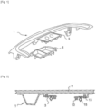
- FIG. 1 shows a defrost duct 1 comprising a support 3 for equipment, for example for a loudspeaker 7 (visible in Figure 3 ) and/or an automatic emergency call system (not shown).
- the support 3 comes integrally with the body of the defrost duct 1.
- the assembly is molded in one piece, for example by injection, in a composite or thermoplastic material.
- the support 3 will therefore carry the loudspeaker 7 but also the loudspeaker bowl 5 in which said loudspeaker 7 is inserted.
- the loudspeaker 7 and the associated loudspeaker bowl 5 are not present on all vehicles, but are installed only on part of the range associated with a given silhouette.
- the panel 9 of the dashboard has or not an opening intended to receive a speaker grille 11.
- the mounting of the speaker 7 and its associated bowl 5 is generally done after an operation of fixing the defrost duct 1 on the panel 9 of the dashboard.
- This fixing operation is, for example, an ultrasonic or vibration welding operation.
- the means of fixing and/or clipping (13, 15) of the loudspeaker bowl and the loudspeaker are mounted by default on the defrost duct 1.
- the figure 2 is a sectional view of an assembly comprising a panel 9 of the dashboard welded to a defrost duct 1 intended for a vehicle without a central speaker. It can be seen that the means for fixing the bowl and the loudspeaker, such as locking nuts 13 and clipping means 15 are present although unused.
- the invention proposes to provide a response to at least one of the drawbacks and/or problems encountered in the prior art.
- the invention aims to propose a solution for adapting a dashboard to the mounting of a central speaker and/or an automatic emergency call system which is simple and economical; and which preferably is more robust than known solutions.
- the subject of the invention is a defrosting duct for a motor vehicle, said defrosting duct comprising a body showing a chute and being intended to be fixed to a dashboard panel, the defrosting duct defrosting is remarkable in that it comprises at least one speaker bowl and in that at least one speaker bowl is integral with said body.
- the speaker bowl(s) have an opening and the defrost duct is made of a thermoplastic material or a composite material with a thermoplastic matrix.
- At least one speaker bowl includes a rim forming the perimeter of the opening of the speaker bowl. Said rim shows a series of ribs for attaching said speaker bowl to a dashboard panel by ultrasonic or vibration welding.
- the invention consists of making the defrost duct carry the loudspeaker bowl instead of the loudspeaker support. Since the means of fixing the loudspeaker and the loudspeaker grille are carried by the loudspeaker support and not by the loudspeaker bowl, these fixings will not be present by default when the dashboard is not equipped with a speaker.
- the speaker support will be added to the defrost duct when attaching the dashboard panel to the defroster duct but only when necessary, i.e. when the dashboard panel edge shows an opening for the speaker or an automatic emergency call system. Also, this configuration is advantageous in that the speaker bowl itself is fixed by welding to the dashboard panel, making the whole thing more robust.
- the invention is remarkable in that it offers a simple and economical response to the problem posed.
- At least one speaker bowl comprises at least one internal separation partition arranged to divide it into at least two compartments. This configuration allows the speaker bowl to receive at least two acoustic devices chosen from at least one loudspeaker and/or an automatic emergency call system.
- At least one speaker bowl comprises at least one fixing interface for fixing a speaker support.
- At least one fixing interface comprises clipping means intended to cooperate with complementary clipping means carried by the loudspeaker support.
- At least one fixing interface is arranged on a peripheral shoulder arranged in the speaker bowl.
- the peripheral shoulder is contained in the loudspeaker bowl, that is to say that the peripheral shoulder is arranged lower than the rim of the loudspeaker bowl intended for its attachment to the panel of the speaker board. edge.
- the subject of the invention is a
- the invention relates to an assembly remarkable in that it comprises a defrost duct according to the first aspect and a loudspeaker support.
- the loudspeaker support is intended to be fixed on the defrost duct and is in the form of a plate showing at least one opening, and comprising at least one fixing interface or means of fixing to a loudspeaker bowl. speaker carried by said defrost duct.
- the plate shows at least two openings and/or the means for fixing to the speaker bowl are clipping means.
- the plate has an upper face and a lower face and the clipping means are in the form of at least one male element projecting from the lower face of the plate.
- the loudspeaker support further comprises clipping means for fixing a loudspeaker grille.
- the clipping means for fixing a loudspeaker grille comprise at least one clipping sleeve intended to receive a clipping foot carried by the loudspeaker grille.
- the loudspeaker support further comprises fixing means intended for fixing a loudspeaker and/or an automatic emergency call system.
- the fixing means for fixing a loudspeaker and/or an automatic emergency call system comprise at least one locking nut.
- the plate showing an upper face and a lower face the loudspeaker support is remarkable in that it comprises a peripheral shoulder rising from the upper face of the plate.
- the speaker support is made of a thermoplastic material or of a composite material with a thermoplastic matrix and the peripheral shoulder shows a series of ribs intended for fixing said speaker support on a board panel. edge by ultrasonic or vibration welding.
- the invention relates to a dashboard with a dashboard panel, remarkable in that the dashboard panel is fixed to a defroster duct according to the first aspect or to an assembly according to the third aspect .
- the invention relates to a motor vehicle remarkable in that it comprises a dashboard with a dashboard panel, remarkable in that the dashboard panel is fixed to a defrost duct according to the first aspect or to a set according to the third aspect.
- the invention relates to a motor vehicle remarkable in that it comprises a dashboard according to the fourth aspect.
- the invention relates to a method of mounting a dashboard according to the fourth aspect, or a dashboard for a motor vehicle according to the fifth aspect, the method comprising a step of fixing a defrost duct on a dashboard panel; the method being remarkable in that the defrost duct is according to the first aspect and in that when the dashboard panel shows an opening facing a speaker bowl carried by said defroster, the method comprises a step of fixing a speaker support to said speaker bowl carried out prior to the step of fixing a defrost duct on a dashboard panel.
- the step of fixing a defrost duct on a dashboard panel is carried out by ultrasonic or vibration welding.
- the step of fixing a loudspeaker support to said loudspeaker bowl is done by clipping.
- the method further comprises a step of fixing an automatic emergency call system and/or a loudspeaker on said loudspeaker support carried out after the The step of fixing a defrost duct to a dashboard panel.
- the method further comprises a step of fixing a loudspeaker grille on said loudspeaker support carried out after the step of fixing an automatic emergency call system and/or of a speaker on said speaker support.
- the invention relates to the use of a defrost duct according to the first aspect and/or of an assembly according to the third aspect for the assembly of an automatic emergency call system and/or a loudspeaker in a motor vehicle; preferably in a motor vehicle according to the fifth aspect.
- the invention relates to the use of a defrost duct according to the first aspect and/or an assembly according to the third aspect for mounting an automatic emergency call system and/or a speaker in a dashboard according to the fourth aspect.
- the term “include” is synonymous with “include” and is not restrictive in that it authorizes the presence of other elements in the defrost duct, the speaker support, the board board or vehicle or other steps in the process to which it relates. It is understood that the term “understand” includes the terms “consist of”. The terms “high” and “low” will be understood in their general sense, the term “low” designating greater proximity to the ground. In the different figures, the same references designate identical or similar elements.
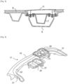
- the defrost duct 17 comprises a body with a general U-shape showing a central part 19 and two side parts 21, said U-shaped body being configured to be open towards the rear of the motor vehicle when the defrost duct 17 is mounted in a motor vehicle.
- the body of the defrosting duct 17 is intended to be fixed to a dashboard panel 9 (visible on the figures 6 And 7 ) and shows a chute 23 extending along the entire length of the body and being intended to be connected to an air conditioning device (not shown).
- the chute 23 is open towards the top and is intended to cooperate with the dashboard panel 9 to form an air distribution channel for defrosting the windshield of the vehicle.
- the defrost duct 17 according to the invention is remarkable in that it comprises at least one loudspeaker bowl 25 and in that at least one loudspeaker bowl 25 is integral with said body.
- the speaker bowl(s) 25 show an opening, open towards the top.
- at least one loudspeaker bowl 25 is arranged at the central part 19 of said body so as to be placed between the two lateral parts 21, that is to say inside said U.
- at least a speaker bowl 25 is integral with the central part 19 of said body.
- the speaker bowl(s) 25 extend from the body of the defrost duct 17.
- At least one loudspeaker bowl 25 comprises at least one internal separation partition 27 arranged to divide it into at least two compartments.
- the speaker bowl 25 can be used for at least two adjacently mounted acoustic devices such as a loudspeaker and an automatic emergency call system (not shown in figures 4 And 5 ).
- the associated loudspeaker support 29 will include at least one opening 31 intended to face one of the compartments; for example, a single opening if only one of the compartments is intended to be used.
- the associated loudspeaker support 29 will comprise at least two openings 31, each intended to face one of the compartments.
- the defrost conduit 17 is preferably made of a thermoplastic material or of a composite material with a thermoplastic matrix.
- a thermoplastic material or the thermoplastic matrix of the composite material from polypropylene (PP), polyethylene (PE), polyphthalamide (PPA), polyetheretherketone (PEEK), polyphenylene sulfide (PPS), polyamide-imide (PAI), polyetherimide (PEI), polyarylamide (PAA), or polyamide (PA) such as for example polyamide 6 (PA 6 or polycaprolactam ) or polyamide 6.6 (PA 6.6 or polyhexamethylene adipamide), or their mixtures.
- the thermoplastic material or the thermoplastic matrix of the composite material is polypropylene or polyamide.
- the defrost duct 17 is assembled with the dashboard panel 9 by ultrasonic or vibration welding.
- Ultrasonic or vibration welding is a technique known to those skilled in the art which will therefore not be described in detail in this specification.
- the parts to be assembled each show a series of ribs at their respective fixing interfaces. High-frequency vibrations are sent to the parts to be assembled via a vibrating tool. Under the effect of the heat generated by the vibrations, the ribs will melt and the materials of the different parts will merge at the fixing interfaces. The welding is thus carried out.
- the loudspeaker bowl(s) 25 being open towards the top, therefore facing the dashboard panel 9, at least one loudspeaker bowl 25 comprises a rim 33 forming the periphery of the the opening of the speaker bowl 25.
- This rim 33 forms an interface for fixing the speaker bowl 25 with the dashboard panel 9.
- the peripheral rim 33 of the speaker bowl shows a series of ribs 35 intended for fixing said speaker bowl 25 to a dashboard panel 9 by ultrasonic or vibration welding.
- At least one speaker bowl 25 comprises at least one fixing interface for fixing a speaker support 29.
- at least one fixing interface comprises clipping means 37 intended to cooperate with complementary clipping means 39 carried by the loudspeaker support 29.
- at least one fixing interface includes an opening 37 for the passage of a clip fixing forming a clipping means 39 carried by the loudspeaker support 29.
- At least one fixing interface for fixing a loudspeaker support 29 is arranged on a peripheral shoulder 41 arranged in the loudspeaker bowl 25.
- the peripheral shoulder is contained in the loudspeaker bowl, that is to say that the peripheral shoulder is arranged lower than the rim of the loudspeaker bowl intended for its attachment to the panel of the speaker board. edge.
- the loudspeaker support 29 is advantageously contained at least in part and preferably in its entirety in the loudspeaker bowl 25. Fastening by clipping is advantageous in that it does not require tools and can therefore be easily carried out when assembling the different parts for welding. Those skilled in the art can nevertheless carry out this fixing by other means.
- the loudspeaker support 29 intended to be fixed on a defrost duct 17 is preferably in the form of a plate showing at least one opening 31 and comprises at least one fixing interface or fixing means and/or clipping 39 to a loudspeaker bowl 25 carried by said defrost conduit 17.
- the plate shows at least two openings 31.
- the means of fixing and/or clipping 39 to the loudspeaker bowl are clipping means 39.
- the plate showing an upper face and a lower face, the clipping means 39 are advantageously in the form of at least one male element projecting from the lower face of the plate.
- the means for fixing the acoustic device(s) and the loudspeaker grille 11 are carried by the loudspeaker support 29. They will therefore not be present by default on all vehicle models but will only be present when they are necessary.
- the loudspeaker support 29 comprises clipping means 15 for fixing a loudspeaker grille 11 by clipping.
- said clipping means 15 comprise at least one clipping sleeve intended to receive a clipping foot 43 carried through the speaker grille 11.
- the clipping socket is oriented to be open upwards, clipping being done by pressing the clipping foot(s) 43 of the speaker grille 11 into the clipping socket(s) of the speaker support.
- the loudspeaker support 29 advantageously comprises fixing means 13 intended for fixing a loudspeaker and/or an automatic emergency call system.
- the fixing means 13 for fixing a loudspeaker and/or an automatic emergency call system comprise at least one locking nut.
- the locking nut(s) are arranged to be opened upwards so as to be accessible through the opening shown by the dashboard panel 9.
- the clipping fixing of the speaker support 29 is a temporary so-called “holding” fixing.
- Final fixation is done by ultrasonic or vibration welding. This configuration is advantageous in terms of the robustness of the assembly and to avoid the generation of parasitic noises coming from vibrations when the vehicle is rolling.
- the loudspeaker support 29 comprises a peripheral shoulder 45 rising from the upper face of the plate.
- This peripheral shoulder 45 forms an interface for fixing the speaker support 29 with the dashboard panel 9.
- the peripheral shoulder 45 of the loudspeaker support 29 shows a series of ribs 47 intended for fixing said loudspeaker support 29 on a panel 9 of a board. edge by ultrasonic or vibration welding.
- the invention is remarkable in that the ultrasonic or vibration welding will weld together at least three parts, namely the dashboard panel 9, the defrost duct 17 including its speaker bowl(s) 25 and the speaker support(s) 29.
- the dashboard thus formed is more robust than those of the prior art in which the speaker bowl was assembled by screwing and not by welding. The elimination of the associated screwing operations further adds to the savings generated by the invention.
- the speaker support 29 is made of a thermoplastic material or of a composite material with a thermoplastic matrix.
- the loudspeaker support 29 is made of the same material as the defrost duct 17.
- the peripheral shoulder 45 shows a series of ribs 47 intended for fixing said loudspeaker support 29 on a dashboard panel 9 by ultrasonic or vibration welding.
- the invention also relates to a method of mounting a dashboard for a vehicle according to the invention, the assembly method involving a defrost duct 17 according to the invention, that is to say comprising a body with a chute 23 and at least one speaker bowl 25 made integrally with said body.
- the method comprises the following steps, given in chronological order: the supply of a dashboard panel 9 and a defrost duct 17 according to the invention. Determining the presence or not of an opening on the dashboard panel 9 intended to be positioned opposite a speaker bowl 25 carried by said defrost duct 17. When the dashboard panel 9 does not show an opening, a step of fixing the defrost duct 17 on the dashboard panel 9 is directly implemented.
- the method comprises an additional step of fixing a loudspeaker support 29 on the loudspeaker bowl(s) 25 intended to be positioned facing the or openings prior to the step of fixing the defrost duct 17 on the dashboard panel 9.
- the fixed loudspeaker support 29 is preferably dimensioned to be contained in the loudspeaker bowl 25.
- the step of fixing a loudspeaker support 29 to a loudspeaker bowl 25 is done by clipping.
- a loudspeaker support 29 is fixed to a loudspeaker bowl 25
- those skilled in the art will benefit from the step of fixing the defrost duct 17 on the dashboard panel 9 either carried out by ultrasonic or vibration welding.
- the assembly process continues with the implementation of a step of fixing a system automatic emergency call and/or a loudspeaker 7 on said loudspeaker support.
- This fixing is advantageously done by screwing.
- the method implements a step of fixing a speaker grille 11 on said speaker support. Fixing the speaker grille 11 is advantageously done by clipping.
Landscapes
- Engineering & Computer Science (AREA)
- Mechanical Engineering (AREA)
- Chemical & Material Sciences (AREA)
- Combustion & Propulsion (AREA)
- Transportation (AREA)
- Physics & Mathematics (AREA)
- Thermal Sciences (AREA)
- Acoustics & Sound (AREA)
- Signal Processing (AREA)
- Fittings On The Vehicle Exterior For Carrying Loads, And Devices For Holding Or Mounting Articles (AREA)
- Details Of Audible-Bandwidth Transducers (AREA)
Description
- L'invention se situe dans le domaine des véhicules automobiles pouvant être équipés d'un haut-parleur et/ou d'un système d'appel d'urgence automatique disposé au niveau de la planche de bord. L'invention s'adresse en particulier au système de montage d'un tel haut-parleur et/ou d'un tel système d'appel d'urgence automatique.
- Les systèmes d'appels d'urgence automatique, ou « e-Call », permettent à une voiture accidentée d'appeler instantanément les services d'urgence via un réseau de téléphone mobile et d'envoyer sa position précise, que les occupants du véhicule soient conscients ou non. Les systèmes d'appels d'urgence automatique sont implantés dans les véhicules destinés au marché européen, et dans certains des véhicules destinés à d'autres marchés. Ils ne sont donc pas implantés dans tous les véhicules produits.
- Le document
DE102016208977 décrit le montage d'un module de type « e-Call » sur la planche de bord d'un véhicule automobile. Le montage s'effectue par un support de montage dédié comprenant une partie de maintien (pour maintenir une unité de commande) et une partie de montage connectée à la partie de maintien de telle sorte que la partie de montage soit courbée vers le haut ou vers le bas à partir de la partie de maintien. - Les documents
US5709601 ,US2011/176689 , etEP0713798 décrivent des planches de bord de véhicule comportant un conduit de dégivrage, et le documentJP2002186077 JP2001310653 - Il est également connu que le support d'un haut-parleur central et/ou d'un système d'appel d'urgence automatique soit porté par un support monté sur le conduit de dégivrage associé à la planche de bord ou venu de matière avec ce dernier.
- Les conduits de dégivrage sont connus de l'homme du métier, par exemple, le document
WO2011/010053 décrit une architecture de planche de bord destinée à être placée sous le pare-brise d'un véhicule automobile. La planche de bord comprend un panneau et une traverse inférieure espacée de ce panneau. Un ensemble est disposé entre les deux qui comprend notamment une ouverture de raccordement avec un dispositif de climatisation et un conduit de dégivrage qui s'étend sous le pare-brise et qui est relié à ladite ouverture. - Il est maintenant fait référence aux
figures 1 à 3 . Lafigure 1 montre un conduit de dégivrage 1 comprenant un support 3 pour un équipement, par exemple pour un haut-parleur 7 (visible enfigure 3 ) et/ou un système d'appel d'urgence automatique (non représenté). Le support 3 est venu de matière avec le corps du conduit de dégivrage 1. L'ensemble est moulé d'une seule pièce par exemple par injection, en un matériau composite ou thermoplastique. - Le support 3 va donc porter le haut-parleur 7 mais également le bol 5 de haut-parleur dans lequel est inséré ledit haut-parleur 7. Le haut-parleur 7 et le bol 5 de haut-parleur associé ne sont pas présents sur tous les véhicules, mais sont installés seulement sur une partie de la gamme associée à une silhouette donnée. En fonction de la présence ou non d'un haut-parleur 7, le panneau 9 de la planche de bord présente ou non une ouverture destinée à recevoir une grille 11 de haut-parleur.
- Le montage du haut-parleur 7 et de son bol 5 associé se fait généralement après une opération de fixation du conduit de dégivrage 1 sur le panneau 9 du tableau de bord. Cette opération de fixation est, par exemple, une opération de soudage par ultrason ou vibration. Ainsi, lors de la préparation du conduit de dégivrage 1, il n'est pas possible de savoir si ledit conduit de dégivrage 1 va être associé à un panneau 9 de planche de bord montrant une ouverture ou non. C'est pourquoi les moyens de fixation et/ou de clippage (13, 15) du bol de haut-parleur et du haut-parleur sont montés par défaut sur le conduit de dégivrage 1. La
figure 2 est une vue en coupe d'un ensemble comprenant un panneau 9 de la planche de bord soudé à un conduit de dégivrage 1 destiné à un véhicule exempt de haut-parleur en voie centrale. On peut voir que les moyens de fixation du bol et du haut-parleur, tels que des écrous de blocage 13 et des moyens de clippage 15 sont présents bien qu'inutilisés. - Pour des raisons d'économies d'échelle, il serait intéressant de pouvoir s'affranchir d'un montage de moyens de fixation et/ou de clippage (13, 15) lorsque cela n'est pas nécessaire, sans pour autant avoir à mettre en oeuvre plusieurs références de conduits de dégivrage 1 en fonction de la gamme du véhicule qui les reçoit, notamment du fait du caractère volumineux de ces derniers.
- L'invention propose d'apporter une réponse à au moins un des inconvénients et/ou problèmes rencontrés dans l'art antérieur. L'invention a pour objectif de proposer une solution pour adapter une planche de bord au montage d'un haut-parleur central et/ou d'un système d'appel d'urgence automatique qui soit simple et économique ; et qui de préférence soit plus robuste que les solutions connues.
- A cet effet et selon un premier aspect, l'invention a pour objet un conduit de dégivrage pour véhicule automobile, ledit conduit de dégivrage comprenant un corps montrant une goulotte et étant destiné à être fixé à un panneau de planche de bord, le conduit de dégivrage est remarquable en ce qu'il comprend au moins un bol de haut-parleur et en ce qu'au moins un bol de haut-parleur est venu de matière avec ledit corps. Le ou les bols de haut-parleur montrent une ouverture et le conduit de dégivrage est réalisé en un matériau thermoplastique ou en un matériau composite avec une matrice thermoplastique. Au moins un bol de haut-parleur comprend un rebord formant le pourtour de l'ouverture du bol de haut-parleur. Ledit rebord montre une série de nervures destinées à la fixation dudit bol de haut-parleur sur un panneau de planche de bord par soudage par ultrason ou vibration.
- Comme on l'aura compris à la lecture de la définition qui vient d'en être donnée, l'invention consiste à faire porter au conduit de dégivrage le bol de haut-parleur au lieu du support de haut-parleur. Puisque les moyens de fixation du haut-parleur et de la grille de haut-parleur sont portés par le support de haut-parleur et non pas par le bol de haut-parleur, ces fixations ne seront pas présentes par défaut lorsque la planche de bord n'est pas équipée d'un haut-parleur. Le support de haut-parleur sera ajouté sur le conduit de dégivrage au moment de la fixation du panneau de planche de bord sur le conduit de dégivrage mais uniquement lorsque c'est nécessaire, c'est-à-dire lorsque le panneau de planche de bord montre une ouverture destinée au haut-parleur ou à un système d'appel d'urgence automatique. Aussi, cette configuration est avantageuse en ce que le bol de haut-parleur en lui-même est fixé par soudage sur le panneau de planche de bord, rendant l'ensemble plus robuste. L'invention est remarquable en ce qu'elle offre une réponse simple et économique à la problématique posée.
- Selon un mode de réalisation, au moins un bol de haut-parleur comprend au moins une cloison de séparation interne agencée pour le diviser en au moins deux compartiments. Cette configuration permet au bol de haut-parleur de recevoir au moins deux dispositifs acoustiques choisis parmi au moins un haut-parleur et/ou un système d'appel d'urgence automatique.
- Selon un mode de réalisation, au moins un bol de haut-parleur comprend au moins une interface de fixation pour la fixation d'un support de haut-parleur.
- De préférence, au moins une interface de fixation comprend des moyens de clippage destinés à coopérer avec des moyens de clippage complémentaires portés par le support de haut-parleur.
- Avantageusement, au moins une interface de fixation est disposée sur un épaulement périphérique agencé dans le bol de haut-parleur. De préférence, l'épaulement périphérique est contenu dans le bol de haut-parleur, c'est-à-dire que l'épaulement périphérique est disposé inférieur au rebord du bol de haut-parleur destiné à sa fixation au panneau de la planche de bord.
- R4 Selon un deuxième aspect, l'invention a pour objet un
- Selon un deuxième aspect, l'invention concerne un ensemble remarquable en ce qu'il comprend un conduit de dégivrage selon le premier aspect et un support de haut-parleur. Le support de haut-parleur est destiné à être fixé sur le conduit de dégivrage et se présente sous forme d'une platine montrant au moins une ouverture, et comprenant au moins une interface de fixation ou des moyens de fixation à un bol de haut-parleur porté par ledit conduit de dégivrage.
- De préférence, la platine montre au moins deux ouvertures et/ou les moyens de fixation au bol de haut-parleur sont des moyens de clippage.
- De préférence, la platine montre une face supérieure et une face inférieure et les moyens de clippage se présentent sous forme d'au moins un élément mâle s'élevant en saillie depuis la face inférieure de la platine.
- Selon un mode de réalisation ; le support de haut-parleur comprend en outre des moyens de clippage pour la fixation d'une grille de haut-parleur. De préférence, les moyens de clippage pour la fixation d'une grille de haut-parleur comprennent au moins une douille de clippage destinée à recevoir un pied de clippage porté par la grille de haut-parleur.
- Selon un mode de réalisation ; le support de haut-parleur comprend en outre des moyens de fixation destinés à la fixation d'un haut-parleur et/ou d'un système d'appel d'urgence automatique. De préférence, les moyens de fixation pour la fixation d'un haut-parleur et/ou d'un système d'appel d'urgence automatique comprennent au moins un écrou de blocage.
- Selon un mode de réalisation ; la platine montrant une face supérieure et une face inférieure, le support de haut-parleur est remarquable en ce qu'il comprend un épaulement périphérique s'élevant depuis la face supérieure de la platine. De préférence, le support de haut-parleur est réalisé en un matériau thermoplastique ou en un matériau composite avec une matrice thermoplastique et l'épaulement périphérique montre une série de nervures destinées à la fixation dudit support de haut-parleur sur un panneau de planche de bord par soudage par ultrason ou vibration.
- Selon un troisième aspect, l'invention concerne une planche de bord avec un panneau de planche de bord, remarquable en ce que le panneau de planche de bord est fixé à un conduit de dégivrage selon le premier aspect ou à un ensemble selon le troisième aspect.
- Selon un quatrième aspect, l'invention concerne un véhicule automobile remarquable en ce qu'il comprend une planche de bord avec un panneau de planche de bord, remarquable en ce que le panneau de planche de bord est fixé à un conduit de dégivrage selon le premier aspect ou à un ensemble selon le troisième aspect.
- Par exemple, l'invention concerne un véhicule automobile remarquable en ce qu'il comprend une planche de bord selon le quatrième aspect.
- Selon un cinquième aspect, l'invention concerne un procédé de montage d'une planche de bord selon le quatrième aspect, ou une planche de bord pour véhicule automobile selon le cinquième aspect, le procédé comprenant une étape de fixation d'un conduit de dégivrage sur un panneau de planche de bord ; le procédé étant remarquable en ce que le conduit de dégivrage est selon le premier aspect et en ce que lorsque le panneau de planche de bord montre une ouverture en regard d'un bol de haut-parleur porté par ledit de dégivrage, le procédé comprend une étape de fixation d'un support de haut-parleur sur ledit bol de haut-parleur réalisée préalablement à l'étape de fixation d'un conduit de dégivrage sur un panneau de planche de bord.
- Selon une mise en oeuvre de l'invention, l'étape de fixation d'un conduit de dégivrage sur un panneau de planche de bord est réalisée par soudage par ultrason ou vibration.
- Selon une mise en oeuvre de l'invention, l'étape de fixation d'un support de haut-parleur sur ledit bol de haut-parleur se fait par clippage.
- Selon une mise en oeuvre de l'invention, le procédé comprend en outre une étape de fixation d'un système d'appel d'urgence automatique et/ou d'un haut-parleur sur ledit support de haut-parleur réalisée postérieurement à l'étape de fixation d'un conduit de dégivrage sur un panneau de planche de bord.
- De manière préférentielle, le procédé comprend en outre une étape de fixation d'une grille de haut-parleur sur ledit support de haut-parleur réalisée postérieurement à l'étape de fixation d'un système d'appel d'urgence automatique et/ou d'un haut-parleur sur ledit support de haut-parleur.
- Selon un septième aspect, l'invention concerne l'utilisation d'un conduit de dégivrage selon le premier aspect et/ou d'un ensemble selon le troisième aspect pour le montage d'un système d'appel d'urgence automatique et/ou d'un haut-parleur dans un véhicule automobile ; de préférence dans un véhicule automobile selon le cinquième aspect.
- Par exemple, l'invention concerne l'utilisation d'un conduit de dégivrage selon le premier aspect et/ou d'un ensemble selon le troisième aspect pour le montage d'un système d'appel d'urgence automatique et/ou d'un haut-parleur dans une planche de bord selon le quatrième aspect.
- L'invention sera bien comprise et d'autres aspects et avantages apparaîtront clairement à la lecture de la description qui suit donnée à titre d'exemple et en références aux figures annexées sur lesquelles :
- [
Fig.1 ] Lafigure 1 est une vue en perspective d'un conduit de dégivrage selon l'art antérieur et son bol de haut-parleur associé. - [
Fig. 2 ] Lafigure 2 est une vue simplifiée en coupe selon la direction transversale d'une planche de bord selon l'art antérieur dépourvue de haut-parleur. - [
Fig. 3 ] Lafigure 3 est une vue simplifiée en coupe selon la direction transversale d'une planche de bord selon l'art antérieur avec un haut-parleur. - [
Fig.4 ] Lafigure 4 est une vue en perspective d'un conduit de dégivrage selon l'invention et son support de haut-parleur associé. - [
Fig.5 ] Lafigure 5 est une vue en perspective d'un support de haut-parleur monté dans le bol de haut-parleur d'un conduit de dégivrage selon l'invention. - [
Fig. 6 ] Lafigure 6 est une vue simplifiée en coupe selon la direction transversale d'une planche de bord selon l'invention dépourvue de haut-parleur. - [
Fig. 7 ] Lafigure 7 est une vue simplifiée en coupe selon la direction transversale d'une planche de bord selon l'invention avec un haut-parleur. - Dans la description qui suit, le terme « comprendre » est synonyme de « inclure » et n'est pas limitatif en ce qu'il autorise la présence d'autres éléments dans le conduit de dégivrage, le support de haut-parleur, la planche de bord ou le véhicule ou d'autres étapes dans le procédé auquel il se rapporte. Il est entendu que le terme « comprendre » inclut les termes « consister en ». Les termes « haut » et « bas » s'entendront dans leur sens général, le terme « bas » désignant une proximité avec le sol plus importante. Sur les différentes figures, les mêmes références désignent des éléments identiques ou similaires.
- Les
figures 1 à 3 ayant été décrites en partie introductive, on se référera à présent à lafigure 4 illustrant un conduit de dégivrage 17 selon l'invention destiné à être implanté sous le pare-brise avant d'un véhicule automobile. Le conduit de dégivrage 17 comprend un corps avec une forme générale en U montrant une partie centrale 19 et deux parties latérales 21, ledit corps en forme de U étant configuré pour être ouvert en direction de l'arrière du véhicule automobile lorsque le conduit de dégivrage 17 est monté dans un véhicule automobile. Le corps du conduit de dégivrage 17 est destiné à être fixé à un panneau 9 de planche de bord (visible sur lesfigures 6 et7 ) et montre une goulotte 23 s'étendant selon toute la longueur du corps et étant destinée à être reliée à un dispositif de climatisation (non représenté). La goulotte 23 est ouverte en direction du haut et est destinée à coopérer avec le panneau 9 de planche de bord pour former un canal de distribution d'air en vue du dégivrage du pare-brise du véhicule. - Le conduit de dégivrage 17 selon l'invention est remarquable en ce qu'il comprend au moins un bol 25 de haut-parleur et en ce qu'au moins un bol 25 de haut-parleur est venu de matière avec ledit corps. Le ou les bols 25 de haut-parleur montrent une ouverture, ouverte en direction du haut. De préférence, et comme illustré sur la
figure 4 , au moins un bol 25 de haut-parleur est agencé au niveau la partie centrale 19 dudit corps de manière à être placé entre les deux parties latérales 21, c'est-à-dire à l'intérieur dudit U. Ainsi, au moins un bol 25 de haut-parleur est venu de matière avec la partie centrale 19 dudit corps. Le ou les bols 25 de haut-parleur s'étendent en saillie depuis le corps du conduit de dégivrage 17. - Selon un mode de réalisation préférentiel, au moins un bol 25 de haut-parleur comprend au moins une cloison 27 de séparation interne agencée pour le diviser en au moins deux compartiments. Ainsi, le bol 25 de haut-parleur peut être utilisé pour au moins deux dispositifs acoustiques montés adjacents tels qu'un haut-parleur et un système d'appel d'urgence automatique (non représentés en
figures 4 et5 ). Le support 29 de haut-parleur associé comprendra au moins une ouverture 31 destinée à être en regard d'un des compartiments ; par exemple, une seule ouverture si un seul des compartiments est destiné à être utilisé. De préférence, le support 29 de haut-parleur associé comprendra au moins deux ouvertures 31 chacune étant destinée à être en regard d'un des compartiments. - Le conduit de dégivrage 17 est préférentiellement réalisé en un matériau thermoplastique ou en un matériau composite avec une matrice thermoplastique. Par exemple, l'homme du métier aura avantage à sélectionner le matériau thermoplastique ou la matrice thermoplastique du matériau composite parmi le polypropylene (PP), le polyethylene (PE), le polyphtalamide (PPA), le polyetherethercétone (PEEK), polysulfure de phénylène (PPS), le polyamide-imide (PAI), le polyetherimide (PEI), le polyarylamide (PAA), ou le polyamide (PA) tel que par exemple du polyamide 6 (PA 6 ou polycaprolactame) ou du polyamide 6.6 (PA 6.6 ou polyhexaméthylène adipamide), ou leurs mélanges. De préférence, le matériau thermoplastique ou la matrice thermoplastique du matériau composite est du polypropylène ou du polyamide.
- Selon l'invention, le conduit de dégivrage 17 est assemblé avec le panneau 9 de planche de bord par soudage par ultrason ou vibration. Le soudage par ultrason ou vibration est une technique connue de l'homme du métier qui ne sera donc pas décrite en détail dans le présent mémoire. On se contentera de préciser qu'il s'agit d'une technique d'assemblage par soudage de pièces en matériau thermoplastique montrant un point de fusion donné. Avantageusement, les pièces à assembler montrent chacune une série de nervures au niveau de leurs interfaces de fixation respectives. Des vibrations haute-fréquence sont envoyées aux pièces à assembler par le biais d'un outil vibrant. Sous l'effet de la chaleur engendrée par les vibrations, les nervures vont fondre et les matériaux des différentes pièces vont fusionner au niveau des interfaces de fixation. La soudure est ainsi réalisée.
- Conformément à l'invention, le ou les bols 25 de haut-parleur étant ouverts en direction du haut, donc en regard du panneau 9 de planche de bord, au moins un bol 25 de haut-parleur comprend un rebord 33 formant le pourtour de l'ouverture du bol 25 de haut-parleur. Ce rebord 33 forme une interface de fixation du bol 25 de haut-parleur avec le panneau 9 de planche de bord. Conformément à l'invention, le rebord 33 périphérique du bol de haut-parleur montre une série de nervures 35 destinées à la fixation dudit bol 25 de haut-parleur sur un panneau 9 de planche de bord par soudage par ultrason ou vibration.
- Selon un mode de réalisation, au moins un bol 25 de haut-parleur comprend au moins une interface de fixation pour la fixation d'un support 29 de haut-parleur. De préférence, au moins une interface de fixation comprend des moyens de clippage 37 destinés à coopérer avec des moyens de clippage 39 complémentaires portés par le support 29 de haut-parleur. Par exemple, au moins une interface de fixation comprend un ajour 37 pour le passage d'un clip de fixation formant un moyen de clippage 39 porté par le support 29 de haut-parleur.
- Selon un mode de réalisation préféré de l'invention, au moins une interface de fixation pour la fixation d'un support 29 de haut-parleur est disposée sur un épaulement 41 périphérique agencé dans le bol 25 de haut-parleur. De préférence, l'épaulement périphérique est contenu dans le bol de haut-parleur, c'est-à-dire que l'épaulement périphérique est disposé inférieur au rebord du bol de haut-parleur destiné à sa fixation au panneau de la planche de bord. Ainsi, le support 29 de haut-parleur est avantageusement contenu au moins en partie et de préférence dans son intégralité dans le bol 25 de haut-parleur. La fixation par clippage est avantageuse en ce qu'elle ne nécessite pas d'outil est peut donc être réalisée facilement au moment de l'assemblage des différentes pièces en vue de leur soudure. L'homme du métier peut néanmoins effectuer cette fixation par d'autres moyens.
- Ainsi, le support 29 de haut-parleur destiné à être fixé sur un conduit de dégivrage 17 se présente préférentiellement sous forme d'une platine montrant au moins une ouverture 31 et comprend au moins une interface de fixation ou des moyens de fixation et/ou de clippage 39 à un bol 25 de haut-parleur porté par ledit conduit de dégivrage 17. De préférence, la platine montre au moins deux ouvertures 31. Avantageusement, les moyens de fixation et/ou de clippage 39 au bol de haut-parleur sont des moyens de clippage 39. La platine montrant une face supérieure et une face inférieure, les moyens de clippage 39 se présentent avantageusement sous forme d'au moins un élément mâle s'élevant en saillie depuis la face inférieure de la platine.
- Comme on l'aura compris, les moyens de fixation du ou des dispositifs acoustiques et de la grille 11 de haut-parleur sont portés par le support 29 de haut-parleur. Ils ne seront donc pas présents par défaut sur tous les modèles de véhicule mais seront présent uniquement lorsqu'ils sont nécessaires.
- Ainsi, avantageusement, le support 29 de haut-parleur selon l'invention comprend des moyens de clippage 15 pour la fixation par clippage d'une grille 11 de haut-parleur. De préférence, lesdits moyens de clippage 15 comprennent au moins une douille de clippage destinée à recevoir un pied 43 de clippage porté par la grille 11 de haut-parleur. La douille de clippage est orientée pour être ouverte vers le haut, le clippage se faisant par enfoncement du ou des pieds 43 de clippage de la grille 11 de haut-parleur dans la ou les douilles de clippage du support de haut-parleur.
- De même, le support 29 de haut-parleur selon l'invention comprend avantageusement des moyens de fixation 13 destinés à la fixation d'un haut-parleur et/ou d'un système d'appel d'urgence automatique. De préférence, les moyens de fixation 13 pour la fixation d'un haut-parleur et/ou d'un système d'appel d'urgence automatique comprennent au moins un écrou de blocage. Le ou les écrous de blocage sont agencés pour être ouverts vers le haut de manière à être accessibles au travers de l'ouverture montrée par le panneau 9 de planche de bord.
- Préférentiellement, la fixation par clippage du support 29 de haut-parleur est une fixation temporaire dite « de maintien ». La fixation définitive se fait par soudage par ultrason ou vibration. Cette configuration est avantageuse en termes de robustesse de l'ensemble et pour éviter la génération de bruits parasites en provenance de vibrations lors du roulage du véhicule.
- Ainsi, selon une mise en oeuvre préférée, la platine montrant une face supérieure et une face inférieure, le support 29 de haut-parleur comprend un épaulement 45 périphérique s'élevant depuis la face supérieure de la platine. Cet épaulement 45 périphérique forme une interface de fixation du support 29 de haut-parleur avec le panneau 9 de planche de bord. A cette fin, l'homme du métier aura avantage à ce que l'épaulement 45 périphérique du support 29 de haut-parleur montre une série de nervures 47 destinées à la fixation dudit support 29 de haut-parleur sur un panneau 9 de planche de bord par soudage par ultrason ou vibration.
- On notera que dans ses modes de réalisation préférés, l'invention est remarquable en ce que la soudure par ultrason ou vibration va souder entre-elles au moins trois pièces, à savoir le panneau 9 de planche de bord, le conduit de dégivrage 17 incluant son ou ses bols 25 de haut-parleur et le ou les supports 29 de haut-parleur. La planche de bord ainsi formée est plus robuste que celles de l'art antérieur dans lesquelles le bol de haut-parleur était assemblé par vissage et non pas par soudage. La suppression des opérations de vissage associées ajoute encore aux économies engendrées par l'invention.
- Ainsi, selon un mode de réalisation préféré, le support 29 de haut-parleur est réalisé en un matériau thermoplastique ou en un matériau composite avec une matrice thermoplastique. Par exemple, le support 29 de haut-parleur est réalisé dans le même matériau que le conduit de dégivrage 17. De préférence, l'épaulement 45 périphérique montre une série de nervures 47 destinées à la fixation dudit support 29 de haut-parleur sur un panneau 9 de planche de bord par soudage par ultrason ou vibration.
- L'invention concerne aussi un procédé de montage d'une planche de bord pour véhicule selon l'invention, le procédé de montage impliquant un conduit de dégivrage 17 selon l'invention, c'est-à-dire comprenant un corps avec une goulotte 23 et au moins un bol 25 de haut-parleur venu de matière avec ledit corps. Le procédé comprend les étapes suivantes, données dans un ordre chronologique : l'approvisionnement d'un panneau 9 de planche de bord et d'un conduit de dégivrage 17 selon l'invention. La détermination de la présence ou non d'une ouverture sur le panneau 9 de planche de bord destinée à être positionnée en regard d'un bol 25 de haut-parleur porté par ledit conduit de dégivrage 17. Lorsque le panneau 9 de planche de bord ne montre pas d'ouverture, une étape de fixation du conduit de dégivrage 17 sur le panneau 9 de planche de bord est directement mise en oeuvre. Lorsque le panneau 9 de planche de bord montre au moins une ouverture, le procédé comprend une étape supplémentaire de fixation d'un support 29 de haut-parleur sur le ou les bols 25 de haut-parleur destinés à être positionnés en regard de la ou des ouvertures préalablement à l'étape de fixation du conduit de dégivrage 17 sur le panneau 9 de planche de bord. Le support 29 de haut-parleur fixé est préférentiellement dimensionné pour être contenu dans le bol 25 de haut-parleur. De préférence, l'étape de fixation d'un support 29 de haut-parleur sur un bol 25 de haut-parleur se fait par clippage.
- Qu'un support 29 de haut-parleur soit fixé ou non à un bol 25 de haut-parleur, l'homme du métier aura avantage à ce que l'étape de fixation du conduit de dégivrage 17 sur le panneau 9 de planche de bord soit réalisée par soudage par ultrason ou vibration.
- Lorsque le panneau 9 de planche de bord est soudé avec le conduit de dégivrage 17 et avec un ou plusieurs supports 29 de haut-parleur, le procédé de montage se poursuit avec la mise en oeuvre d'une étape de fixation d'un système d'appel d'urgence automatique et/ou d'un haut-parleur 7 sur ledit support de haut-parleur. Cette fixation se fait avantageusement par vissage. Puis le procédé met en oeuvre une étape de fixation d'une grille 11 de haut-parleur sur ledit support de haut-parleur. La fixation de la grille 11 de haut-parleur se fait avantageusement par clippage.
Claims (8)
- Conduit de dégivrage (17) pour véhicule automobile, ledit conduit de dégivrage (17) comprenant un corps montrant une goulotte (23) et étant destiné à être fixé à un panneau (9) de planche de bord, le conduit de dégivrage (17) comprenant au moins un bol (25) de haut-parleur montrant une ouverture, au moins un bol (25) de haut-parleur est venu de matière avec ledit corps, le conduit de dégivrage (17) est caractérisé en ce qu'il est réalisé en un matériau thermoplastique ou en un matériau composite avec une matrice thermoplastique et en ce qu'au moins un bol (25) de haut-parleur comprend un rebord (33) formant le pourtour de l'ouverture du bol (25) de haut-parleur ; ledit rebord (33) montrant une série de nervures (35) destinées à la fixation dudit bol (25) de haut-parleur sur un panneau (9) de planche de bord par soudage par ultrason ou vibration ; de préférence, au moins un bol (25) de haut-parleur comprend au moins une cloison (27) de séparation interne agencée pour le diviser en au moins deux compartiments.
- Conduit de dégivrage (17) selon l'une des revendications 1 caractérisé en ce qu'au moins un bol (25) de haut-parleur comprend au moins une interface de fixation pour la fixation d'un support (29) de haut-parleur ; de préférence, au moins une interface de fixation comprend des moyens de clippage (37) destinés à coopérer avec des moyens de clippage (39) complémentaires portés par le support (29) de haut-parleur et/ou au moins une interface de fixation est disposée sur un épaulement (41) périphérique agencé dans le bol (25) de haut-parleur.
- Ensemble comprenant un conduit de dégivrage (17) selon l'une des revendications 1 à 2 et un support (29) de haut-parleur destiné à être fixé sur ledit conduit de dégivrage (17), le support (29) se présentant sous forme d'une platine montrant au moins une ouverture (31) et comprenant au moins une interface de fixation ou des moyens de fixation à un bol (25) de haut-parleur porté par ledit conduit de dégivrage (17) ; de préférence, la platine montre au moins deux ouvertures (31) et/ou les moyens de fixation au bol (25) de haut-parleur sont des moyens de clippage.
- Ensemble suivant la revendication précédente, comprenant en outre des moyens de clippage (15) pour la fixation d'une grille (11) de haut-parleur et/ou en ce qu'il comprend en outre des moyens de fixation (13) destinés à la fixation d'un haut-parleur et/ou d'un système d'appel d'urgence automatique ; de préférence les moyens de fixation (13) pour la fixation d'un haut-parleur et/ou d'un système d'appel d'urgence automatique comprennent au moins un écrou de blocage (13).
- Ensemble suivant l'une des revendications 3 ou 4, dont la platine montre une face supérieure et une face inférieure, le support (29) comprenant un épaulement (45) périphérique s'élevant depuis la face supérieure de la platine ; de préférence, le support (29) de haut-parleur est réalisé en un matériau thermoplastique ou en un matériau composite avec une matrice thermoplastique et l'épaulement périphérique (45) montre une série de nervures (47) destinées à la fixation dudit support (29) de haut-parleur sur un panneau (9) de planche de bord par soudage par ultrason ou vibration
- Véhicule automobile caractérisé en ce qu'il comprend une planche de bord avec un panneau (9) de planche de bord caractérisé en ce que le panneau (9) de planche de bord est fixé à un conduit de dégivrage (17) selon l'une des revendications 1 à 2 ou à un ensemble selon l'une des revendications de 3 à 5.
- Procédé de montage d'une planche de bord pour véhicule automobile selon la revendication 6, le procédé comprenant une étape de fixation d'un conduit de dégivrage (17) sur un panneau (9) de planche de bord ; le procédé étant caractérisé en ce que le conduit de dégivrage (17) est selon l'une des revendications 1 à 2 et en ce que lorsque le panneau (9) de planche de bord montre une ouverture en regard d'un bol (25) de haut-parleur porté par ledit conduit de dégivrage (17), le procédé comprend une étape de fixation d'un support (29) de haut-parleur sur ledit bol (25) de haut-parleur réalisée préalablement à l'étape de fixation d'un conduit de dégivrage (17) sur un panneau (9) de planche de bord, , l'étape de fixation du conduit de dégivrage (17) sur le panneau (9) de planche de bord étant réalisée par soudage par ultrason ou vibration.
- Procédé selon la revendication 7 caractérisé en ce qu'il comprend en outre une étape de fixation d'un système d'appel d'urgence automatique et/ou d'un haut-parleur (7) sur ledit support (29) de haut-parleur réalisée postérieurement à l'étape de fixation d'un conduit de dégivrage (17) sur un panneau (9) de planche de bord ; de préférence, il comprend en outre une étape de fixation d'une grille (11) de haut-parleur sur ledit support (29) de haut-parleur réalisée postérieurement à l'étape de fixation d'un système d'appel d'urgence automatique et/ou d'un haut-parleur (7) sur ledit support (29) de haut-parleur.
Applications Claiming Priority (2)
| Application Number | Priority Date | Filing Date | Title |
|---|---|---|---|
| FR2005523A FR3110514B1 (fr) | 2020-05-25 | 2020-05-25 | Implantation d’un haut-parleur et/ou d’un système d’appel d’urgence automatique dans la planche de bord d’un véhicule automobile |
| PCT/FR2021/050730 WO2021240083A1 (fr) | 2020-05-25 | 2021-04-27 | Implantation d'un haut-parleur et/ou d'un système d'appel d'urgence automatique dans la planche de bord d'un véhicule automobile |
Publications (2)
| Publication Number | Publication Date |
|---|---|
| EP4157677A1 EP4157677A1 (fr) | 2023-04-05 |
| EP4157677B1 true EP4157677B1 (fr) | 2024-07-17 |
Family
ID=73038058
Family Applications (1)
| Application Number | Title | Priority Date | Filing Date |
|---|---|---|---|
| EP21732396.3A Active EP4157677B1 (fr) | 2020-05-25 | 2021-04-27 | Implantation d'un haut-parleur et/ou d'un système d'appel d'urgence automatique dans la planche de bord d'un véhicule automobile |
Country Status (4)
| Country | Link |
|---|---|
| EP (1) | EP4157677B1 (fr) |
| CN (1) | CN115697772A (fr) |
| FR (1) | FR3110514B1 (fr) |
| WO (1) | WO2021240083A1 (fr) |
Family Cites Families (19)
| Publication number | Priority date | Publication date | Assignee | Title |
|---|---|---|---|---|
| NL6804718A (fr) | 1968-04-04 | 1969-10-07 | ||
| US4032725A (en) * | 1976-09-07 | 1977-06-28 | Motorola, Inc. | Speaker mounting |
| JPS57143909U (fr) * | 1981-03-05 | 1982-09-09 | ||
| JPH01240341A (ja) * | 1988-03-23 | 1989-09-25 | Mazda Motor Corp | 車両用スピーカ取付構造 |
| GB9423776D0 (en) * | 1994-11-25 | 1995-01-11 | Acg Deutschland Gmbh | Dashboard assembly |
| EP0713798B1 (fr) * | 1994-11-25 | 1998-04-29 | Delphi Automotive Systems Deutschland GmbH | Ensemble de tableau de bord |
| JP2952850B2 (ja) * | 1996-09-18 | 1999-09-27 | ダイムラー−ベンツ・アクチエンゲゼルシヤフト | 計器盤 |
| JPH11180187A (ja) * | 1997-12-22 | 1999-07-06 | Inoac Corporation:Kk | 車両用インストルメントパネル |
| JP3693885B2 (ja) * | 2000-04-28 | 2005-09-14 | 日産車体株式会社 | インストルメントパネル |
| JP3997266B2 (ja) * | 2000-12-15 | 2007-10-24 | 株式会社ケンウッド | スピーカ装置、スピーカ装置の取付構造及びスピーカ装置の取付構造 |
| WO2009050820A1 (fr) * | 2007-10-19 | 2009-04-23 | Pioneer Corporation | Elément d'installation de haut-parleur et structure de fixation de haut-parleur |
| FR2948325B1 (fr) | 2009-07-21 | 2013-03-29 | Faurecia Interieur Ind | Structure de planche de bord de vehicule automobile et vehicule automobile comportant une telle structure. |
| US8488818B2 (en) * | 2010-01-15 | 2013-07-16 | Nissan North America, Inc. | Interior structural assembly for a vehicle |
| DE102010005028B4 (de) * | 2010-01-20 | 2023-08-10 | Dr. Ing. H.C. F. Porsche Aktiengesellschaft | Aufnahmeeinrichtung für Lautsprecher in einem Kraftfahrzeug |
| DE102010005326B4 (de) * | 2010-01-22 | 2018-07-05 | Dr. Ing. H.C. F. Porsche Aktiengesellschaft | Einstückiges Abdeckelement |
| JP6324215B2 (ja) * | 2014-05-29 | 2018-05-16 | カルソニックカンセイ株式会社 | グリル装置 |
| JP6485223B2 (ja) | 2015-05-28 | 2019-03-20 | スズキ株式会社 | コントローラ取付構造 |
| JP6638592B2 (ja) * | 2016-07-26 | 2020-01-29 | 三菱自動車エンジニアリング株式会社 | 車両のアンテナ取付構造 |
| CN206264799U (zh) * | 2016-12-02 | 2017-06-20 | 上海汽车集团股份有限公司 | 汽车仪表板结构及汽车 |
-
2020
- 2020-05-25 FR FR2005523A patent/FR3110514B1/fr active Active
-
2021
- 2021-04-27 CN CN202180038221.6A patent/CN115697772A/zh active Pending
- 2021-04-27 EP EP21732396.3A patent/EP4157677B1/fr active Active
- 2021-04-27 WO PCT/FR2021/050730 patent/WO2021240083A1/fr not_active Ceased
Also Published As
| Publication number | Publication date |
|---|---|
| WO2021240083A1 (fr) | 2021-12-02 |
| FR3110514B1 (fr) | 2023-10-06 |
| CN115697772A (zh) | 2023-02-03 |
| FR3110514A1 (fr) | 2021-11-26 |
| EP4157677A1 (fr) | 2023-04-05 |
Similar Documents
| Publication | Publication Date | Title |
|---|---|---|
| FR2955529A1 (fr) | Element de recouvrement pour tableau de bord d'un vehicule automobile | |
| FR2860278A1 (fr) | Bride de fixation pour tuyau de transport de fluide | |
| EP2471690B1 (fr) | Système de fixation d'une télécommande de boîtier électronique dans un véhicule automobile | |
| FR3063468A1 (fr) | Platine d’attache et de guidage pour tuyaux et/ou faisceaux cheminant a l’interieur d’un montant de baie. | |
| WO2021019157A1 (fr) | Déflecteur aérodynamique destiné à être fixé contre le soubassement de caisse d'un véhicule | |
| EP4157677B1 (fr) | Implantation d'un haut-parleur et/ou d'un système d'appel d'urgence automatique dans la planche de bord d'un véhicule automobile | |
| FR2768099A1 (fr) | Siege de vehicule dote de haut-parleurs | |
| WO2003052341A1 (fr) | Assemblage perfectionne pour maintenir un equipement de vehicule automobile et preserver cet equipement en cas de choc | |
| FR3058923A1 (fr) | Coiffe de pedale automobile surmoulee autour d'un ergot et son procede de fabrication | |
| WO2015090989A1 (fr) | Ensemble comportant une traverse de planche de bord pour véhicule automobile et deux supports latéraux permettant de fixer cette traverse à la caisse du véhicule | |
| EP3853111B1 (fr) | Véhicule comprenant une jupe de pare-chocs avec des pattes de fixation à un deflecteur montrant une base élargie | |
| EP3870498B1 (fr) | Véhicule automobile avec déflecteur sous-plancher a deux niveaux | |
| WO2020025870A1 (fr) | Vehicule avec deflecteur arriere sous-plancher montrant un chanfrein | |
| EP4508873A1 (fr) | Grille de haut-parleur avec fonction de directivite sonore | |
| FR3078030A1 (fr) | Dispositif de guidage a coulissement d’un appui-tete sur le dossier integrant des moyens assurant le transit de signaux electriques. | |
| FR3050600A1 (fr) | Dispositif de diffusion de sons a radiateurs passifs et event bass-reflex. | |
| EP3576423A1 (fr) | Haut-parleur comprenant des moyens de pré-maintien avant fixation sur une pièce réceptrice | |
| FR3120579A1 (fr) | Support d’un chargeur de batterie électrique d’un véhicule automobile | |
| FR3072923B1 (fr) | Traverse de securite pour un vehicule | |
| WO2019207222A1 (fr) | Embase de montage a pivotement pour accoudoir de dossier de banquette dotee d'un element metallique d'ancrage anti-basculement. | |
| EP0957285B1 (fr) | Support hydroélastique, notamment pour la suspension d'un groupe motopropulseur dans la caisse d'un véhicule automobiles | |
| EP3623213B1 (fr) | Siège de véhicule équipé d'une tablette amovible et véhicule comprenant un tel siège | |
| EP4299372A1 (fr) | Elément de siège et siège de véhicule automobile | |
| FR3148329A1 (fr) | Dispositif de câblage pour un véhicule automobile | |
| FR3162412A1 (fr) | Ensemble de freinage de vehicule automobile |
Legal Events
| Date | Code | Title | Description |
|---|---|---|---|
| STAA | Information on the status of an ep patent application or granted ep patent |
Free format text: STATUS: UNKNOWN |
|
| STAA | Information on the status of an ep patent application or granted ep patent |
Free format text: STATUS: THE INTERNATIONAL PUBLICATION HAS BEEN MADE |
|
| PUAI | Public reference made under article 153(3) epc to a published international application that has entered the european phase |
Free format text: ORIGINAL CODE: 0009012 |
|
| STAA | Information on the status of an ep patent application or granted ep patent |
Free format text: STATUS: REQUEST FOR EXAMINATION WAS MADE |
|
| 17P | Request for examination filed |
Effective date: 20221121 |
|
| AK | Designated contracting states |
Kind code of ref document: A1 Designated state(s): AL AT BE BG CH CY CZ DE DK EE ES FI FR GB GR HR HU IE IS IT LI LT LU LV MC MK MT NL NO PL PT RO RS SE SI SK SM TR |
|
| DAV | Request for validation of the european patent (deleted) | ||
| DAX | Request for extension of the european patent (deleted) | ||
| STAA | Information on the status of an ep patent application or granted ep patent |
Free format text: STATUS: EXAMINATION IS IN PROGRESS |
|
| 17Q | First examination report despatched |
Effective date: 20230913 |
|
| RAP3 | Party data changed (applicant data changed or rights of an application transferred) |
Owner name: STELLANTIS AUTO SAS |
|
| GRAP | Despatch of communication of intention to grant a patent |
Free format text: ORIGINAL CODE: EPIDOSNIGR1 |
|
| STAA | Information on the status of an ep patent application or granted ep patent |
Free format text: STATUS: GRANT OF PATENT IS INTENDED |
|
| INTG | Intention to grant announced |
Effective date: 20240306 |
|
| GRAS | Grant fee paid |
Free format text: ORIGINAL CODE: EPIDOSNIGR3 |
|
| GRAA | (expected) grant |
Free format text: ORIGINAL CODE: 0009210 |
|
| STAA | Information on the status of an ep patent application or granted ep patent |
Free format text: STATUS: THE PATENT HAS BEEN GRANTED |
|
| AK | Designated contracting states |
Kind code of ref document: B1 Designated state(s): AL AT BE BG CH CY CZ DE DK EE ES FI FR GB GR HR HU IE IS IT LI LT LU LV MC MK MT NL NO PL PT RO RS SE SI SK SM TR |
|
| REG | Reference to a national code |
Ref country code: CH Ref legal event code: EP |
|
| REG | Reference to a national code |
Ref country code: DE Ref legal event code: R096 Ref document number: 602021015860 Country of ref document: DE |
|
| REG | Reference to a national code |
Ref country code: IE Ref legal event code: FG4D Free format text: LANGUAGE OF EP DOCUMENT: FRENCH |
|
| REG | Reference to a national code |
Ref country code: DE Ref legal event code: R084 Ref document number: 602021015860 Country of ref document: DE |
|
| REG | Reference to a national code |
Ref country code: GB Ref legal event code: 746 Effective date: 20241003 |
|
| REG | Reference to a national code |
Ref country code: LT Ref legal event code: MG9D |
|
| REG | Reference to a national code |
Ref country code: NL Ref legal event code: MP Effective date: 20240717 |
|
| PG25 | Lapsed in a contracting state [announced via postgrant information from national office to epo] |
Ref country code: PT Free format text: LAPSE BECAUSE OF FAILURE TO SUBMIT A TRANSLATION OF THE DESCRIPTION OR TO PAY THE FEE WITHIN THE PRESCRIBED TIME-LIMIT Effective date: 20241118 |
|
| REG | Reference to a national code |
Ref country code: AT Ref legal event code: MK05 Ref document number: 1703821 Country of ref document: AT Kind code of ref document: T Effective date: 20240717 |
|
| PG25 | Lapsed in a contracting state [announced via postgrant information from national office to epo] |
Ref country code: NL Free format text: LAPSE BECAUSE OF FAILURE TO SUBMIT A TRANSLATION OF THE DESCRIPTION OR TO PAY THE FEE WITHIN THE PRESCRIBED TIME-LIMIT Effective date: 20240717 |
|
| PG25 | Lapsed in a contracting state [announced via postgrant information from national office to epo] |
Ref country code: PT Free format text: LAPSE BECAUSE OF FAILURE TO SUBMIT A TRANSLATION OF THE DESCRIPTION OR TO PAY THE FEE WITHIN THE PRESCRIBED TIME-LIMIT Effective date: 20241118 Ref country code: NL Free format text: LAPSE BECAUSE OF FAILURE TO SUBMIT A TRANSLATION OF THE DESCRIPTION OR TO PAY THE FEE WITHIN THE PRESCRIBED TIME-LIMIT Effective date: 20240717 |
|
| PG25 | Lapsed in a contracting state [announced via postgrant information from national office to epo] |
Ref country code: NO Free format text: LAPSE BECAUSE OF FAILURE TO SUBMIT A TRANSLATION OF THE DESCRIPTION OR TO PAY THE FEE WITHIN THE PRESCRIBED TIME-LIMIT Effective date: 20241017 |
|
| PG25 | Lapsed in a contracting state [announced via postgrant information from national office to epo] |
Ref country code: GR Free format text: LAPSE BECAUSE OF FAILURE TO SUBMIT A TRANSLATION OF THE DESCRIPTION OR TO PAY THE FEE WITHIN THE PRESCRIBED TIME-LIMIT Effective date: 20241018 Ref country code: FI Free format text: LAPSE BECAUSE OF FAILURE TO SUBMIT A TRANSLATION OF THE DESCRIPTION OR TO PAY THE FEE WITHIN THE PRESCRIBED TIME-LIMIT Effective date: 20240717 Ref country code: PL Free format text: LAPSE BECAUSE OF FAILURE TO SUBMIT A TRANSLATION OF THE DESCRIPTION OR TO PAY THE FEE WITHIN THE PRESCRIBED TIME-LIMIT Effective date: 20240717 |
|
| PG25 | Lapsed in a contracting state [announced via postgrant information from national office to epo] |
Ref country code: BG Free format text: LAPSE BECAUSE OF FAILURE TO SUBMIT A TRANSLATION OF THE DESCRIPTION OR TO PAY THE FEE WITHIN THE PRESCRIBED TIME-LIMIT Effective date: 20240717 |
|
| PG25 | Lapsed in a contracting state [announced via postgrant information from national office to epo] |
Ref country code: LV Free format text: LAPSE BECAUSE OF FAILURE TO SUBMIT A TRANSLATION OF THE DESCRIPTION OR TO PAY THE FEE WITHIN THE PRESCRIBED TIME-LIMIT Effective date: 20240717 |
|
| PG25 | Lapsed in a contracting state [announced via postgrant information from national office to epo] |
Ref country code: AT Free format text: LAPSE BECAUSE OF FAILURE TO SUBMIT A TRANSLATION OF THE DESCRIPTION OR TO PAY THE FEE WITHIN THE PRESCRIBED TIME-LIMIT Effective date: 20240717 Ref country code: IS Free format text: LAPSE BECAUSE OF FAILURE TO SUBMIT A TRANSLATION OF THE DESCRIPTION OR TO PAY THE FEE WITHIN THE PRESCRIBED TIME-LIMIT Effective date: 20241117 |
|
| PG25 | Lapsed in a contracting state [announced via postgrant information from national office to epo] |
Ref country code: HR Free format text: LAPSE BECAUSE OF FAILURE TO SUBMIT A TRANSLATION OF THE DESCRIPTION OR TO PAY THE FEE WITHIN THE PRESCRIBED TIME-LIMIT Effective date: 20240717 |
|
| PG25 | Lapsed in a contracting state [announced via postgrant information from national office to epo] |
Ref country code: ES Free format text: LAPSE BECAUSE OF FAILURE TO SUBMIT A TRANSLATION OF THE DESCRIPTION OR TO PAY THE FEE WITHIN THE PRESCRIBED TIME-LIMIT Effective date: 20240717 Ref country code: RS Free format text: LAPSE BECAUSE OF FAILURE TO SUBMIT A TRANSLATION OF THE DESCRIPTION OR TO PAY THE FEE WITHIN THE PRESCRIBED TIME-LIMIT Effective date: 20241017 |
|
| PG25 | Lapsed in a contracting state [announced via postgrant information from national office to epo] |
Ref country code: RS Free format text: LAPSE BECAUSE OF FAILURE TO SUBMIT A TRANSLATION OF THE DESCRIPTION OR TO PAY THE FEE WITHIN THE PRESCRIBED TIME-LIMIT Effective date: 20241017 Ref country code: PL Free format text: LAPSE BECAUSE OF FAILURE TO SUBMIT A TRANSLATION OF THE DESCRIPTION OR TO PAY THE FEE WITHIN THE PRESCRIBED TIME-LIMIT Effective date: 20240717 Ref country code: NO Free format text: LAPSE BECAUSE OF FAILURE TO SUBMIT A TRANSLATION OF THE DESCRIPTION OR TO PAY THE FEE WITHIN THE PRESCRIBED TIME-LIMIT Effective date: 20241017 Ref country code: LV Free format text: LAPSE BECAUSE OF FAILURE TO SUBMIT A TRANSLATION OF THE DESCRIPTION OR TO PAY THE FEE WITHIN THE PRESCRIBED TIME-LIMIT Effective date: 20240717 Ref country code: IS Free format text: LAPSE BECAUSE OF FAILURE TO SUBMIT A TRANSLATION OF THE DESCRIPTION OR TO PAY THE FEE WITHIN THE PRESCRIBED TIME-LIMIT Effective date: 20241117 Ref country code: HR Free format text: LAPSE BECAUSE OF FAILURE TO SUBMIT A TRANSLATION OF THE DESCRIPTION OR TO PAY THE FEE WITHIN THE PRESCRIBED TIME-LIMIT Effective date: 20240717 Ref country code: GR Free format text: LAPSE BECAUSE OF FAILURE TO SUBMIT A TRANSLATION OF THE DESCRIPTION OR TO PAY THE FEE WITHIN THE PRESCRIBED TIME-LIMIT Effective date: 20241018 Ref country code: FI Free format text: LAPSE BECAUSE OF FAILURE TO SUBMIT A TRANSLATION OF THE DESCRIPTION OR TO PAY THE FEE WITHIN THE PRESCRIBED TIME-LIMIT Effective date: 20240717 Ref country code: ES Free format text: LAPSE BECAUSE OF FAILURE TO SUBMIT A TRANSLATION OF THE DESCRIPTION OR TO PAY THE FEE WITHIN THE PRESCRIBED TIME-LIMIT Effective date: 20240717 Ref country code: BG Free format text: LAPSE BECAUSE OF FAILURE TO SUBMIT A TRANSLATION OF THE DESCRIPTION OR TO PAY THE FEE WITHIN THE PRESCRIBED TIME-LIMIT Effective date: 20240717 Ref country code: AT Free format text: LAPSE BECAUSE OF FAILURE TO SUBMIT A TRANSLATION OF THE DESCRIPTION OR TO PAY THE FEE WITHIN THE PRESCRIBED TIME-LIMIT Effective date: 20240717 |
|
| PG25 | Lapsed in a contracting state [announced via postgrant information from national office to epo] |
Ref country code: DK Free format text: LAPSE BECAUSE OF FAILURE TO SUBMIT A TRANSLATION OF THE DESCRIPTION OR TO PAY THE FEE WITHIN THE PRESCRIBED TIME-LIMIT Effective date: 20240717 Ref country code: RO Free format text: LAPSE BECAUSE OF FAILURE TO SUBMIT A TRANSLATION OF THE DESCRIPTION OR TO PAY THE FEE WITHIN THE PRESCRIBED TIME-LIMIT Effective date: 20240717 Ref country code: SM Free format text: LAPSE BECAUSE OF FAILURE TO SUBMIT A TRANSLATION OF THE DESCRIPTION OR TO PAY THE FEE WITHIN THE PRESCRIBED TIME-LIMIT Effective date: 20240717 |
|
| REG | Reference to a national code |
Ref country code: DE Ref legal event code: R097 Ref document number: 602021015860 Country of ref document: DE |
|
| PG25 | Lapsed in a contracting state [announced via postgrant information from national office to epo] |
Ref country code: EE Free format text: LAPSE BECAUSE OF FAILURE TO SUBMIT A TRANSLATION OF THE DESCRIPTION OR TO PAY THE FEE WITHIN THE PRESCRIBED TIME-LIMIT Effective date: 20240717 |
|
| PG25 | Lapsed in a contracting state [announced via postgrant information from national office to epo] |
Ref country code: CZ Free format text: LAPSE BECAUSE OF FAILURE TO SUBMIT A TRANSLATION OF THE DESCRIPTION OR TO PAY THE FEE WITHIN THE PRESCRIBED TIME-LIMIT Effective date: 20240717 |
|
| PG25 | Lapsed in a contracting state [announced via postgrant information from national office to epo] |
Ref country code: SK Free format text: LAPSE BECAUSE OF FAILURE TO SUBMIT A TRANSLATION OF THE DESCRIPTION OR TO PAY THE FEE WITHIN THE PRESCRIBED TIME-LIMIT Effective date: 20240717 |
|
| PLBE | No opposition filed within time limit |
Free format text: ORIGINAL CODE: 0009261 |
|
| STAA | Information on the status of an ep patent application or granted ep patent |
Free format text: STATUS: NO OPPOSITION FILED WITHIN TIME LIMIT |
|
| 26N | No opposition filed |
Effective date: 20250422 |
|
| PGFP | Annual fee paid to national office [announced via postgrant information from national office to epo] |
Ref country code: DE Payment date: 20250319 Year of fee payment: 5 |
|
| PG25 | Lapsed in a contracting state [announced via postgrant information from national office to epo] |
Ref country code: SE Free format text: LAPSE BECAUSE OF FAILURE TO SUBMIT A TRANSLATION OF THE DESCRIPTION OR TO PAY THE FEE WITHIN THE PRESCRIBED TIME-LIMIT Effective date: 20240717 |
|
| REG | Reference to a national code |
Ref country code: CH Ref legal event code: H13 Free format text: ST27 STATUS EVENT CODE: U-0-0-H10-H13 (AS PROVIDED BY THE NATIONAL OFFICE) Effective date: 20251125 |
|
| PG25 | Lapsed in a contracting state [announced via postgrant information from national office to epo] |
Ref country code: LU Free format text: LAPSE BECAUSE OF NON-PAYMENT OF DUE FEES Effective date: 20250427 |
|
| PG25 | Lapsed in a contracting state [announced via postgrant information from national office to epo] |
Ref country code: MC Free format text: LAPSE BECAUSE OF FAILURE TO SUBMIT A TRANSLATION OF THE DESCRIPTION OR TO PAY THE FEE WITHIN THE PRESCRIBED TIME-LIMIT Effective date: 20240717 |
|
| REG | Reference to a national code |
Ref country code: BE Ref legal event code: MM Effective date: 20250430 |
|
| PG25 | Lapsed in a contracting state [announced via postgrant information from national office to epo] |
Ref country code: BE Free format text: LAPSE BECAUSE OF NON-PAYMENT OF DUE FEES Effective date: 20250430 |
|
| PG25 | Lapsed in a contracting state [announced via postgrant information from national office to epo] |
Ref country code: CH Free format text: LAPSE BECAUSE OF NON-PAYMENT OF DUE FEES Effective date: 20250430 |
|
| PG25 | Lapsed in a contracting state [announced via postgrant information from national office to epo] |
Ref country code: IT Free format text: LAPSE BECAUSE OF FAILURE TO SUBMIT A TRANSLATION OF THE DESCRIPTION OR TO PAY THE FEE WITHIN THE PRESCRIBED TIME-LIMIT Effective date: 20240717 |
|
| PGFP | Annual fee paid to national office [announced via postgrant information from national office to epo] |
Ref country code: GB Payment date: 20260319 Year of fee payment: 6 |
|
| PG25 | Lapsed in a contracting state [announced via postgrant information from national office to epo] |
Ref country code: IE Free format text: LAPSE BECAUSE OF NON-PAYMENT OF DUE FEES Effective date: 20250427 |
|
| PGFP | Annual fee paid to national office [announced via postgrant information from national office to epo] |
Ref country code: FR Payment date: 20260320 Year of fee payment: 6 |