EP4157708B1 - Centrale électrique flottante indépendante et procédé de conversion d'un transporteur de gnl en une - Google Patents
Centrale électrique flottante indépendante et procédé de conversion d'un transporteur de gnl en une Download PDFInfo
- Publication number
- EP4157708B1 EP4157708B1 EP21730806.3A EP21730806A EP4157708B1 EP 4157708 B1 EP4157708 B1 EP 4157708B1 EP 21730806 A EP21730806 A EP 21730806A EP 4157708 B1 EP4157708 B1 EP 4157708B1
- Authority
- EP
- European Patent Office
- Prior art keywords
- power generator
- power plant
- heat exchanger
- modules
- independent power
- Prior art date
- Legal status (The legal status is an assumption and is not a legal conclusion. Google has not performed a legal analysis and makes no representation as to the accuracy of the status listed.)
- Active
Links
Images



Classifications
-
- B—PERFORMING OPERATIONS; TRANSPORTING
- B63—SHIPS OR OTHER WATERBORNE VESSELS; RELATED EQUIPMENT
- B63B—SHIPS OR OTHER WATERBORNE VESSELS; EQUIPMENT FOR SHIPPING
- B63B35/00—Vessels or similar floating structures specially adapted for specific purposes and not otherwise provided for
- B63B35/44—Floating buildings, stores, drilling platforms, or workshops, e.g. carrying water-oil separating devices
-
- B—PERFORMING OPERATIONS; TRANSPORTING
- B63—SHIPS OR OTHER WATERBORNE VESSELS; RELATED EQUIPMENT
- B63B—SHIPS OR OTHER WATERBORNE VESSELS; EQUIPMENT FOR SHIPPING
- B63B35/00—Vessels or similar floating structures specially adapted for specific purposes and not otherwise provided for
- B63B35/44—Floating buildings, stores, drilling platforms, or workshops, e.g. carrying water-oil separating devices
- B63B2035/4433—Floating structures carrying electric power plants
- B63B2035/444—Floating structures carrying electric power plants for converting combustion energy into electric energy
Definitions
- the present invention relates to a floating independent power plant (FIPP) comprising a converted LNG carrier with a hull and a plurality of LNG storage tanks.
- FIPP floating independent power plant
- the invention further relates to converting an LNG carrier into a floating independent power plant and to a power generator module for conversion of an LNG carrier into a floating independent power plant.
- a method of converting a LNG carrier into a floating LNG plant is known from WO 2012/072292 .
- the LNG carrier comprises as least a hull and a plurality of LNG storage tanks and the floating LNG plant comprises at least one sponson on the side of the hull, for creating additional hull volume, process equipment for LNG processing on the floating LNG plant, and a reservoir for storing fluids separated during the LNG processing, wherein said reservoir is formed by the ballast tank or in the space reserved for the ballast tank of the original LNG carrier.
- the present invention seeks to provide a floating LNG plant for supplying power.
- the present invention further seeks to provide a floating LNG plant which can be manufactured by converting an LNG carrier with reduced production in critical time. Further, the present invention seeks to provide a floating solution which allows to keep the initial full containment system of an LNG carrier.
- the present invention as claimed provides a floating independent power plant (FIPP) comprising a converted Moss type LNG carrier with a hull and a plurality of LNG storage tanks arranged within the hull, wherein the floating independent power plant comprises: a regasification unit, connected with an inlet to the plurality of LNG storage tanks, for regasification of stored LNG; a sponson on either side of the hull, each sponson being subdivided into a plurality of substantially equally sized compartments along the length of the sponson; a plurality of power generator modules comprising power generator sets, each forming one of the plurality of compartments and provided with an inlet connected to an outlet of the regasification unit for receiving fuel gas and adapted for generating electricity using the received fuel gas, wherein each of the compartments comprising a power generator set is provided with an exhaust stack and an air inlet in an upper side, with the exhaust stack and air inlet being located on longitudinally opposite sides of the compartment and with the exhaust stack
- FIPP floating independent power plant
- the FIPP may be moored at any location where power needs be supplied.
- the lay-out of the FIPP allows the compartments of the sponsons holding the power generator sets being manufactured as modular units, which can be nearly finished prior to integration into the sponson. As a result, manufacturing logistics and efficiency are Improved.
- the adjoining modular units By placing the adjoining modular units in mirror position around adjoining walls, the exhaust stacks of adjoining compartments are combined, saving deck space.
- the power generation modules being located in the sponsons, which are added to the outside of the hull, the electricity producing elements are added onto and integrated with existing systems of the LNG carrier, thus refurbishment steps of the original LNG carrier parts is limited.
- LNG carrier or "original LNG carrier” is used. This means a vessel that has originally been constructed for transporting LNG.
- sponson refers to any projecting hull structure in order to provide additional hull volume.
- the sponson normally extends along the length of a vessel.
- the top side of the sponson can be made flat, thereby providing additional deck space.
- the top side could be adapted to be flush with the vessel's main deck.
- the top side of a sponson does not need to be flat and does not need to be flush with the vessel's main deck. It is very well possible to connect a sponson to the hull below the main deck.
- the sponson Is divided in a lower part and an upper part.
- the lower part serves as a base onto which the power generator modules are placed to form the upper part and is integrated to the original LNG carrier in a dry-dock.
- This allows the generator modules being integrated with the vessel afloat, reducing the amount of time the vessel needs to be in the dry-dock.
- the power generator modules forming the upper part of the sponson may be assembled and pre-commissioned prior to integration on the lower sponson parts.
- many construction phases of the FFIP may be carried out in parallel, reducing critical time of construction phases carried out on the vessel.
- the FIPP comprises at least ten power generator modules and each sponson is subdivided into at least five compartments.
- Each power generator module may produce 18MW power, allowing the FIPP to produce at least 180MW in total.
- the air flow heat exchanger further comprises at least one fan for providing forced airflow as local cooling medium, providing enhanced heat transfer.
- each power generator set is provided with at least one dedicated air cooled cell, such that each power generator set has dedicated cooling.
- This set-up avoids the need of a very large collector and a general pumping system for distributing cooling water evenly over each of the power generation modules when in use.
- the use of dedicated systems allows individual operation of each of the power generation modules according to match the electricity needs, i.e. when a relatively low amount of electricity is required from the FIPP some power generation modules may be switched off. Each unit operates as a separate entity.
- the cooling equipment comprises a closed fresh water circulation loop for each power generator set and a heat exchanger installed in the hull or one of the sponsons, with each of the closed fresh water loops running between one of the power generator sets and the heat exchanger for exchanging heat therewith and wherein the heat exchanger is connected with an inlet to at least one cold seawater storage tank for receiving seawater as cooling medium in the heat exchanger and with an outlet extending through the hull to overboard heated seawater to open sea, wherein the cold seawater storage tank is located in one or more compartments of the sponsons not holding a power generator set and the cold seawater storage tank is provided with a connection to a seawater lift system.
- the sea water lift system is already commonly available vessels for cooling on-board. This system does not require additional deck space, unlike the air cooling.
- each of the closed fresh water circulation loops comprises a pump for pumping the fresh water through the closed fresh water circulation loop, which pump is driven by the power generator set. This allows each unit being operated as a separate entity.
- the regasification unit is provided with a closed fresh water circulation loop which runs between the regasification unit and the heat exchanger, for cooling the regasification unit.
- the floating independent power plant comprises an export gantry for connecting to an onshore grid for supply of the generated electricity thereto.
- the invention provides a method of converting a Moss type LNG carrier to a floating independent power plant, comprising the steps of removing existing bilge keels from either side of the hull; providing a plurality of power generator modules each comprising a power generator set, an air inlet and an outlet, wherein the air inlet and the outlet are located on opposite sides of the module; assembling the plurality of power generator modules in an upper part of two sponsons, such that each of the two sponsons is subdivided into a plurality of substantially equally sized compartments along a longitudinal direction, and such that adjoining power generating modules are mirrored around their adjoining wall, and combining the outlets of adjoining power generator modules in a funnel of exhaust pipes; attaching the two sponsons to either side of the hull, integrating a lower part of each sponson at the location of the bilge keel; providing a regasification unit for creating fuel gas from LNG, connecting said regasification unit with an inlet to
- the method further comprises providing each of the power generator modules with at least one air cooled cell on an upper side forming a deck of the sponson and a closed fresh water circulation loop running between the power generator set and said at least one air cooled cell.
- this step is carried out for each sponson after the assembly of the plurality of power generator modules therein.
- the air cooling system may be included in each modules prior to integration into the sponsons.
- the method further comprises providing at least one fan on an upper side of each of the power generator modules for creating a forced airflow that is directed over the at least one air cooled cell.
- the invention provides a sponson for converting a Moss type LNG carrier to a floating independent power plant according to the method of claim 11, the sponson being subdivided into a plurality of substantially equally sized compartments along a longitudinal direction of the sponson and arranged to receive a plurality of power generator modules, each holding one power generator module, arranged such that adjoining power generating modules are mirrored around their adjoining wall, the sponson comprising at least one funnel of exhaust pipes for combining the outlets of adjoining power generator modules and said sponson being adapted for being fixedly mounted on a side of the hull of the Moss type LNG carrier.
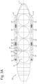
- Fig. 1 shows a high-level schematic of the power generating system of a floating independent power plant (FIPP).
- the FIPP is shown to comprise manifolds 31, LNG tanks 30, a regasification unit 40, a boiler 41, a propulsion unit 42, a power generation module 50 with a power generator set 51 and a cooling system 52, and an export gantry 59.
- the manifolds 31 serve as an inlet to the LNG tanks 30 and are adapted for loading LNG via marine loading hoses from LNG carriers which more alongside the FIPP.
- the regasification unit 40 is with an inlet connected to an outlet of the LNG tanks 30 and is adapted to regasify LNG to provide gas as fuel gas via a first outlet to the plurality of power generation sets 51 and via a second outlet to the boiler 41.
- the boiler 41 is with a first outlet connected to the propulsion unit 42 and with a second outlet connected to the plurality of power generation sets 51.
- the power generation sets 51 are each connected with an electric output to the export gantry 59 for exporting generated electricity to a power grid.
- Each of the power generation sets 51 is individually connected to a cooling system 52. Two embodiments of FIPP cooling systems are described in more detail with reference to Figs. 2C and 3C .
- the regasification unit comprises at least one centrifugal type fuel gas compressor (not shown) to compress boil-off gas from the LNG tanks 30 to a required fuel gas pressure for the gas engines.
- the at least one fuel gas compressor discharges pressurised gas to at least one fuel gas after-cooler/heater (not shown), which regulates the final temperature of the fuel gas prior to feeding the gas engines.
- the regasification unit further comprises at least one steam heated fuel gas vaporiser (not shown), adapted to produce from the LNG additional fuel gas which is required on top of the boil-off gas and suitable for direct supply to the gas engines. Pressurised LNG is introduced from the LNG tanks 30 and the boil-off gas is combined with the fuel gas downstream of the after-cooler/heater.
- Each power generator set 51 comprises at least one gas engine and an electric power generator (both not shown), wherein the gas engine(s) will deliver mechanical power to the electric power generator(s) for the production of electricity.
- the gas at fuel gas power is lead from the regasification unit to at least one of the plurality of power generation modules 50 into the power generator set 51 thereof.
- the generated electricity from the at least one power generator set 51 is generated at 15 kV and raised up to 132 kV export voltage, metered and subsequently supplied to the onshore grid through the export gantry 59.
- the export voltage can be set to specific project needs.
- the boiler 41 is running in order to supply steam for local power generation and LNG vaporisation.
- a boil-off gas system which is already present in the original LNG carrier is used for supplying gas to the boiler 41.
- the FIPP is self-propelled with a high pressure steam system as propulsion unit.
- the boiler 41 burns marine gas oil and/or gas depending on the LNG storage on board. All power generator units are shut-down during sailing.
- the required electricity for supporting the FIPP sailing is generated by a steam turbo generator and/or diesel generator, which is already present in the original LNG carrier from which the FIPP is converted and which is part of the aforementioned propulsion unit 42.
- a steam turbo generator is used, a secondary function of the boiler comprises continuous LNG gas burning, so that no diesel oil consumption is required.
- Figs. 2A and 2B respectively show a schematic top view and cross-sectional view of an embodiment of a FIPP, with a detailed schematic of the cooling system thereof shown in Fig. 2C .
- the FIPP is a vessel, with four Moss type LNG tanks 30, having a sponson 10, 20 on both sides of the hull 1.
- the sponsons 10, 20 extend over the full length of a cargo section of the hull 1 and are constructed to house the power generation modules 50 with the gas engine driven power generator sets 51 and their supporting systems.
- the sponsons 10, 20 are both subdivided into six equal length sections forming twelve compartments in total. In each of the compartments of one of the sponsons 20 a single power generator set 51 is installed.
- the compartments with the power generator sets 51 can be manufactured and pre-commissioned separately as power generation modules 50 and installed into the sponsons in a near-complete state.
- Four of the compartments of the other of the sponsons are each formed by a single power generation module 50, while the two compartments in the middle of the ship under the LNG transfer station have a seawater cooling system 60 installed.
- Air inlets 54 and outlets are created in the upper side of each of the power generation module 50 compartments. These inlets 54 and outlets are located as far apart as possible on opposite sides of each compartment to maximise air flow there through. The outlets of two neighbouring compartments are combined into a single exhaust funnel 55 to minimise the number of structures on the upper deck of the sponsons 10, 20.
- the structures of the sponsons 10, 20 have the same frame distances as the original LNG carrier's hull 1 in order to guarantee continuation of the original LNG carrier's hull structure inside the sponsons for optimal load transfer in the structure.
- the lower part of each of the sponsons 10, 20 is integrated at the location of the former bilge keel at mid-ship.
- the height of the sponsons 10, 20 is continuous between the fore and aft ends, such that the upper sides of both sponsons 10, 20 is aligned with the upper deck of the hull 1.
- the shape of the hull 1 towards the ends thereof dictates a widening of the sponsons 10, 20 to maintain a proper connection between said sponsons 10, 20 and the hull 1.
- the sponsons 10, 20 are slightly tapered on both ends thereof to reduce the drag during sailing.
- a pipe rack 58 is created on the upper deck to transport fuel gas, cooling water and cabling across the vessel.
- the pipe rack 58 is installed on the longitudinal sides of the deck of the original LNG carrier.
- the cooling system 52' in this embodiment is based on a seawater cooling system 60.
- the cooling system 52' comprises a dedicated fresh water circulation loop 68 for each of the power generation modules 50 and the regasification unit 40, comprising at least one pump 51c for circulating the fresh water therein, and the seawater cooling system 60 located in the sponson 10, which comprises a sea chest 61, seawater lift pumps 62 and heat exchanger tanks 65.
- Each of the fresh water circulation loops 68 runs between the power generation module 50 or regasification unit 40, where the fresh water absorbs heat from the engines and auxiliaries, to the heat exchanger tanks, where the fresh water releases heat to the seawater therein, prior to being cycled back to the power generation module 50 or regasification unit 40.
- the sea chest 61 is located in the bottom of the sponson 10, below sea-level, and adapted to take in and store cold seawater.
- the seawater lift pumps 62 take 'cold' seawater as cooling medium from the sea chest 61 and pump it via inlets 63 into the heat exchanger tanks 65, where the cold seawater exchanges heat with the fresh water from the fresh water circulation loops 68 running there through. Heated seawater is expelled overboard the vessel via outlet channels 64, positioned at an upper side of the heat exchanger tanks 65.
- Figs. 3A and 3B respectively show a schematic top view and cross-sectional view of an alternative embodiment of a FIPP, with a detailed schematic of the cooling system thereof shown in Fig. 3C .
- the embodiment of Fig. 3A-3C is similar to the one shown in Fig. 2A-2C , except that in the embodiment of Fig. 3A-3C both sponsons 10', 20' are subdivided into five equal length sections forming compartments, which have a single power generator set 51 installed therein.
- this embodiment's cooling system 52" is an air cooling system, as shown in Fig. 3C .
- the air cooling system 52" comprises a dedicated fresh water circulation loop 68' for each of the power generation modules 50', comprising a pump 5 1c for circulation of the fresh water therein, and a heat exchanger 69' in the form of air cooler cells 65' provided with fans 67 creating a forced ambient air flow.
- the fresh water in the fresh water circulation loop 68' is heated up by the gas engine and auxiliary equipment in the power generation module 50' and pumped to the air cooling cells, which are located outside the compartment on or above deck level, to exchange heat with the ambient air flow prior to being cycled back to the power generation module 50'.
- the air cooling cells are for example arranged at deck level, which may extend over the sponsons, or alternatively on a higher level, for example mounted on a rack above deck level.
- Each power generation module 50' is connected via the dedicated fresh water circulation loop 68' to a dedicated heat exchanger 69', which is installed above the sponson 10', 20'.
- the dedicated heat exchanger 69' may take almost full width of the sponson, in some embodiments.
- each heat exchanger has five air cooler cells 65'.
- the fresh water is preferably lead over or through the air cooler cells in a thin flow layer, for example through the use of a finned tube bundle, in order to create a large heat exchange area and enhance heat transfer.
- the fans 67 provide additional (forced) airflow over the surface of the air cooler cells 65', further enhancing heat transfer and thus improving the cooling capacity of the cooling system.
- the air cooling system 52" is shown to replace the seawater cooling system of Fig. 2 , but alternatively it may be desirable to use the cooling system of Fig. 3C in addition to the seawater based cooling system of Fig. 2C .
Landscapes
- Engineering & Computer Science (AREA)
- Architecture (AREA)
- Civil Engineering (AREA)
- Structural Engineering (AREA)
- Chemical & Material Sciences (AREA)
- Combustion & Propulsion (AREA)
- Mechanical Engineering (AREA)
- Ocean & Marine Engineering (AREA)
- Engine Equipment That Uses Special Cycles (AREA)
Claims (14)
- Centrale électrique indépendante flottante, FIPP, (100 ; 200) comprenant un transporteur de gaz naturel liquéfié, GNL, de type Moss converti avec une coque (1) et une pluralité de réservoirs de stockage de GNL (30) agencés à l'intérieur de la coque, dans laquelle la centrale électrique indépendante flottante comprend :- une unité de regazéification (40), reliée à l'aide d'une entrée à la pluralité de réservoirs de stockage de GNL (30), pour une regazéification de GNL stocké ;- une pluralité de modules de production d'énergie (50 ; 50') comprenant des ensembles de générateurs d'énergie (51), et
étant pourvue d'une entrée reliée à une sortie de l'unité de regazéification (40) pour recevoir du gaz combustible et adaptée pour générer de l'électricité en utilisant le gaz combustible reçu ;- un équipement de refroidissement (52 ; 52'; 52"), couplé à la pluralité de modules de production d'énergie (50 ; 50') et agencé pour refroidir la pluralité de modules de production d'énergie ; et- un flotteur (10, 20 ; 10', 20') de part et d'autre de la coque (1),caractérisée en ce que
chaque flotteur (10, 20 ; 10'; 20') est subdivisé en une pluralité de compartiments (50, 60 ; 50') de taille sensiblement égale le long d'une direction longitudinale du flotteur (10, 20 ; 10', 20') montés de manière fixe de part et d'autre de la coque (1) et agencées pour recevoir la pluralité de modules de générateur d'énergie (50 ; 50'), chaque compartiment contenant un module de générateur d'énergie (51), dans laquelle chacun de la pluralité de modules de générateur d'énergie (50 ; 50') forme l'un de la pluralité de compartiments (50, 60 ; 50'), et dans laquelle chacun des compartiments comprenant un ensemble de générateurs de d'énergie (51) est pourvu d'un tuyau d'échappement (55) et d'une entrée d'air (54) dans un côté supérieur, dans laquelle les compartiments sont agencés de telle sorte que des modules de production d'énergie voisins (50 ; 50') sont en image miroir autour de leur paroi voisine, le tuyau d'échappement (55) et l'entrée d'air (54) étant situées sur des côtés longitudinalement opposés du compartiment et les tuyaux d'échappement (55) de compartiments voisins étant combinés en un entonnoir de tuyaux d'échappement. - Centrale électrique indépendante flottante (100 ; 200) selon la revendication 1, comprenant au moins dix modules de générateur d'énergie (50 ; 50') et dans laquelle chaque flotteur (10, 20 ; 10', 20') est subdivisée en au moins cinq compartiments le long de la longueur du flotteur (10, 20 ; 10', 20').
- Centrale électrique indépendante flottant (100 ; 200) selon l'une quelconque des revendications précédentes, dans laquelle la centrale électrique flottante indépendante comprend un générateur de turbine à vapeur et/ou un ou plusieurs générateurs diesel pour supporter la navigation de telle sorte que la centrale électrique indépendante flottante est automotrice pendant un déploiement.
- Centrale électrique indépendante flottante (200) selon l'une quelconque des revendications précédentes, dans laquelle l'équipement de refroidissement (52") comprend une boucle de circulation d'eau douce fermée (68') pour chaque ensemble de générateurs d'énergie (51) et un échangeur de chaleur (69') installé au-dessus de chacun des flotteurs (10', 20') et/ou sur le pont principal en contact direct avec l'environnement extérieur, avec chacune des boucles de circulation d'eau douce fermée s'étendant entre l'un des ensembles de production d'énergie et l'échangeur de chaleur, l'échangeur de chaleur étant un échangeur de chaleur à écoulement d'air.
- Centrale électrique indépendante flottante (200) selon la revendication 4, dans laquelle l'échangeur de chaleur à écoulement d'air (69') comprend une pluralité de cellules refroidies par air (65').
- Centrale électrique indépendante flottante (200) selon la revendication 5, dans laquelle l'échangeur de chaleur à écoulement d'air (69') comprend en outre au moins un ventilateur (67) pour fournir un écoulement d'air forcé en tant que milieu de refroidissement local.
- Centrale électrique indépendante flottante (200) selon la revendication 5 ou 6, dans laquelle chaque ensemble de générateurs d'énergie (51) est pourvu d'au moins une cellule refroidie par air dédiée (65').
- Centrale électrique flottante indépendante (100) selon l'une quelconque des revendications 1 à 3, dans laquelle l'équipement de refroidissement (52') comprend une boucle de circulation d'eau douce fermée (68) pour chaque ensemble de générateurs d'énergie (51) et un échangeur de chaleur (65) installé dans la coque (1) ou l'un des flotteurs (10 ;20), chacune des boucles d'eau douce fermée (68) s'étendant entre un certain des ensembles de générateurs d'énergie (51) et l'échangeur de chaleur pour échanger de la chaleur avec celui-ci et dans laquelle l'échangeur de chaleur (65) est relié à une entrée (61) à au moins un réservoir de stockage d'eau de mer froide (61) pour recevoir de l'eau de mer en tant que milieu de refroidissement dans l'échangeur de chaleur, et à une sortie (64) s'étendant à travers la coque (1) pour évacuer l'eau de mer chauffée en pleine mer, dans laquelle le réservoir de stockage d'eau de mer froide (61) est situé dans un ou plusieurs compartiments (60) des flotteurs (10, 20) ne contenant pas d'ensemble de générateurs d'énergie et le réservoir de stockage d'eau de mer froide est pourvu d'une liaison à un système de levage d'eau de mer (62).
- Centrale électrique flottante indépendante (100 ; 200) selon l'une quelconque des revendications 4 à 8, dans laquelle chacune des boucles de circulation d'eau douce fermées (68, 68') comprend une pompe (51c) pour pomper l'eau douce à travers la boucle de circulation d'eau douce fermée, laquelle pompe est entraînée par l'ensemble de générateurs d'énergie (51).
- Centrale électrique indépendante flottante (100 ; 200) selon l'une quelconque des revendications 4 à 9, dans laquelle l'unité de regazéification (40) est pourvue d'une boucle de circulation d'eau douce fermée qui s'étend entre l'unité de regazéification et l'échangeur de chaleur.
- Centrale électrique indépendante flottante (100 ; 200) selon l'une quelconque des revendications précédentes, dans laquelle la centrale électrique indépendante flottante comprend un portique d'exportation (59) destiné à être relié à un réseau terrestre pour lui fournir l'électricité générée.
- Procédé de transformation d'un transporteur de GNL de type Moss en une centrale électrique flottante indépendante (100 ; 200), comprenant les étapes consistant àretirer les quilles antiroulis existantes de part et d'autre de la coque (1) ;fournir une pluralité de modules de générateur d'énergie (50 ; 50') comprenant chacun un ensemble de générateurs d'énergie (51), une entrée d'air (54) et une sortie (55), dans laquelle l'entrée d'air et la sortie sont situées sur des côtés opposés du module (50 ; 50') ;fixer deux flotteurs (10, 20 ; 10', 20') de part et d'autre de la coque (1), en intégrant une partie inférieure de chaque flotteur au niveau de l'emplacement de la quille antiroulis ;assembler la pluralité de modules de générateur d'énergie (50 ; 50') dans une partie supérieure des deux flotteurs (10, 20 ; 10', 20'), de telle sorte que chacun des deux flotteurs soit subdivisé en une pluralité de compartiments de taille sensiblement égale (50, 60 ; 50') le long d'une direction longitudinale, et de telle sorte que des modules de générateur d'énergie voisins (50 ; 50') soient en image miroir autour de leur paroi voisine, et combiner les sorties (55) de modules de générateur d'énergie voisins dans un entonnoir de tuyaux d'échappement ;fournir une unité de regazéification (40) pour créer du gaz combustible à partir de GNL, relier ladite unité de regazéification avec une entrée vers les réservoirs de GNL et avec une sortie pour fournir le gaz combustible créé à la pluralité de modules de générateur d'énergie (50 ; 50').
- Procédé selon la revendication 12, comprenant en outre la fourniture à chacun des modules de générateur d'énergie (50') d'au moins une cellule refroidie par air (65') sur un côté supérieur formant un pont du flotteur et d'une boucle de circulation d'eau douce fermée (68') s'étendant entre l'ensemble de générateurs d'énergie et ladite au moins une cellule refroidie par air.
- Procédé selon la revendication 13, comprenant en outre la fourniture d'au moins un ventilateur (67) sur un côté supérieur de chacun des modules de générateur d'énergie (50 ; 50') pour créer un écoulement d'air forcé qui est dirigé au-dessus de la au moins une cellule refroidie par air (65').
Applications Claiming Priority (2)
| Application Number | Priority Date | Filing Date | Title |
|---|---|---|---|
| EP20176328 | 2020-05-25 | ||
| PCT/EP2021/063883 WO2021239724A1 (fr) | 2020-05-25 | 2021-05-25 | Centrale électrique indépendante flottante et procédé de conversion d'un support gnl en cette dernière |
Publications (2)
| Publication Number | Publication Date |
|---|---|
| EP4157708A1 EP4157708A1 (fr) | 2023-04-05 |
| EP4157708B1 true EP4157708B1 (fr) | 2025-07-02 |
Family
ID=70804589
Family Applications (1)
| Application Number | Title | Priority Date | Filing Date |
|---|---|---|---|
| EP21730806.3A Active EP4157708B1 (fr) | 2020-05-25 | 2021-05-25 | Centrale électrique flottante indépendante et procédé de conversion d'un transporteur de gnl en une |
Country Status (2)
| Country | Link |
|---|---|
| EP (1) | EP4157708B1 (fr) |
| WO (1) | WO2021239724A1 (fr) |
Families Citing this family (1)
| Publication number | Priority date | Publication date | Assignee | Title |
|---|---|---|---|---|
| WO2023102595A1 (fr) * | 2021-12-07 | 2023-06-15 | Charlie Six Pty Ltd | Navire à gaz liquéfié |
Family Cites Families (4)
| Publication number | Priority date | Publication date | Assignee | Title |
|---|---|---|---|---|
| NO331660B1 (no) * | 2008-11-19 | 2012-02-20 | Moss Maritime As | Anordning for flytende produksjon av LNG og fremgangsmate for a konvertere et LNG-skip til en slik anordning |
| AU2011335362B2 (en) | 2010-11-30 | 2016-08-18 | Single Buoy Moorings Inc. | Floating LNG plant |
| WO2018144024A1 (fr) * | 2017-02-05 | 2018-08-09 | Pcore Energy Llc | Regazéification de gaz naturel liquéfié et système d'optimisation de chaleur de production d'énergie |
| CA3089431A1 (fr) * | 2018-01-29 | 2019-08-01 | Single Buoy Moorings Inc. | Centrale electrique en mer |
-
2021
- 2021-05-25 EP EP21730806.3A patent/EP4157708B1/fr active Active
- 2021-05-25 WO PCT/EP2021/063883 patent/WO2021239724A1/fr not_active Ceased
Also Published As
| Publication number | Publication date |
|---|---|
| EP4157708A1 (fr) | 2023-04-05 |
| WO2021239724A1 (fr) | 2021-12-02 |
Similar Documents
| Publication | Publication Date | Title |
|---|---|---|
| EP3412555B1 (fr) | Navire comprenant un système de re-vaporisation de gaz | |
| US20140338371A1 (en) | Method and apparatus for the regasification of lng onboard a carrier | |
| EP3746643B1 (fr) | Centrale électrique offshore | |
| KR101929435B1 (ko) | 부체식 액화 탄화수소 가스 플랜트의 제조 방법 | |
| US20120324910A1 (en) | Articulated Tug and Barge Arrangement for LNG Storage, Transportation and Regasification | |
| KR102384294B1 (ko) | 가스 재기화 시스템 및 이를 포함하는 선박 | |
| WO2018144024A1 (fr) | Regazéification de gaz naturel liquéfié et système d'optimisation de chaleur de production d'énergie | |
| US20190032852A1 (en) | Ship including gas re-vaporizing system | |
| EP4157708B1 (fr) | Centrale électrique flottante indépendante et procédé de conversion d'un transporteur de gnl en une | |
| US11628916B1 (en) | Integrated system for producing electrical power for ship propulsion using modularized fuel storage and fuel containers | |
| EP4401174A1 (fr) | Un navire équipé d'une centrale électrique à pile à combustible | |
| KR102054582B1 (ko) | 가스 재기화 시스템 및 이를 포함하는 선박 | |
| KR102054583B1 (ko) | 가스 재기화 시스템 및 이를 포함하는 선박 | |
| KR20230019513A (ko) | 풍력 발전기 설치 선박의 액화가스 운용 시스템 | |
| WO2018139997A1 (fr) | Unité flottante de stockage, de regazéification et de génération de gaz naturel liquéfié | |
| KR20220105536A (ko) | 전기추진 시스템 및 이를 포함하는 선박 | |
| KR102594024B1 (ko) | 선박의 연료공급시스템 및 방법 | |
| KR20240025519A (ko) | 수역에 배치되도록 의도된 설비에 의해 전기를 생산하기 위한 방법 | |
| KR102623372B1 (ko) | 가스연료 추진 차량 운반선 | |
| KR102623378B1 (ko) | 가스연료 추진 차량 운반선 | |
| KR20240173425A (ko) | 부유식 배터리 충전소 | |
| KR102057779B1 (ko) | 가스 재기화 시스템 및 이를 포함하는 선박 | |
| KR20230019343A (ko) | 풍력 발전기 설치 선박 | |
| CN117657414A (zh) | 一种模块化小型堆动力系统及船舶 | |
| KR20230019341A (ko) | 풍력 발전기 설치 선박 |
Legal Events
| Date | Code | Title | Description |
|---|---|---|---|
| STAA | Information on the status of an ep patent application or granted ep patent |
Free format text: STATUS: UNKNOWN |
|
| STAA | Information on the status of an ep patent application or granted ep patent |
Free format text: STATUS: THE INTERNATIONAL PUBLICATION HAS BEEN MADE |
|
| PUAI | Public reference made under article 153(3) epc to a published international application that has entered the european phase |
Free format text: ORIGINAL CODE: 0009012 |
|
| STAA | Information on the status of an ep patent application or granted ep patent |
Free format text: STATUS: REQUEST FOR EXAMINATION WAS MADE |
|
| 17P | Request for examination filed |
Effective date: 20221209 |
|
| AK | Designated contracting states |
Kind code of ref document: A1 Designated state(s): AL AT BE BG CH CY CZ DE DK EE ES FI FR GB GR HR HU IE IS IT LI LT LU LV MC MK MT NL NO PL PT RO RS SE SI SK SM TR |
|
| DAV | Request for validation of the european patent (deleted) | ||
| DAX | Request for extension of the european patent (deleted) | ||
| STAA | Information on the status of an ep patent application or granted ep patent |
Free format text: STATUS: EXAMINATION IS IN PROGRESS |
|
| 17Q | First examination report despatched |
Effective date: 20240403 |
|
| GRAP | Despatch of communication of intention to grant a patent |
Free format text: ORIGINAL CODE: EPIDOSNIGR1 |
|
| STAA | Information on the status of an ep patent application or granted ep patent |
Free format text: STATUS: GRANT OF PATENT IS INTENDED |
|
| INTG | Intention to grant announced |
Effective date: 20250122 |
|
| GRAS | Grant fee paid |
Free format text: ORIGINAL CODE: EPIDOSNIGR3 |
|
| GRAA | (expected) grant |
Free format text: ORIGINAL CODE: 0009210 |
|
| STAA | Information on the status of an ep patent application or granted ep patent |
Free format text: STATUS: THE PATENT HAS BEEN GRANTED |
|
| AK | Designated contracting states |
Kind code of ref document: B1 Designated state(s): AL AT BE BG CH CY CZ DE DK EE ES FI FR GB GR HR HU IE IS IT LI LT LU LV MC MK MT NL NO PL PT RO RS SE SI SK SM TR |
|
| REG | Reference to a national code |
Ref country code: GB Ref legal event code: FG4D |
|
| REG | Reference to a national code |
Ref country code: CH Ref legal event code: EP |
|
| REG | Reference to a national code |
Ref country code: DE Ref legal event code: R096 Ref document number: 602021033364 Country of ref document: DE |
|
| REG | Reference to a national code |
Ref country code: IE Ref legal event code: FG4D |
|
| REG | Reference to a national code |
Ref country code: NL Ref legal event code: FP |
|
| PG25 | Lapsed in a contracting state [announced via postgrant information from national office to epo] |
Ref country code: PT Free format text: LAPSE BECAUSE OF FAILURE TO SUBMIT A TRANSLATION OF THE DESCRIPTION OR TO PAY THE FEE WITHIN THE PRESCRIBED TIME-LIMIT Effective date: 20251103 |
|
| REG | Reference to a national code |
Ref country code: AT Ref legal event code: MK05 Ref document number: 1808964 Country of ref document: AT Kind code of ref document: T Effective date: 20250702 |
|
| PG25 | Lapsed in a contracting state [announced via postgrant information from national office to epo] |
Ref country code: IS Free format text: LAPSE BECAUSE OF FAILURE TO SUBMIT A TRANSLATION OF THE DESCRIPTION OR TO PAY THE FEE WITHIN THE PRESCRIBED TIME-LIMIT Effective date: 20251102 |
|
| REG | Reference to a national code |
Ref country code: LT Ref legal event code: MG9D |
|
| PG25 | Lapsed in a contracting state [announced via postgrant information from national office to epo] |
Ref country code: AT Free format text: LAPSE BECAUSE OF FAILURE TO SUBMIT A TRANSLATION OF THE DESCRIPTION OR TO PAY THE FEE WITHIN THE PRESCRIBED TIME-LIMIT Effective date: 20250702 |
|
| PG25 | Lapsed in a contracting state [announced via postgrant information from national office to epo] |
Ref country code: FI Free format text: LAPSE BECAUSE OF FAILURE TO SUBMIT A TRANSLATION OF THE DESCRIPTION OR TO PAY THE FEE WITHIN THE PRESCRIBED TIME-LIMIT Effective date: 20250702 |
|
| PG25 | Lapsed in a contracting state [announced via postgrant information from national office to epo] |
Ref country code: HR Free format text: LAPSE BECAUSE OF FAILURE TO SUBMIT A TRANSLATION OF THE DESCRIPTION OR TO PAY THE FEE WITHIN THE PRESCRIBED TIME-LIMIT Effective date: 20250702 |
|
| PG25 | Lapsed in a contracting state [announced via postgrant information from national office to epo] |
Ref country code: GR Free format text: LAPSE BECAUSE OF FAILURE TO SUBMIT A TRANSLATION OF THE DESCRIPTION OR TO PAY THE FEE WITHIN THE PRESCRIBED TIME-LIMIT Effective date: 20251003 |
|
| PG25 | Lapsed in a contracting state [announced via postgrant information from national office to epo] |
Ref country code: SE Free format text: LAPSE BECAUSE OF FAILURE TO SUBMIT A TRANSLATION OF THE DESCRIPTION OR TO PAY THE FEE WITHIN THE PRESCRIBED TIME-LIMIT Effective date: 20250702 Ref country code: CZ Free format text: LAPSE BECAUSE OF FAILURE TO SUBMIT A TRANSLATION OF THE DESCRIPTION OR TO PAY THE FEE WITHIN THE PRESCRIBED TIME-LIMIT Effective date: 20250702 |
|
| PG25 | Lapsed in a contracting state [announced via postgrant information from national office to epo] |
Ref country code: LV Free format text: LAPSE BECAUSE OF FAILURE TO SUBMIT A TRANSLATION OF THE DESCRIPTION OR TO PAY THE FEE WITHIN THE PRESCRIBED TIME-LIMIT Effective date: 20250702 |
|
| PG25 | Lapsed in a contracting state [announced via postgrant information from national office to epo] |
Ref country code: PL Free format text: LAPSE BECAUSE OF FAILURE TO SUBMIT A TRANSLATION OF THE DESCRIPTION OR TO PAY THE FEE WITHIN THE PRESCRIBED TIME-LIMIT Effective date: 20250702 Ref country code: BG Free format text: LAPSE BECAUSE OF FAILURE TO SUBMIT A TRANSLATION OF THE DESCRIPTION OR TO PAY THE FEE WITHIN THE PRESCRIBED TIME-LIMIT Effective date: 20250702 |
|
| PG25 | Lapsed in a contracting state [announced via postgrant information from national office to epo] |
Ref country code: RS Free format text: LAPSE BECAUSE OF FAILURE TO SUBMIT A TRANSLATION OF THE DESCRIPTION OR TO PAY THE FEE WITHIN THE PRESCRIBED TIME-LIMIT Effective date: 20251002 |
|
| PG25 | Lapsed in a contracting state [announced via postgrant information from national office to epo] |
Ref country code: ES Free format text: LAPSE BECAUSE OF FAILURE TO SUBMIT A TRANSLATION OF THE DESCRIPTION OR TO PAY THE FEE WITHIN THE PRESCRIBED TIME-LIMIT Effective date: 20250702 |
|
| PG25 | Lapsed in a contracting state [announced via postgrant information from national office to epo] |
Ref country code: SM Free format text: LAPSE BECAUSE OF FAILURE TO SUBMIT A TRANSLATION OF THE DESCRIPTION OR TO PAY THE FEE WITHIN THE PRESCRIBED TIME-LIMIT Effective date: 20250702 |
|
| PG25 | Lapsed in a contracting state [announced via postgrant information from national office to epo] |
Ref country code: DK Free format text: LAPSE BECAUSE OF FAILURE TO SUBMIT A TRANSLATION OF THE DESCRIPTION OR TO PAY THE FEE WITHIN THE PRESCRIBED TIME-LIMIT Effective date: 20250702 |
|
| PG25 | Lapsed in a contracting state [announced via postgrant information from national office to epo] |
Ref country code: SK Free format text: LAPSE BECAUSE OF FAILURE TO SUBMIT A TRANSLATION OF THE DESCRIPTION OR TO PAY THE FEE WITHIN THE PRESCRIBED TIME-LIMIT Effective date: 20250702 Ref country code: EE Free format text: LAPSE BECAUSE OF FAILURE TO SUBMIT A TRANSLATION OF THE DESCRIPTION OR TO PAY THE FEE WITHIN THE PRESCRIBED TIME-LIMIT Effective date: 20250702 |