EP4158131B1 - Ancrage de montage de toit antichute - Google Patents
Ancrage de montage de toit antichute Download PDFInfo
- Publication number
- EP4158131B1 EP4158131B1 EP22818160.8A EP22818160A EP4158131B1 EP 4158131 B1 EP4158131 B1 EP 4158131B1 EP 22818160 A EP22818160 A EP 22818160A EP 4158131 B1 EP4158131 B1 EP 4158131B1
- Authority
- EP
- European Patent Office
- Prior art keywords
- anchor
- mounting plate
- central portion
- channel
- raised central
- Prior art date
- Legal status (The legal status is an assumption and is not a legal conclusion. Google has not performed a legal analysis and makes no representation as to the accuracy of the status listed.)
- Active
Links
Images


Classifications
-
- A—HUMAN NECESSITIES
- A62—LIFE-SAVING; FIRE-FIGHTING
- A62B—DEVICES, APPARATUS OR METHODS FOR LIFE-SAVING
- A62B35/00—Safety belts or body harnesses; Similar equipment for limiting displacement of the human body, especially in case of sudden changes of motion
- A62B35/0006—Harnesses; Accessories therefor
- A62B35/0025—Details and accessories
- A62B35/0037—Attachments for lifelines and lanyards
-
- A—HUMAN NECESSITIES
- A62—LIFE-SAVING; FIRE-FIGHTING
- A62B—DEVICES, APPARATUS OR METHODS FOR LIFE-SAVING
- A62B35/00—Safety belts or body harnesses; Similar equipment for limiting displacement of the human body, especially in case of sudden changes of motion
- A62B35/0043—Lifelines, lanyards, and anchors therefore
- A62B35/0068—Anchors
-
- A—HUMAN NECESSITIES
- A62—LIFE-SAVING; FIRE-FIGHTING
- A62B—DEVICES, APPARATUS OR METHODS FOR LIFE-SAVING
- A62B35/00—Safety belts or body harnesses; Similar equipment for limiting displacement of the human body, especially in case of sudden changes of motion
- A62B35/04—Safety belts or body harnesses; Similar equipment for limiting displacement of the human body, especially in case of sudden changes of motion incorporating energy absorbing means
-
- E—FIXED CONSTRUCTIONS
- E04—BUILDING
- E04G—SCAFFOLDING; FORMS; SHUTTERING; BUILDING IMPLEMENTS OR AIDS, OR THEIR USE; HANDLING BUILDING MATERIALS ON THE SITE; REPAIRING, BREAKING-UP OR OTHER WORK ON EXISTING BUILDINGS
- E04G21/00—Preparing, conveying, or working-up building materials or building elements in situ; Other devices or measures for constructional work
- E04G21/32—Safety or protective measures for persons during the construction of buildings
- E04G21/3204—Safety or protective measures for persons during the construction of buildings against falling down
- E04G21/3214—Means for working on roofs
-
- E—FIXED CONSTRUCTIONS
- E04—BUILDING
- E04G—SCAFFOLDING; FORMS; SHUTTERING; BUILDING IMPLEMENTS OR AIDS, OR THEIR USE; HANDLING BUILDING MATERIALS ON THE SITE; REPAIRING, BREAKING-UP OR OTHER WORK ON EXISTING BUILDINGS
- E04G21/00—Preparing, conveying, or working-up building materials or building elements in situ; Other devices or measures for constructional work
- E04G21/32—Safety or protective measures for persons during the construction of buildings
- E04G21/3261—Safety-nets; Safety mattresses; Arrangements on buildings for connecting safety-lines
- E04G21/3276—Arrangements on buildings for connecting safety-lines
- E04G21/328—Arrangements on buildings for connecting safety-lines fastened to the roof covering or insulation
-
- E—FIXED CONSTRUCTIONS
- E04—BUILDING
- E04G—SCAFFOLDING; FORMS; SHUTTERING; BUILDING IMPLEMENTS OR AIDS, OR THEIR USE; HANDLING BUILDING MATERIALS ON THE SITE; REPAIRING, BREAKING-UP OR OTHER WORK ON EXISTING BUILDINGS
- E04G21/00—Preparing, conveying, or working-up building materials or building elements in situ; Other devices or measures for constructional work
- E04G21/32—Safety or protective measures for persons during the construction of buildings
- E04G21/3261—Safety-nets; Safety mattresses; Arrangements on buildings for connecting safety-lines
- E04G21/3276—Arrangements on buildings for connecting safety-lines
- E04G21/329—Arrangements on buildings for connecting safety-lines with measures for dampening the fall
-
- Y—GENERAL TAGGING OF NEW TECHNOLOGICAL DEVELOPMENTS; GENERAL TAGGING OF CROSS-SECTIONAL TECHNOLOGIES SPANNING OVER SEVERAL SECTIONS OF THE IPC; TECHNICAL SUBJECTS COVERED BY FORMER USPC CROSS-REFERENCE ART COLLECTIONS [XRACs] AND DIGESTS
- Y02—TECHNOLOGIES OR APPLICATIONS FOR MITIGATION OR ADAPTATION AGAINST CLIMATE CHANGE
- Y02E—REDUCTION OF GREENHOUSE GAS [GHG] EMISSIONS, RELATED TO ENERGY GENERATION, TRANSMISSION OR DISTRIBUTION
- Y02E10/00—Energy generation through renewable energy sources
- Y02E10/40—Solar thermal energy, e.g. solar towers
- Y02E10/47—Mountings or tracking
Definitions
- This invention relates generally to a fall arrest roof mount anchor.
- Fall arrest roof mount anchors are used for industry applications involving high fall risk, to secure harnessed construction and maintenance personnel working at heights on buildings and structures.
- These height safety anchors may comprise a formed aluminium extrusion mounting plate which is permanently affixed to a roof profile surface, and which exposes a swivel eye anchor point for attachment of a carabiner, lanyard and other conventional harness hardware.
- An example of a height safety anchor known in the art can be found in EP 2961898B1 .
- a fall arrest roof mount anchor ideally suited to construction and maintenance personnel working at heights, utilising a harness and lanyard fall protection equipment.
- a first aspect of the invention is set out in independent claim 1.
- Optional features are as disclosed in dependent claims 2 to 17.
- the uniform cross-section and the under channel enhance shear force resilience and flexural stiffness to lateral applied strain, especially when applied along a longitudinal axis of the channel.
- the under channel coincides with the swivel eye anchor point, thereby maximising the shear force resilience conferred by the under channel at the point of fall arrest loading.
- the present roof mount anchor may be structurally resilient yet lightweight.
- an aluminium extrusion embodiment of the present anchor may be rated to 15kN yet only weigh 800g.
- the under channel is configured to conveniently capture a locknut of an anchor bolt whilst yet allowing a distal end of the anchor bolt to extend therebetween.
- connection of the side portions of the mounting plate across two roof profile ribs dissipates the load over a greater area and enhances fall arrest rated performance. Furthermore, installation across two ribs prevents or reduces potential for roof sheet delamination, which could occur when a roof mount is fixed with rivets to one roof sheet only.
- This unique energy deforming matrix arrangement allows the mounting plate to flex around the swivel eye anchor point, thereby dissipating energy in a shock load situation without compromising the structural integrity of the remainder of the mounting plate.
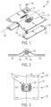
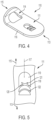
- the roof mount anchor 100 may comprise mounting pads 126 preferably of rubber material, which engage under each roof attachment side 104 of the mounting plate 101.
- the mounting pads 126 may comprise a plurality of fastener holes 127 which collocate with the rivet fastener holes 124 of the mounting plate 101.
- the mounting plate 101 may further splay longitudinally along the horizontal axis 102 towards both ends thereof.
- the roof mount anchor 100 may further comprise a lanyard connector 110 attached to an apex of the raised central portion 103.
- the lanyard connector 110 may define an anchor connection aperture 111 for swivel engagement by the anchor bolt 108 at a proximal end 113 thereof.
- the mounting plate 101 accordingly comprises a anchor point connection hole 112, preferably a central anchor point connection hole 112, for the anchor bolt 108.
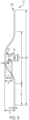
- the anchor connection aperture 111 may be elongate along a strain absorbing axis 117 through the proximal end 113 and distal end 115 of the lanyard connector 110.
- the lanyard connector 110 may have an integrally formed primary frail web 118 across the strain absorbing axis 117.
- the anchor connection aperture 111 may define a profile open an anchor bolt accommodation portion 119 which accommodates the anchor bolt 108 therethrough.
- the primary frail web 118 is preferably curved across the anchor connection aperture 111.
- the primary frail web 118 is further preferably inversely orientated so that an apex 120 thereof bears oppositely against the anchor bolt 108. This arrangement is designed both to absorb energy and reduce shock impact on the user, whilst also providing visual indication of abnormal loading (such as in excess of 7 kN), which is useful when undertaking routine inspection of the fall arrest system
- the primary frail web 118 may have an integral seating profile 121 which supports the anchor bolt 108 centrally against the primary frail web apex 120.
- the seating profile 121 may have an opposite curvature to that of the primary frail web 118.
- the anchor connection aperture 111 may further comprise an integrally formed secondary frail web 122 across the strain absorbing axis 117.
- the secondary frail web 122 width may be narrower than the primary frail web 118 width, such as being approximately 1 mm as shown in Figure 10 .
- the mounting plate 101 may comprise a matrix 130 of elongate stress relief cut-outs 123 surrounding the swivel eye anchor point.
- Each stress relief cut-out 123 may arc concentrically around the swivel eye anchor point.
Landscapes
- Engineering & Computer Science (AREA)
- Architecture (AREA)
- Mechanical Engineering (AREA)
- Civil Engineering (AREA)
- Structural Engineering (AREA)
- Health & Medical Sciences (AREA)
- General Health & Medical Sciences (AREA)
- Business, Economics & Management (AREA)
- Emergency Management (AREA)
- Roof Covering Using Slabs Or Stiff Sheets (AREA)
- Emergency Lowering Means (AREA)
- Joining Of Building Structures In Genera (AREA)
Claims (17)
- Un ancrage de montage de toit antichute (100) comprenant une plaque de montage (101) ayant une section transversale uniforme définissant :une partie centrale surélevée (103) ; etdes parties latérales (104) pour la fixation au toit, et dans lequel :la partie centrale surélevée (103) comporte un point d'ancrage à œillet pivotant ; et la plaque de montage (101) comprend en outre des parties de paroi de canal (106) indépendantes de la partie centrale surélevée (103) et des parties latérales (104), les parties de paroi de canal (106) faisant saillie à partir d'une surface inférieure de la partie centrale surélevée (103), définissant ainsi un canal (105) s'étendant le long de la surface inférieure de la partie centrale surélevée (103) et coïncidant avec le point d'ancrage à œillet pivotant ;dans lequel le point d'ancrage comporte un trou (112) à travers une surface supérieure de la partie centrale surélevée (103) dans le canal (105) situé en dessous ;dans lequel l'ancrage de montage de toit antichute (100) comprend en outre un boulon d'ancrage (108) s'étendant à travers le trou (112) et dans lequel le canal (105) capture un contre-écrou (107) s'engageant avec ledit boulon d'ancrage (108) ; etcaractérisé en ce que les parties latérales parallèles intérieures du canal (105) sont espacées selon un diamètre minimum du contre-écrou (107) pour capturer de manière non rotative le contre-écrou (107).
- L'ancrage (100) selon la revendication 1, dans lequel les parties de paroi de canal (106) font saillie parallèlement les unes aux autres à partir de la surface inférieure de la partie centrale surélevée (103).
- L'ancrage (100) selon la revendication 1, dans lequel les parties de paroi de canal (106) définissent un espace entre elles pour permettre à une extrémité distale du boulon d'ancrage (108) de s'étendre à travers celles-ci lorsque le contre-écrou (107) est capturé par le canal (105).
- L'ancrage (100) selon la revendication 1, dans lequel la plaque de montage (101) comprend en outre des parties de bride s'étendant vers l'intérieur (109) à partir des extrémités distales respectives des parties de paroi de canal (106), et dans lequel les parties de bride s'étendant vers l'intérieur (109) supportent le contre-écrou (107) à l'intérieur du canal (105) tout en permettant à l'extrémité distale du boulon d'ancrage (108) de s'étendre entre elles.
- L'ancrage (100) selon la revendication 1, dans lequel la plaque de montage (101) comprend une matrice (130) de découpes de soulagement de contrainte allongée (123) entourant le point d'ancrage de l'œil pivotant, et dans laquelle les découpes de soulagement de contrainte (123) s'arc-boutent concentriquement autour du point d'ancrage de l'œil pivotant, et les extrémités des découpes de soulagement de contrainte radialement adjacentes (123) se chevauchent.
- L'ancrage (100) selon la revendication 5, dans lequel des paires opposées de découpes de soulagement de contrainte (123) sont disposées symétriquement autour du point d'ancrage de l'œillet pivotant.
- L'ancrage (100) selon la revendication 1, dans lequel la plaque de montage (101) se courbe en douceur entre la partie centrale surélevée (103) et les parties latérales de fixation de toit (104).
- L'ancrage (100) selon la revendication 1, dans lequel les parties latérales de fixation de toit (104) sont coplanaires.
- L'ancrage (100) selon la revendication 1, dans lequel la plaque de montage (101) a une hauteur inférieure à 30 mm.
- L'ancrage (100) selon la revendication 1, dans lequel les parties latérales (104) comprennent une pluralité de trous de fixation de rivet (124) disposés en rangées espacées sur la plaque de montage (101).
- L'ancrage (100) selon la revendication 10, dans lequel les rangées de trous de fixation de rivets (124) sont espacées d'au moins deux intervalles de 14 mm, 28 mm, 42 mm, 230 mm, 245 mm et 274 mm, à partir d'un bord d'un côté de fixation de toit (104) de la plaque de montage (101).
- L'ancrage (100) selon la revendication 11, dans lequel les rangées de trous de fixation de rivet (124) sont espacées de plus de 180 mm.
- L'ancrage (100) selon la revendication 1, comprenant en outre un connecteur de longe (110) fixé à la partie centrale surélevée (103) et dans lequel le connecteur de longe
(110) pivote autour du point d'ancrage de l'œil pivotant. - L'ancrage (100) selon la revendication 13, dans lequel une extrémité distale du connecteur de longe (110) comporte un œillet.
- L'ancrage (100) selon la revendication 14, dans lequel le connecteur de longe (110) comprend une plaque d'ancrage à œil pivotant qui se courbe vers le haut en direction de l'extrémité distale.
- L'ancrage (100) selon la revendication 15, dans lequel l'œillet fait la transition avec l'extrémité distale courbée vers le haut.
- L'ancrage (100) selon la revendication 1, dans lequel une extrémité proximale du connecteur de longe (110) comprend une ouverture de connexion de point d'ancrage à œillet pivotant pour un boulon d'ancrage (108).
Priority Applications (1)
| Application Number | Priority Date | Filing Date | Title |
|---|---|---|---|
| EP23186540.3A EP4249082B1 (fr) | 2021-08-17 | 2022-08-15 | Une lanière connecteur |
Applications Claiming Priority (2)
| Application Number | Priority Date | Filing Date | Title |
|---|---|---|---|
| AU2021902563A AU2021902563A0 (en) | 2021-08-17 | A fall arrest and rope access roof mount anchor | |
| PCT/AU2022/050890 WO2023019295A1 (fr) | 2021-08-17 | 2022-08-15 | Ancrage de montage de toit antichute |
Related Child Applications (2)
| Application Number | Title | Priority Date | Filing Date |
|---|---|---|---|
| EP23186540.3A Division EP4249082B1 (fr) | 2021-08-17 | 2022-08-15 | Une lanière connecteur |
| EP23186540.3A Division-Into EP4249082B1 (fr) | 2021-08-17 | 2022-08-15 | Une lanière connecteur |
Publications (4)
| Publication Number | Publication Date |
|---|---|
| EP4158131A1 EP4158131A1 (fr) | 2023-04-05 |
| EP4158131A4 EP4158131A4 (fr) | 2024-08-14 |
| EP4158131B1 true EP4158131B1 (fr) | 2025-07-02 |
| EP4158131C0 EP4158131C0 (fr) | 2025-07-02 |
Family
ID=85382426
Family Applications (2)
| Application Number | Title | Priority Date | Filing Date |
|---|---|---|---|
| EP22818160.8A Active EP4158131B1 (fr) | 2021-08-17 | 2022-08-15 | Ancrage de montage de toit antichute |
| EP23186540.3A Active EP4249082B1 (fr) | 2021-08-17 | 2022-08-15 | Une lanière connecteur |
Family Applications After (1)
| Application Number | Title | Priority Date | Filing Date |
|---|---|---|---|
| EP23186540.3A Active EP4249082B1 (fr) | 2021-08-17 | 2022-08-15 | Une lanière connecteur |
Country Status (5)
| Country | Link |
|---|---|
| US (2) | US12448797B2 (fr) |
| EP (2) | EP4158131B1 (fr) |
| AU (2) | AU2022283696B2 (fr) |
| CA (1) | CA3183201A1 (fr) |
| GB (1) | GB2614135B (fr) |
Families Citing this family (5)
| Publication number | Priority date | Publication date | Assignee | Title |
|---|---|---|---|---|
| EP4158131B1 (fr) * | 2021-08-17 | 2025-07-02 | Sayfa R&D Pty Ltd | Ancrage de montage de toit antichute |
| USD1032402S1 (en) * | 2022-02-04 | 2024-06-25 | Sayfa R&D Pty Ltd | Lanyard connector aperture |
| US20240342522A1 (en) * | 2023-04-14 | 2024-10-17 | Unified Safety Inc. | Anchor devices for fall protection |
| CA222547S (en) * | 2023-06-20 | 2024-09-06 | Sayfa R&D Pty Ltd | Tension anchor |
| US12415103B1 (en) | 2024-04-24 | 2025-09-16 | Ronald N. Roseveare, Jr. | Fall protection anchor devices, systems, and methods |
Family Cites Families (40)
| Publication number | Priority date | Publication date | Assignee | Title |
|---|---|---|---|---|
| KR960009276B1 (en) * | 1990-10-18 | 1996-07-16 | Kantan Beauty Ind K K | Double joining roof-structure |
| US5732974A (en) | 1997-03-03 | 1998-03-31 | Trw Vehicle Safety Systems Inc. | Seat belt system energy management device replacement indicator |
| GB9919374D0 (en) * | 1999-08-17 | 1999-10-20 | Valro Mfg Ltd | Anchor plates |
| FR2808695B1 (fr) * | 2000-05-11 | 2002-08-09 | Antec Sa | Point d'ancrage avec temoin de chute ou de surcharge par rupture d'un element |
| AUPQ942200A0 (en) * | 2000-08-15 | 2000-09-07 | Poldmaa, Arvo | Roof anchor method and apparatus |
| GB0028930D0 (en) * | 2000-11-28 | 2001-01-10 | Gleave David S | Roof safety system |
| US6986494B2 (en) * | 2003-05-15 | 2006-01-17 | Dyneter Industries Ltd. | Self-aligning mounting bracket and system for mounting a planar structure to a fixed structure |
| NL1027728C2 (nl) * | 2003-12-24 | 2005-07-05 | Kedge Holding Bv | Zekeringsinrichting voor een valbeveiliging. |
| FR2872057B1 (fr) | 2004-06-29 | 2006-09-15 | Badou Dalloz Vierzon Soc Par A | Dispositif absorbeur d'energie pour ligne de vie |
| GB0419127D0 (en) * | 2004-08-27 | 2004-09-29 | Hadrian Iye England Ltd | Safety rail system |
| AU2008100070B4 (en) | 2008-01-25 | 2008-09-18 | Sayfa R & D Pty Ltd | Static line system |
| GB2473209B (en) | 2009-09-02 | 2014-12-03 | Latchways Plc | Bracket fixing for a safety line |
| US20110214388A1 (en) * | 2010-03-06 | 2011-09-08 | Mr. Joseph Tony London, SR. | Roof clamp for fall protection safety equipment |
| AT11927U1 (de) * | 2010-06-25 | 2011-07-15 | Em Tech Power Gmbh | Absturzsicherung |
| US8973705B2 (en) | 2010-09-01 | 2015-03-10 | Climb Tech, Llc | Swivel D-ring attachment point |
| GB201015446D0 (en) | 2010-09-16 | 2010-10-27 | Marcoux Philippe | Safety line anchor and method of using same |
| US8453794B2 (en) | 2010-11-16 | 2013-06-04 | Jonathan J. Melic | Anchor assembly |
| IT1402757B1 (it) * | 2010-11-16 | 2013-09-18 | Bruscuglia | Sistema integrato di assorbimento delle forze per dispositivi di ancoraggio uni en 795/02 |
| US9611652B2 (en) * | 2011-02-25 | 2017-04-04 | Dustin M. M. Haddock | Mounting device for building surfaces having elongated mounting slot |
| US20130087669A1 (en) | 2011-10-10 | 2013-04-11 | Vincent P. Daddio | Roof Safety Anchor |
| GB2511340A (en) * | 2013-02-28 | 2014-09-03 | Latchways Plc | Membrane bonded anchor arrangement |
| WO2014171831A1 (fr) * | 2013-04-17 | 2014-10-23 | Flored Limited | Pièce d'ancrage pour toit et dispositif et procédé permettant d'éviter les chutes |
| GB2543699B (en) * | 2013-06-21 | 2017-06-07 | The Heightec Group Ltd | Rope safety device |
| CN104288935A (zh) * | 2014-09-12 | 2015-01-21 | 浙江百安固金属屋面有限公司 | 一种钢索防坠落系统及其安装方法 |
| US9821759B2 (en) | 2015-03-05 | 2017-11-21 | Ford Global Technologies, Llc | Seat-belt mounting system |
| CA2984953C (fr) * | 2015-05-05 | 2023-07-25 | Safetylink Pty Ltd | Dispositif d'ancrage |
| US9856900B1 (en) | 2015-05-06 | 2018-01-02 | Allfasteners USA, LLC | Step Bolt Connector Assembly |
| US10443896B2 (en) * | 2016-07-29 | 2019-10-15 | Rmh Tech Llc | Trapezoidal rib mounting bracket with flexible legs |
| DE102017100373A1 (de) * | 2017-01-10 | 2018-07-12 | Dws Pohl Gmbh | Vorrichtung zur Sicherung von Personen gegen Absturz |
| US10744353B2 (en) | 2017-05-02 | 2020-08-18 | Warren Ballantyne | Roof anchor and safety system and method of using the same |
| AT520447B1 (de) * | 2017-12-12 | 2019-04-15 | Tigasafe Gmbh | Absturzsicherung |
| CA3091867A1 (fr) * | 2018-02-20 | 2019-08-29 | Unified Safety Inc. | Systeme de protection contre les chutes |
| US11598098B2 (en) * | 2019-02-04 | 2023-03-07 | Omg, Inc. | Roof mount assembly with stabilized fastener matrix |
| US10767684B1 (en) * | 2019-04-26 | 2020-09-08 | Solsera, Inc. | Flat roof mounting device |
| US11428009B2 (en) * | 2019-09-30 | 2022-08-30 | Bmic Llc | Self-sealing roof fastener |
| US11603675B2 (en) * | 2020-01-23 | 2023-03-14 | Steven Christopher Nichols | Devices, systems and methods relating to roof standing seam anchors |
| US11306490B1 (en) * | 2020-03-31 | 2022-04-19 | Johnny Blow | Roofing safety system |
| US11698166B1 (en) * | 2021-08-11 | 2023-07-11 | Gregory F. Ryan | Emergency escape device and method of forming the emergency escape device |
| EP4158131B1 (fr) * | 2021-08-17 | 2025-07-02 | Sayfa R&D Pty Ltd | Ancrage de montage de toit antichute |
| USD1013901S1 (en) * | 2021-11-01 | 2024-02-06 | Sayfa R&D Pty Ltd | Fall arrest roof anchor plate |
-
2022
- 2022-08-15 EP EP22818160.8A patent/EP4158131B1/fr active Active
- 2022-08-15 GB GB2218923.7A patent/GB2614135B/en active Active
- 2022-08-15 CA CA3183201A patent/CA3183201A1/fr active Pending
- 2022-08-15 EP EP23186540.3A patent/EP4249082B1/fr active Active
- 2022-08-15 AU AU2022283696A patent/AU2022283696B2/en active Active
- 2022-08-15 US US18/001,924 patent/US12448797B2/en active Active
-
2023
- 2023-07-07 US US18/348,679 patent/US12404687B2/en active Active
- 2023-07-21 AU AU2023206224A patent/AU2023206224B2/en active Active
Also Published As
| Publication number | Publication date |
|---|---|
| EP4249082A3 (fr) | 2023-11-08 |
| GB2614135A (en) | 2023-06-28 |
| EP4158131A4 (fr) | 2024-08-14 |
| US12404687B2 (en) | 2025-09-02 |
| GB2614135B (en) | 2024-07-10 |
| EP4158131C0 (fr) | 2025-07-02 |
| CA3183201A1 (fr) | 2023-02-17 |
| EP4249082A2 (fr) | 2023-09-27 |
| AU2023206224A1 (en) | 2023-08-10 |
| EP4158131A1 (fr) | 2023-04-05 |
| GB202218923D0 (en) | 2023-02-01 |
| EP4249082C0 (fr) | 2024-07-10 |
| AU2022283696A1 (en) | 2023-03-09 |
| US20240102302A1 (en) | 2024-03-28 |
| US20230349181A1 (en) | 2023-11-02 |
| EP4249082B1 (fr) | 2024-07-10 |
| US12448797B2 (en) | 2025-10-21 |
| AU2023206224B2 (en) | 2023-10-19 |
| AU2022283696B2 (en) | 2023-08-24 |
Similar Documents
| Publication | Publication Date | Title |
|---|---|---|
| EP4158131B1 (fr) | Ancrage de montage de toit antichute | |
| US10617898B2 (en) | Anchor | |
| US8448745B2 (en) | Sheathing edge protector and roof safety anchor assembly incorporating the same | |
| US10112078B1 (en) | Step assembly with fall arrest capability including removable step | |
| US11013941B2 (en) | Device for preventing persons from falling | |
| GB2481798A (en) | Retainer for wire rope road safety barrier | |
| US20160375282A1 (en) | Step unit with fall arrest capability | |
| GB2351789A (en) | Shock absorbing support and fall-arrest system | |
| US9227094B2 (en) | Height safety anchor | |
| US20130056608A1 (en) | Temporary roof anchor having shock absorbing means | |
| JP6808902B2 (ja) | 吊り天井の下地構造 | |
| WO2023019295A1 (fr) | Ancrage de montage de toit antichute | |
| CA2431351C (fr) | Plaque d'appui nervuree carree en relief | |
| AU2009100646A4 (en) | A Roof Anchor | |
| NZ590186A (en) | A portable roof anchor screwed to roof though ridges having an energy absorber connected to a harness | |
| AU2014203632B2 (en) | Height Safety Anchor | |
| CN222976467U (zh) | 钢构建筑屋顶防坠组件 | |
| CN217152841U (zh) | 钢丝绳拱形压扣 | |
| EP4437196B1 (fr) | Système de membres de support pour plafond suspendu | |
| WO2024040298A1 (fr) | Ensemble d'ancrage en plusieurs parties | |
| JPS6347220Y2 (fr) | ||
| GB2385088A (en) | A roof bracket for securing a cable guide to a roof | |
| AU2015246153A1 (en) | A roof anchor for a safety device | |
| HK1245369B (en) | An anchor |
Legal Events
| Date | Code | Title | Description |
|---|---|---|---|
| STAA | Information on the status of an ep patent application or granted ep patent |
Free format text: STATUS: UNKNOWN |
|
| STAA | Information on the status of an ep patent application or granted ep patent |
Free format text: STATUS: THE INTERNATIONAL PUBLICATION HAS BEEN MADE |
|
| PUAI | Public reference made under article 153(3) epc to a published international application that has entered the european phase |
Free format text: ORIGINAL CODE: 0009012 |
|
| STAA | Information on the status of an ep patent application or granted ep patent |
Free format text: STATUS: REQUEST FOR EXAMINATION WAS MADE |
|
| 17P | Request for examination filed |
Effective date: 20221215 |
|
| AK | Designated contracting states |
Kind code of ref document: A1 Designated state(s): AL AT BE BG CH CY CZ DE DK EE ES FI FR GB GR HR HU IE IS IT LI LT LU LV MC MK MT NL NO PL PT RO RS SE SI SK SM TR |
|
| A4 | Supplementary search report drawn up and despatched |
Effective date: 20240711 |
|
| RIC1 | Information provided on ipc code assigned before grant |
Ipc: A62B 35/04 20060101ALI20240705BHEP Ipc: A62B 35/00 20060101ALI20240705BHEP Ipc: E04G 21/32 20060101AFI20240705BHEP |
|
| DAV | Request for validation of the european patent (deleted) | ||
| DAX | Request for extension of the european patent (deleted) | ||
| GRAP | Despatch of communication of intention to grant a patent |
Free format text: ORIGINAL CODE: EPIDOSNIGR1 |
|
| STAA | Information on the status of an ep patent application or granted ep patent |
Free format text: STATUS: GRANT OF PATENT IS INTENDED |
|
| RIC1 | Information provided on ipc code assigned before grant |
Ipc: A62B 35/04 20060101ALI20250310BHEP Ipc: A62B 35/00 20060101ALI20250310BHEP Ipc: E04G 21/32 20060101AFI20250310BHEP |
|
| INTG | Intention to grant announced |
Effective date: 20250324 |
|
| GRAS | Grant fee paid |
Free format text: ORIGINAL CODE: EPIDOSNIGR3 |
|
| GRAA | (expected) grant |
Free format text: ORIGINAL CODE: 0009210 |
|
| STAA | Information on the status of an ep patent application or granted ep patent |
Free format text: STATUS: THE PATENT HAS BEEN GRANTED |
|
| AK | Designated contracting states |
Kind code of ref document: B1 Designated state(s): AL AT BE BG CH CY CZ DE DK EE ES FI FR GR HR HU IE IS IT LI LT LU LV MC MK MT NL NO PL PT RO RS SE SI SK SM TR |
|
| RBV | Designated contracting states (corrected) |
Designated state(s): AL AT BE BG CH CY CZ DE DK EE ES FI FR GR HR HU IE IS IT LI LT LU LV MC MK MT NL NO PL PT RO RS SE SI SK SM TR |
|
| REG | Reference to a national code |
Ref country code: CH Ref legal event code: EP |
|
| REG | Reference to a national code |
Ref country code: DE Ref legal event code: R096 Ref document number: 602022017070 Country of ref document: DE |
|
| REG | Reference to a national code |
Ref country code: IE Ref legal event code: FG4D |
|
| U01 | Request for unitary effect filed |
Effective date: 20250729 |
|
| U07 | Unitary effect registered |
Designated state(s): AT BE BG DE DK EE FI FR IT LT LU LV MT NL PT RO SE SI Effective date: 20250804 |
|
| U20 | Renewal fee for the european patent with unitary effect paid |
Year of fee payment: 4 Effective date: 20250905 |
|
| PG25 | Lapsed in a contracting state [announced via postgrant information from national office to epo] |
Ref country code: IS Free format text: LAPSE BECAUSE OF FAILURE TO SUBMIT A TRANSLATION OF THE DESCRIPTION OR TO PAY THE FEE WITHIN THE PRESCRIBED TIME-LIMIT Effective date: 20251102 |
|
| PG25 | Lapsed in a contracting state [announced via postgrant information from national office to epo] |
Ref country code: NO Free format text: LAPSE BECAUSE OF FAILURE TO SUBMIT A TRANSLATION OF THE DESCRIPTION OR TO PAY THE FEE WITHIN THE PRESCRIBED TIME-LIMIT Effective date: 20251002 |
|
| PG25 | Lapsed in a contracting state [announced via postgrant information from national office to epo] |
Ref country code: HR Free format text: LAPSE BECAUSE OF FAILURE TO SUBMIT A TRANSLATION OF THE DESCRIPTION OR TO PAY THE FEE WITHIN THE PRESCRIBED TIME-LIMIT Effective date: 20250702 |
|
| PG25 | Lapsed in a contracting state [announced via postgrant information from national office to epo] |
Ref country code: GR Free format text: LAPSE BECAUSE OF FAILURE TO SUBMIT A TRANSLATION OF THE DESCRIPTION OR TO PAY THE FEE WITHIN THE PRESCRIBED TIME-LIMIT Effective date: 20251003 |
|
| PG25 | Lapsed in a contracting state [announced via postgrant information from national office to epo] |
Ref country code: CZ Free format text: LAPSE BECAUSE OF FAILURE TO SUBMIT A TRANSLATION OF THE DESCRIPTION OR TO PAY THE FEE WITHIN THE PRESCRIBED TIME-LIMIT Effective date: 20250702 |
|
| PG25 | Lapsed in a contracting state [announced via postgrant information from national office to epo] |
Ref country code: PL Free format text: LAPSE BECAUSE OF FAILURE TO SUBMIT A TRANSLATION OF THE DESCRIPTION OR TO PAY THE FEE WITHIN THE PRESCRIBED TIME-LIMIT Effective date: 20250702 |
|
| PG25 | Lapsed in a contracting state [announced via postgrant information from national office to epo] |
Ref country code: RS Free format text: LAPSE BECAUSE OF FAILURE TO SUBMIT A TRANSLATION OF THE DESCRIPTION OR TO PAY THE FEE WITHIN THE PRESCRIBED TIME-LIMIT Effective date: 20251002 |
|
| PG25 | Lapsed in a contracting state [announced via postgrant information from national office to epo] |
Ref country code: ES Free format text: LAPSE BECAUSE OF FAILURE TO SUBMIT A TRANSLATION OF THE DESCRIPTION OR TO PAY THE FEE WITHIN THE PRESCRIBED TIME-LIMIT Effective date: 20250702 |
|
| REG | Reference to a national code |
Ref country code: CH Ref legal event code: H13 Free format text: ST27 STATUS EVENT CODE: U-0-0-H10-H13 (AS PROVIDED BY THE NATIONAL OFFICE) Effective date: 20260324 |
|
| PG25 | Lapsed in a contracting state [announced via postgrant information from national office to epo] |
Ref country code: SM Free format text: LAPSE BECAUSE OF FAILURE TO SUBMIT A TRANSLATION OF THE DESCRIPTION OR TO PAY THE FEE WITHIN THE PRESCRIBED TIME-LIMIT Effective date: 20250702 |