EP4158182B1 - Bivalente axialturbomaschine - Google Patents
Bivalente axialturbomaschine Download PDFInfo
- Publication number
- EP4158182B1 EP4158182B1 EP21736363.9A EP21736363A EP4158182B1 EP 4158182 B1 EP4158182 B1 EP 4158182B1 EP 21736363 A EP21736363 A EP 21736363A EP 4158182 B1 EP4158182 B1 EP 4158182B1
- Authority
- EP
- European Patent Office
- Prior art keywords
- rotor
- chord
- stator
- segment
- radius
- Prior art date
- Legal status (The legal status is an assumption and is not a legal conclusion. Google has not performed a legal analysis and makes no representation as to the accuracy of the status listed.)
- Active
Links
Images







Classifications
-
- F—MECHANICAL ENGINEERING; LIGHTING; HEATING; WEAPONS; BLASTING
- F03—MACHINES OR ENGINES FOR LIQUIDS; WIND, SPRING, OR WEIGHT MOTORS; PRODUCING MECHANICAL POWER OR A REACTIVE PROPULSIVE THRUST, NOT OTHERWISE PROVIDED FOR
- F03B—MACHINES OR ENGINES FOR LIQUIDS
- F03B3/00—Machines or engines of reaction type; Parts or details peculiar thereto
- F03B3/04—Machines or engines of reaction type; Parts or details peculiar thereto with substantially axial flow throughout rotors, e.g. propeller turbines
-
- F—MECHANICAL ENGINEERING; LIGHTING; HEATING; WEAPONS; BLASTING
- F03—MACHINES OR ENGINES FOR LIQUIDS; WIND, SPRING, OR WEIGHT MOTORS; PRODUCING MECHANICAL POWER OR A REACTIVE PROPULSIVE THRUST, NOT OTHERWISE PROVIDED FOR
- F03B—MACHINES OR ENGINES FOR LIQUIDS
- F03B17/00—Other machines or engines
- F03B17/06—Other machines or engines using liquid flow with predominantly kinetic energy conversion, e.g. of swinging-flap type, "run-of-river", "ultra-low head"
- F03B17/061—Other machines or engines using liquid flow with predominantly kinetic energy conversion, e.g. of swinging-flap type, "run-of-river", "ultra-low head" with rotation axis substantially in flow direction
-
- F—MECHANICAL ENGINEERING; LIGHTING; HEATING; WEAPONS; BLASTING
- F03—MACHINES OR ENGINES FOR LIQUIDS; WIND, SPRING, OR WEIGHT MOTORS; PRODUCING MECHANICAL POWER OR A REACTIVE PROPULSIVE THRUST, NOT OTHERWISE PROVIDED FOR
- F03D—WIND MOTORS
- F03D1/00—Wind motors with rotation axis substantially parallel to the air flow entering the rotor
- F03D1/04—Wind motors with rotation axis substantially parallel to the air flow entering the rotor having stationary wind-guiding means, e.g. with shrouds or channels
-
- F—MECHANICAL ENGINEERING; LIGHTING; HEATING; WEAPONS; BLASTING
- F03—MACHINES OR ENGINES FOR LIQUIDS; WIND, SPRING, OR WEIGHT MOTORS; PRODUCING MECHANICAL POWER OR A REACTIVE PROPULSIVE THRUST, NOT OTHERWISE PROVIDED FOR
- F03D—WIND MOTORS
- F03D1/00—Wind motors with rotation axis substantially parallel to the air flow entering the rotor
- F03D1/06—Rotors
- F03D1/0608—Rotors characterised by their aerodynamic shape
- F03D1/0633—Rotors characterised by their aerodynamic shape of the blades
- F03D1/0641—Rotors characterised by their aerodynamic shape of the blades of the section profile of the blades, i.e. aerofoil profile
-
- F—MECHANICAL ENGINEERING; LIGHTING; HEATING; WEAPONS; BLASTING
- F04—POSITIVE - DISPLACEMENT MACHINES FOR LIQUIDS; PUMPS FOR LIQUIDS OR ELASTIC FLUIDS
- F04D—NON-POSITIVE-DISPLACEMENT PUMPS
- F04D29/00—Details, component parts, or accessories
- F04D29/18—Rotors
- F04D29/181—Axial flow rotors
-
- F—MECHANICAL ENGINEERING; LIGHTING; HEATING; WEAPONS; BLASTING
- F04—POSITIVE - DISPLACEMENT MACHINES FOR LIQUIDS; PUMPS FOR LIQUIDS OR ELASTIC FLUIDS
- F04D—NON-POSITIVE-DISPLACEMENT PUMPS
- F04D29/00—Details, component parts, or accessories
- F04D29/26—Rotors specially for elastic fluids
- F04D29/32—Rotors specially for elastic fluids for axial flow pumps
- F04D29/321—Rotors specially for elastic fluids for axial flow pumps for axial flow compressors
- F04D29/324—Blades
-
- F—MECHANICAL ENGINEERING; LIGHTING; HEATING; WEAPONS; BLASTING
- F04—POSITIVE - DISPLACEMENT MACHINES FOR LIQUIDS; PUMPS FOR LIQUIDS OR ELASTIC FLUIDS
- F04D—NON-POSITIVE-DISPLACEMENT PUMPS
- F04D29/00—Details, component parts, or accessories
- F04D29/40—Casings; Connections of working fluid
- F04D29/52—Casings; Connections of working fluid for axial pumps
- F04D29/54—Fluid-guiding means, e.g. diffusers
- F04D29/541—Specially adapted for elastic fluid pumps
- F04D29/542—Bladed diffusers
- F04D29/544—Blade shapes
-
- F—MECHANICAL ENGINEERING; LIGHTING; HEATING; WEAPONS; BLASTING
- F05—INDEXING SCHEMES RELATING TO ENGINES OR PUMPS IN VARIOUS SUBCLASSES OF CLASSES F01-F04
- F05B—INDEXING SCHEME RELATING TO WIND, SPRING, WEIGHT, INERTIA OR LIKE MOTORS, TO MACHINES OR ENGINES FOR LIQUIDS COVERED BY SUBCLASSES F03B, F03D AND F03G
- F05B2210/00—Working fluid
- F05B2210/16—Air or water being indistinctly used as working fluid, i.e. the machine can work equally with air or water without any modification
-
- F—MECHANICAL ENGINEERING; LIGHTING; HEATING; WEAPONS; BLASTING
- F05—INDEXING SCHEMES RELATING TO ENGINES OR PUMPS IN VARIOUS SUBCLASSES OF CLASSES F01-F04
- F05B—INDEXING SCHEME RELATING TO WIND, SPRING, WEIGHT, INERTIA OR LIKE MOTORS, TO MACHINES OR ENGINES FOR LIQUIDS COVERED BY SUBCLASSES F03B, F03D AND F03G
- F05B2210/00—Working fluid
- F05B2210/40—Flow geometry or direction
- F05B2210/404—Flow geometry or direction bidirectional, i.e. in opposite, alternating directions
-
- F—MECHANICAL ENGINEERING; LIGHTING; HEATING; WEAPONS; BLASTING
- F05—INDEXING SCHEMES RELATING TO ENGINES OR PUMPS IN VARIOUS SUBCLASSES OF CLASSES F01-F04
- F05B—INDEXING SCHEME RELATING TO WIND, SPRING, WEIGHT, INERTIA OR LIKE MOTORS, TO MACHINES OR ENGINES FOR LIQUIDS COVERED BY SUBCLASSES F03B, F03D AND F03G
- F05B2240/00—Components
- F05B2240/10—Stators
- F05B2240/13—Stators to collect or cause flow towards or away from turbines
- F05B2240/133—Stators to collect or cause flow towards or away from turbines with a convergent-divergent guiding structure, e.g. a Venturi conduit
-
- F—MECHANICAL ENGINEERING; LIGHTING; HEATING; WEAPONS; BLASTING
- F05—INDEXING SCHEMES RELATING TO ENGINES OR PUMPS IN VARIOUS SUBCLASSES OF CLASSES F01-F04
- F05B—INDEXING SCHEME RELATING TO WIND, SPRING, WEIGHT, INERTIA OR LIKE MOTORS, TO MACHINES OR ENGINES FOR LIQUIDS COVERED BY SUBCLASSES F03B, F03D AND F03G
- F05B2240/00—Components
- F05B2240/20—Rotors
- F05B2240/30—Characteristics of rotor blades, i.e. of any element transforming dynamic fluid energy to or from rotational energy and being attached to a rotor
-
- F—MECHANICAL ENGINEERING; LIGHTING; HEATING; WEAPONS; BLASTING
- F05—INDEXING SCHEMES RELATING TO ENGINES OR PUMPS IN VARIOUS SUBCLASSES OF CLASSES F01-F04
- F05B—INDEXING SCHEME RELATING TO WIND, SPRING, WEIGHT, INERTIA OR LIKE MOTORS, TO MACHINES OR ENGINES FOR LIQUIDS COVERED BY SUBCLASSES F03B, F03D AND F03G
- F05B2240/00—Components
- F05B2240/20—Rotors
- F05B2240/30—Characteristics of rotor blades, i.e. of any element transforming dynamic fluid energy to or from rotational energy and being attached to a rotor
- F05B2240/301—Cross-section characteristics
-
- F—MECHANICAL ENGINEERING; LIGHTING; HEATING; WEAPONS; BLASTING
- F05—INDEXING SCHEMES RELATING TO ENGINES OR PUMPS IN VARIOUS SUBCLASSES OF CLASSES F01-F04
- F05B—INDEXING SCHEME RELATING TO WIND, SPRING, WEIGHT, INERTIA OR LIKE MOTORS, TO MACHINES OR ENGINES FOR LIQUIDS COVERED BY SUBCLASSES F03B, F03D AND F03G
- F05B2250/00—Geometry
- F05B2250/70—Shape
- F05B2250/72—Shape symmetric
-
- Y—GENERAL TAGGING OF NEW TECHNOLOGICAL DEVELOPMENTS; GENERAL TAGGING OF CROSS-SECTIONAL TECHNOLOGIES SPANNING OVER SEVERAL SECTIONS OF THE IPC; TECHNICAL SUBJECTS COVERED BY FORMER USPC CROSS-REFERENCE ART COLLECTIONS [XRACs] AND DIGESTS
- Y02—TECHNOLOGIES OR APPLICATIONS FOR MITIGATION OR ADAPTATION AGAINST CLIMATE CHANGE
- Y02E—REDUCTION OF GREENHOUSE GAS [GHG] EMISSIONS, RELATED TO ENERGY GENERATION, TRANSMISSION OR DISTRIBUTION
- Y02E10/00—Energy generation through renewable energy sources
- Y02E10/20—Hydro energy
-
- Y—GENERAL TAGGING OF NEW TECHNOLOGICAL DEVELOPMENTS; GENERAL TAGGING OF CROSS-SECTIONAL TECHNOLOGIES SPANNING OVER SEVERAL SECTIONS OF THE IPC; TECHNICAL SUBJECTS COVERED BY FORMER USPC CROSS-REFERENCE ART COLLECTIONS [XRACs] AND DIGESTS
- Y02—TECHNOLOGIES OR APPLICATIONS FOR MITIGATION OR ADAPTATION AGAINST CLIMATE CHANGE
- Y02E—REDUCTION OF GREENHOUSE GAS [GHG] EMISSIONS, RELATED TO ENERGY GENERATION, TRANSMISSION OR DISTRIBUTION
- Y02E10/00—Energy generation through renewable energy sources
- Y02E10/70—Wind energy
- Y02E10/72—Wind turbines with rotation axis in wind direction
Definitions
- the present invention relates to the field of continuous fluid rotary machines and in particular in the turbomachinery stage comprising, in addition to a stationary rotating member (rotor), a fixed member (stator) suitably coupled to the rotor to improve the overall performance of the machine.
- a stationary rotating member rotor
- a fixed member stator
- the invention describes a stage that can operating with high efficiency both in operating and driving mode with the same configuration.
- Document WO 2015/019597A1 describes a propeller fan designed to maximize efficiency with respect to operating and driving modes, wherein the camber line (CLS) of the propeller has a camber line on the front side which is upstream of the wind flow and a line of camber on the rear which is downstream of the wind flow.
- the propeller fan has an S-shaped wing in which the lateral camber line of the front end is formed as a convex arc with respect to the axial flow which is the direction of the absolute speed of the incoming wind, and in the rear of camber line on the final side is formed as a concave arc with respect to the axial flow direction which is the direction of the absolute speed of the incoming wind.
- This configuration although efficient, can be improved both in terms of the blades profile, and through an optional ducting in a specifically shaped duct to maximize the efficiency of a bivalent turbomachinery.
- the purpose of the present invention is to take advantage of the positive characteristics of a rotor-stator configuration which, in the operating mode, is crossed by the flow in one direction and, in the driving mode, by the same fluid but in the opposite direction.
- the proposed configuration also has the characteristic of being able to be inserted in a suitably shaped duct, also part of the present invention, specifically designed to be combined with the rotor-stator assembly for operation in a free ambient, being able to work in any case both in operating and driving mode while maintaining high performance in terms of efficiency in converting the mechanical energy supplied to the turbomachinery stage into kinetic energy (when in operating mode) and in converting the kinetic energy of the fluid that passes through the stage (when in driving mode) is in driving mode.
- the invention can be used in many applications. Whenever you have a fan or an axial pump (or propeller) it is possible to think about replacing the component with the proposed solution in order to obtain a bivalent configuration which, in addition to performing the original functions, allows the use of available energy for power generation when not engaged for the original purpose; for example, applications can be identified in artificial snow generation systems, in industrial fans or pumps, in UAV systems with axial propellers.
- the device described here consists of an axial turbomachinery stage, assembled of a rotor and stator, which can be used with high efficiency and in a wide operating range, both with operating and driving modes.
- Fig. 1 shows a representative 3D geometry of the machine in content 1, comprising a rotor 12, a stator 11.
- the rotor is equipped with many blades 14 essentially identical in shape and arranged around a hub 15, similarly to the stator with the blades 13.
- Rotor and stator can comprise a tapered shape area, which covers or is an integral part of the hub known as ogive. In operating mode, the rotor and stator are crossed from left to right and in the opposite direction in turbine mode.
- the configuration of this machine allows to maintain the following characteristics in both operating modes:
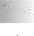
- the two-dimensional section shown in fig. 2 introduce a view of possible two-dimensional stator and rotor profiles thanks to which the blades offer favourable characteristics which are maintained in both operating modes:
- the first feature is particularly advantageous for 'slow' machines that operate with free inlet flow.
- the invention provides for the design of turbomachinery stage with:
- the invention achieves the scope with a method for the design of rotor and/or stator profiles of a bivalent axial turbomachinery stage comprising the steps of:
- a first embodiment there is the further step of selecting the half-thickness with derivative greater than or equal to zero up to the point of maximum half-thickness and less than or equal to zero after the point of maximum half-thickness.
- the parameters of the method are selected in such a way that the profile resulting from the application of said method has a symmetrical conformation with respect to the middle of the chord, a configuration that brings advantages in terms of lift and high efficiency over a wide operating range (otherwise a wide range of the inlet flow angle) both in turbine and operating machine operation.
- the symmetry with respect to the axis passing through the mid-chord point is obtained by setting the point of maximum deflection and the point of maximum thickness on said symmetry axis, or by setting the point of maximum deflection and maximum thickness at the 50% of the abscissa of the chord segment.
- the construction of the two-dimensional aerodynamic profile is achieved by defining its median segment and the corresponding thickness distribution by points.
- the points of the extrados (convex side) and of the intrados (concave side) corresponding to each point of the median segment are obtained respectively by adding and subtracting the half thickness, along the normal to the median segment.
- the airfoils are characterized by a leading edge and a trailing edge (where the leading edge is the first to be encountered). from the fluid passing through the blades, in the machine object of the present invention, the leading edge in operating mode becomes the trailing edge in turbine mode and vice versa.
- the bidirectional profile with deflection as defined allows to obtain better efficiency over a wide range of flow rate/working pressure and further advantages are obtained by using profiles with symmetrical geometry with respect to the mid-chord point, that is symmetrical with respect to a normal axis to the chord and passing through the midpoint of said segment.
- the profile of figs. 14a and 14b has been defined.
- the median segment 142 is conceived defined as an equidistant segment between the back 143 also known as the convex or extrados side and the belly 144 also known as the concave or intrados side.
- chord 141 or chord segment is a straight segment that joins the ends of the median segment; in the profile of figures 14a and 14b it is also possible to identify the front and rear edges 145 and 146 which in the profiles of blades for single use (only operator or only tractor) alternatively take the name of leading edge or leading edge and outlet or trailing edge depending on the flow of fluid passing through the stage.
- FIG 14a a Cartesian reference system XY is introduced where the abscissa axis is superimposed on the chord segment 141 and the origin of the axes coincides with the front edge 145.
- the axis 147 of the chord segment is also identified which passes through the midpoint 148 of said segment and with respect to which the profile 140 is constructed in a symmetrical manner.
- the geometry of the rotor and stator is created by defining the number of blades, the minimum and maximum radii and the blade sections with the procedure described above (2D profiles wind up on cylindrical surfaces). For each blade section the following are assigned:
- a possible embodiment provides that in the realization of a turbomachinery stage in accordance with the method object of the invention the following specific parameters are used: - for the rotor: Radius Chord Keying [cm] [cm] [°] 20 12.6 73.3 30 10.1 49.0 40 8.4 37.0 - for the stator: Radius Chord Keying [cm] [cm] [°] 20 10.9 66.3 30 11.3 76.3 40 11.7 81.6
- the machine described can be installed in the duct of a plant, or in a 'free ambient, where the machine is crossed by an external flow (for example in the case of a wind turbine) or sucks in flow from the outside (for example in the case of a fan).
- an external flow for example in the case of a wind turbine
- sucks in flow from the outside for example in the case of a fan
- a converging-diverging profiled duct has been studied as shown in figure 3 which allows an adequate recovery of static pressure at the exhaust pipe, presenting a section 31 with a section that narrows as it approaches the rotor, a section at constant section 32 containing the rotor and stator and a section 33 with a section which increases away from the stator.
- the conformation of these sections is an object of invention and will be described below.
- the fluid considered in all the work is air under standard conditions although it is expected that the turbomachinery can also operate with incompressible fluids such as water.
- the same fluid speed has been set at the respective inlets, while the rotation speeds used are 1500 rpm for the operating machine and 800 rpm for the turbine.
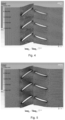
- Figures 4 and 5 show the fields of motion and static pressure for the 2 modes, highlighting how the flow at the outlet is almost axial (with no tangential component) for both.
- the operation of the 3D rotor-stator was initially simulated in a 'ducted' configuration, that is by inserting the stage in a duct and assigning the boundary conditions in the inlet and outlet sections of the duct.
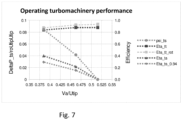
- the graph of Fig.7 shows the dimensionless global performance of interest:
- the total-to-total efficiency ( ⁇ tt) of the rotor alone and of the entire machine have maximum values close to or greater than 90% over a reasonably wide operating range.
- the total-to-static efficiency ( ⁇ ts) of the machine serves to highlight the efficiency of the machine operate with free discharge (condition in which the kinetic energy at the discharge is lost).
- FIG. 8 shows the field of motion that passes through the same machine in operation as driving machine (turbine) and the corresponding static pressure field on the blades.
- the reduced tangential component of the speed is highlighted at the exit which indicates the high capacity of extraction of work from the incoming flow. Also for this aspect is confirmed the good behaviour seen in the preliminary 2D simulation.
- the total-to-total efficiency ( ⁇ tt) of the rotor alone has a maximum value of just under 90%.
- the machine was housed inside a duct obtained by revolving an aerodynamic profile which characteristics, in an embodiment of the present invention, have been defined as a function of the sesigned Oulet Area /minimum area _ratio and in such a way to reduce the possibility of flow separation (limiting the curvature of the profile).
- the duct consists of:
- the surface that delimits the duct from the part of the root of the blades, in section 1), is a spherical cap with a radius equal to the minimum radius of the rotor blades (that is the radius of the rotating part of the hub or the root of the blades).
- the surface that delimits the duct from the part of the root of the blades, in section 3), is a spherical cap with a radius equal to the minimum radius of the stator blades (that is the radius of the fixed part of the hub or the root of the blades).
- the surface that delimits the duct from the part of the apex of the blades (rotor and stator), in sections 1), 2) and 3), is obtained by revolution of a two-dimensional shape or profile around the rotation axis of the machine.
- the two-dimensional shape consists of two portions of aerodynamic profile, used to define the sections 1) and 3), the ends of which are joined by straight sections.
- the portions of the aerodynamic profile are characterized similarly to what is done for the sections of the rotor and stator blades, that is by means of average line and thickness distribution.
- the two-dimensional profiles are defined by assigning the median segment and thickness distribution.
- a further detailed embodiment also not limiting, provides that the two-dimensional profile used for the section on the side of the rotor has:
- the ratio between the maximum and minimum passage areas of the duct section 3) is 2.1 (general maximum value 2.5).
- the two-dimensional profile used for the section on the stator side has:
- the specific geometry of the duct of the virtual prototype is an example of the general characteristics of the machine and does not limit the scope that can include other embodiments, even freely combines -able to each other.
- the simulation of the operating machine was carried out by inserting it between two separate ambients (typical reference configuration of test benches for fans according to the reference standards).
- the simulation of the driving machine was done by placing the machine in a single external ambient.
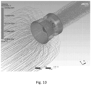
- Fig. 10 shows current lines that cross the machine in operating mode.
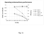
- the graph of Fig. 11 shows the dimensionless global performances which confirm the good behaviour seen for the fully ducted configuration.
- Fig. 12 shows the current lines that cross the same machine in operation as a turbine (entrance section from the left).
- the machine is in fact a wind turbine in an innovative configuration.
- the control system is therefore able to read the operating parameters of the machine combined with one or more preferably electric motors and, in an automatic or manual manner, activate suitable switching devices which vary the mode of the machine. which can be operated by said motor which absorbs energy from a source or can operate the commutated motor to generate electrical energy to be stored in suitable storage systems.
- suitable switching devices which vary the mode of the machine. which can be operated by said motor which absorbs energy from a source or can operate the commutated motor to generate electrical energy to be stored in suitable storage systems.
Landscapes
- Engineering & Computer Science (AREA)
- Mechanical Engineering (AREA)
- General Engineering & Computer Science (AREA)
- Combustion & Propulsion (AREA)
- Chemical & Material Sciences (AREA)
- Life Sciences & Earth Sciences (AREA)
- Sustainable Development (AREA)
- Sustainable Energy (AREA)
- Physics & Mathematics (AREA)
- Geometry (AREA)
- Fluid Mechanics (AREA)
- Power Engineering (AREA)
- Structures Of Non-Positive Displacement Pumps (AREA)
- Separation By Low-Temperature Treatments (AREA)
Claims (16)
- Verfahren zum Entwerfen von Rotor- und/oder Statorprofilen einer bivalenten Axialturbomaschine (1), die wahlweise im Antriebsmodus oder im Arbeitsmodus betrieben werden kann, wobei die Turbomaschine mindestens einen Stator (11) und einen Rotor (12) umfasst, die um eine Drehachse drehbar sind, wobei der Rotor und/oder der Stator eine Nabe (16, 15), einen Spinner und eine Vielzahl von im Wesentlichen die gleiche Form aufweisenden Schaufeln (14, 13, 155) umfasst, wobei jede der Schaufeln einen minimalen Radius (152), einen maximalen Radius (153) und ein dreidimensionales Schaufelprofil mit einem oder mehreren Schaufelabschnitten (1551, 1552, 1553) aufweist,wobei die Schaufelabschnitte (1551, 1552, 1553) die Form von zweidimensionalen aerodynamischen Profilen haben, die jeweils umfassen:- eine konkave Seite oder Unterseite (144);- eine konvexe Seite oder Oberseite (143);- ein Mittelsegment (142) als eine Gruppe von Punkten, die den Mittelpunkten aller in das zweidimensionale aerodynamische Profil eingeschriebenen Kreise entsprechen und tangential zu den Unterseiten- und Oberseitenlinien verlaufen;- eine Vorderkante (145) und eine Hinterkante (146) als Ort geometrischer Punkte, die jeweils den vorderen und hinteren Enden des Mittelsegments entsprechen;- eine Halbdicke als der Abstand zwischen dem Mittelsegment (142) und der Unterseite (144) oder der Oberseite (143), bewertet entlang der Normalen zum Mittelsegment (142) für jeden Punkt des Mittelsegments;- eine Sehne oder ein Sehnensegment (141) als das Segment, das die Enden des Mittelsegments (142) verbindet;- eine Krümmung oder Wölbung, die eine Funktion ist, die den Abstand darstellt, der sich zwischen der besagten Sehne und dem besagten Mittelsegment ergibt, wenn sie an den Punkten außerhalb der jeweiligen Enden nicht zusammenfallen; wobei das zweidimensionale aerodynamische Profil in einer kartesischen Bezugsebene (X, Y) durch Punkte beschrieben wird, die das Mittelsegment (142) zwischen der konkaven Seite oder Unterseite (144) und der konvexen Seite oder Oberseite (143) des Profils (140) darstellen, wobei die Sehne des Profils über die Abszisse (X) in der kartesischen Bezugsebene gelegt ist und der Ursprung der Achsen (0) der kartesischen Bezugsebene mit dem der Vorderkante benachbarten Ende der Sehne zusammenfällt,wobei das Verfahren umfasst- Auswählen des maximalen positiven Wertes der Wölbung;- Anordnen des maximalen Wölbungspunktes zwischen 40 % und 60 % der Abszisse der Sehne;- Auswählen der Ordinate des Mittelsegments mit einer Ableitung größer oder gleich Null bis zum Punkt der maximalen Wölbung und kleiner oder gleich Null nach dem Punkt der maximalen Wölbung;- Anordnen des Punktes der maximalen Halbdicke zwischen 40% und 60% der Abszisse der Sehne;- Auswählen des Radius der Vorderkante (145) und der Hinterkante (146) mit Werten, die größer oder gleich 3 % der Länge des Sehnensegments sind.
- Verfahren nach Anspruch 1, umfassend den weiteren Schritt des Auswählens der Halbdicke mit einer Ableitung größer oder gleich Null für Abszissenwerte (X) vom Ursprung der Achsen (0) bis zum Punkt der maximalen Halbdicke und kleiner oder gleich Null für nachfolgende Werte der Abszisse (X) nach dem Punkt der maximalen Halb dicke.
- Verfahren nach Anspruch 1 oder 2, wobei- der Punkt der maximalen Wölbung liegt bei 50 % der Abszisse des Sehnensegments.- der Punkt der maximalen Halbdicke liegt bei 50 % der Abszisse des Sehnensegments.- der Wert des Radius der Anströmkante (145) mit dem Wert des Radius der Hinterkante (146) übereinstimmt; dadurch wird eine in Bezug auf die Achse symmetrische Formgebung eingeführt und die zweidimensionalen aerodynamischen Profile haben eine geometrisch symmetrische Formgebung in Bezug auf die Achse (147), die orthogonal zum Sehnensegment (141) ist und durch den Mittelpunkt (148) des Sehnensegments verläuft.
- Verfahren nach einem oder mehreren der vorhergehenden Ansprüche, das ferner folgende Schritte umfasst:- Definieren der Anzahl der Schaufeln, die den Rotor oder Stator bilden und entlang eines konzentrischen Umfangs zur Drehachse (151) des Rotors oder Stators verteilt sind;- Definieren des Wertes des maximalen Radius des Rotors oder Stators und des Wertes der minimalen (152) und maximalen (153) Schaufelradien für den Rotor oder Stator;- Identifizieren eines Schaufelabschnitts (1551, 1552, 1553), der durch da Schneiden der Schaufel (155) mit einer insbesondere zylindrischen Rotationsfläche (1541, 1542, 1543) eines koaxial zur Drehachse (151) des Rotors und/oder Stators angeordneten Rotationskörpers erhalten wird, wobei die Fläche durch einen bestimmten Radiuswert (r1541, r1542, r1543) für jeden Punkt der Achse der Rotationsfläche definiert ist und daher der Schaufelabschnitt (1551, 1552, 1553) ist, der durch das Schneiden der Schaufel (155) mit der Rotationsfläche in einem mit dem Radius der Rotationsfläche zusammenfallenden radialen Abstand erhalten wird.- Definieren einer diskreten Anzahl der Schaufelabschnitte (1551, 1552, 1553), wobei eine entsprechende diskrete Anzahl der Radiuswerte der Rotationsfläche (r1541, r1542, r1543) definiert wurde, wobei die Radiuswerte zwischen dem minimalen (152) und maximalen Schaufelradius (153) des Rotors oder Stators für jeden Punkt der Drehachse liegen;- Erstellen eines zweidimensionalen aerodynamischen Profils (140) für jeden der genannten Abschnitte und für jede Schaufel, dessen Verkeilung oder Winkelausrichtung in Bezug auf die Radialachse der besagten Rotationsfläche und dessen Abmessungen bei gleichbleibender Form vorbestimmte und variierende Werte in Abhängigkeit von dem Referenzabschnitt annehmen;- Interpolieren zwischen den Formen der verschiedenen Abschnitte der zweidimensionalen aerodynamischen Profile jeder Schaufel mittels computergestützter Verarbeitung, um die dreidimensionale Oberfläche zu definieren, die für die Schaufel selbst repräsentativ ist, wobei die zweidimensionalen aerodynamischen Profile die Abschnitte jeder Schaufel darstellen; wobei das zweidimensionale aerodynamische Profil eine geometrisch symmetrische Formgebung in Bezug auf die Achse (147) hat, die orthogonal zu dem Sehnensegment (141) ist und durch den Mittelpunkt (148) des Sehnensegments verläuft.
- Verfahren nach einem oder mehreren der vorhergehenden Ansprüche, ferner gekennzeichnet durch die folgenden Parameter:- Verhältnis zwischen der maximalen Dicke des Profils und der Länge der Sehne gleich 0,1;- Abstand zwischen dem Mittelsegment (142) und dem Sehnensegment nicht größer als 4 % der Sehnenlänge für jeden Punkt des besagten Sehnensegments;- Winkel zwischen dem Mittelsegment (142) und der Vorderkante (145) gleich 9 Sexagesimalgrad;- Winkel zwischen dem Mittelsegment (142) und der Hinterkante (146) gleich -9 Sexagesimalgrad;- Radius der beiden Kanten gleich 4,5 % der Sehne.
- Verfahren zum Entwerfen von Gehäuseleitungen für die bivalente axiale Turbomaschinenstufe (1), die nach dem in einem oder mehreren der Ansprüche 1 bis 5 beschriebenen Verfahren entworfen ist, umfassend einen Stator (11) und einen Rotor (12), die jeweils eine Nabe (16, 15), einen Spinner und eine Mehrzahl von Schaufeln (14, 13) umfassen, wobei jede Schaufel einen jeweiligen minimalen und maximalen Schaufelradius aufweist, wobei die Schaufeln nach dem Verfahren eines oder mehrerer der vorhergehenden Ansprüche entworfen sind, umfassend die Schritte:- Definieren des Profils der Spinner des Rotors und des Stators;- Definieren der Gehäuseleitung als eine Anordnung aus:- einem Teil mit konstantem Querschnitt (31), der den Rotor und den Stator enthält;- Einlassabschnitt (32) zum Rotor;- Einlassabschnitt (33) zum Stator;- Definieren der Oberfläche der Eingangsabschnitte des Rotors und des Stators als eine Rotation eines zweidimensionalen Profils um die Drehachse des Rotors; wobei das Verfahren gekennzeichnet ist durch:- Definieren des Profils des Rotor-Spinners (12) als Halbkugel mit einem Radius, der im Wesentlichen gleich dem minimalen Radius der Rotorblätter oder dem Radius der Nabe (16) des Rotors ist;- Definieren des Profils des Stator-Spinners (11) als Halbkugel mit einem Radius, der im Wesentlichen gleich dem minimalen Radius der Statorschaufeln oder dem Radius der Nabe (15) des Stators ist;- Definieren des zweidimensionalen Profils für den Rotorabschnitt als Teil eines in Bezug auf die Mittelsehne symmetrischen zweidimensionalen Tragflächenprofils;- Definieren des zweidimensionalen Profils für den Statorabschnitt als Teil eines in Bezug auf die Mittelsehne symmetrischen zweidimensionalen Tragflächenprofils.
- Verfahren nach Anspruch 6, wobei das zweidimensionale Tragflächenprofil umfasst:- eine konkave Seite oder Unterseite (144);- eine konvexe Seite oder Oberseite (143);- ein Mittelsegment (142) als eine Gruppe von Punkten, die dem Mittelpunkt aller in das zweidimensionale aerodynamische Profil eingeschriebenen Kreise entsprechen und tangential zu den Unterseiten- und Oberseitenlinien verlaufen;- eine Vorderkante (145) und eine Hinterkante (146) als geometrische Punkte, die jeweils mit den vorderen und hinteren Ende des Mittelsegments übereinstimmen;- eine Halbdicke als der Abstand zwischen dem Mittelsegment (142) und der Unterseite (144) oder der Oberseite (143), bewertet entlang der Normalen zum Mittelsegment (142) für jeden Punkt des Mittelsegments;- eine Sehne oder ein Sehnensegment (141) als das Segment, das die Enden des Mittelsegments (142) verbindet;eine Wölbung oder eine Funktion, die den Abstand darstellt, der sich zwischen der besagten Sehne und dem besagten Mittelsegment ergibt, wenn sie in den Punkten außerhalb der jeweiligen Enden nicht zusammenfallen; wobei das zweidimensionale aerodynamische Profil für Rotorleitung ist durch die folgenden Parameter weiter definiert:- Länge des Halbsehnensegments mit einem Wert, der das 1,5-fache des maximalen Schaufelradius nicht überschreitet, und vorzugsweise einen Wert von 1,25 hat;- Wölbungswert kleiner als 25 % der Länge des Halbsehnensegments und vorzugsweise gleich 24 %;- Maximale Dicke gleich 30 % der Länge des Halbsehnensegments;und bei dem die Statorleitung durch folgende Parameter weiter definiert ist:- Länge des Halbsehnensegments mit einem Wert, der das 1,25-fache des maximalen Schaufelradius nicht überschreitet, und vorzugsweise einen Wert von 0,75 hat;- Wölbungswert kleiner als 20% der Länge des Halbsehnensegments und vorzugsweise gleich 18%;- Maximale Dicke gleich 50% der Länge des Halbsehnensegments.
- Verfahren zur Verwendung einer Turbomaschinenstufe, die nach dem in einem oder mehreren der Ansprüche 1 bis 5 beschriebenen Verfahren hergestellt wurde, wobei der Rotor durch die kinetische Energie einer durch ihn strömenden Flüssigkeit angetrieben wird.
- Verfahren zur Verwendung einer Turbomaschinenstufe, die nach dem in einem oder mehreren der Ansprüche 1 bis 5 beschriebenen Verfahren hergestellt wurde, bei dem der Rotor kinetische Energie an eine ihn durchströmende Fluidströmung überträgt.
- Bivalente axiale Turbomaschinenstufe (1), die wahlweise im Antriebs- oder Arbeitsmodus arbeiten kann, umfassend:- einen Rotor (12), der seinerseits eine Rotornabe (16) und eine vorbestimmte Anzahl von Rotorschaufeln (14) umfasst;- einen Stator (11), der seinerseits eine Statornabe (15) und eine vorbestimmte Anzahl von Statorschaufeln (13) umfasst;wobei die Schaufeln durch zweidimensionale aerodynamische Profile beschrieben werden, wobei die Turbomaschinenstufe dadurch gekennzeichnet ist, dass sie ein Rotor- und Statorprofil aufweist, das nach dem Verfahren der Ansprüche 1 bis 5 hergestellt wird.
- Turbomaschinenstufe nach Anspruch 10, umfassend eine Leitung zur Aufnahme der Rotor- und Statorelemente, die nach dem Verfahren der Ansprüche 6 bis 7 hergestellt wurde.
- Turbomaschinenstufe nach Anspruch 10 oder 11, die in einem kompressiblen oder inkompressiblen Fluid, vorzugsweise in Luft oder Wasser, arbeitet.
- Turbomaschinenstufe nach einem oder mehreren der vorhergehenden Ansprüche 10 bis 12, bei der die Drehzahl des Rotors im Antriebsmodus von der Rotordrehzahl des Rotors im Arbeitsmodus verschieden ist.
- Turbomaschinenstufe nach einem oder mehreren der vorhergehenden Ansprüche 10 bis 13, bei der die folgenden Parameter des Entwurfsverfahrens vorgegeben sind:- Anzahl der Rotorblätter: 15- Anzahl der Statorschaufeln: 15- Anzahl der Rotorschaufelabschnitte: 3- Minimaler Radius des Rotorblatts: 20 cm- Maximaler Radius des Rotorblattes: 40 cm- Sehnengröße und Anstellwinkel gemäß der folgenden Tabelle:
Radius Sehne Keilung [cm] [cm] [°] 20 12.6 73.3 30 10.1 49.0 40 8.4 37.0 - Anzahl der Statorschaufelabschnitte: 3- Minimaler Radius des Statorblatts: 20 cm- Maximaler Radius des Statorblattes: 40 cm- Sehnengröße und Anstellwinkel gemäß der folgenden Tabelle:Radius Sehne Keilung [cm] [cm] [°] 20 10.9 66.3 30 11.3 76.3 40 11.7 81.6 - Turbomaschinenstufe nach einem oder mehreren der vorhergehenden Ansprüche 10 bis 14, bei der die Nenndrehzahl des Rotors zwischen 10 und 5000 Umdrehungen pro Minute und vorzugsweise zwischen 500 und 2000 Umdrehungen pro Minute und noch bevorzugter von 1500 +/- 10% Umdrehungen pro Minute für den Arbeitsmodus und 800 +/- 10% Umdrehungen pro Minute für den Antriebsmodus umfasst ist.
- Turbomaschinenstufe nach einem oder mehreren der vorhergehenden Ansprüche 10 bis 15 in Kombination mit einem Steuersystem, mindestens einer Energiequelle und mindestens einem Energiespeicherelement, mindestens einem mit dem Rotor kombinierten Motor, einem oder mehreren Sensoren, einem oder mehreren Steuerorganen für ein oder mehrere Schaltorgane des Arbeitsmodus der Stufe, wobei das Steuersystem an der Umschaltung der Turbomaschine vom Antriebsmodus in den Arbeitsmodus und umgekehrt beteiligt ist.
Applications Claiming Priority (2)
| Application Number | Priority Date | Filing Date | Title |
|---|---|---|---|
| IT102020000012712A IT202000012712A1 (it) | 2020-05-28 | 2020-05-28 | Turbomacchina assiale reversibile |
| PCT/IB2021/054535 WO2021240366A1 (en) | 2020-05-28 | 2021-05-25 | Bivalent axial turbomachinery |
Publications (3)
| Publication Number | Publication Date |
|---|---|
| EP4158182A1 EP4158182A1 (de) | 2023-04-05 |
| EP4158182C0 EP4158182C0 (de) | 2024-07-17 |
| EP4158182B1 true EP4158182B1 (de) | 2024-07-17 |
Family
ID=72178980
Family Applications (1)
| Application Number | Title | Priority Date | Filing Date |
|---|---|---|---|
| EP21736363.9A Active EP4158182B1 (de) | 2020-05-28 | 2021-05-25 | Bivalente axialturbomaschine |
Country Status (3)
| Country | Link |
|---|---|
| EP (1) | EP4158182B1 (de) |
| IT (1) | IT202000012712A1 (de) |
| WO (1) | WO2021240366A1 (de) |
Families Citing this family (2)
| Publication number | Priority date | Publication date | Assignee | Title |
|---|---|---|---|---|
| CN115730532B (zh) * | 2022-11-17 | 2025-07-01 | 山东大学 | 一种径流式透平批量一维设计及设计空间可视化的方法 |
| CN116066178B (zh) * | 2023-01-18 | 2026-02-27 | 西北工业大学 | 耦合非轴对称端壁结构的变几何涡轮导叶组件及造型方法 |
Family Cites Families (5)
| Publication number | Priority date | Publication date | Assignee | Title |
|---|---|---|---|---|
| US3343512A (en) * | 1966-05-20 | 1967-09-26 | Francis R Rasmussen | Hydrofoil with unsymmetrical nose profile |
| GB1383070A (en) * | 1971-12-13 | 1975-02-05 | Boeing Co | Hydrodynamic sections |
| NL9400050A (nl) * | 1994-01-12 | 1995-08-01 | Tocardo B V | Inrichting voor het opwekken van energie uit de stromende beweging van een fluidum. |
| CA2481820C (en) * | 2004-09-17 | 2009-09-01 | Clean Current Power Systems Incorporated | Flow enhancement for underwater turbine generator |
| JP2015031238A (ja) * | 2013-08-06 | 2015-02-16 | 株式会社デンソー | プロペラファン式送風機/発電機 |
-
2020
- 2020-05-28 IT IT102020000012712A patent/IT202000012712A1/it unknown
-
2021
- 2021-05-25 WO PCT/IB2021/054535 patent/WO2021240366A1/en not_active Ceased
- 2021-05-25 EP EP21736363.9A patent/EP4158182B1/de active Active
Also Published As
| Publication number | Publication date |
|---|---|
| IT202000012712A1 (it) | 2021-11-28 |
| WO2021240366A1 (en) | 2021-12-02 |
| EP4158182A1 (de) | 2023-04-05 |
| EP4158182C0 (de) | 2024-07-17 |
Similar Documents
| Publication | Publication Date | Title |
|---|---|---|
| US20110194938A1 (en) | Segmented wind turbine airfoil/blade | |
| EP4158182B1 (de) | Bivalente axialturbomaschine | |
| WO2009103528A2 (en) | Parametric blades with either sinusoidal lean or airfoils with arcs of ellipses | |
| CN113742861B (zh) | 一种适用于风力发电机风洞试验的叶片模型优化设计方法 | |
| Denantes et al. | Counter-rotating turbines for solar chimney power plants | |
| US10914315B2 (en) | Gas turbine engine airfoil | |
| CN108678960B (zh) | 一种高效对旋轴流泵 | |
| CN109312757A (zh) | 低噪音高效率离心式鼓风机 | |
| WO2018111665A1 (en) | A power generation system and method for operating same | |
| WO2012166625A1 (en) | Turbine with unevenly loaded rotor blades | |
| CN205858418U (zh) | 一种倾斜轴式变几何动力涡轮导叶 | |
| CN109505788B (zh) | 可逆轴流风机 | |
| CN216618004U (zh) | 涡轮转子、膨胀机和空气循环机 | |
| JP2007517155A (ja) | 風力タービンエンジン | |
| US4120609A (en) | Sheet metal fan | |
| CN115978006A (zh) | 具有静叶结构的风扇装置 | |
| CN112483436B (zh) | 一种压缩膨胀一体化涡轮机组 | |
| CN109798258B (zh) | 一种风机气动结构 | |
| Satwika et al. | Investigation flow on horizontal axis wind turbine with Betz chord distribution, twist, and winglet | |
| CN113898607A (zh) | 叶轮机械的叶片相贯线、叶片的设计方法及叶轮机械的叶片 | |
| JP7080470B2 (ja) | 二重反転式羽根車及び流体機械 | |
| CN113931847A (zh) | 一种可逆式对旋轴流泵 | |
| CN206352585U (zh) | 一种高效大前掠型斜流风机 | |
| JP6709741B2 (ja) | ロータ | |
| CN115370610B (zh) | 中比转速高效鼓风机三元流曲面离心叶轮系列 |
Legal Events
| Date | Code | Title | Description |
|---|---|---|---|
| STAA | Information on the status of an ep patent application or granted ep patent |
Free format text: STATUS: UNKNOWN |
|
| STAA | Information on the status of an ep patent application or granted ep patent |
Free format text: STATUS: THE INTERNATIONAL PUBLICATION HAS BEEN MADE |
|
| PUAI | Public reference made under article 153(3) epc to a published international application that has entered the european phase |
Free format text: ORIGINAL CODE: 0009012 |
|
| STAA | Information on the status of an ep patent application or granted ep patent |
Free format text: STATUS: REQUEST FOR EXAMINATION WAS MADE |
|
| 17P | Request for examination filed |
Effective date: 20221020 |
|
| AK | Designated contracting states |
Kind code of ref document: A1 Designated state(s): AL AT BE BG CH CY CZ DE DK EE ES FI FR GB GR HR HU IE IS IT LI LT LU LV MC MK MT NL NO PL PT RO RS SE SI SK SM TR |
|
| DAV | Request for validation of the european patent (deleted) | ||
| DAX | Request for extension of the european patent (deleted) | ||
| RIC1 | Information provided on ipc code assigned before grant |
Ipc: F04D 29/54 20060101ALI20240115BHEP Ipc: F03B 17/06 20060101ALI20240115BHEP Ipc: F04D 29/18 20060101ALI20240115BHEP Ipc: F04D 29/32 20060101ALI20240115BHEP Ipc: F03D 1/06 20060101ALI20240115BHEP Ipc: F03D 1/04 20060101ALI20240115BHEP Ipc: F03B 3/04 20060101AFI20240115BHEP |
|
| GRAP | Despatch of communication of intention to grant a patent |
Free format text: ORIGINAL CODE: EPIDOSNIGR1 |
|
| STAA | Information on the status of an ep patent application or granted ep patent |
Free format text: STATUS: GRANT OF PATENT IS INTENDED |
|
| INTG | Intention to grant announced |
Effective date: 20240305 |
|
| GRAS | Grant fee paid |
Free format text: ORIGINAL CODE: EPIDOSNIGR3 |
|
| GRAA | (expected) grant |
Free format text: ORIGINAL CODE: 0009210 |
|
| STAA | Information on the status of an ep patent application or granted ep patent |
Free format text: STATUS: THE PATENT HAS BEEN GRANTED |
|
| AK | Designated contracting states |
Kind code of ref document: B1 Designated state(s): AL AT BE BG CH CY CZ DE DK EE ES FI FR GB GR HR HU IE IS IT LI LT LU LV MC MK MT NL NO PL PT RO RS SE SI SK SM TR |
|
| REG | Reference to a national code |
Ref country code: CH Ref legal event code: EP |
|
| REG | Reference to a national code |
Ref country code: DE Ref legal event code: R096 Ref document number: 602021015869 Country of ref document: DE |
|
| REG | Reference to a national code |
Ref country code: IE Ref legal event code: FG4D |
|
| U01 | Request for unitary effect filed |
Effective date: 20240723 |
|
| U07 | Unitary effect registered |
Designated state(s): AT BE BG DE DK EE FI FR IT LT LU LV MT NL PT SE SI Effective date: 20240802 |
|
| PG25 | Lapsed in a contracting state [announced via postgrant information from national office to epo] |
Ref country code: NO Free format text: LAPSE BECAUSE OF FAILURE TO SUBMIT A TRANSLATION OF THE DESCRIPTION OR TO PAY THE FEE WITHIN THE PRESCRIBED TIME-LIMIT Effective date: 20241017 |
|
| PG25 | Lapsed in a contracting state [announced via postgrant information from national office to epo] |
Ref country code: GR Free format text: LAPSE BECAUSE OF FAILURE TO SUBMIT A TRANSLATION OF THE DESCRIPTION OR TO PAY THE FEE WITHIN THE PRESCRIBED TIME-LIMIT Effective date: 20241018 Ref country code: PL Free format text: LAPSE BECAUSE OF FAILURE TO SUBMIT A TRANSLATION OF THE DESCRIPTION OR TO PAY THE FEE WITHIN THE PRESCRIBED TIME-LIMIT Effective date: 20240717 |
|
| PG25 | Lapsed in a contracting state [announced via postgrant information from national office to epo] |
Ref country code: IS Free format text: LAPSE BECAUSE OF FAILURE TO SUBMIT A TRANSLATION OF THE DESCRIPTION OR TO PAY THE FEE WITHIN THE PRESCRIBED TIME-LIMIT Effective date: 20241117 |
|
| PG25 | Lapsed in a contracting state [announced via postgrant information from national office to epo] |
Ref country code: HR Free format text: LAPSE BECAUSE OF FAILURE TO SUBMIT A TRANSLATION OF THE DESCRIPTION OR TO PAY THE FEE WITHIN THE PRESCRIBED TIME-LIMIT Effective date: 20240717 |
|
| PG25 | Lapsed in a contracting state [announced via postgrant information from national office to epo] |
Ref country code: ES Free format text: LAPSE BECAUSE OF FAILURE TO SUBMIT A TRANSLATION OF THE DESCRIPTION OR TO PAY THE FEE WITHIN THE PRESCRIBED TIME-LIMIT Effective date: 20240717 Ref country code: RS Free format text: LAPSE BECAUSE OF FAILURE TO SUBMIT A TRANSLATION OF THE DESCRIPTION OR TO PAY THE FEE WITHIN THE PRESCRIBED TIME-LIMIT Effective date: 20241017 |
|
| PG25 | Lapsed in a contracting state [announced via postgrant information from national office to epo] |
Ref country code: RS Free format text: LAPSE BECAUSE OF FAILURE TO SUBMIT A TRANSLATION OF THE DESCRIPTION OR TO PAY THE FEE WITHIN THE PRESCRIBED TIME-LIMIT Effective date: 20241017 Ref country code: PL Free format text: LAPSE BECAUSE OF FAILURE TO SUBMIT A TRANSLATION OF THE DESCRIPTION OR TO PAY THE FEE WITHIN THE PRESCRIBED TIME-LIMIT Effective date: 20240717 Ref country code: NO Free format text: LAPSE BECAUSE OF FAILURE TO SUBMIT A TRANSLATION OF THE DESCRIPTION OR TO PAY THE FEE WITHIN THE PRESCRIBED TIME-LIMIT Effective date: 20241017 Ref country code: IS Free format text: LAPSE BECAUSE OF FAILURE TO SUBMIT A TRANSLATION OF THE DESCRIPTION OR TO PAY THE FEE WITHIN THE PRESCRIBED TIME-LIMIT Effective date: 20241117 Ref country code: HR Free format text: LAPSE BECAUSE OF FAILURE TO SUBMIT A TRANSLATION OF THE DESCRIPTION OR TO PAY THE FEE WITHIN THE PRESCRIBED TIME-LIMIT Effective date: 20240717 Ref country code: GR Free format text: LAPSE BECAUSE OF FAILURE TO SUBMIT A TRANSLATION OF THE DESCRIPTION OR TO PAY THE FEE WITHIN THE PRESCRIBED TIME-LIMIT Effective date: 20241018 Ref country code: ES Free format text: LAPSE BECAUSE OF FAILURE TO SUBMIT A TRANSLATION OF THE DESCRIPTION OR TO PAY THE FEE WITHIN THE PRESCRIBED TIME-LIMIT Effective date: 20240717 |
|
| PG25 | Lapsed in a contracting state [announced via postgrant information from national office to epo] |
Ref country code: SM Free format text: LAPSE BECAUSE OF FAILURE TO SUBMIT A TRANSLATION OF THE DESCRIPTION OR TO PAY THE FEE WITHIN THE PRESCRIBED TIME-LIMIT Effective date: 20240717 |
|
| PG25 | Lapsed in a contracting state [announced via postgrant information from national office to epo] |
Ref country code: CZ Free format text: LAPSE BECAUSE OF FAILURE TO SUBMIT A TRANSLATION OF THE DESCRIPTION OR TO PAY THE FEE WITHIN THE PRESCRIBED TIME-LIMIT Effective date: 20240717 |
|
| PG25 | Lapsed in a contracting state [announced via postgrant information from national office to epo] |
Ref country code: SK Free format text: LAPSE BECAUSE OF FAILURE TO SUBMIT A TRANSLATION OF THE DESCRIPTION OR TO PAY THE FEE WITHIN THE PRESCRIBED TIME-LIMIT Effective date: 20240717 |
|
| PLBE | No opposition filed within time limit |
Free format text: ORIGINAL CODE: 0009261 |
|
| STAA | Information on the status of an ep patent application or granted ep patent |
Free format text: STATUS: NO OPPOSITION FILED WITHIN TIME LIMIT |
|
| U20 | Renewal fee for the european patent with unitary effect paid |
Year of fee payment: 5 Effective date: 20250428 |
|
| 26N | No opposition filed |
Effective date: 20250422 |
|
| REG | Reference to a national code |
Ref country code: CH Ref legal event code: H13 Free format text: ST27 STATUS EVENT CODE: U-0-0-H10-H13 (AS PROVIDED BY THE NATIONAL OFFICE) Effective date: 20251223 |
|
| PG25 | Lapsed in a contracting state [announced via postgrant information from national office to epo] |
Ref country code: CH Free format text: LAPSE BECAUSE OF NON-PAYMENT OF DUE FEES Effective date: 20250531 |
|
| GBPC | Gb: european patent ceased through non-payment of renewal fee |
Effective date: 20250525 |
|
| PG25 | Lapsed in a contracting state [announced via postgrant information from national office to epo] |
Ref country code: MC Free format text: LAPSE BECAUSE OF FAILURE TO SUBMIT A TRANSLATION OF THE DESCRIPTION OR TO PAY THE FEE WITHIN THE PRESCRIBED TIME-LIMIT Effective date: 20240717 |
|
| PG25 | Lapsed in a contracting state [announced via postgrant information from national office to epo] |
Ref country code: GB Free format text: LAPSE BECAUSE OF NON-PAYMENT OF DUE FEES Effective date: 20250525 |
|
| PG25 | Lapsed in a contracting state [announced via postgrant information from national office to epo] |
Ref country code: IE Free format text: LAPSE BECAUSE OF NON-PAYMENT OF DUE FEES Effective date: 20250525 |
|
| PG25 | Lapsed in a contracting state [announced via postgrant information from national office to epo] |
Ref country code: RO Free format text: LAPSE BECAUSE OF FAILURE TO SUBMIT A TRANSLATION OF THE DESCRIPTION OR TO PAY THE FEE WITHIN THE PRESCRIBED TIME-LIMIT Effective date: 20240717 |