EP4158217B1 - Système de freinage de vehicule - Google Patents
Système de freinage de vehicule Download PDFInfo
- Publication number
- EP4158217B1 EP4158217B1 EP21722969.9A EP21722969A EP4158217B1 EP 4158217 B1 EP4158217 B1 EP 4158217B1 EP 21722969 A EP21722969 A EP 21722969A EP 4158217 B1 EP4158217 B1 EP 4158217B1
- Authority
- EP
- European Patent Office
- Prior art keywords
- magnet
- braking system
- orifice
- reservoir
- support plate
- Prior art date
- Legal status (The legal status is an assumption and is not a legal conclusion. Google has not performed a legal analysis and makes no representation as to the accuracy of the status listed.)
- Active
Links
Images


Classifications
-
- F—MECHANICAL ENGINEERING; LIGHTING; HEATING; WEAPONS; BLASTING
- F16—ENGINEERING ELEMENTS AND UNITS; GENERAL MEASURES FOR PRODUCING AND MAINTAINING EFFECTIVE FUNCTIONING OF MACHINES OR INSTALLATIONS; THERMAL INSULATION IN GENERAL
- F16D—COUPLINGS FOR TRANSMITTING ROTATION; CLUTCHES; BRAKES
- F16D65/00—Parts or details
- F16D65/0031—Devices for retaining friction material debris, e.g. dust collectors or filters
Definitions
- One aspect of the invention relates to a vehicle braking system constructed and arranged to collect particles emitted during braking.
- a vehicle in particular an automobile, comprising a vehicle braking system constructed and arranged to collect particles emitted during braking.
- Motor vehicles have braking systems comprising linings equipped with friction materials delivering pressure to discs or drums rotatably connected to the vehicle's wheels, in order to apply a braking torque to them.
- Vehicle braking causes abrasion wear of the friction materials, as well as reduced wear of the metal discs, which generate particles dispersed in the ambient air producing pollution of this air.
- Anti-pollution standards will impose in the future limitations on the emissions of polluting particles coming from braking.
- a known device for recovering particles emitted by disc brakes presented in particular by the document EP-A1-2309146 uses holes made in the brake linings. These holes pass through the linings to conduct particles emitted between the friction material and one face of the disc to a rear cavity containing a magnet.
- the particles of the friction materials containing metal elements, and the metal particles of the discs are attracted by the magnet arranged flat at the bottom of the cavity, parallel to the lining, in order to accumulate in this cavity forming a reservoir to prevent dispersion in the air.
- the reservoir is removed to empty the particles.
- the magnet which is placed flat at the bottom of the tank, gradually becomes covered with particles. As it is relatively far from the front face of the lining resting on the disc, its magnetic field near the abrasion zone is weak.
- FR 3 086 023 A1 further discloses a constructed vehicle braking system, comprising a first magnet, an external reservoir facing an orifice of a support plate of the external brake lining, said external reservoir opening onto said support plate and comprising a second magnet.
- the aim of the invention is to overcome the drawbacks of the prior art by proposing a vehicle braking system constructed and arranged to collect particles emitted during braking, the particle collection efficiency of which is high.
- the invention thus relates, in its broadest acceptance, to a vehicle braking system as defined in the attached independent claim 1, constructed and arranged to collect particles emitted during braking, the braking system comprising a caliper supporting an internal brake lining and an external brake lining each comprising a support plate and a friction layer.
- the raised faces of the first and second magnets allow the maximum collection of particles emitted during braking. Indeed, this relief allows the surface area of attraction and collection of particles to be maximized. This then results in a reduction, or even elimination, of the release of particles emitted during braking into the air.
- the vehicle braking system constructed and arranged to collect particles emitted during braking may have one or more additional characteristics among the following, considered individually or in all technically possible combinations.
- the internal reservoir is provided in a piston of the braking system.
- At least one peripheral storage area is provided between the internal surface of the internal or external reservoir and the external surface of the first magnet or second magnet.
- the first magnet and the second magnet have a different length.
- a groove is provided in at least one of the friction layers, the groove opening into the orifice.
- This orifice is that of the friction layer comprising said groove.
- At least one of the first or second magnets is neodymium-iron-boron.
- the invention relates to a vehicle comprising two braking systems constructed and arranged to collect particles emitted during braking according to any of the aforementioned aspects of the invention.
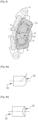
- FIG. 1 illustrates a vehicle braking system 1 according to one aspect of the invention.
- the braking system 1 is assembled on a brake disc 2.
- the braking system 1 comprises a caliper 3 supporting an internal brake lining and an external brake lining each comprising a support plate and a friction layer.
- FIG 2 is a sectional view of the braking system 1 shown in figure 1 .
- the braking system 1 comprises a caliper 3.
- This caliper 3 supports an internal braking lining 4 and an external braking lining 5 each comprising a support plate 4 1 , 5 1 and a friction layer 4 2 , 5 2 .
- the internal brake lining 4 has an orifice 6 passing through the thickness E of the internal lining 4 and the external brake lining 5 has an orifice 6 passing through the thickness E of the external lining 5.
- the braking system 1 further comprises an internal reservoir 7 facing the orifice 6 and opening onto the support plate 41 of the internal braking lining 4.
- the internal reservoir 7 is arranged in a piston of the braking system 1.
- a first magnet 8 is arranged in the internal reservoir 7.
- the braking system 1 also comprises an external reservoir 9 opposite the orifice 6 and opening onto the support plate 51 of the external braking lining 5.
- a second magnet 10 is arranged in the external reservoir 9.
- the face 11 of the first magnet 8 opposite the through hole 6 is in relief. More particularly, in this example the relief is formed by a curved surface.
- the face 12 of the second magnet 10 opposite the through hole 6 is in relief. More particularly, in this example the relief is formed by a curved surface.
- the second magnet 10 has a length L10 less than the length L8 of the first magnet 8.
- first magnet 8 and the second magnet 10 may have a similar length.
- a peripheral storage area Z8 is provided between the inner surface of the inner reservoir 7 and the outer surface of the first magnet 8.
- a spacer 13 is arranged between the inner surface of the inner reservoir 7 and the outer surface of the first magnet 8.
- a peripheral storage area Z10 is provided between the internal surface of the external reservoir 9 and the external surface of the second magnet 10.
- a shoulder is provided at the bottom of the external reservoir 9.
- the metallically charged particles P generated during braking are attracted by the surfaces 11 and 12 of the first magnet 8 and the second magnet 9 opposite the orifices 6.
- the particles P therefore pass through the orifices 6 to come to stick to the surfaces 11 and 12 of the first magnet 8 and the second magnet 10.
- the new particles come to push the particles previously deposited towards the bottom of the internal tank 7 or external tank 9.
- FIG. 3 illustrates an exemplary embodiment of a brake lining according to one aspect of the invention. More particularly, in this embodiment, a groove R is formed in the friction layer 5 2 of the external lining 5.
- the groove R follows the periphery of the friction layer 5 2 and also opens into the orifice 6 passing through the thickness of the external lining 5.
- some of the particles P generated during braking go directly towards the orifice 6 and then stick to the raised surface 12 of the magnet 10.
- Other particles are collected by the groove R.
- the particles collected by the groove R are then attracted by the magnet 10. They therefore move in the groove R and pass through the orifice 6 to stick to the raised surface 12 of the magnet 10. The particles thus collected can then be recovered during a maintenance phase of the vehicle.
- the raised surface 12 of the magnet 10 intended to be positioned opposite the orifice 6 of the external lining 5 is curved.
- FIG. 4a is a bottom view of a magnet 10 provided with such a domed surface 12 and the Figure 4b is a front view of this magnet 10.
- the radius of curvature r of this curved surface 12 can be of the order of 20 mm. It is understood that the raised surface 11 of the magnet 8 can also be curved.
- the raised surface 12 of the magnet 10 intended to be positioned opposite the orifice 6 of the external lining 5 is chamfered.
- FIG. 5a is a bottom view of a magnet 10 provided with such a chamfered surface comprising two chamfers and the Figure 5b is a front view of this magnet 10.
- the angle ⁇ between these two chamfers can be of the order of 120°. It is understood that the raised surface 11 of the magnet 8 can also be chamfered.
- the raised surface 12 of the magnet 10 intended to be positioned opposite the orifice 6 of the external brake lining 5 does not have two chamfers but four chamfers.
- figure 6 illustrates a top view of this magnet 10 whose raised surface 12 intended to be positioned opposite the orifice 6 comprises four chamfers. It is understood that the raised surface 11 of the magnet 8 can also comprise four chamfers.
- the surface 12 of the magnet 10 intended to be positioned opposite an orifice 6 is spherical.
- the raised surface 11 of the magnet 8 can be spherical.
Landscapes
- Engineering & Computer Science (AREA)
- General Engineering & Computer Science (AREA)
- Mechanical Engineering (AREA)
- Braking Arrangements (AREA)
Description
- La présente invention revendique la priorité de la demande
française N°2005507 déposée le 25.05.2020 - Un aspect de l'invention se rapporte à un système de freinage de véhicule construit et agencé pour collecter des particules émises lors d'un freinage. Un autre aspect de l'invention porte sur un véhicule, notamment automobile, comportant un système de freinage de véhicule construit et agencé pour collecter des particules émises lors d'un freinage.
- Les véhicules automobiles comportent des systèmes de freinage comprenant des garnitures équipées de matériaux de friction délivrant une pression sur des disques ou des tambours liés en rotation aux roues du véhicule, afin d'appliquer dessus un couple de freinage.
- Les freinages du véhicule entraînent une usure par abrasion des matériaux de friction, ainsi qu'une usure réduite des disques métalliques, qui génèrent des particules dispersées dans l'air ambiant produisant une pollution de cet air. Les normes antipollution imposeront dans le futur des limitations des émissions de particules polluantes venant du freinage.
- Un dispositif connu de récupération des particules émises par des freins à disque, présenté notamment par le document
EP-A1-2309146 utilise des perçages réalisés sur les garnitures de freins. Ces perçages traversent les garnitures pour conduire les particules émises entre le matériau de friction et une face du disque à une cavité arrière contenant un aimant. - Les particules des matériaux de friction contenant des éléments métalliques, et les particules métalliques des disques, sont attirées par l'aimant disposé à plat au fond de la cavité, parallèlement à la garniture, afin de s'accumuler dans cette cavité formant un réservoir pour éviter une dispersion dans l'air. Lors d'un entretien du véhicule, on dépose le réservoir pour vider les particules.
- Toutefois, l'aimant disposé à plat au fond du réservoir, se couvre progressivement de particules. Comme il se trouve relativement loin de la face avant de la garniture en appui sur le disque, son champ magnétique à proximité de la zone d'abrasion est faible.
- Ainsi, un certain nombre de particules peuvent se disperser autour des garnitures en se perdant dans l'air. Le rendement de collecte des particules d'un tel dispositif de récupération est par conséquent diminué.
-
FR 3 086 023 A1 - Le but de l'invention est de pallier les inconvénients de l'art antérieur en proposant un système de freinage de véhicule construit et agencé pour collecter des particules émises lors d'un freinage dont le rendement de collecte des particules est élevé.
- Dans ce contexte, l'invention se rapporte ainsi, dans son acceptation la plus large, à un système de freinage de véhicule comme défini dans la revendication indépendante 1 ci-jointe, construit et agencé pour collecter des particules émises lors d'un freinage, le système de freinage comportant un étrier supportant une garniture interne de freinage et une garniture externe de freinage comportant chacune une plaque support et une couche de friction.
- Les garnitures interne et externe de freinage comportent un orifice traversant leur épaisseur, le système de freinage comportant en outre :
- un réservoir interne en regard de l'orifice de la plaque support de la garniture interne de freinage, le réservoir interne débouchant sur la plaque support et comportant un premier aimant,
- un réservoir externe en regard de l'orifice de la plaque support de la garniture externe de freinage, le réservoir externe débouchant sur la plaque support et comportant un deuxième aimant,
- les faces des premier et deuxième aimants en regard desdits orifices étant en relief, et ces-dites faces de l'invention étant définies dans la partie caractérisante de la revendications indépendante 1 ci-jointe.
- Ainsi, les faces en relief des premier et deuxième aimants permettent de collecter un maximum de particules émises lors d'un freinage. En effet, ce relief permet de maximiser la surface d'attraction et de collecte des particules. Il s'en suit alors une réduction, voire une suppression, de rejet de particules émises lors d'un freinage dans l'air.
- Outre les caractéristiques qui viennent d'être évoquées dans le paragraphe précédent, le système de freinage de véhicule construit et agencé pour collecter des particules émises lors d'un freinage peut présenter une ou plusieurs caractéristiques complémentaires parmi les suivantes, considérées individuellement ou selon toutes les combinaisons techniquement possibles.
- Selon un aspect de l'invention, le réservoir interne est ménagé dans un piston du système de freinage.
- Selon un aspect de l'invention, au moins une zone de stockage périphérique est ménagée entre la surface interne du réservoir interne ou externe et la surface externe du premier aimant ou deuxième aimant.
- Selon un aspect de l'invention, le premier aimant et le deuxième aimant présentent une longueur différente.
- Selon un aspect de l'invention, une rainure est ménagée dans au moins une des couches de friction, la rainure débouchant dans l'orifice. Cet orifice est celui de la couche de friction comportant ladite rainure.
- Selon un aspect de l'invention, au moins un des premier ou deuxième aimants est au néodyme-fer-bore.
- Selon un autre aspect, l'invention porte sur un véhicule comportant deux systèmes de freinage construits et agencés pour collecter des particules émises lors d'un freinage selon l'un quelconque des aspects de l'invention précités.
- L'invention et ses différentes applications seront mieux comprises à la lecture de la description qui suit et à l'examen des figures qui l'accompagnent.
- [
Fig. 1 ] illustre de façon schématique un système de freinage de véhicule selon un aspect de l'invention. - [
Fig. 2 ] est une vue en coupe du système de freinage selon l'invention représenté à lafigure 1 . - [
Fig. 3 ] représente de façon schématique un exemple de réalisation d'une garniture de freinage selon un aspect de l'invention. - [
Fig. 4a ] est une vue de dessous d'un premier exemple de réalisation d'une surface en relief d'un aimant que comporte un système de freinage selon l'invention. - [
Fig. 4b ] est une vue de face de la surface en relief illustrée à lafigure 4a . - [
Fig. 5a ] est une vue de dessous d'un deuxième exemple de réalisation d'une surface en relief d'un aimant que comporte un système de freinage selon l'invention - [
Fig. 5b ] est une vue de face de la surface en relief illustrée à lafigure 5a . - [
Fig. 6 ] est une vue de dessus d'un troisième exemple de réalisation d'une surface en relief d'un aimant que comporte un système de freinage selon l'invention. - [
Fig. 7 ] est une vue en trois dimensions d'un quatrième exemple de réalisation d'une surface en relief d'un aimant que comporte un système de freinage selon l'invention. - La
figure 1 illustre un système de freinage 1 de véhicule selon un aspect de l'invention. Le système de freinage 1 est assemblé sur un disque 2 de frein. Le système de freinage 1 comporte un étrier 3 supportant une garniture interne de freinage et une garniture externe de freinage comportant chacune une plaque support et une couche de friction. - La
figure 2 est une vue en coupe du système de freinage 1 représenté à lafigure 1 . - Le système de freinage 1 comporte un étrier 3. Cet étrier 3 supporte une garniture interne 4 de freinage et une garniture externe 5 de freinage comportant chacune une plaque support 41, 51 et une couche de friction 42, 52.
- La garniture interne 4 de freinage comporte un orifice 6 traversant l'épaisseur E de la garniture interne 4 et la garniture externe 5 de freinage comporte un orifice 6 traversant l'épaisseur E de la garniture externe 5.
- Le système de freinage 1 comporte en outre un réservoir interne 7 en regard de l'orifice 6 et débouchant sur la plaque support 41 de la garniture interne 4 de freinage. Dans cet exemple de réalisation, le réservoir interne 7 est ménagé dans un piston du système de freinage 1. Un premier aimant 8 est disposé dans le réservoir interne 7.
- Le système de freinage 1 comporte également un réservoir externe 9 en regard de l'orifice 6 et débouchant sur la plaque support 51 de la garniture externe 5 de freinage. Un deuxième aimant 10 est disposé dans le réservoir externe 9.
- La face 11 du premier aimant 8 en regard de l'orifice 6 traversant est en relief. Plus particulièrement, dans cet exemple le relief est formé par une surface bombée.
- La face 12 du deuxième aimant 10 en regard de l'orifice 6 traversant est en relief. Plus particulièrement, dans cet exemple le relief est formé par une surface bombée.
- Dans cet exemple de réalisation, pour des raisons d'encombrement, le deuxième aimant 10 présente une longueur L10 inférieure à la longueur L8 du premier aimant 8.
- Dans une réalisation différente non illustrée, le premier aimant 8 et le deuxième aimant 10 peuvent présenter une longueur similaire.
- En outre, une zone de stockage périphérique Z8 est ménagée entre la surface interne du réservoir interne 7 et la surface externe du premier aimant 8. Pour positionner et maintenir le premier aimant 8 dans le réservoir interne 7, une entretoise 13 est disposée entre la surface interne du réservoir interne 7 et la surface externe du premier aimant 8.
- De plus, une zone de stockage périphérique Z10 est ménagée entre la surface interne du réservoir externe 9 et la surface externe du deuxième aimant 10. Pour maintenir et positionner le deuxième aimant 10 dans le réservoir externe 9, un épaulement est réalisé au fond du réservoir externe 9.
- Ainsi, les particules P chargées métalliquement générées lors d'un freinage, sont attirées par les surfaces 11 et 12 du premier aimant 8 et du deuxième aimant 9 en regard des orifices 6. Les particules P traversent donc les orifices 6 pour venir se coller sur les surfaces 11 et 12 du premier aimant 8 et du deuxième aimant 10. Lorsque ces surfaces 11 et 12 sont recouvertes de particules P, les nouvelles particules viennent pousser les particules préalablement déposées vers le fond du réservoir interne 7 ou externe 9.
- La
figure 3 illustre un exemple de réalisation d'une garniture de freinage selon un aspect de l'invention. Plus particulièrement, dans cette réalisation, une rainure R est ménagée dans la couche de friction 52 de la garniture externe 5. Dans cet exemple, la rainure R suit la périphérie de la couche de friction 52 et débouche en outre dans l'orifice 6 traversant l'épaisseur de la garniture externe 5. Ainsi, certaines des particules P générées lors d'un freinage se dirigent directement vers l'orifice 6 et viennent ensuite se coller sur la surface en relief 12 de l'aimant 10. D'autres particules sont collectées par la rainure R. Les particules collectées par la rainure R sont ensuite attirées par l'aimant 10. Elles se déplacent donc dans la rainure R et passent au travers de l'orifice 6 pour venir se coller sur la surface en relief 12 de l'aimant 10. Les particules ainsi collectées peuvent ensuite être récupérées lors d'une phase de maintenance du véhicule. - Selon un aspect de l'invention, la surface en relief 12 de l'aimant 10 destinée à être positionnée en regard de l'orifice 6 de la garniture externe 5 est bombée.
- La
figure 4a est une vue de dessous d'un aimant 10 muni d'une telle surface bombée 12 et lafigure 4b est une vue de face de cet aimant 10. Le rayon de courbure r de cette surface bombée 12 peut être de l'ordre de 20 mm. Il est entendu que la surface en relief 11 de l'aimant 8 peut également être bombée. - Selon un autre aspect de l'invention, la surface en relief 12 de l'aimant 10 destinée à être positionnée en regard de l'orifice 6 de la garniture externe 5 est chanfreinée.
- La
figure 5a est une vue dessous d'un aimant 10 muni d'une telle surface chanfreinée comportant deux chanfreins et lafigure 5b est une vue de face de cet aimant 10. L'angle α entre ces deux chanfreins peut être de l'ordre de 120°. Il est entendu que la surface en relief 11 de l'aimant 8 peut également être chanfreinée. - Dans un autre exemple, la surface en relief 12 de l'aimant 10 destinée à être positionnée en regard de l'orifice 6 de la garniture externe 5 de frein ne comporte pas deux chanfreins mais quatre chanfreins. La
figure 6 illustre une vue de dessus de cet aimant 10 dont la surface en relief 12 destinée à être positionnée en regard de l'orifice 6 comporte quatre chanfreins. Il est entendu que la surface en relief 11 de l'aimant 8 peut également comporter quatre chanfreins. - Selon un aspect différent de l'invention illustré à la
figure 7 , la surface 12 de l'aimant 10 destinée à être positionnée en regard d'un orifice 6 est sphérique. De même la surface en relief 11 de l'aimant 8 peut être sphérique.
Claims (7)
- Système de freinage (1) de véhicule construit et agencé pour collecter des particules émises lors d'un freinage, ledit système de freinage (1) comportant un étrier (3) supportant une garniture interne de freinage (4) et une garniture externe de freinage (5) comportant chacune une plaque support (41, 51) et une couche de friction (42, 52), lesdites garnitures interne et externe de freinage (4, 5) comportent un orifice (6) traversant leur épaisseur (E), le système de freinage (1) comportant en outre :- un réservoir interne (7) en regard dudit orifice (6) de ladite plaque support (41) de ladite garniture interne de freinage (4), ledit réservoir interne (7) débouchant sur ladite plaque support (41) et comportant un premier aimant (8),- un réservoir externe (9) en regard dudit orifice (6) de ladite plaque support (51) de ladite garniture externe de freinage (5), ledit réservoir externe (9) débouchant sur ladite plaque support (51) et comportant un deuxième aimant (10),- les faces (11, 12) des premier et deuxième aimants (8,10) en regard desdits orifices (6) étant en relief,caractérisé en ce qu'au moins une des faces (11, 12) du premier ou deuxième aimant (8, 10) en regard d'un des orifices (6) est sphérique ou est bombée ou comporte un chanfrein.
- Système de freinage (1) de véhicule selon la revendication 1, caractérisé en ce que le réservoir interne (7) est ménagé dans un piston du système de freinage (1).
- Système de freinage (1) de véhicule selon l'une quelconque des revendications précédentes, caractérisé en ce qu'une zone de stockage périphérique (Z8, Z10) est ménagée entre la surface interne du réservoir interne (7) ou externe (8) et la surface externe du premier aimant (8) ou deuxième aimant (10).
- Système de freinage (1) de véhicule selon l'une quelconque des revendications précédentes, caractérisé en ce que le premier aimant (8) et le deuxième aimant (10) présentent une longueur (L8, L10) différente.
- Système de freinage (1) de véhicule selon l'une quelconque des revendications précédentes, caractérisé en ce qu'une rainure (R) est ménagée dans au moins une des couches de friction (42, 52), ladite rainure (R) débouchant dans l'orifice (6).
- Système de freinage (1) de véhicule selon l'une quelconque des revendications précédentes, caractérisé en ce qu'au moins un des premier ou deuxième aimants (8, 10) est au néodyme-fer-bore.
- Véhicule, caractérisé en ce qu'il comporte deux systèmes de freinage (1) construits et agencés pour collecter des particules émises lors d'un freinage selon l'une quelconque des revendications précédentes.
Applications Claiming Priority (2)
| Application Number | Priority Date | Filing Date | Title |
|---|---|---|---|
| FR2005507A FR3110652B1 (fr) | 2020-05-25 | 2020-05-25 | Système de freinage de vehicule |
| PCT/FR2021/050609 WO2021240079A1 (fr) | 2020-05-25 | 2021-04-07 | Système de freinage de vehicule |
Publications (2)
| Publication Number | Publication Date |
|---|---|
| EP4158217A1 EP4158217A1 (fr) | 2023-04-05 |
| EP4158217B1 true EP4158217B1 (fr) | 2024-10-23 |
Family
ID=73038048
Family Applications (1)
| Application Number | Title | Priority Date | Filing Date |
|---|---|---|---|
| EP21722969.9A Active EP4158217B1 (fr) | 2020-05-25 | 2021-04-07 | Système de freinage de vehicule |
Country Status (4)
| Country | Link |
|---|---|
| EP (1) | EP4158217B1 (fr) |
| CN (1) | CN115698535B (fr) |
| FR (1) | FR3110652B1 (fr) |
| WO (1) | WO2021240079A1 (fr) |
Families Citing this family (2)
| Publication number | Priority date | Publication date | Assignee | Title |
|---|---|---|---|---|
| FR3126464B1 (fr) * | 2021-08-27 | 2023-10-27 | Psa Automobiles Sa | Dispositif de freinage a recuperation de particules magnetiques au freinage a maintenance simplifiee |
| DE102022210049A1 (de) * | 2022-09-23 | 2024-03-28 | Psa Automobiles Sa | Scheibenbremse für ein Fahrzeug |
Family Cites Families (5)
| Publication number | Priority date | Publication date | Assignee | Title |
|---|---|---|---|---|
| US3482175A (en) | 1968-04-04 | 1969-12-02 | United Control Corp | Amplifier with floating input |
| CN2117498U (zh) * | 1991-09-24 | 1992-09-30 | 陈昆成 | 改进的刹车摩擦衬片 |
| ATE533958T1 (de) | 2009-09-18 | 2011-12-15 | Fabrizio Lupica | Scheibenbremsklotz |
| FR2997743B1 (fr) * | 2012-11-08 | 2016-04-29 | Tallano Tech | Ensemble de frein a captation de particules |
| FR3086023B1 (fr) * | 2018-09-17 | 2020-09-04 | Psa Automobiles Sa | Dispositif de recuperation de particules du freinage d’un vehicule automobile equipe d’aimants |
-
2020
- 2020-05-25 FR FR2005507A patent/FR3110652B1/fr active Active
-
2021
- 2021-04-07 EP EP21722969.9A patent/EP4158217B1/fr active Active
- 2021-04-07 CN CN202180038145.9A patent/CN115698535B/zh active Active
- 2021-04-07 WO PCT/FR2021/050609 patent/WO2021240079A1/fr not_active Ceased
Also Published As
| Publication number | Publication date |
|---|---|
| CN115698535A (zh) | 2023-02-03 |
| EP4158217A1 (fr) | 2023-04-05 |
| FR3110652A1 (fr) | 2021-11-26 |
| CN115698535B (zh) | 2025-10-03 |
| FR3110652B1 (fr) | 2022-06-17 |
| WO2021240079A1 (fr) | 2021-12-02 |
Similar Documents
| Publication | Publication Date | Title |
|---|---|---|
| EP3853492B1 (fr) | Dispositif de recuperation de particules du freinage d'un vehicule automobile equipe d'aimants | |
| EP4158217B1 (fr) | Système de freinage de vehicule | |
| FR2557240A1 (fr) | Disque de frein a garnitures demontables | |
| FR2799520A1 (fr) | Dispositif de fixaion axiale d'un disque ventile de freinage sur le moyeu d'une roue d'un vehicule automobile | |
| EP3877667B1 (fr) | Systeme de captation de particules de frein a disque ferroviaire | |
| EP2876326B1 (fr) | Procédé de rénovation et d'utilisation de disques de frein de type stator arrière à plots, disque assemblé et pile de disques correspondante | |
| EP4185528B1 (fr) | Ensemble d'écran thermique | |
| EP1264113B1 (fr) | Palier a roulement de colonne de direction pour vehicules automobiles | |
| EP3947958A1 (fr) | Machine hydraulique comportant un palier perfectionné | |
| EP2818750B1 (fr) | Procédé d'utilisation et de rénovation d'un disque d'une pile de disques | |
| WO1998048194A1 (fr) | Disque de frein ayant une partie de friction en materiau composite liee a une partie metallique | |
| EP2053199A1 (fr) | Roue de turbomachine | |
| EP4112952B1 (fr) | Manille de fixation d'un moteur d' aéronef comprenant un couple de revêtements antifriction encapsules, et aéronef comprenant une telle manille | |
| FR3110943A1 (fr) | Dispositif de collecte de particules de frein | |
| EP4162157B1 (fr) | Machine hydraulique comprenant des paliers de support de la partie tournante | |
| WO2011135198A2 (fr) | Assemblage instrumente pour fusee d'essieu et procede de montage | |
| FR2734875A1 (fr) | Organe de friction, et organe de freinage comportant un tel organe de friction, notamment pour le freinage de vehicules ferroviaires | |
| EP0644348B1 (fr) | Frein d'avion comprenant une structure additionnelle destinée à améliorer la répartition de pression sur les disques du frein | |
| FR3112825A1 (fr) | ensemble rotatif, notamment pour un guidage de roue de véhicule automobile | |
| EP4093985A1 (fr) | Ensemble rotatif, notamment pour un guidage de roue de véhicule automobile | |
| EP3243670A2 (fr) | Roue d'aeronef | |
| CA3044094C (fr) | Systeme de freinage a disque et aeronef | |
| FR2908849A1 (fr) | Cage de roulement a alveoles oblongues et roulement a bille a contact oblique comportant une telle cage. | |
| FR3162255A1 (fr) | Plateau de frein avec element de captation de particules de freinage | |
| EP0292360B1 (fr) | Frein à disque à étrier en un matériau présentant une faible résistance à la pression |
Legal Events
| Date | Code | Title | Description |
|---|---|---|---|
| STAA | Information on the status of an ep patent application or granted ep patent |
Free format text: STATUS: UNKNOWN |
|
| STAA | Information on the status of an ep patent application or granted ep patent |
Free format text: STATUS: THE INTERNATIONAL PUBLICATION HAS BEEN MADE |
|
| PUAI | Public reference made under article 153(3) epc to a published international application that has entered the european phase |
Free format text: ORIGINAL CODE: 0009012 |
|
| STAA | Information on the status of an ep patent application or granted ep patent |
Free format text: STATUS: REQUEST FOR EXAMINATION WAS MADE |
|
| 17P | Request for examination filed |
Effective date: 20221121 |
|
| AK | Designated contracting states |
Kind code of ref document: A1 Designated state(s): AL AT BE BG CH CY CZ DE DK EE ES FI FR GB GR HR HU IE IS IT LI LT LU LV MC MK MT NL NO PL PT RO RS SE SI SK SM TR |
|
| DAV | Request for validation of the european patent (deleted) | ||
| DAX | Request for extension of the european patent (deleted) | ||
| RAP3 | Party data changed (applicant data changed or rights of an application transferred) |
Owner name: STELLANTIS AUTO SAS |
|
| GRAP | Despatch of communication of intention to grant a patent |
Free format text: ORIGINAL CODE: EPIDOSNIGR1 |
|
| STAA | Information on the status of an ep patent application or granted ep patent |
Free format text: STATUS: GRANT OF PATENT IS INTENDED |
|
| INTG | Intention to grant announced |
Effective date: 20240613 |
|
| GRAS | Grant fee paid |
Free format text: ORIGINAL CODE: EPIDOSNIGR3 |
|
| GRAA | (expected) grant |
Free format text: ORIGINAL CODE: 0009210 |
|
| STAA | Information on the status of an ep patent application or granted ep patent |
Free format text: STATUS: THE PATENT HAS BEEN GRANTED |
|
| AK | Designated contracting states |
Kind code of ref document: B1 Designated state(s): AL AT BE BG CH CY CZ DE DK EE ES FI FR GB GR HR HU IE IS IT LI LT LU LV MC MK MT NL NO PL PT RO RS SE SI SK SM TR |
|
| REG | Reference to a national code |
Ref country code: DE Ref legal event code: R084 Ref document number: 602021020645 Country of ref document: DE Ref country code: GB Ref legal event code: FG4D Free format text: NOT ENGLISH |
|
| REG | Reference to a national code |
Ref country code: CH Ref legal event code: EP |
|
| REG | Reference to a national code |
Ref country code: DE Ref legal event code: R096 Ref document number: 602021020645 Country of ref document: DE |
|
| REG | Reference to a national code |
Ref country code: IE Ref legal event code: FG4D Free format text: LANGUAGE OF EP DOCUMENT: FRENCH |
|
| REG | Reference to a national code |
Ref country code: LT Ref legal event code: MG9D |
|
| REG | Reference to a national code |
Ref country code: NL Ref legal event code: MP Effective date: 20241023 |
|
| REG | Reference to a national code |
Ref country code: AT Ref legal event code: MK05 Ref document number: 1735062 Country of ref document: AT Kind code of ref document: T Effective date: 20241023 |
|
| PG25 | Lapsed in a contracting state [announced via postgrant information from national office to epo] |
Ref country code: NL Free format text: LAPSE BECAUSE OF FAILURE TO SUBMIT A TRANSLATION OF THE DESCRIPTION OR TO PAY THE FEE WITHIN THE PRESCRIBED TIME-LIMIT Effective date: 20241023 |
|
| PG25 | Lapsed in a contracting state [announced via postgrant information from national office to epo] |
Ref country code: NL Free format text: LAPSE BECAUSE OF FAILURE TO SUBMIT A TRANSLATION OF THE DESCRIPTION OR TO PAY THE FEE WITHIN THE PRESCRIBED TIME-LIMIT Effective date: 20241023 |
|
| PG25 | Lapsed in a contracting state [announced via postgrant information from national office to epo] |
Ref country code: IS Free format text: LAPSE BECAUSE OF FAILURE TO SUBMIT A TRANSLATION OF THE DESCRIPTION OR TO PAY THE FEE WITHIN THE PRESCRIBED TIME-LIMIT Effective date: 20250223 Ref country code: HR Free format text: LAPSE BECAUSE OF FAILURE TO SUBMIT A TRANSLATION OF THE DESCRIPTION OR TO PAY THE FEE WITHIN THE PRESCRIBED TIME-LIMIT Effective date: 20241023 Ref country code: PT Free format text: LAPSE BECAUSE OF FAILURE TO SUBMIT A TRANSLATION OF THE DESCRIPTION OR TO PAY THE FEE WITHIN THE PRESCRIBED TIME-LIMIT Effective date: 20250224 |
|
| PG25 | Lapsed in a contracting state [announced via postgrant information from national office to epo] |
Ref country code: FI Free format text: LAPSE BECAUSE OF FAILURE TO SUBMIT A TRANSLATION OF THE DESCRIPTION OR TO PAY THE FEE WITHIN THE PRESCRIBED TIME-LIMIT Effective date: 20241023 |
|
| PG25 | Lapsed in a contracting state [announced via postgrant information from national office to epo] |
Ref country code: BG Free format text: LAPSE BECAUSE OF FAILURE TO SUBMIT A TRANSLATION OF THE DESCRIPTION OR TO PAY THE FEE WITHIN THE PRESCRIBED TIME-LIMIT Effective date: 20241023 |
|
| PG25 | Lapsed in a contracting state [announced via postgrant information from national office to epo] |
Ref country code: ES Free format text: LAPSE BECAUSE OF FAILURE TO SUBMIT A TRANSLATION OF THE DESCRIPTION OR TO PAY THE FEE WITHIN THE PRESCRIBED TIME-LIMIT Effective date: 20241023 |
|
| PG25 | Lapsed in a contracting state [announced via postgrant information from national office to epo] |
Ref country code: NO Free format text: LAPSE BECAUSE OF FAILURE TO SUBMIT A TRANSLATION OF THE DESCRIPTION OR TO PAY THE FEE WITHIN THE PRESCRIBED TIME-LIMIT Effective date: 20250123 |
|
| PG25 | Lapsed in a contracting state [announced via postgrant information from national office to epo] |
Ref country code: GR Free format text: LAPSE BECAUSE OF FAILURE TO SUBMIT A TRANSLATION OF THE DESCRIPTION OR TO PAY THE FEE WITHIN THE PRESCRIBED TIME-LIMIT Effective date: 20250124 Ref country code: LV Free format text: LAPSE BECAUSE OF FAILURE TO SUBMIT A TRANSLATION OF THE DESCRIPTION OR TO PAY THE FEE WITHIN THE PRESCRIBED TIME-LIMIT Effective date: 20241023 Ref country code: AT Free format text: LAPSE BECAUSE OF FAILURE TO SUBMIT A TRANSLATION OF THE DESCRIPTION OR TO PAY THE FEE WITHIN THE PRESCRIBED TIME-LIMIT Effective date: 20241023 |
|
| PG25 | Lapsed in a contracting state [announced via postgrant information from national office to epo] |
Ref country code: PL Free format text: LAPSE BECAUSE OF FAILURE TO SUBMIT A TRANSLATION OF THE DESCRIPTION OR TO PAY THE FEE WITHIN THE PRESCRIBED TIME-LIMIT Effective date: 20241023 |
|
| PG25 | Lapsed in a contracting state [announced via postgrant information from national office to epo] |
Ref country code: RS Free format text: LAPSE BECAUSE OF FAILURE TO SUBMIT A TRANSLATION OF THE DESCRIPTION OR TO PAY THE FEE WITHIN THE PRESCRIBED TIME-LIMIT Effective date: 20250123 |
|
| PG25 | Lapsed in a contracting state [announced via postgrant information from national office to epo] |
Ref country code: SM Free format text: LAPSE BECAUSE OF FAILURE TO SUBMIT A TRANSLATION OF THE DESCRIPTION OR TO PAY THE FEE WITHIN THE PRESCRIBED TIME-LIMIT Effective date: 20241023 |
|
| PGFP | Annual fee paid to national office [announced via postgrant information from national office to epo] |
Ref country code: DE Payment date: 20250319 Year of fee payment: 5 |
|
| PG25 | Lapsed in a contracting state [announced via postgrant information from national office to epo] |
Ref country code: DK Free format text: LAPSE BECAUSE OF FAILURE TO SUBMIT A TRANSLATION OF THE DESCRIPTION OR TO PAY THE FEE WITHIN THE PRESCRIBED TIME-LIMIT Effective date: 20241023 |
|
| PG25 | Lapsed in a contracting state [announced via postgrant information from national office to epo] |
Ref country code: EE Free format text: LAPSE BECAUSE OF FAILURE TO SUBMIT A TRANSLATION OF THE DESCRIPTION OR TO PAY THE FEE WITHIN THE PRESCRIBED TIME-LIMIT Effective date: 20241023 |
|
| PG25 | Lapsed in a contracting state [announced via postgrant information from national office to epo] |
Ref country code: RO Free format text: LAPSE BECAUSE OF FAILURE TO SUBMIT A TRANSLATION OF THE DESCRIPTION OR TO PAY THE FEE WITHIN THE PRESCRIBED TIME-LIMIT Effective date: 20241023 |
|
| REG | Reference to a national code |
Ref country code: DE Ref legal event code: R097 Ref document number: 602021020645 Country of ref document: DE |
|
| PG25 | Lapsed in a contracting state [announced via postgrant information from national office to epo] |
Ref country code: SK Free format text: LAPSE BECAUSE OF FAILURE TO SUBMIT A TRANSLATION OF THE DESCRIPTION OR TO PAY THE FEE WITHIN THE PRESCRIBED TIME-LIMIT Effective date: 20241023 |
|
| PG25 | Lapsed in a contracting state [announced via postgrant information from national office to epo] |
Ref country code: CZ Free format text: LAPSE BECAUSE OF FAILURE TO SUBMIT A TRANSLATION OF THE DESCRIPTION OR TO PAY THE FEE WITHIN THE PRESCRIBED TIME-LIMIT Effective date: 20241023 |
|
| PLBE | No opposition filed within time limit |
Free format text: ORIGINAL CODE: 0009261 |
|
| STAA | Information on the status of an ep patent application or granted ep patent |
Free format text: STATUS: NO OPPOSITION FILED WITHIN TIME LIMIT |
|
| PG25 | Lapsed in a contracting state [announced via postgrant information from national office to epo] |
Ref country code: SE Free format text: LAPSE BECAUSE OF FAILURE TO SUBMIT A TRANSLATION OF THE DESCRIPTION OR TO PAY THE FEE WITHIN THE PRESCRIBED TIME-LIMIT Effective date: 20241023 |
|
| 26N | No opposition filed |
Effective date: 20250724 |
|
| REG | Reference to a national code |
Ref country code: CH Ref legal event code: H13 Free format text: ST27 STATUS EVENT CODE: U-0-0-H10-H13 (AS PROVIDED BY THE NATIONAL OFFICE) Effective date: 20251125 |
|
| PG25 | Lapsed in a contracting state [announced via postgrant information from national office to epo] |
Ref country code: LU Free format text: LAPSE BECAUSE OF NON-PAYMENT OF DUE FEES Effective date: 20250407 |
|
| PG25 | Lapsed in a contracting state [announced via postgrant information from national office to epo] |
Ref country code: MC Free format text: LAPSE BECAUSE OF FAILURE TO SUBMIT A TRANSLATION OF THE DESCRIPTION OR TO PAY THE FEE WITHIN THE PRESCRIBED TIME-LIMIT Effective date: 20241023 |
|
| GBPC | Gb: european patent ceased through non-payment of renewal fee |
Effective date: 20250407 |
|
| REG | Reference to a national code |
Ref country code: BE Ref legal event code: MM Effective date: 20250430 |
|
| PG25 | Lapsed in a contracting state [announced via postgrant information from national office to epo] |
Ref country code: GB Free format text: LAPSE BECAUSE OF NON-PAYMENT OF DUE FEES Effective date: 20250407 |
|
| PG25 | Lapsed in a contracting state [announced via postgrant information from national office to epo] |
Ref country code: BE Free format text: LAPSE BECAUSE OF NON-PAYMENT OF DUE FEES Effective date: 20250430 |
|
| PG25 | Lapsed in a contracting state [announced via postgrant information from national office to epo] |
Ref country code: CH Free format text: LAPSE BECAUSE OF NON-PAYMENT OF DUE FEES Effective date: 20250430 |
|
| PG25 | Lapsed in a contracting state [announced via postgrant information from national office to epo] |
Ref country code: IE Free format text: LAPSE BECAUSE OF NON-PAYMENT OF DUE FEES Effective date: 20250407 |
|
| PGFP | Annual fee paid to national office [announced via postgrant information from national office to epo] |
Ref country code: IT Payment date: 20260319 Year of fee payment: 6 |
|
| PGFP | Annual fee paid to national office [announced via postgrant information from national office to epo] |
Ref country code: FR Payment date: 20260320 Year of fee payment: 6 |