EP4158247B1 - Brûleur à gaz hydrogène - Google Patents
Brûleur à gaz hydrogène Download PDFInfo
- Publication number
- EP4158247B1 EP4158247B1 EP21737790.2A EP21737790A EP4158247B1 EP 4158247 B1 EP4158247 B1 EP 4158247B1 EP 21737790 A EP21737790 A EP 21737790A EP 4158247 B1 EP4158247 B1 EP 4158247B1
- Authority
- EP
- European Patent Office
- Prior art keywords
- pipe
- gas
- burner
- holes
- ribbon
- Prior art date
- Legal status (The legal status is an assumption and is not a legal conclusion. Google has not performed a legal analysis and makes no representation as to the accuracy of the status listed.)
- Active
Links
Images




Classifications
-
- F—MECHANICAL ENGINEERING; LIGHTING; HEATING; WEAPONS; BLASTING
- F23—COMBUSTION APPARATUS; COMBUSTION PROCESSES
- F23D—BURNERS
- F23D14/00—Burners for combustion of a gas, e.g. of a gas stored under pressure as a liquid
- F23D14/46—Details
- F23D14/62—Mixing devices; Mixing tubes
-
- F—MECHANICAL ENGINEERING; LIGHTING; HEATING; WEAPONS; BLASTING
- F23—COMBUSTION APPARATUS; COMBUSTION PROCESSES
- F23D—BURNERS
- F23D14/00—Burners for combustion of a gas, e.g. of a gas stored under pressure as a liquid
- F23D14/20—Non-premix gas burners, i.e. in which gaseous fuel is mixed with combustion air on arrival at the combustion zone
- F23D14/22—Non-premix gas burners, i.e. in which gaseous fuel is mixed with combustion air on arrival at the combustion zone with separate air and gas feed ducts, e.g. with ducts running parallel or crossing each other
-
- F—MECHANICAL ENGINEERING; LIGHTING; HEATING; WEAPONS; BLASTING
- F23—COMBUSTION APPARATUS; COMBUSTION PROCESSES
- F23D—BURNERS
- F23D14/00—Burners for combustion of a gas, e.g. of a gas stored under pressure as a liquid
- F23D14/02—Premix gas burners, i.e. in which gaseous fuel is mixed with combustion air upstream of the combustion zone
-
- F—MECHANICAL ENGINEERING; LIGHTING; HEATING; WEAPONS; BLASTING
- F23—COMBUSTION APPARATUS; COMBUSTION PROCESSES
- F23D—BURNERS
- F23D14/00—Burners for combustion of a gas, e.g. of a gas stored under pressure as a liquid
- F23D14/46—Details
- F23D14/48—Nozzles
- F23D14/58—Nozzles characterised by the shape or arrangement of the outlet or outlets from the nozzle, e.g. of annular configuration
-
- F—MECHANICAL ENGINEERING; LIGHTING; HEATING; WEAPONS; BLASTING
- F23—COMBUSTION APPARATUS; COMBUSTION PROCESSES
- F23Q—IGNITION; EXTINGUISHING-DEVICES
- F23Q3/00—Igniters using electrically-produced sparks
- F23Q3/008—Structurally associated with fluid-fuel burners
-
- F—MECHANICAL ENGINEERING; LIGHTING; HEATING; WEAPONS; BLASTING
- F23—COMBUSTION APPARATUS; COMBUSTION PROCESSES
- F23C—METHODS OR APPARATUS FOR COMBUSTION USING FLUID FUEL OR SOLID FUEL SUSPENDED IN A CARRIER GAS OR AIR
- F23C2900/00—Special features of, or arrangements for combustion apparatus using fluid fuels or solid fuels suspended in air; Combustion processes therefor
- F23C2900/9901—Combustion process using hydrogen, hydrogen peroxide water or brown gas as fuel
-
- F—MECHANICAL ENGINEERING; LIGHTING; HEATING; WEAPONS; BLASTING
- F23—COMBUSTION APPARATUS; COMBUSTION PROCESSES
- F23D—BURNERS
- F23D2203/00—Gaseous fuel burners
- F23D2203/007—Mixing tubes, air supply regulation
-
- F—MECHANICAL ENGINEERING; LIGHTING; HEATING; WEAPONS; BLASTING
- F23—COMBUSTION APPARATUS; COMBUSTION PROCESSES
- F23D—BURNERS
- F23D2207/00—Ignition devices associated with burner
-
- F—MECHANICAL ENGINEERING; LIGHTING; HEATING; WEAPONS; BLASTING
- F23—COMBUSTION APPARATUS; COMBUSTION PROCESSES
- F23D—BURNERS
- F23D2208/00—Control devices associated with burners
-
- F—MECHANICAL ENGINEERING; LIGHTING; HEATING; WEAPONS; BLASTING
- F23—COMBUSTION APPARATUS; COMBUSTION PROCESSES
- F23D—BURNERS
- F23D2900/00—Special features of, or arrangements for burners using fluid fuels or solid fuels suspended in a carrier gas
- F23D2900/14—Special features of gas burners
- F23D2900/14003—Special features of gas burners with more than one nozzle
-
- F—MECHANICAL ENGINEERING; LIGHTING; HEATING; WEAPONS; BLASTING
- F23—COMBUSTION APPARATUS; COMBUSTION PROCESSES
- F23N—REGULATING OR CONTROLLING COMBUSTION
- F23N2239/00—Fuels
- F23N2239/04—Gaseous fuels
Definitions
- the disclosure relates to a hydrogen gas burner for direct, indirect or hybrid fired ovens.
- one aspect of the present invention is directed to a hydrogen gas burner.
- the burner has a first pipe extendable into an oven chamber, the first pipe including a plurality of through-holes in a sidewall thereof and along a portion of a length thereof, fluidly communicating an interior of the first pipe with an exterior thereof.
- a combination gas valve and pressure regulator is connected to an inlet of the first pipe, the combination gas valve and pressure regulator being configured to fluidly connect a source of hydrogen gas with the interior of the first pipe at a predetermined pressure, such that the hydrogen gas flows into the first pipe from the inlet thereof and exits out of the first pipe through the plurality of through-holes.
- An igniter is configured to provide an electrical spark adjacent at least one of the plurality of through-holes, and, in turn, ignite and initiate combustion of the hydrogen gas exiting from the plurality of through-holes.
- a second pipe is extendable into the oven chamber, the second pipe having a plurality of apertures along a portion of a length of a sidewall thereof and fluidly communicating an interior of the second pipe with an exterior thereof.
- the second pipe is configured to fluidly connect at an inlet thereof with a source of air, such that the air flows into the second pipe from the inlet thereof and exits out of the second pipe through the apertures.
- first pipe and the second pipe may be coplanar and extend parallel to one another.
- the second pipe may be positioned on an opposite side of the first pipe from the plurality of through-holes, and the apertures face toward the first pipe.
- the apertures may be coplanar with the plurality of through-holes.
- the apertures may span a length substantially equal to the portion of the length of the first pipe having the plurality of through-holes.
- the second pipe may include a ribbon along the portion of the length of the sidewall thereof, the ribbon defining the apertures.
- At least one of the first pipe and the second pipe may be substantially cylindrical.
- the plurality of through-holes may be arranged in at least one row along the portion of the length of the first pipe.
- the plurality of through-holes may be arranged in a single row along the portion of the length of the first pipe.
- the first pipe may be configured to project between approximately 500 mm and approximately 6,100 mm into the oven chamber.
- At least one of the first pipe and the second pipe may define an internal diameter of between approximately 20 mm and approximately 50 mm.
- each pair of successive through-holes of the plurality of through-holes may be spaced between approximately 3 mm and approximately 9 mm apart, on-center.
- each one of the plurality of through-holes may define an internal diameter between approximately 0.02 mm and approximately 0.76 mm.
- the burner may be configured to produce between approximately 5.14 kW/m and approximately 22.8 kW/m of heat.
- the predetermined pressure regulated by the combination gas valve and pressure regulator may be between approximately 5 mbar and approximately 60 mbar.
- the second pipe may be configured to release between approximately 2.37m 3 /hr and approximately 42.04m 3 /hr of air into the oven chamber.
- the burner includes a first pipe extendable into an oven chamber, the first pipe including a plurality of through-holes in a sidewall thereof and along a portion of a length thereof, fluidly communicating an interior of the first pipe with an exterior thereof.
- a combination gas valve and pressure regulator is connected to an inlet of the first pipe, the combination gas valve and pressure regulator being configured to selectively, fluidly connect a source of hydrogen gas with the interior of the first pipe at a predetermined pressure to selectively permit the hydrogen gas to flow into the first pipe from the inlet thereof and exit out of the first pipe through the plurality of through-holes.
- a first igniter is configured to selectively provide an electrical spark adjacent at least one of the plurality of through-holes, and, in turn, selectively ignite and initiate combustion of the hydrogen gas exiting from the plurality of through-holes.
- a second pipe is extendable into the oven chamber, the second pipe having a ribbon extending along a portion of a length thereof and fluidly communicating an interior of the second pipe with an exterior thereof.
- a mixing valve is connected to an inlet of the second pipe, the mixing valve being configured to receive air from a source of air, selectively receive a fuel gas from a source of the fuel gas, selectively mix the air and the fuel gas together and selectively, fluidly connect the mixed air and fuel gas with the interior of the second pipe such that the mixed air and fuel gas flows into the second pipe from the inlet thereof and exits out of the second pipe through the ribbon.
- a second igniter is configured to selectively provide an electrical spark adjacent the ribbon, and, in turn, selectively ignite and initiate combustion of the mixed air and fuel gas exiting from the ribbon.
- the second pipe may be positioned on an opposite side of the first pipe from the plurality of through-holes, and the ribbon extends outwardly in a direction away from the first pipe.
- the gas burner may further include a combination gas valve and zero-pressure regulator in fluid communication with an inlet of the mixing valve, the combination gas valve and zero-pressure regulator configured to selectively permit or prohibit flow of the fuel gas from the source of the fuel gas to the mixing valve.
- the fuel gas may take the form of natural gas, a mixed blend of natural gas and hydrogen gas, propane or a mixed blend of propane and hydrogen gas.
- the burner includes a first pipe extendable into an oven chamber, the first pipe including a plurality of through-holes in a sidewall thereof and along a portion of a length thereof, fluidly communicating an interior of the first pipe with an exterior thereof.
- a combination gas valve and pressure regulator is connected to an inlet of the first pipe, the combination gas valve and pressure regulator being configured to selectively, fluidly connect a source of hydrogen gas with the interior of the first pipe at a predetermined pressure to selectively permit the hydrogen gas to flow into the first pipe from the inlet thereof and exit out of the first pipe through the plurality of through-holes.
- a first igniter is configured to selectively provide an electrical spark adjacent at least one of the plurality of through-holes, and, in turn, selectively ignite and initiate combustion of the hydrogen gas exiting from the plurality of through-holes.
- a second pipe is extendable into the oven chamber, the second pipe having a ribbon extending outwardly therefrom along a portion of a length thereof and fluidly communicating an interior of the second pipe with an exterior thereof, the second pipe being rotatable about a central axis thereof between a first position and a second position. In the first position, the ribbon extends outwardly toward the first pipe, and in the second position, the ribbon extends outwardly in a direction away from the first pipe.
- a mixing valve is connected to an inlet of the second pipe, the mixing valve being configured to receive air from a source of air in the first position of the second pipe and fluidly connect the air with the interior of the second pipe, such that the air flows into the second pipe from the inlet thereof and exits out of the second pipe through the ribbon.
- the mixing valve is also configured to receive air from the source of air and receive a fuel gas from a source of the fuel gas in the second position of the second pipe, mix the air and the fuel gas together and direct the mixed air and fuel gas into the interior of the second pipe such that the mixed air and fuel gas flows into the second pipe from the inlet thereof and exits out of the second pipe through the ribbon.
- a second igniter is configured to provide an electrical spark adjacent the ribbon in the second position of the second pipe, and, in turn, selectively ignite and initiate combustion of the mixed air and fuel gas exiting from the ribbon.
- first pipe and the second pipe may be coplanar and extend parallel to one another.
- the plurality of through-holes may be arranged in at least one row along the portion of the length of the first pipe.
- the second pipe may be positioned on an opposite side of the first pipe from the plurality of through-holes.
- the ribbon may be substantially equal in length to the portion of the length of the first pipe having the plurality of through-holes.
- the burner may further include a combination gas valve and zero-pressure regulator in fluid communication with an inlet of the mixing valve, the combination gas valve and zero-pressure regulator being configured to prohibit flow of the fuel gas from the source of the fuel gas to the mixing valve in the first position of the second pipe and configured to permit the flow of the fuel gas from the source of the fuel gas to the mixing valve in the second position of the second pipe.
- the fuel gas may take the form of natural gas, a mixed blend of natural gas and hydrogen gas, propane or a mixed blend of propane and hydrogen gas.
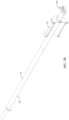
- a burner 10 for use with a direct, indirect or hybrid fired oven, e.g., a commercial/industrial oven or grill, in accordance with a first embodiment of the present invention.
- the burner 10 includes a first pipe 12 and a second pipe 14.
- the first and second pipes 12, 14 are substantially cylindrical along the length thereof, i.e., define a generally circular cross-section in a plane perpendicular to the length thereof, but the disclosure is not so limited.
- first and second pipes 12, 14 may define a non-circular cross-section, such as, for example, without limitation, a square, oval, indented, dough folded or square flattened cross-section, a combination thereof along different portions of the length of the pipe(s) or the like.
- first and second pipes 12, 14 may be differently shaped in cross-section from one another.
- one or more of the first and second pipes 12, 14 may be at least partially coated with a high emissivity thermal protective layer, e.g., a nano-emissive coating, such as, for example, as disclosed in U.S. Patent No. 8,840,942 .
- first and second pipes 12, 14 extend generally parallel with one another and are positioned along the same plane, but the invention is not so limited. In the illustrated embodiment, the first and second pipes 12, 14 are of differing lengths, but the invention is not so limited.
- the first and second pipes 12, 14 are secured relative to one another and relative to an oven chamber 1 (shown schematically in Fig. 2 ) of a direct, indirect or hybrid fired oven (not shown) via a mounting spool pipe 16 proximate a proximal end of the pipes 12 and 14.
- the mounting spool pipe 16 is generally hollow for the first and second pipes 12, 14 to extend therethrough.
- mounting plates may attach to opposing ends of the mounting spool pipe 16 and include respective apertures (not shown) for each of the first and second pipes 12, 14 to extend therethrough, but the disclosure is not so limited.
- Each aperture may be generally complementary in dimension to an outer diameter of the corresponding pipe 12, 14, for securement.
- the first and second pipes 12, 14 may also include at least one bracket 18 positioned distally of the mounting spool pipe 16 and may also be attached to the first and second pipes 12, 14 to secure their relative positioning.
- the first and second pipes 12, 14 may be secured relative to one another and to the mounting spool pipe 16 via other methods currently known or that later become known.
- the mounting spool pipe 16 extends through, and is secured to, the oven chamber wall (not shown) in a manner well understood by those of ordinary skill in the art. That is, the length of the mounting spool pipe 16 generally corresponds to the thickness of the oven chamber wall and the flanged ends 16a, 16b of the mounting spool pipe 16 are secured, e.g., fastened, to opposing sides of the wall.
- the first pipe 12 may define an operative length L, i.e., the length of the portion of the first pipe 12 extending into the oven chamber 1, between approximately 500 mm (19.6 inches) and approximately 6,100 mm (240 inches), but the disclosure is not so limited.
- the first pipe 12 defines an internal diameter D12 of between approximately 20 mm (0.75 inch IPS, i.e., iron pipe size indicating inside diameter) and approximately 50 mm (2 inches IPS).
- the first pipe 12 includes a plurality of apertures/through-holes 12a in the sidewall of the first pipe 12, e.g., laser or EDM cut, drilled or the like (shown best in Figs. 3 , 4 ), positioned in series along a portion of the length L thereof, defining the flame space of the first pipe 12.
- the plurality of apertures 12a are arranged in at least one row of apertures 12a positioned along a portion of the length L of the first pipe 12.
- the apertures 12a may be arranged in a single row of apertures 12a.
- the more than one row of apertures 12a may be employed for increased thermal output of the burner 10, such as, for example, two rows ( see Fig. 5 ).
- the respective rows may be angularly spaced from one another by between approximately 12° and approximately 15°, such as, for example, by approximately 14°.
- the apertures 12a forming one row may be axially offset, i.e., along the length of the first pipe 12, from the apertures 12a forming another row.
- the apertures 12a of one row may each be positioned between two successive apertures 12a of the adjacent row(s).
- each pair of successive apertures 12a along a row is spaced a distance X between approximately 3 mm (0.12 inch) and approximately 9 mm (0.35 inch) apart on-center, such as, for example, without limitation, approximately 5 mm (0.2 inch) apart, but the invention is not so limited.
- each aperture 12a defines an internal diameter D12a between approximately 0.02 mm (0.008 inch) and approximately 0.76 mm (0.03 inch), such as, for example, without limitation, approximately 0.4 mm (0.016 inch), but the invention is not so limited.
- the plurality of apertures 12a are positioned along a horizontal plane extending through both the first and second pipes 12, 14, on a side of the first pipe 12 facing away from the second pipe 14.
- the operative length L of the first pipe 12, the internal diameter D12 of the first pipe, the spacing X between the apertures 12a, the internal diameter D12a of the apertures 12a, and the size of the oven chamber 1, or a combination thereof determines the thermal output of the burner 10.
- the burner 10 is configured to produce between approximately 5.14 kW/m (450 Btu/in) and approximately 22.8 kW/m (2,000 Btu/in) of heat.
- the burner 10 further includes an igniter 20 (controlled via a direct spark ignition (not shown)) connected to, or mounted adjacent to, the first pipe 12 in a manner well understood by those of ordinary skill in the art and configured to provide an electrical spark adjacent one or more of the apertures 12a along the first pipe 12.
- the igniter 20 extends substantially parallel to the first pipe 12 and is positioned proximate a proximal end of the first pipe 12. In the illustrated configuration ( see Fig. 3 ), the igniter 20 is positioned in the same plane as the apertures 12a, but the invention is not so limited.
- the igniter 20 may extend through the mounting spool pipe 16 and may be secured by the mounting plates, but the invention is not so limited.
- the igniter 20 may take the form of a conventional combination igniter and flame detection sensor.
- a conventional opposite side sensor 22 may be attached to a distal end of the first pipe 12, e.g., to the bracket 18, and electrically connected to the direct spark ignition of the burner 10 in a manner well understood by those of ordinary skill in the art.
- a combination gas valve (double valved) and pressure regulator 24 e.g., without limitation, a Honeywell model number VK4105M5215 U gas control with a gas regulator, is connected to an inlet, e.g., at a proximal end, of the first pipe 12.
- the combination gas valve and pressure regulator 24 selectively fluidly connects a source of combustion fuel/gas 2 (shown schematically in Fig. 1 ) flowing from a main gas manifold (not shown) with the inlet of the first pipe 12.
- the combustion fuel/gas utilized with the first pipe 12 is hydrogen gas.
- the combination gas valve and pressure regulator 24 is configured to regulate the hydrogen gas flowing into the first pipe 12 to a pressure between approximately 5 mbar (2" wc, i.e., inches of water column) and approximately 60 mbar (24" wc).
- a combustion gas-flow nozzle 34 is fluidly interposed between the combination gas valve and pressure regulator 24 and the first pipe 12 to set the maximum amount of combustion gas entering the first pipe 12.
- the nozzle 34 is sealingly positioned within a proximal end of the first pipe 12.
- the nozzle 34 defines an inlet opening 34a and an outlet opening 34b (according to the direction of flow into the first pipe 12).
- the inner diameter of the combustion gas-flow nozzle 34 generally tapers from a wider inlet opening 34a to a narrower outlet opening 34b. The diameter of the outlet opening 34b is selected relative to the maximum amount of combustion gas required in the first pipe 12 to achieve the intended thermal output of the burner 10.
- the calibrated diameter of the outlet opening 34b determines the flow rate of the combustion gas entering the first pipe 12, i.e.., according to Bernoulli's equation.
- the outlet opening 34b of the nozzle 34 may define a diameter between approximately 0.019 inch (0.5 mm) and approximately 0.275 inch (7 mm) depending on the maximum flow rate for the particular length of the first pipe 12, such as, for example, without limitation, approximately 0.07 inch (1.8 mm).
- valves within the combination gas valve and pressure regulator 24 are opened to allow the flow of hydrogen gas from the hydrogen gas source 2 into the first pipe 12 and the pressure regulator (not shown) within the combination gas valve and pressure regulator 24 regulates the pressure of the hydrogen gas within the first pipe 12.
- the nozzle 34 sets the maximum flow rate of the hydrogen gas into the first pipe 12.
- the hydrogen gas then flows out of the apertures 12a.
- the igniter 20 is then actuated to provide the electrical spark which ignites the flame along the apertures 12a and initiates combustion of the hydrogen gas exiting from the apertures 12a.
- the hydrogen gas combusting i.e., burning, in the air within the oven chamber 1 of the oven reacts with the oxygen with the air to form moisture, i.e., water vapor, and thermal energy.
- hydrogen gas combustion byproducts are free of carbon, and, therefore, carbon emissions are significantly minimized. Additionally, water vapor byproduct of hydrogen gas combustion far exceeds that of natural gas combustion.
- the relative increase in moisture content within the oven chamber 1, in a controlled manner may aid in a baking process, such as, for example, with baking of grain-based products, e.g., bread, bagels, pretzels and the like. For example, the increase of moisture content may aid in more efficient heat transfer to the grain-based product, thereby reducing baking time.
- the increase in moisture content also enables heat to reach the inside of the product sooner, advancing functions such as yeast kill, gelatinization, and arrival time, i.e., dough becomes bread sooner.
- the moisture may subsequently be extracted (in a manner well understood by those of ordinary skill in the art) at a specific point in the baking process to allow for other objectives, such as product color and crust, to develop.
- the burner 10 advantageously utilizes a greener source of energy while also producing at least the same or better-quality products.
- the second pipe 14 defines an internal diameter D14 of between approximately 20 mm (0.75 inch IPS) and approximately 50 mm (2 inch IPS).
- the second pipe 14 may take the form of a ribbon burner, having a ribbon 26 laterally extending from, or embedded in a side wall of, the second pipe 14 along a portion of the length of the second pipe 14 in a manner well understood by those of ordinary skill in the art.
- the ribbon 26 includes a plurality of ported and/or meshed and stacked, laterally oriented ribbon strips (not shown), e.g., constructed of steel, therein (not shown), forming a lattice of apertures/channels therebetween.
- the strips generally extend the length of the ribbon 26.
- the ribbon 26 may define any internal pattern of the ported and/or meshed and stacked ribbon strips, currently known or that later becomes known. Alternatively, and as shown best in Fig.
- the second pipe 14 may include a plurality of apertures 26' formed in the sidewall of the second pipe 14 (replacing or supplementing the ribbon 26), e.g., laser or EDM cut, drilled or the like, and positioned along a portion of the length of the second pipe 14.
- the length of the ribbon 26 (or the collective span of the apertures 26') may correspond to the flame space of the first pipe 12. That is, the length of the ribbon 26 (or the collective span of the apertures 26') may be substantially equal to the portion of the first pipe 12 having the apertures 12a.
- the ribbon 26 may project in substantially the same plane as the apertures 12a.
- the second pipe 14 may be connected to an air-only source 4 (shown schematically in Fig. 1 ) via a connection fitting 14a at an inlet, e.g., at a proximal end, of the second pipe 14.
- the second pipe 14 may release between approximately 2.37 m 3 /hr (83.6 ft 3 /hr) and approximately 42.04 m 3 /hr (1,484 ft 3 /hr) of excess air into the oven chamber 1.
- the second pipe 14, releasing only air (via the ribbons 26 or the apertures 26'), may be employed to assist in reduction of nitrogen oxides. That is, the second pipe 14, positioned on an opposite side of the first pipe 12 from the apertures 12a, may release air to substantially envelope the first pipe 12.
- Nitrogen oxides are generally produced from the reaction of nitrogen and oxygen gases in the air during combustion, especially at high temperatures.
- release of air from the second pipe 14 may assist in cooling the flame along the apertures 12a, thereby reducing nitrogen oxide formation. Release of air from the second pipe 14 may also assist with the hydrogen gas combustion process, e.g., maintaining an appropriate volume of air within the oven chamber 1.
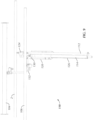
- Figs. 8-10 illustrate a second embodiment of a burner for use with a direct, indirect or hybrid fired oven.
- the reference numerals of the second embodiment are distinguishable from those of the above-described first embodiment by a factor of one hundred (100), but otherwise indicate the same elements as indicated above, except as otherwise specified.
- the burner 110 of the present embodiment is similar to that of the earlier embodiment. Therefore, the description of certain similarities and modes of operation between the embodiments may be omitted herein for the sake of brevity and convenience, and, therefore, is not limiting.
- a primary difference of the burner 110 over the burner 10 is the selective operability of the second pipe 114 as a fuel gas burner.
- the fuel gas operating as the energy source for the second pipe 114 may take the form of, for example, natural gas, a mixed blend of natural gas and hydrogen gas, propane or a mixed blend of propane and hydrogen gas.
- propane or a mixed blend of propane and hydrogen gas may be used as the fuel gas for the second pipe 114, but the second pipe 114 may equally be operable with other fuel gases, such as, for example, the other fuel gasses previously identified.
- the second pipe 114 is oriented such that the ribbon 126 faces away from the first pipe 112. That is, second pipe 114 is rotated substantially 180° from the second pipe 14 of Figs. 1-7B .
- the burner assembly 110 includes a second igniter 128 (controlled via a direct spark ignition (not shown)) connected to, or positioned adjacent, the ribbon 126 of the second pipe 114 in a manner well understood by those of ordinary skill in the art and configured to provide an electrical spark to the ribbon 126.
- the second igniter 128 extends substantially parallel to the second pipe 112 and is positioned proximate a proximal end of the second pipe 114.
- the second igniter 128 is positioned in the same plane as the ribbon 126, but the disclosure is not so limited. Similarly to the first and second pipes 112, 114, the second igniter 128 may extend through the mounting spool pipe (not shown) and may be secured by the mounting plates (not shown), but the disclosure is not so limited. As should be understood by those of ordinary skill in the art, the second igniter 128 may also take the form of a conventional combination igniter and flame detection sensor.
- a mixing valve 130 is connected to an inlet, e.g., at a proximal end, of the second pipe 114.
- the mixing valve 130 is fluidly connected with a source of air 104 (via air inlet 130a - see Fig. 10 ) and with a source of natural gas, or a natural gas and hydrogen gas blend, 106 (via gas inlet 130b - see Fig. 10 ).
- Natural gas and hydrogen gas may be premixed, for example, into a blend having between approximately 10% and approximately 70% hydrogen gas (i.e., the remaining percentage being natural gas), such as, for example, without limitation, approximately 50% hydrogen gas.
- the mixing valve 130 mixes the air and natural gas (or air and natural gas/hydrogen gas blend) together according to a predetermined ratio (of air to natural gas according to the percentage of natural gas present) and fluidly connects the mixed air and natural gas (or mixed air and natural gas/hydrogen gas blend) with the second pipe 114 in a manner well understood by those of ordinary skill in the art.
- a combination valve and zero-pressure regulator 132 e.g., without limitation a Honeywell model number VK4125V2029 C series combination valve, zero regulator, and ignition system, may be employed in line between the source of natural gas (or natural gas/hydrogen gas blend) 106 and the mixing valve 130.
- the gas valves within the combination gas valve and zero-pressure regulator 132 regulate, i.e., selectively permit or prohibit, the flow of natural gas (or natural gas/hydrogen gas blend) from the natural gas (or natural gas/hydrogen gas blend) source 106 to the mixing valve 130.
- the zero-pressure regulator within the combination gas valve and zero-pressure regulator 132 selectively allows the flow of natural gas (or natural gas/hydrogen gas blend) from the natural gas (or natural gas/hydrogen gas blend) source 106, through the combination gas valve and zero-pressure regulator 132, and to the gas inlet 130b of the mixing valve 130 upon generation of a venturi ( see Fig. 10 ), i.e., a vacuum, created by the flow of air through the mixing valve 130 via the air inlet 130a.
- a venturi see Fig. 10
- the air inlet 130a of the mixing valve 130 may include (therein, or adjacent thereto, and upstream of or proximate to the gas inlet 130b) an airflow nozzle 136 therein, to set the maximum amount of air mixing with the natural gas (or natural gas/hydrogen gas blend) and subsequently entering the second pipe 114.
- the nozzle 136 defines an inlet opening 136a and an outlet opening 136b (according to the direction of flow into the second pipe 114).
- the inner diameter of the airflow nozzle 136 generally tapers from a wider inlet opening 136a to a narrower outlet opening 136b.
- the diameter of the outlet opening 136b is selected relative to the maximum amount of air required to mix with natural gas (or natural gas/hydrogen gas blend) and enter into the second pipe 114 to achieve the intended thermal output of the burner 110 when operated as a natural gas (or natural gas/hydrogen gas blend) burner.
- the calibrated diameter of the outlet opening 136b in combination with the pressure of the air, determines the flow rate of the subsequently mixed air and natural gas (or natural gas/hydrogen gas blend) entering the second pipe 114, i.e.., according to Bernoulli's equation.
- the outlet opening 136b of the nozzle 136 may define a diameter between approximately 0.118 inch (3 mm) and approximately 0.98 inch (25 mm) depending on the maximum flow rate for the particular length of the second pipe 114, such as, for example, without limitation, approximately 0.196 inch (5 mm).
- the second pipe 114 may be selectively rotatable e.g., manually or through an automated process, about a central axis thereof, such that the ribbon 126 may be selectively oriented as shown in Figs. 8 , 9 or as shown in Figs. 1-3 and 7A .
- This allows an oven to be readily converted between a hydrogen burner oven and a natural gas (or natural gas/hydrogen gas blend) burner oven.
- a natural gas or natural gas/hydrogen gas blend
- the oven could be quickly converted over to natural gas (or natural gas/hydrogen gas blend) oven.
- a second example is if there is no hydrogen supply available when the oven is initially built, but it is expected to be available in the future. The oven could be initially set to burn natural gas and then switched over to hydrogen gas when the hydrogen becomes available.
- the first pipe 112 of the burner 110 may be selectively operated as a hydrogen gas burner as previously described with respect to the burner 10.
- the second pipe 114 may be rotated such that the ribbon 126 faces the first pipe 112 (like the second pipe 14), and the second pipe 114 may receive only air and operate as previously described with respect to the second pipe 14 of the embodiment of Figs. 1-7B .
- the gas valves within the combination gas valve and zero-pressure regulator 132 may be closed to prohibit the flow of natural gas (or a natural gas/hydrogen gas blend) to the second pipe 114, such that only air from the air source 104 may be delivered to the second pipe 114 (via the mixing valve 130).
- the second pipe 114 may then be operated to release air to substantially envelope the first pipe 112 during operation of the first pipe 112 as a hydrogen gas burner and to maintain an appropriate volume of air within the oven chamber.
- the second pipe 114 may also be selectively operated as a natural gas (or a natural gas/hydrogen gas blend) burner, e.g., in the absence or reduced availability of hydrogen gas.
- the second pipe 114 may be rotated such that the ribbon 126 faces away from the first pipe 112 (as shown in Figs. 8 , 9 ).
- the gas valve(s) (not shown) within the combination gas valve and pressure regulator 124 may be closed, preventing gas from flowing into the first pipe 112.
- the second pipe 114 may then be operated as a natural gas (or natural gas/hydrogen gas blend) burner in a manner well understood by those of ordinary skill in the art.
- the mixing valve 130 mixes the air and natural gas (or natural gas/hydrogen gas blend) together according to a predetermined ratio or air to natural gas and fluidly connects the mixed air and natural gas (or air and natural gas/hydrogen gas blend) with the second pipe 114.
- the mixed air and natural gas (or air and natural gas/hydrogen gas blend) then flows out of the second pipe 114 through the ribbon 126 and ignited by the second igniter 128 to light a flame.
- the second pipe 114 may be fluidly connected with the aforementioned upstream components via flexible conduits, hoses, swivel union or the like, in order to permit simplified rotation of the second pipe 114.
Landscapes
- Engineering & Computer Science (AREA)
- Chemical & Material Sciences (AREA)
- Combustion & Propulsion (AREA)
- Mechanical Engineering (AREA)
- General Engineering & Computer Science (AREA)
- Gas Burners (AREA)
Claims (17)
- Un brûleur (10, 110) à gaz hydrogène, comprenant :un premier tuyau (12, 112) apte à être étendu dans une chambre de four (1), le premier tuyau (12, 112) comprenant une pluralité de trous traversants (12a) dans une paroi latérale de lui-même et le long d'une partie de sa longueur, faisant communiquer de manière fluidique l'intérieur du premier tuyau (12, 112) avec l'extérieur de celui-ci ;une combinaison de vanne de gaz et de régulateur de pression (24, 124) reliée à une entrée du premier tuyau (12, 112), la combinaison de vanne de gaz et de régulateur de pression (24, 124) étant configurée de façon à relier fluidiquement une source (2) d'hydrogène gazeux avec l'intérieur du premier tuyau (12, 112) à une pression prédéterminée, de telle sorte que l'hydrogène gazeux s'écoule dans le premier tuyau (12, 112) depuis son entrée et sort du premier tuyau (12, 112) à travers la pluralité de trous traversants (12a) ;un allumeur (20) configuré pour fournir une étincelle électrique adjacente à au moins un trou de la pluralité de trous traversants (12a), et, à son tour, allumer et initier la combustion de l'hydrogène gazeux sortant de la pluralité de trous traversants (12a) ; etun deuxième tuyau (14, 114) apte à s'étendre dans la chambre du four (1), le deuxième tuyau (14, 114) ayant une pluralité d'ouvertures (26, 26', 126) le long d'une partie d'une longueur d'une paroi latérale de lui-même et faisant communiquer de manière fluidique l'intérieur du deuxième tuyau (14, 114) avec l'extérieur de celui-ci, le deuxième tuyau (14, 114) étant configuré pour, au niveau de son entrée, être relié fluidiquement à une source d'air (4, 104), de telle sorte que l'air s'écoule dans le deuxième tuyau (14, 114) depuis son entrée et sorte du deuxième tuyau (14, 114) à travers les ouvertures (26, 26', 126).
- Le brûleur (10, 110) selon la revendication 1, dans lequel le deuxième tuyau (14, 114) est positionné sur un côté opposé du premier tuyau (12, 112) par rapport à la pluralité de trous traversants (12a), et les ouvertures (26, 26', 126) sont tournées vers le premier tuyau (12, 112).
- Le brûleur (10, 110) selon la revendication 1 ou la revendication 2, dans lequel les ouvertures (26, 26', 126) sont coplanaires avec la pluralité de trous traversants (12a).
- Le brûleur (10, 110) selon l'une quelconque des revendications précédentes, dans lequel les ouvertures (26, 26', 126) s'étendent sur une longueur sensiblement égale à la partie de la longueur du premier tuyau (12, 112) ayant la pluralité de trous traversants (12a).
- Le brûleur (10, 110) selon l'une quelconque des revendications précédentes, dans lequel le deuxième tuyau (14, 114) comprend un ruban (26, 126) le long de la partie de la longueur de sa paroi latérale, le ruban (26, 126) définissant les ouvertures (26, 26', 126).
- Un brûleur à gaz (110) comprenant :un premier tuyau (12, 112) apte à être étendu dans une chambre de four (1), le premier tuyau (12, 112) comprenant une pluralité de trous traversants (12a) dans une paroi latérale de lui-même et le long d'une partie de sa longueur, faisant communiquer de manière fluidique l'intérieur du premier tuyau (12, 112) avec l'extérieur de celui-ci ;une combinaison de vanne de gaz et de régulateur de pression (24, 124) reliée à une entrée du premier tuyau (12, 112), la combinaison de vanne de gaz et de régulateur de pression (24, 124) étant configurée de façon à relier sélectivement et fluidiquement une source (2) d'hydrogène gazeux avec l'intérieur du premier tuyau (12, 112) à une pression prédéterminée pour permettre sélectivement à l'hydrogène gazeux de s'écouler dans le premier tuyau (12, 112) depuis son entrée, et de sortir du premier tuyau (12, 112) à travers la pluralité de trous traversants (12a) ;un premier allumeur (20) configuré pour fournir sélectivement une étincelle électrique adjacente à au moins un trou de la pluralité de trous traversants (12a), et, à son tour, allumer sélectivement et initier la combustion de l'hydrogène gazeux sortant de la pluralité de trous traversants (12a) ;un deuxième tuyau (114) apte à être étendu dans la chambre du four (1), le deuxième tuyau (114) ayant un ruban (126) s'étendant le long d'une partie de sa longueur et faisant communiquer de manière fluidique l'intérieur du deuxième tuyau (114) avec l'extérieur de celui-ci,une vanne mélangeuse (130) reliée à une entrée du deuxième tuyau (114), la vanne mélangeuse (130) étant configurée pour recevoir de l'air provenant d'une source d'air (104), recevoir sélectivement un gaz combustible provenant d'une source (106) de gaz combustible, mélanger sélectivement l'air et le gaz combustible ensemble et, de manière sélective, relier fluidiquement le mélange d'air et de gaz combustible avec l'intérieur du deuxième tuyau (114), de telle sorte que l'air mélangé et le gaz combustible s'écoulent dans le deuxième tuyau (114) depuis son entrée et sortent du deuxième tuyau (114) à travers le ruban (126) ; etun deuxième allumeur (128) configuré pour fournir sélectivement une étincelle électrique adjacente au ruban (126) et, à son tour, allumer sélectivement et initier la combustion du mélange d'air et de gaz combustible sortant du ruban (126).
- Le brûleur (110) selon la revendication 6, dans lequel le deuxième tuyau (114) est positionné sur un côté opposé du premier tuyau (12, 112) par rapport à la pluralité de trous traversants (12a), et le ruban (126) est tourné à l'opposé du premier tuyau (12, 112).
- Le brûleur (110) selon la revendication 6 ou la revendication 7, comprenant en outre une combinaison d'une vanne de gaz et d'un régulateur de pression nulle (132) en communication fluidique avec une entrée (130b) de la vanne mélangeuse (130), la combinaison de vanne de gaz et de régulateur à pression nulle (132) étant configurée pour, sélectivement, autoriser ou interdire l'écoulement du gaz combustible depuis la source (106) du gaz combustible vers la vanne mélangeuse (130).
- Un brûleur à gaz (110) comprenant :un premier tuyau (112) apte à être étendu dans une chambre de four (1), le premier tuyau (112) comprenant une pluralité de trous traversants (12a) dans une paroi latérale de lui-même et le long d'une partie d'une longueur de lui-même, faisant communiquer de manière fluidique l'intérieur du premier tuyau (112) avec l'extérieur de celui-ci ;une combinaison de vanne de gaz et de régulateur de pression (124) reliée à une entrée du premier tuyau (112), la combinaison de vanne de gaz et de régulateur de pression (124) étant configurée de façon à relier fluidiquement, de manière sélective, une source (2) d'hydrogène gazeux avec l'intérieur du premier tuyau (112) à une pression prédéterminée afin de permettre sélectivement à l'hydrogène gazeux de s'écouler dans le premier tuyau (112) à partir de l'entrée de celui-ci, et de sortir du premier tuyau (112) à travers la pluralité de trous traversants (12a) ;un premier allumeur (20) configuré pour fournir sélectivement une étincelle électrique adjacente à au moins un trou de la pluralité de trous traversants (12a), et, à son tour, allumer sélectivement et initier la combustion de l'hydrogène gazeux sortant de la pluralité de trous traversants (12a) ;un deuxième tuyau (114) apte à être étendu dans la chambre du four (1), le deuxième tuyau (114) ayant un ruban (126) s'étendant le long d'une partie d'une longueur de celui-ci et faisant communiquer fluidiquement l'intérieur du deuxième tuyau (114) avec l'extérieur de celui-ci, le deuxième tuyau (114) étant apte à tourner autour de son axe central entre une première position et une deuxième position, le ruban (126), dans la première position, étant tourné vers le premier tuyau (112), et, dans la deuxième position, le ruban (126) étant orienté à l'opposé du premier tuyau (112) ;une vanne mélangeuse (130) reliée à une entrée du deuxième tuyau (114), la vanne mélangeuse (130) étant configurée pour recevoir de l'air provenant d'une source d'air (104) dans la première position du deuxième tuyau (114) et pour relier de manière fluidique l'air avec l'intérieur du deuxième tuyau (114), de telle sorte que l'air s'écoule dans le deuxième tuyau (114) depuis son entrée et sorte du deuxième tuyau (114) à travers le ruban (126), et la vanne mélangeuse (130) étant configurée de façon à recevoir de l'air provenant de la source d'air (104) et recevoir un gaz combustible provenant d'une source (106) de gaz combustible dans la deuxième position du deuxième tuyau (114), mélanger l'air et le carburant gaz ensemble et diriger le mélange d'air et de gaz combustible vers l'intérieur du deuxième tuyau (114) de telle sorte que le mélange d'air et de gaz combustible s'écoule dans le deuxième tuyau (114) depuis son entrée et sorte du deuxième tuyau (114) à travers le ruban (126) ; etun deuxième allumeur (128) configuré pour fournir une étincelle électrique adjacente au ruban (126) dans la deuxième position du deuxième tuyau (114), et, à son tour, allumer sélectivement et initier la combustion du mélange d'air et de gaz combustible sortant du ruban (126).
- Le brûleur (110) selon la revendication 9, dans lequel le deuxième tuyau (114) est positionné sur un côté opposé du premier tuyau (112) par rapport à la pluralité de trous traversants (12a).
- Le brûleur (110) selon la revendication 9 ou la revendication 10, comprenant en outre une combinaison d'une vanne de gaz et d'un régulateur de pression nulle (132) en communication fluidique avec une entrée (130b) de la vanne mélangeuse (130), la combinaison de vanne de gaz et de régulateur à pression nulle (132) étant configurée de façon à interdire l'écoulement du gaz combustible depuis la source (106) du gaz combustible vers la vanne mélangeuse (130) dans la première position du deuxième tuyau (114) et étant configurée de façon à permettre l'écoulement du gaz combustible depuis la source (106) du gaz combustible jusqu'à la vanne mélangeuse (130) dans la deuxième position du deuxième tuyau (114).
- Le brûleur (110) selon l'une quelconque des revendications 6 à 11, dans lequel le ruban (126) a une longueur sensiblement égale à la partie de la longueur du premier tuyau (112) comportant la pluralité de trous traversants (12a).
- Le brûleur (110) selon l'une quelconque des revendications 6 à 12, dans lequel le gaz combustible comprend du gaz naturel, un mélange mixte de gaz naturel et d'hydrogène gazeux, du propane ou un mélange mixte de propane et d'hydrogène gazeux.
- Le brûleur (110) selon l'une quelconque des revendications précédentes, dans lequel le premier tuyau (112) et le deuxième tuyau (114) sont coplanaires et s'étendent parallèlement l'un à l'autre.
- Le brûleur (110) selon l'une quelconque des revendications précédentes, dans lequel au moins l'un parmi le premier tuyau (112) et le deuxième tuyau (114) est sensiblement cylindrique.
- Le brûleur (110) selon l'une quelconque des revendications précédentes, dans lequel les trous traversants de la pluralité de trous traversants (12a) sont agencés en au moins une rangée le long de la partie de la longueur du premier tuyau (112).
- Le brûleur (110) selon l'une quelconque des revendications précédentes, dans lequel les trous traversants de la pluralité de trous traversants (12a) sont agencés en une seule rangée le long de la partie de la longueur du premier tuyau (112).
Applications Claiming Priority (2)
| Application Number | Priority Date | Filing Date | Title |
|---|---|---|---|
| US202063045359P | 2020-06-29 | 2020-06-29 | |
| PCT/IB2021/055779 WO2022003546A1 (fr) | 2020-06-29 | 2021-06-29 | Brûleur à gaz hydrogène |
Publications (3)
| Publication Number | Publication Date |
|---|---|
| EP4158247A1 EP4158247A1 (fr) | 2023-04-05 |
| EP4158247C0 EP4158247C0 (fr) | 2023-11-01 |
| EP4158247B1 true EP4158247B1 (fr) | 2023-11-01 |
Family
ID=76797037
Family Applications (1)
| Application Number | Title | Priority Date | Filing Date |
|---|---|---|---|
| EP21737790.2A Active EP4158247B1 (fr) | 2020-06-29 | 2021-06-29 | Brûleur à gaz hydrogène |
Country Status (4)
| Country | Link |
|---|---|
| US (1) | US11428405B2 (fr) |
| EP (1) | EP4158247B1 (fr) |
| ES (1) | ES2965476T3 (fr) |
| WO (1) | WO2022003546A1 (fr) |
Families Citing this family (8)
| Publication number | Priority date | Publication date | Assignee | Title |
|---|---|---|---|---|
| CA3096285A1 (fr) | 2020-10-16 | 2022-04-16 | Pulsemedica Corp. | Dispositif, systeme et methodes d'administration de laser et d'imagerie ophtalmologique |
| CA3103872A1 (en) * | 2020-12-23 | 2022-06-23 | Pulsemedica Corp. | Automatic annotation of condition features in medical images |
| US12474057B2 (en) * | 2022-06-03 | 2025-11-18 | Flynn Burner Corporation | Electric burner |
| US11867400B1 (en) * | 2023-02-02 | 2024-01-09 | Pratt & Whitney Canada Corp. | Combustor with fuel plenum with mixing passages having baffles |
| CN116085825B (zh) * | 2023-03-09 | 2026-05-05 | 中国空气动力研究与发展中心空天技术研究所 | 一种互击式空气氢气火炬点火器 |
| WO2025041081A1 (fr) * | 2023-08-23 | 2025-02-27 | AMF Den Boer B.V. | Brûleur à hydrogène gazeux |
| WO2025235835A1 (fr) * | 2024-05-10 | 2025-11-13 | Stolle Machinery Company, Llc | Système de fabrication de canettes comprenant un four infrarouge à hydrogène et un système de recyclage d'eau |
| NL2038265B1 (en) * | 2024-07-18 | 2026-02-05 | Bngs Beheer B V | A hybrid heater for heating an oven, an oven comprising the hybrid heater, a method for operating the hybrid heater |
Family Cites Families (33)
| Publication number | Priority date | Publication date | Assignee | Title |
|---|---|---|---|---|
| US1916983A (en) * | 1933-07-04 | Gas bubneb | ||
| US2294748A (en) | 1940-07-24 | 1942-09-01 | C M Kemp Mfg Company | Ribbon flame burner |
| US2494243A (en) | 1944-07-31 | 1950-01-10 | Louis D Houlis | Pressure ribbon-type gas burner |
| US2707519A (en) * | 1949-04-28 | 1955-05-03 | Robertshaw Fulton Controls Co | Automatic pilot and ignition systems for fuel burner |
| US3172460A (en) | 1961-11-24 | 1965-03-09 | Baker Perkins Inc | Ribbon burner assembly |
| US4421474A (en) | 1982-08-25 | 1983-12-20 | Meyer Stanley A | Hydrogen gas burner |
| US4465455A (en) | 1982-09-24 | 1984-08-14 | Meyer Stanley A | Start-up/shut-down for a hydrogen gas burner |
| US4702693A (en) * | 1986-12-03 | 1987-10-27 | Joseph Fraioli | Gas-fired infrared heater |
| US5435343A (en) | 1994-03-01 | 1995-07-25 | Honeywell Inc. | Two stage natural/LP gas convertible pressure regulator valve with single servo controller |
| DE19515286C2 (de) | 1995-04-26 | 1998-07-02 | Honeywell Bv | Druckregler zum Erzeugen eines geregelten Steuerdrucks für ein membrangesteuertes Gasventil |
| US6267585B1 (en) | 1995-12-19 | 2001-07-31 | Daimlerchrysler Aerospace Airbus Gmbh | Method and combustor for combusting hydrogen |
| US6302143B1 (en) | 1999-09-17 | 2001-10-16 | Honeywell International Inc. | Two-stage servo gas pressure regulator module |
| US6705307B2 (en) | 2002-05-15 | 2004-03-16 | Weber-Stephens Product Co. | Removable gas burner unit for barbecue grill |
| DE102004033545B4 (de) | 2004-07-09 | 2006-06-14 | J. Eberspächer GmbH & Co. KG | Brenner |
| US20060032930A1 (en) * | 2004-08-13 | 2006-02-16 | Banner Engineering & Sales, Inc. | Methods and apparatus for controlling baking oven zone temperature |
| CN101495811A (zh) | 2006-05-01 | 2009-07-29 | 克罗普利控股有限公司 | 使用由电解槽生产的可燃气体烹饪的方法和设备 |
| US8757139B2 (en) | 2009-06-29 | 2014-06-24 | David Deng | Dual fuel heating system and air shutter |
| FR2913097B1 (fr) | 2007-02-26 | 2009-04-24 | Inst Francais Du Petrole | Bruleur poreux a hydrogene sans premelange |
| US8663448B2 (en) | 2008-01-04 | 2014-03-04 | H2 Pump, Llc | Hydrogen furnace system and method |
| EP2299178B1 (fr) | 2009-09-17 | 2015-11-04 | Alstom Technology Ltd | Procédé et système de combustion de turbine à gaz pour mélanger sans danger des carburants riches en H2 avec de l'air |
| WO2011062513A1 (fr) | 2009-11-18 | 2011-05-26 | Chung Dominic N Jr | Cuisinière utilisant l'électrolyse pour produire de l'hydrogène |
| US8840942B2 (en) | 2010-09-24 | 2014-09-23 | Emisshield, Inc. | Food product and method and apparatus for baking |
| WO2012143738A2 (fr) | 2011-04-21 | 2012-10-26 | Itm Power (Research) Limited | Système de brûleur |
| KR101974819B1 (ko) | 2011-08-17 | 2019-08-23 | 다이요 닛산 가부시키가이샤 | H2용 버너 및 h2용 버너의 연소 방법 |
| US20150245741A1 (en) * | 2014-03-03 | 2015-09-03 | Aaron Fechter | Grill System and Process |
| US12276420B2 (en) | 2016-02-03 | 2025-04-15 | Strong Force Iot Portfolio 2016, Llc | Industrial internet of things smart heating systems and methods that produce and use hydrogen fuel |
| WO2017136489A1 (fr) | 2016-02-03 | 2017-08-10 | Caspo, Llc | Système de cuisson intelligent qui produit et utilise un combustible à base d'hydrogène |
| US10422530B2 (en) | 2016-10-27 | 2019-09-24 | Reecon M & E Co. Ltd. | Smart fuel burning system and method of operating same |
| JP6551375B2 (ja) | 2016-12-07 | 2019-07-31 | トヨタ自動車株式会社 | 水素ガスバーナ構造およびこれを備えた水素ガスバーナ装置 |
| JP6597662B2 (ja) | 2017-02-08 | 2019-10-30 | トヨタ自動車株式会社 | 水素ガスバーナ装置 |
| TR201707067A2 (tr) | 2017-05-13 | 2017-12-21 | Murat Akdemir | Hi̇drojen yakitli yemek pi̇şi̇rme firini |
| JP6940338B2 (ja) | 2017-09-04 | 2021-09-29 | トヨタ自動車株式会社 | 水素ガスバーナー装置用のノズル構造体 |
| JP6863189B2 (ja) | 2017-09-05 | 2021-04-21 | トヨタ自動車株式会社 | 水素ガスバーナー装置用のノズル構造体 |
-
2021
- 2021-06-29 US US17/361,367 patent/US11428405B2/en active Active
- 2021-06-29 WO PCT/IB2021/055779 patent/WO2022003546A1/fr not_active Ceased
- 2021-06-29 EP EP21737790.2A patent/EP4158247B1/fr active Active
- 2021-06-29 ES ES21737790T patent/ES2965476T3/es active Active
Also Published As
| Publication number | Publication date |
|---|---|
| US20210404655A1 (en) | 2021-12-30 |
| US11428405B2 (en) | 2022-08-30 |
| EP4158247C0 (fr) | 2023-11-01 |
| WO2022003546A1 (fr) | 2022-01-06 |
| EP4158247A1 (fr) | 2023-04-05 |
| ES2965476T3 (es) | 2024-04-15 |
Similar Documents
| Publication | Publication Date | Title |
|---|---|---|
| US11428405B2 (en) | Hydrogen gas burner | |
| US6786717B2 (en) | Combustion apparatus | |
| US5937796A (en) | Gas apparatus for heating fluids | |
| EP0017429B1 (fr) | Brûleur à formation réduite de NOX | |
| JP2597793B2 (ja) | 燃料段階式の予混合低NOx燃焼器 | |
| US5458484A (en) | Pre-mix flame type burner | |
| JP4540263B2 (ja) | 液状及びガス状燃料を燃焼する低窒素酸化物装置及び方法。 | |
| KR20180126551A (ko) | 패널 연료 분사기를 갖는 연소 시스템 | |
| WO2005052446A1 (fr) | Bruleur a gaz a faibles emissions de polluants | |
| US10006628B2 (en) | Low NOx gas burners with carryover ignition | |
| EP3647660B1 (fr) | Brûleur à prémélange et unité de traitement thermique pour plaque métallique | |
| EP0200626B1 (fr) | Brûleur à air soufflé et four de boulanger le contenant | |
| CN109611842A (zh) | 超低氮排放燃气燃烧器 | |
| US20250067430A1 (en) | Hydrogen gas burner | |
| CN114838353B (zh) | 燃烧器及燃气灶 | |
| USRE33374E (en) | Forced air/gas burner and baking oven incorporating same | |
| JP2002235904A (ja) | ガス燃焼用バーナー、それを備えたガスオーブン及び燃焼ガス中の一酸化炭素の量を低減する方法 | |
| CN222480484U (zh) | 燃气燃烧器及烘烤设备 | |
| CN217684980U (zh) | 炉头及燃烧器 | |
| CN222911641U (zh) | 燃烧器、燃气灶和集成电器 | |
| CN222911656U (zh) | 火盖、燃烧器、燃气灶和集成电器 | |
| CN115234913B (zh) | 气体分配装置、燃烧器、热水器及热水器的控制方法 | |
| JP2718895B2 (ja) | ガス焼成装置 | |
| CN108458363A (zh) | 蓄热式燃烧器装置 | |
| JP2008202925A (ja) | ガス焼成装置 |
Legal Events
| Date | Code | Title | Description |
|---|---|---|---|
| STAA | Information on the status of an ep patent application or granted ep patent |
Free format text: STATUS: UNKNOWN |
|
| STAA | Information on the status of an ep patent application or granted ep patent |
Free format text: STATUS: THE INTERNATIONAL PUBLICATION HAS BEEN MADE |
|
| PUAI | Public reference made under article 153(3) epc to a published international application that has entered the european phase |
Free format text: ORIGINAL CODE: 0009012 |
|
| STAA | Information on the status of an ep patent application or granted ep patent |
Free format text: STATUS: REQUEST FOR EXAMINATION WAS MADE |
|
| 17P | Request for examination filed |
Effective date: 20220902 |
|
| AK | Designated contracting states |
Kind code of ref document: A1 Designated state(s): AL AT BE BG CH CY CZ DE DK EE ES FI FR GB GR HR HU IE IS IT LI LT LU LV MC MK MT NL NO PL PT RO RS SE SI SK SM TR |
|
| GRAP | Despatch of communication of intention to grant a patent |
Free format text: ORIGINAL CODE: EPIDOSNIGR1 |
|
| STAA | Information on the status of an ep patent application or granted ep patent |
Free format text: STATUS: GRANT OF PATENT IS INTENDED |
|
| DAV | Request for validation of the european patent (deleted) | ||
| DAX | Request for extension of the european patent (deleted) | ||
| INTG | Intention to grant announced |
Effective date: 20230515 |
|
| GRAS | Grant fee paid |
Free format text: ORIGINAL CODE: EPIDOSNIGR3 |
|
| GRAA | (expected) grant |
Free format text: ORIGINAL CODE: 0009210 |
|
| STAA | Information on the status of an ep patent application or granted ep patent |
Free format text: STATUS: THE PATENT HAS BEEN GRANTED |
|
| AK | Designated contracting states |
Kind code of ref document: B1 Designated state(s): AL AT BE BG CH CY CZ DE DK EE ES FI FR GB GR HR HU IE IS IT LI LT LU LV MC MK MT NL NO PL PT RO RS SE SI SK SM TR |
|
| REG | Reference to a national code |
Ref country code: GB Ref legal event code: FG4D |
|
| REG | Reference to a national code |
Ref country code: CH Ref legal event code: EP |
|
| REG | Reference to a national code |
Ref country code: DE Ref legal event code: R096 Ref document number: 602021006478 Country of ref document: DE |
|
| REG | Reference to a national code |
Ref country code: IE Ref legal event code: FG4D |
|
| U01 | Request for unitary effect filed |
Effective date: 20231130 |
|
| U07 | Unitary effect registered |
Designated state(s): AT BE BG DE DK EE FI FR IT LT LU LV MT NL PT SE SI Effective date: 20231207 |
|
| PG25 | Lapsed in a contracting state [announced via postgrant information from national office to epo] |
Ref country code: GR Free format text: LAPSE BECAUSE OF FAILURE TO SUBMIT A TRANSLATION OF THE DESCRIPTION OR TO PAY THE FEE WITHIN THE PRESCRIBED TIME-LIMIT Effective date: 20240202 |
|
| PG25 | Lapsed in a contracting state [announced via postgrant information from national office to epo] |
Ref country code: IS Free format text: LAPSE BECAUSE OF FAILURE TO SUBMIT A TRANSLATION OF THE DESCRIPTION OR TO PAY THE FEE WITHIN THE PRESCRIBED TIME-LIMIT Effective date: 20240301 |
|
| REG | Reference to a national code |
Ref country code: ES Ref legal event code: FG2A Ref document number: 2965476 Country of ref document: ES Kind code of ref document: T3 Effective date: 20240415 |
|
| PG25 | Lapsed in a contracting state [announced via postgrant information from national office to epo] |
Ref country code: IS Free format text: LAPSE BECAUSE OF FAILURE TO SUBMIT A TRANSLATION OF THE DESCRIPTION OR TO PAY THE FEE WITHIN THE PRESCRIBED TIME-LIMIT Effective date: 20240301 Ref country code: GR Free format text: LAPSE BECAUSE OF FAILURE TO SUBMIT A TRANSLATION OF THE DESCRIPTION OR TO PAY THE FEE WITHIN THE PRESCRIBED TIME-LIMIT Effective date: 20240202 |
|
| PG25 | Lapsed in a contracting state [announced via postgrant information from national office to epo] |
Ref country code: RS Free format text: LAPSE BECAUSE OF FAILURE TO SUBMIT A TRANSLATION OF THE DESCRIPTION OR TO PAY THE FEE WITHIN THE PRESCRIBED TIME-LIMIT Effective date: 20231101 Ref country code: PL Free format text: LAPSE BECAUSE OF FAILURE TO SUBMIT A TRANSLATION OF THE DESCRIPTION OR TO PAY THE FEE WITHIN THE PRESCRIBED TIME-LIMIT Effective date: 20231101 Ref country code: NO Free format text: LAPSE BECAUSE OF FAILURE TO SUBMIT A TRANSLATION OF THE DESCRIPTION OR TO PAY THE FEE WITHIN THE PRESCRIBED TIME-LIMIT Effective date: 20240201 Ref country code: HR Free format text: LAPSE BECAUSE OF FAILURE TO SUBMIT A TRANSLATION OF THE DESCRIPTION OR TO PAY THE FEE WITHIN THE PRESCRIBED TIME-LIMIT Effective date: 20231101 |
|
| PG25 | Lapsed in a contracting state [announced via postgrant information from national office to epo] |
Ref country code: CZ Free format text: LAPSE BECAUSE OF FAILURE TO SUBMIT A TRANSLATION OF THE DESCRIPTION OR TO PAY THE FEE WITHIN THE PRESCRIBED TIME-LIMIT Effective date: 20231101 |
|
| PG25 | Lapsed in a contracting state [announced via postgrant information from national office to epo] |
Ref country code: SK Free format text: LAPSE BECAUSE OF FAILURE TO SUBMIT A TRANSLATION OF THE DESCRIPTION OR TO PAY THE FEE WITHIN THE PRESCRIBED TIME-LIMIT Effective date: 20231101 |
|
| PG25 | Lapsed in a contracting state [announced via postgrant information from national office to epo] |
Ref country code: SM Free format text: LAPSE BECAUSE OF FAILURE TO SUBMIT A TRANSLATION OF THE DESCRIPTION OR TO PAY THE FEE WITHIN THE PRESCRIBED TIME-LIMIT Effective date: 20231101 Ref country code: SK Free format text: LAPSE BECAUSE OF FAILURE TO SUBMIT A TRANSLATION OF THE DESCRIPTION OR TO PAY THE FEE WITHIN THE PRESCRIBED TIME-LIMIT Effective date: 20231101 Ref country code: CZ Free format text: LAPSE BECAUSE OF FAILURE TO SUBMIT A TRANSLATION OF THE DESCRIPTION OR TO PAY THE FEE WITHIN THE PRESCRIBED TIME-LIMIT Effective date: 20231101 |
|
| REG | Reference to a national code |
Ref country code: DE Ref legal event code: R097 Ref document number: 602021006478 Country of ref document: DE |
|
| PLBE | No opposition filed within time limit |
Free format text: ORIGINAL CODE: 0009261 |
|
| STAA | Information on the status of an ep patent application or granted ep patent |
Free format text: STATUS: NO OPPOSITION FILED WITHIN TIME LIMIT |
|
| U21 | Renewal fee for the european patent with unitary effect paid with additional fee |
Year of fee payment: 4 Effective date: 20240827 |
|
| 26N | No opposition filed |
Effective date: 20240802 |
|
| PG25 | Lapsed in a contracting state [announced via postgrant information from national office to epo] |
Ref country code: MC Free format text: LAPSE BECAUSE OF FAILURE TO SUBMIT A TRANSLATION OF THE DESCRIPTION OR TO PAY THE FEE WITHIN THE PRESCRIBED TIME-LIMIT Effective date: 20231101 |
|
| REG | Reference to a national code |
Ref country code: CH Ref legal event code: PL |
|
| PG25 | Lapsed in a contracting state [announced via postgrant information from national office to epo] |
Ref country code: IE Free format text: LAPSE BECAUSE OF NON-PAYMENT OF DUE FEES Effective date: 20240629 |
|
| PG25 | Lapsed in a contracting state [announced via postgrant information from national office to epo] |
Ref country code: CH Free format text: LAPSE BECAUSE OF NON-PAYMENT OF DUE FEES Effective date: 20240630 |
|
| PGFP | Annual fee paid to national office [announced via postgrant information from national office to epo] |
Ref country code: GB Payment date: 20250627 Year of fee payment: 5 |
|
| U20 | Renewal fee for the european patent with unitary effect paid |
Year of fee payment: 5 Effective date: 20250628 |
|
| PGFP | Annual fee paid to national office [announced via postgrant information from national office to epo] |
Ref country code: ES Payment date: 20250701 Year of fee payment: 5 |
|
| PG25 | Lapsed in a contracting state [announced via postgrant information from national office to epo] |
Ref country code: RO Free format text: LAPSE BECAUSE OF FAILURE TO SUBMIT A TRANSLATION OF THE DESCRIPTION OR TO PAY THE FEE WITHIN THE PRESCRIBED TIME-LIMIT Effective date: 20231101 |
|
| PG25 | Lapsed in a contracting state [announced via postgrant information from national office to epo] |
Ref country code: CY Free format text: LAPSE BECAUSE OF FAILURE TO SUBMIT A TRANSLATION OF THE DESCRIPTION OR TO PAY THE FEE WITHIN THE PRESCRIBED TIME-LIMIT; INVALID AB INITIO Effective date: 20210629 |
|
| PG25 | Lapsed in a contracting state [announced via postgrant information from national office to epo] |
Ref country code: HU Free format text: LAPSE BECAUSE OF FAILURE TO SUBMIT A TRANSLATION OF THE DESCRIPTION OR TO PAY THE FEE WITHIN THE PRESCRIBED TIME-LIMIT; INVALID AB INITIO Effective date: 20210629 |