EP4158764B1 - Moteur de traction électrique sans boitier - Google Patents
Moteur de traction électrique sans boitier Download PDFInfo
- Publication number
- EP4158764B1 EP4158764B1 EP21755472.4A EP21755472A EP4158764B1 EP 4158764 B1 EP4158764 B1 EP 4158764B1 EP 21755472 A EP21755472 A EP 21755472A EP 4158764 B1 EP4158764 B1 EP 4158764B1
- Authority
- EP
- European Patent Office
- Prior art keywords
- housing
- laminated core
- cooling
- electric traction
- traction machine
- Prior art date
- Legal status (The legal status is an assumption and is not a legal conclusion. Google has not performed a legal analysis and makes no representation as to the accuracy of the status listed.)
- Active
Links
Images



Classifications
-
- H—ELECTRICITY
- H02—GENERATION; CONVERSION OR DISTRIBUTION OF ELECTRIC POWER
- H02K—DYNAMO-ELECTRIC MACHINES
- H02K5/00—Casings; Enclosures; Supports
- H02K5/04—Casings or enclosures characterised by the shape, form or construction thereof
- H02K5/20—Casings or enclosures characterised by the shape, form or construction thereof with channels or ducts for flow of cooling medium
-
- H—ELECTRICITY
- H02—GENERATION; CONVERSION OR DISTRIBUTION OF ELECTRIC POWER
- H02K—DYNAMO-ELECTRIC MACHINES
- H02K9/00—Arrangements for cooling or ventilating
- H02K9/19—Arrangements for cooling or ventilating for machines with closed casing and closed-circuit cooling using a liquid cooling medium, e.g. oil
- H02K9/197—Arrangements for cooling or ventilating for machines with closed casing and closed-circuit cooling using a liquid cooling medium, e.g. oil in which the rotor or stator space is fluid-tight, e.g. to provide for different cooling media for rotor and stator
-
- H—ELECTRICITY
- H02—GENERATION; CONVERSION OR DISTRIBUTION OF ELECTRIC POWER
- H02K—DYNAMO-ELECTRIC MACHINES
- H02K9/00—Arrangements for cooling or ventilating
- H02K9/19—Arrangements for cooling or ventilating for machines with closed casing and closed-circuit cooling using a liquid cooling medium, e.g. oil
- H02K9/20—Arrangements for cooling or ventilating for machines with closed casing and closed-circuit cooling using a liquid cooling medium, e.g. oil wherein the cooling medium vaporises within the machine casing
-
- H—ELECTRICITY
- H02—GENERATION; CONVERSION OR DISTRIBUTION OF ELECTRIC POWER
- H02K—DYNAMO-ELECTRIC MACHINES
- H02K9/00—Arrangements for cooling or ventilating
- H02K9/22—Arrangements for cooling or ventilating by solid heat conducting material embedded in, or arranged in contact with, the stator or rotor, e.g. heat bridges
Definitions
- the invention relates to a housing-less electric traction machine, with a stator constructed from a stator laminated core and a rotor shaft with a rotor fastened thereon and constructed from a rotor laminated core, the stator laminated core being arranged between two external press plates and at least one end shield each having a bearing for the rotor shaft, and tension strips are arranged between the press plates, wherein at least two heat sinks, each with at least one cooling channel for guiding a cooling fluid, are arranged opposite one another on the surface of the stator laminated core along a part of the circumference of the stator laminated core between the press plates, so that the housing-less electric traction machine has a reduced width compared to Height, each heat sink being connected via fastening screws or other fastening elements to at least one pull bar and/or the press plates and/or the stator laminated core.
- the present invention relates to housing-free electric traction machines, i.e. electric drive motors, preferably for rail-bound vehicles such as trams or railways.
- a four-wheel chassis typically includes two or four drive motors. Since rail vehicles are usually designed for two directions of travel, the electrical machines must be designed for both directions of rotation.
- EP 0 548 044 B1 a rail vehicle whose bogie is designed in particular for low-floor rail vehicles with a low floor height and therefore limited space for chassis, gears and drive motors.
- the drive is preferably carried out via wheel hub motors, which are housed directly under the wheel arches.
- known low-floor rail vehicles Due to the larger design of the drive motors, gearboxes and bogies, known low-floor rail vehicles have areas with a higher floor height or areas that are not available to passengers, which of course brings disadvantages for passenger transport, especially in urban areas.
- a housing-less electric traction machine is, for example, from the US 2016/0099617 A1 known.
- US 2016/0099617 A1 discloses the features of the preamble of claim 1. Cooling takes place via cooling fins, which are correspondingly integrated in the stator laminated cores. The cooling fins increase the dimensions of the electrical machine. With such pure convection cooling of the electrical machine, the power densities that can be achieved are limited.
- the object of the present invention is therefore to create an above-mentioned housing-less electric traction machine, which is designed to be as space-saving as possible but still as powerful as possible, so that use as a drive machine for low-floor rail vehicles is particularly advantageous. Disadvantages of known electrical machines should be avoided or at least reduced.
- the object according to the invention is achieved in that the cooling channels are provided for guiding a cooling liquid, and in that the press plates are essentially rectangular and the stator laminated core is essentially square.
- the result is a design of the housing-less electric traction machine which has smaller dimensions in one dimension, with the usual arrangement of the height, than in the other dimension, usually the Width.
- a housing-free electric traction machine can thus be realized which is particularly space-saving and is therefore particularly suitable for driving the rail wheels of a low-floor tram.
- the heat sinks connect directly to the surface of the stator laminated core, which results in an optimal connection of the heat sinks to the stator laminated core and thus an optimal dissipation of heat from the stator laminated core. Therefore, the best possible thermal conductivity should be provided for optimal dissipation of the heat loss from the stator laminated core via the coolant.
- Each heat sink has at least one cooling channel for guiding a cooling liquid, so that the heat loss generated during operation of the electrical machine can be quickly dissipated and overheating of the electrical machine can be effectively prevented.
- the cooling channels of the heat sinks can be supplied with the coolant in series or parallel connection. Any connecting lines between the heat sinks for the coolant can already be integrated into the design of the electrical machine.
- the heat sinks can also be connected in series across several electric motors. Because the press plates are essentially rectangular and the stator laminated core is essentially square, the electric machine is particularly space-saving and is particularly suitable for use as a drive motor in low-floor rail vehicles. Due to the small size of the electrical machine and the low moving masses of the rotor, particularly high speeds, for example up to over 12,000 rpm , can be achieved.
- the electrical machine is preferably designed as an asynchronous machine or permanent magnet synchronous machine.
- the electric machine in low-floor rail vehicles can be arranged in such a way that the rotor shaft is arranged below the axis of rotation of the rail wheel to be driven.
- Each heat sink with at least one pull bar ensures the strength of the housing-less electrical machine, especially at high speeds.
- the connection between the heat sink and the tension strips is made using appropriate fastening screws or other fastening elements that meet the necessary mechanical requirements.
- four pull strips and two heat sinks are arranged opposite each other over a circumferential angle of 60° to 135°, preferably essentially 90°, between two pull strips.
- Arranging two heat sinks over such a circumferential angle results in a particularly low design of the housing-less electric traction machine.
- the symmetrical arrangement of two heat sinks improves the cooling effect.
- the at least one cooling channel in each heat sink has at least one inlet and at least one outlet for the cooling liquid, and preferably runs in a meandering shape.
- each heat sink is positively connected to the stator laminated core at least in places in order to achieve an optimal thermal connection of the heat sink to the stator laminated core.
- the heat sink is designed and processed in such a way that a type of positive connection is achieved between the surface of the stator laminated core and the heat sink. Fastening screws can also be used to attach the heat sink to the stator laminated core.
- the thermal foil or thermal paste consists of a material with correspondingly good heat conduction and the best possible shape adjustment or so-called “gap filler” property.
- elastomeric foams or silicone films with glass fiber reinforcement are suitable for heat-conducting films.
- Two-component silicone pastes, for example, are particularly suitable for thermal pastes.
- each heat sink can also be materially connected to the stator laminated core. Welding processes, soldering processes or adhesive processes are particularly suitable as connection methods.
- the cooling liquid is preferably formed by cooling water, which may be provided with suitable additives.
- the coolant is conducted to each heat sink of each electrical machine via appropriate lines and the heat generated in the electrical machine is dissipated via heat exchangers, which can be arranged, for example, on the roof of a low-floor rail vehicle.
- the individual heat sinks of various electrical machines can be connected in series in order to achieve the shortest possible connecting lines for the coolant between the electrical machines.
- a clutch for connection to a transmission can be arranged on the drive side of the rotor shaft of the housing-less electric traction machine.
- a curved tooth clutch is particularly suitable for compensating for any relative movements between the electric machine and the transmission.
- Other embodiments provide for electrical machines with only one bearing point for the rotor shaft in the electrical machine itself and a second bearing using a membrane clutch in the transmission.
- the rotor shaft of the electric machine can be combined with the pinion shaft of a transmission in one component.
- the at least one bearing for supporting the rotor shaft in the at least one end shield can be formed by an angular contact ball bearing.
- Such ball bearings which are known per se, are particularly suitable for supporting the rotor shaft of the electric machine, since these bearings have particularly good running properties in the upper speed range.
- the rotor of the electrical machine can be additionally cooled.
- heat pipes are metal vessels with an elongated shape which contain a hermetically encapsulated volume in which a working medium, e.g. water or ammonia, is contained, which fills the volume to a small extent in a liquid state and to a large extent in a gaseous state.
- a working medium e.g. water or ammonia
- the rotor can be cooled via the at least one heat pipe by transporting the heat to the free end of the heat pipe and dissipating it there by a heat sink.
- the height of the housing-free electric traction machine is preferably in a range between 60 mm and 300 mm, the width between 60 mm and 300 mm and the length between 110 mm and 1000 mm. Such dimensions are particularly suitable for using the electric machine as a drive motor in low-floor rail vehicles.
- the rotor shaft preferably has a diameter of 20 mm to 100 mm and a length of between 100 mm and 980 mm. These dimensions are particularly suitable for a drive motor in rail vehicles, especially low-floor vehicles.
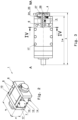
- Fig. 1 shows a perspective schematic diagram of a housing-less electric traction machine 1 according to the invention.
- the electric traction machine 1 which is designed as an internal rotor, consists of a stator 2, which is constructed from a corresponding stator laminated core 3, and a movable part, the rotor 5, which consists of a rotor shaft 4 and one on it attached rotor laminated core 6 is constructed.
- the stator laminated core 3 of the stator 2 is arranged between two external press plates 7 and 8. Outside the press plates 7 and 8 there is a bearing plate 29 and 30, which have corresponding bearings 24 (shown in dashed lines) for supporting the rotor shaft 4.
- the electric traction machine 1 can also contain only one bearing 24 in a bearing shield 29 or 30 and the second bearing for the rotor shaft 4 can also be in a clutch 21 or a gearbox 22 (see Fig. 6 ) be integrated.
- At least two heat sinks 10, each with at least one cooling channel 11 for guiding a cooling liquid K are arranged opposite one another along part of the circumference of the stator laminated core 3 between the press plates 7 and 8 on the surface of the stator laminated core 3, so that the electric traction machine 1 is one has a reduced height h compared to the width b (see Fig. 2 ).
- Tension strips 9 are arranged between the press plates 7, 8.
- the heat sinks 10 can be connected to the pull strips 9.
- a cooling liquid K is guided in the at least one cooling channel 11 in order to be able to dissipate the heat generated in the electric traction machine 1.
- Fig. 2 shows a further perspective schematic diagram of a housing-less electric traction machine 1 according to the invention.
- the result is an electric traction machine 1 which has a height h that is reduced compared to the width b.
- the coolant K can be conveyed into the heat sink 10 and out of the heat sink 10 via corresponding inlets 13 and outlets 14 in the heat sink 10.
- the heat sink 10 can be connected to the pull strips 9 via fastening screws 17.
- the heat sinks can also be fastened to the press plates 7, 8 or to the stator laminated core 3 (not shown) using appropriate fastening screws or fastening elements.
- FIG. 3 is a partially sectioned view of the housing-less electric traction machine 1 according to Fig. 2 shown.
- the rotor 5 of the electric traction machine 1 which consists of the rotor shaft 4 and the rotor laminated core 6, is shown.
- a heat pipe 26 can be arranged in the rotor shaft 4, the free end of which can be connected to a heat sink 27.
- the length l w of the rotor shaft 4 can be between 100 mm and 980 mm.
- the length l of the entire electrical machine for example, between 110 mm and 1000 mm.
- a rotary encoder (not shown) can be arranged on the non-drive side NA of the electric traction machine 1, which can be used to regulate the number of revolutions.
- a toothed disk, which generates the signals for such a rotary encoder, could be used as a heat sink 27 for the heat pipe 26.
- Fig. 4 shows the sectional view through the housing-less electric traction machine 1 according to Fig. 3 along the section line IV - IV. From this sectional view, a heat sink 10 with the inlet 13 and the outlet 14 for guiding the coolant K in at least one cooling channel 11 can be seen.
- the heat sink 10 can be connected to the stator laminated core 3 via a thermally conductive foil or thermal paste 20, whereby the heat occurring in the stator laminated core 3 can be transferred to the coolant K in the heat sink 10 and dissipated accordingly.
- the electric traction machine 1 is given the necessary strength via the pull strips 9 between the press plates 7, 8.
- the heat sink 10 extends over a circumferential angle ⁇ of slightly less than 90°.
- the diameter d of the rotor shaft 4 is, for example, 20 mm to 100 mm.
- Fig. 5 shows the sectional view through the housing-less electric traction machine 1 according to Fig. 4 along the section line V - V.
- the coolant K enters the cooling channel 11 of the heat sink 10 via the inlet 13 and is discharged again via an outlet 14.
- About the holes 18 is done using appropriate fastening screws 17 (see Figs. 2 and 3 ) an attachment of the heat sink 10 to the pull strips 9 (not shown).
- FIG. 6 a perspective schematic diagram of a housing-less electric traction machine 1 connected to a transmission 22 is shown.
- a clutch 21 for connection to a gearbox 22 can be provided on the drive side A of the rotor shaft 4.
- the clutch 21 can be realized, for example, by a curved tooth clutch 23.
Landscapes
- Engineering & Computer Science (AREA)
- Power Engineering (AREA)
- Motor Or Generator Cooling System (AREA)
- Motor Or Generator Frames (AREA)
- Electric Propulsion And Braking For Vehicles (AREA)
Claims (10)
- Machine de traction électrique sans boîtier (1), avec un stator (2) construit à partir d'un noyau feuilleté de stator (3) et un arbre de rotor (4) avec un rotor (5) fixé à celui-ci, construit à partir d'un noyau feuilleté de rotor (6), où le noyau feuilleté de stator (3) est disposé entre deux plaques de pression (7, 8) situées à l'extérieur et au moins un flasque (29, 30) comportant dans chaque cas un roulement (24) pour l'arbre de rotor (4), et entre les plaques de pression (7, 8) sont disposées des barres de traction (9), où au moins deux dissipateurs thermiques (10), chacun avec au moins un canal de refroidissement (11) pour guider un fluide de refroidissement, sont disposés l'un en face de l'autre sur la surface du noyau feuilleté de stator (3), le long d'une partie de la circonférence du noyau feuilleté de stator (3) entre les plaques de pression (7, 8), de sorte que la machine de traction électrique sans boîtier (1) présente une hauteur (h) réduite par rapport à la largeur (b), où chaque dissipateur thermique (10) est relié par le biais de vis de fixation (17) ou d'autres éléments de fixation avec au moins une barre de traction (9) et/ou les plaques de pression (7, 8) et/ou le noyau feuilleté de stator (3), caractérisée en ce que les canaux de refroidissement (11) sont prévus pour guider un liquide de refroidissement, et en ce que les plaques de pression (7, 8) sont agencées de manière sensiblement rectangulaire et le noyau feuilleté de stator (3) est agencé de manière sensiblement carrée.
- Machine de traction électrique sans boîtier (1) selon la revendication 1, caractérisée en ce que le long de la circonférence du noyau feuilleté de stator (3) quatre barres de traction (9) et deux dissipateurs thermiques (10) sont disposés en se faisant face sur un angle de circonférence (α) de 60° à 135° dans chaque cas, de préférence de sensiblement 90°, à chaque fois entre deux barres de traction (9).
- Machine de traction électrique sans boîtier (1) selon la revendication 1 ou 2, caractérisée en ce que le au moins un canal de refroidissement (11) comporte dans chaque dissipateur thermique (10) au moins une entrée (13) et au moins une sortie (14) pour le liquide de refroidissement (K), et en ce que le au moins un canal de refroidissement (11) s'étend de préférence en forme de méandre.
- Machine de traction électrique sans boîtier (1) selon l'une des revendications 1 à 3, caractérisée en ce que chaque dissipateur thermique (10) est relié au noyau feuilleté de stator (3) par assemblage de forme au moins par endroits.
- Machine de traction électrique sans boîtier (1) selon l'une des revendications 1 à 4, caractérisée en ce qu'une feuille conductrice de la chaleur ou une pâte conductrice de la chaleur (20) est disposée entre chaque dissipateur thermique (10) et le noyau feuilleté de stator (3).
- Machine de traction électrique sans boîtier (1) selon l'une des revendications 1 à 3, caractérisée en ce que chaque dissipateur thermique (10) est relié au noyau feuilleté de stator (3) par assemblage de forme au moins par endroits.
- Machine de traction électrique sans boîtier (1) selon l'une des revendications 1 à 6, caractérisée en ce que le liquide de refroidissement (K) est formé par de l'eau de refroidissement.
- Machine de traction électrique sans boîtier (1) selon l'une des revendications 1 à 7, caractérisée en ce que du côté entraînement (A) de l'arbre de rotor (4) est disposé un accouplement (21) pour la liaison à un engrenage (22), de préférence accouplement à denture sphérique (23).
- Machine de traction électrique sans boîtier (1) selon l'une des revendications 1 à 8, caractérisée en ce que le au moins un roulement (24) dans le au moins un flasque (29, 30) est constitué par un roulement à billes à portée oblique (25).
- Machine de traction électrique sans boîtier (1) selon l'une des revendications 1 à 9, caractérisée en ce que dans le noyau feuilleté de rotor (6) est disposé au moins un caloduc (26) à extrémité libre ou en liaison avec un dissipateur thermique (27) pour refroidir le rotor (3).
Applications Claiming Priority (2)
| Application Number | Priority Date | Filing Date | Title |
|---|---|---|---|
| EP20190302.8A EP3955435A1 (fr) | 2020-08-10 | 2020-08-10 | Moteur de traction électrique sans boitier |
| PCT/EP2021/071833 WO2022033943A1 (fr) | 2020-08-10 | 2021-08-05 | Machine de traction électrique non close |
Publications (3)
| Publication Number | Publication Date |
|---|---|
| EP4158764A1 EP4158764A1 (fr) | 2023-04-05 |
| EP4158764C0 EP4158764C0 (fr) | 2024-01-03 |
| EP4158764B1 true EP4158764B1 (fr) | 2024-01-03 |
Family
ID=72039436
Family Applications (2)
| Application Number | Title | Priority Date | Filing Date |
|---|---|---|---|
| EP20190302.8A Withdrawn EP3955435A1 (fr) | 2020-08-10 | 2020-08-10 | Moteur de traction électrique sans boitier |
| EP21755472.4A Active EP4158764B1 (fr) | 2020-08-10 | 2021-08-05 | Moteur de traction électrique sans boitier |
Family Applications Before (1)
| Application Number | Title | Priority Date | Filing Date |
|---|---|---|---|
| EP20190302.8A Withdrawn EP3955435A1 (fr) | 2020-08-10 | 2020-08-10 | Moteur de traction électrique sans boitier |
Country Status (4)
| Country | Link |
|---|---|
| EP (2) | EP3955435A1 (fr) |
| ES (1) | ES2973415T3 (fr) |
| PL (1) | PL4158764T3 (fr) |
| WO (1) | WO2022033943A1 (fr) |
Families Citing this family (1)
| Publication number | Priority date | Publication date | Assignee | Title |
|---|---|---|---|---|
| DE102022003494A1 (de) | 2021-10-13 | 2023-04-13 | Sew-Eurodrive Gmbh & Co Kg | Elektromotor mit Statorgehäuse |
Family Cites Families (5)
| Publication number | Priority date | Publication date | Assignee | Title |
|---|---|---|---|---|
| US3801843A (en) * | 1972-06-16 | 1974-04-02 | Gen Electric | Rotating electrical machine having rotor and stator cooled by means of heat pipes |
| AT403267B (de) | 1991-12-19 | 1997-12-29 | Bombardier Wien Schienen | Schienenfahrzeug, insbesondere niederflurfahrzeug |
| CN100547883C (zh) | 2006-10-17 | 2009-10-07 | 中国南车集团株洲电力机车研究所 | 一种用于牵引电机的水冷却方法及结构 |
| EP2806535A1 (fr) * | 2013-05-24 | 2014-11-26 | Siemens Aktiengesellschaft | Machine électrique refroidie par air avec nervures de refroidissement en tôle de stator |
| JP2017085765A (ja) * | 2015-10-28 | 2017-05-18 | 富士電機株式会社 | 回転電機 |
-
2020
- 2020-08-10 EP EP20190302.8A patent/EP3955435A1/fr not_active Withdrawn
-
2021
- 2021-08-05 WO PCT/EP2021/071833 patent/WO2022033943A1/fr not_active Ceased
- 2021-08-05 ES ES21755472T patent/ES2973415T3/es active Active
- 2021-08-05 EP EP21755472.4A patent/EP4158764B1/fr active Active
- 2021-08-05 PL PL21755472.4T patent/PL4158764T3/pl unknown
Also Published As
| Publication number | Publication date |
|---|---|
| PL4158764T3 (pl) | 2024-05-06 |
| EP4158764A1 (fr) | 2023-04-05 |
| ES2973415T3 (es) | 2024-06-20 |
| WO2022033943A1 (fr) | 2022-02-17 |
| EP4158764C0 (fr) | 2024-01-03 |
| EP3955435A1 (fr) | 2022-02-16 |
Similar Documents
| Publication | Publication Date | Title |
|---|---|---|
| EP3878080B1 (fr) | Machine électrique munie d'un dispositif de refroidissement par fluide | |
| EP3507889B1 (fr) | Rotor pour une machine electrique | |
| EP3766164B1 (fr) | Véhicule électrique | |
| EP3511223A1 (fr) | Bogie d'un véhicule ferroviaire | |
| EP4320709A1 (fr) | Stator de machine électrique à flux axial et machine à flux axial | |
| DE102013208976B4 (de) | Elektrische Antriebsvorrichtung und Kraftfahrzeug mit dieser | |
| WO2002043229A2 (fr) | Ralentisseur, s'utilisant notamment comme dispositif de freinage ou de freinage auxiliaire pour vehicules sou similaires, en particulier vehicules sur rails | |
| EP0906842B1 (fr) | Dispositif d'entraínement des roues | |
| WO2019110275A1 (fr) | Machine électrique, en particulier pour véhicule | |
| EP2806535A1 (fr) | Machine électrique refroidie par air avec nervures de refroidissement en tôle de stator | |
| EP4158764A1 (fr) | Machine de traction électrique non close | |
| DE102022107665A1 (de) | Statoreinheit, Antriebseinheit und Antriebsanordnung | |
| DE19860618C1 (de) | Elektrische Antriebsmaschinenbaueinheit | |
| EP3857684B1 (fr) | Machine de traction électrique sans boîtier | |
| DE10129152A1 (de) | Antriebsbaugruppe und Antriebsvorrichtung für Fahrzeuge | |
| DE102019218582A1 (de) | Elektromaschine mit Kühlvorrichtung | |
| EP3944468B1 (fr) | Agencement d'enroulement pour un moteur linéaire pourvu de paires parallèles de bobines à partir d'un conducteur électrique connexe | |
| AT504056B1 (de) | Gekapselte, elektrische maschine | |
| DE102018218813A1 (de) | Elektrische Maschine mit einer Fluid-Kühleinrichtung | |
| DE102019214664A1 (de) | Antriebsvorrichtung und Kraftfahrzeug | |
| EP3456571A1 (fr) | Véhicule d'exploitation minière pourvu d'entraînement de moyeu de roue | |
| DE102023205211A1 (de) | Elektrische Maschine mit einer Förderstruktur sowie Fahrzeug mit der elektrischen Maschine | |
| DE102024003796A1 (de) | Axialflussmaschine für ein Kraftfahrzeug sowie Kraftfahrzeug | |
| DE102024209545A1 (de) | Traktionsmotor mit Direktkühlung | |
| DE102024129542A1 (de) | Stirnseitige Scheibe mit einem Ringkanal für einen Rotor einer elektrischen Maschine, insbesondere eines extern erregten Synchronmotors |
Legal Events
| Date | Code | Title | Description |
|---|---|---|---|
| STAA | Information on the status of an ep patent application or granted ep patent |
Free format text: STATUS: UNKNOWN |
|
| STAA | Information on the status of an ep patent application or granted ep patent |
Free format text: STATUS: THE INTERNATIONAL PUBLICATION HAS BEEN MADE |
|
| PUAI | Public reference made under article 153(3) epc to a published international application that has entered the european phase |
Free format text: ORIGINAL CODE: 0009012 |
|
| STAA | Information on the status of an ep patent application or granted ep patent |
Free format text: STATUS: REQUEST FOR EXAMINATION WAS MADE |
|
| 17P | Request for examination filed |
Effective date: 20221229 |
|
| AK | Designated contracting states |
Kind code of ref document: A1 Designated state(s): AL AT BE BG CH CY CZ DE DK EE ES FI FR GB GR HR HU IE IS IT LI LT LU LV MC MK MT NL NO PL PT RO RS SE SI SK SM TR |
|
| GRAP | Despatch of communication of intention to grant a patent |
Free format text: ORIGINAL CODE: EPIDOSNIGR1 |
|
| STAA | Information on the status of an ep patent application or granted ep patent |
Free format text: STATUS: GRANT OF PATENT IS INTENDED |
|
| DAV | Request for validation of the european patent (deleted) | ||
| DAX | Request for extension of the european patent (deleted) | ||
| INTG | Intention to grant announced |
Effective date: 20230824 |
|
| GRAS | Grant fee paid |
Free format text: ORIGINAL CODE: EPIDOSNIGR3 |
|
| GRAA | (expected) grant |
Free format text: ORIGINAL CODE: 0009210 |
|
| STAA | Information on the status of an ep patent application or granted ep patent |
Free format text: STATUS: THE PATENT HAS BEEN GRANTED |
|
| AK | Designated contracting states |
Kind code of ref document: B1 Designated state(s): AL AT BE BG CH CY CZ DE DK EE ES FI FR GB GR HR HU IE IS IT LI LT LU LV MC MK MT NL NO PL PT RO RS SE SI SK SM TR |
|
| REG | Reference to a national code |
Ref country code: GB Ref legal event code: FG4D Free format text: NOT ENGLISH |
|
| REG | Reference to a national code |
Ref country code: CH Ref legal event code: EP |
|
| REG | Reference to a national code |
Ref country code: DE Ref legal event code: R096 Ref document number: 502021002381 Country of ref document: DE |
|
| REG | Reference to a national code |
Ref country code: IE Ref legal event code: FG4D Free format text: LANGUAGE OF EP DOCUMENT: GERMAN |
|
| U01 | Request for unitary effect filed |
Effective date: 20240129 |
|
| U07 | Unitary effect registered |
Designated state(s): AT BE BG DE DK EE FI FR IT LT LU LV MT NL PT SE SI Effective date: 20240206 |
|
| PG25 | Lapsed in a contracting state [announced via postgrant information from national office to epo] |
Ref country code: IS Free format text: LAPSE BECAUSE OF FAILURE TO SUBMIT A TRANSLATION OF THE DESCRIPTION OR TO PAY THE FEE WITHIN THE PRESCRIBED TIME-LIMIT Effective date: 20240503 |
|
| PG25 | Lapsed in a contracting state [announced via postgrant information from national office to epo] |
Ref country code: GR Free format text: LAPSE BECAUSE OF FAILURE TO SUBMIT A TRANSLATION OF THE DESCRIPTION OR TO PAY THE FEE WITHIN THE PRESCRIBED TIME-LIMIT Effective date: 20240404 |
|
| PG25 | Lapsed in a contracting state [announced via postgrant information from national office to epo] |
Ref country code: RS Free format text: LAPSE BECAUSE OF FAILURE TO SUBMIT A TRANSLATION OF THE DESCRIPTION OR TO PAY THE FEE WITHIN THE PRESCRIBED TIME-LIMIT Effective date: 20240403 Ref country code: HR Free format text: LAPSE BECAUSE OF FAILURE TO SUBMIT A TRANSLATION OF THE DESCRIPTION OR TO PAY THE FEE WITHIN THE PRESCRIBED TIME-LIMIT Effective date: 20240103 |
|
| PG25 | Lapsed in a contracting state [announced via postgrant information from national office to epo] |
Ref country code: CZ Free format text: LAPSE BECAUSE OF FAILURE TO SUBMIT A TRANSLATION OF THE DESCRIPTION OR TO PAY THE FEE WITHIN THE PRESCRIBED TIME-LIMIT Effective date: 20240103 |
|
| PG25 | Lapsed in a contracting state [announced via postgrant information from national office to epo] |
Ref country code: RS Free format text: LAPSE BECAUSE OF FAILURE TO SUBMIT A TRANSLATION OF THE DESCRIPTION OR TO PAY THE FEE WITHIN THE PRESCRIBED TIME-LIMIT Effective date: 20240403 Ref country code: NO Free format text: LAPSE BECAUSE OF FAILURE TO SUBMIT A TRANSLATION OF THE DESCRIPTION OR TO PAY THE FEE WITHIN THE PRESCRIBED TIME-LIMIT Effective date: 20240403 Ref country code: IS Free format text: LAPSE BECAUSE OF FAILURE TO SUBMIT A TRANSLATION OF THE DESCRIPTION OR TO PAY THE FEE WITHIN THE PRESCRIBED TIME-LIMIT Effective date: 20240503 Ref country code: HR Free format text: LAPSE BECAUSE OF FAILURE TO SUBMIT A TRANSLATION OF THE DESCRIPTION OR TO PAY THE FEE WITHIN THE PRESCRIBED TIME-LIMIT Effective date: 20240103 Ref country code: GR Free format text: LAPSE BECAUSE OF FAILURE TO SUBMIT A TRANSLATION OF THE DESCRIPTION OR TO PAY THE FEE WITHIN THE PRESCRIBED TIME-LIMIT Effective date: 20240404 Ref country code: CZ Free format text: LAPSE BECAUSE OF FAILURE TO SUBMIT A TRANSLATION OF THE DESCRIPTION OR TO PAY THE FEE WITHIN THE PRESCRIBED TIME-LIMIT Effective date: 20240103 |
|
| U20 | Renewal fee for the european patent with unitary effect paid |
Year of fee payment: 4 Effective date: 20240808 |
|
| REG | Reference to a national code |
Ref country code: DE Ref legal event code: R097 Ref document number: 502021002381 Country of ref document: DE |
|
| PG25 | Lapsed in a contracting state [announced via postgrant information from national office to epo] |
Ref country code: SM Free format text: LAPSE BECAUSE OF FAILURE TO SUBMIT A TRANSLATION OF THE DESCRIPTION OR TO PAY THE FEE WITHIN THE PRESCRIBED TIME-LIMIT Effective date: 20240103 |
|
| PG25 | Lapsed in a contracting state [announced via postgrant information from national office to epo] |
Ref country code: SK Free format text: LAPSE BECAUSE OF FAILURE TO SUBMIT A TRANSLATION OF THE DESCRIPTION OR TO PAY THE FEE WITHIN THE PRESCRIBED TIME-LIMIT Effective date: 20240103 |
|
| PG25 | Lapsed in a contracting state [announced via postgrant information from national office to epo] |
Ref country code: SM Free format text: LAPSE BECAUSE OF FAILURE TO SUBMIT A TRANSLATION OF THE DESCRIPTION OR TO PAY THE FEE WITHIN THE PRESCRIBED TIME-LIMIT Effective date: 20240103 Ref country code: SK Free format text: LAPSE BECAUSE OF FAILURE TO SUBMIT A TRANSLATION OF THE DESCRIPTION OR TO PAY THE FEE WITHIN THE PRESCRIBED TIME-LIMIT Effective date: 20240103 Ref country code: RO Free format text: LAPSE BECAUSE OF FAILURE TO SUBMIT A TRANSLATION OF THE DESCRIPTION OR TO PAY THE FEE WITHIN THE PRESCRIBED TIME-LIMIT Effective date: 20240103 |
|
| PLBE | No opposition filed within time limit |
Free format text: ORIGINAL CODE: 0009261 |
|
| STAA | Information on the status of an ep patent application or granted ep patent |
Free format text: STATUS: NO OPPOSITION FILED WITHIN TIME LIMIT |
|
| 26N | No opposition filed |
Effective date: 20241007 |
|
| PG25 | Lapsed in a contracting state [announced via postgrant information from national office to epo] |
Ref country code: MC Free format text: LAPSE BECAUSE OF FAILURE TO SUBMIT A TRANSLATION OF THE DESCRIPTION OR TO PAY THE FEE WITHIN THE PRESCRIBED TIME-LIMIT Effective date: 20240103 |
|
| PG25 | Lapsed in a contracting state [announced via postgrant information from national office to epo] |
Ref country code: IE Free format text: LAPSE BECAUSE OF NON-PAYMENT OF DUE FEES Effective date: 20240805 |
|
| U20 | Renewal fee for the european patent with unitary effect paid |
Year of fee payment: 5 Effective date: 20250808 |
|
| PGFP | Annual fee paid to national office [announced via postgrant information from national office to epo] |
Ref country code: ES Payment date: 20250917 Year of fee payment: 5 |
|
| PGFP | Annual fee paid to national office [announced via postgrant information from national office to epo] |
Ref country code: PL Payment date: 20250716 Year of fee payment: 5 |
|
| PGFP | Annual fee paid to national office [announced via postgrant information from national office to epo] |
Ref country code: GB Payment date: 20250822 Year of fee payment: 5 |
|
| PGFP | Annual fee paid to national office [announced via postgrant information from national office to epo] |
Ref country code: CH Payment date: 20250901 Year of fee payment: 5 |
|
| PG25 | Lapsed in a contracting state [announced via postgrant information from national office to epo] |
Ref country code: CY Free format text: LAPSE BECAUSE OF FAILURE TO SUBMIT A TRANSLATION OF THE DESCRIPTION OR TO PAY THE FEE WITHIN THE PRESCRIBED TIME-LIMIT; INVALID AB INITIO Effective date: 20210805 |
|
| PG25 | Lapsed in a contracting state [announced via postgrant information from national office to epo] |
Ref country code: HU Free format text: LAPSE BECAUSE OF FAILURE TO SUBMIT A TRANSLATION OF THE DESCRIPTION OR TO PAY THE FEE WITHIN THE PRESCRIBED TIME-LIMIT; INVALID AB INITIO Effective date: 20210805 |