EP4159065A1 - Zerstäuber mit verbesserter luftdurchlassstruktur und elektronische zigarette damit - Google Patents
Zerstäuber mit verbesserter luftdurchlassstruktur und elektronische zigarette damit Download PDFInfo
- Publication number
- EP4159065A1 EP4159065A1 EP22196300.2A EP22196300A EP4159065A1 EP 4159065 A1 EP4159065 A1 EP 4159065A1 EP 22196300 A EP22196300 A EP 22196300A EP 4159065 A1 EP4159065 A1 EP 4159065A1
- Authority
- EP
- European Patent Office
- Prior art keywords
- air
- air inlet
- electronic cigarette
- air outlet
- area
- Prior art date
- Legal status (The legal status is an assumption and is not a legal conclusion. Google has not performed a legal analysis and makes no representation as to the accuracy of the status listed.)
- Pending
Links
Images


Classifications
-
- A—HUMAN NECESSITIES
- A24—TOBACCO; CIGARS; CIGARETTES; SIMULATED SMOKING DEVICES; SMOKERS' REQUISITES
- A24F—SMOKERS' REQUISITES; MATCH BOXES; SIMULATED SMOKING DEVICES
- A24F40/00—Electrically operated smoking devices; Component parts thereof; Manufacture thereof; Maintenance or testing thereof; Charging means specially adapted therefor
- A24F40/40—Constructional details, e.g. connection of cartridges and battery parts
- A24F40/48—Fluid transfer means, e.g. pumps
- A24F40/485—Valves; Apertures
-
- A—HUMAN NECESSITIES
- A24—TOBACCO; CIGARS; CIGARETTES; SIMULATED SMOKING DEVICES; SMOKERS' REQUISITES
- A24F—SMOKERS' REQUISITES; MATCH BOXES; SIMULATED SMOKING DEVICES
- A24F40/00—Electrically operated smoking devices; Component parts thereof; Manufacture thereof; Maintenance or testing thereof; Charging means specially adapted therefor
- A24F40/10—Devices using liquid inhalable precursors
Definitions
- the present disclosure relates to the field of electronic cigarettes, and particularly, to an atomizer with an upgraded air passage structure and an electronic cigarette having the same.
- An atomizer of the electronic cigarette generally heats the tobacco liquid to generate an aerosol then sucked by users, in a process that the tobacco liquid is aerosolized some hazardous material such as tars won't be produced, which may greatly reduce a rate of endangering to users' bodies.
- the atomizer in the prior art utilizes a type of a straight-through air passage, that is, an air inlet is disposed below or over an atomizing chamber where the heating piece is disposed therein.
- a type of a straight-through air passage that is, an air inlet is disposed below or over an atomizing chamber where the heating piece is disposed therein.
- exterior air is sucked via the lower air inlet, flowing upward and passing through the atomizing chamber, then straight-through flowing upward, and sucked via a top air outlet, of which the air inlet is closer to the above heating piece.
- the present disclosure generally relates to an atomizer with an upgraded air passage structure and an electronic cigarette having the same, reducing a rate of the condensing tobacco liquid leaking out from the air passage.
- the present disclosure relates to the atomizer with the air passage structure including a housing, a heating piece and an air passage disposed in the housing; the heating piece is disposed inside an atomizer chamber, a blocking piece is disposed in the air passage and configured for blocking an airflow.
- the blocking piece divides the air passage into an air inlet area and an air outlet area; the air outlet area and the air inlet area are both disposed at a different axial position with the atomizing chamber.
- the atomizing chamber is respectively communicated with the air inlet area and the air outlet area. The airflow in the air inlet area flows downwards to the atomizing chamber, then flows upwards to the air outlet area.
- a first air inlet is disposed on the housing and at an axial position above the blocking piece.
- the first air inlet is disposed on a side wall of the housing, communicated with the air inlet area via an air pipe inside the side wall of the housing.
- the air inlet area has a second air inlet communicated with the atomizing chamber, the second air inlet and the first air inlet are staggered in a certain angle.
- the air outlet area has a first air inlet communicated with the atomizing chamber; the first air outlet and the second air inlet are disposed at two sides of the atomizing chamber.
- a top of the housing has a second air outlet, the second air outlet and the first air outlet are staggered in a certain angle.
- a stagger angle between the second air outlet and the first air outlet is 90 degree; and a stagger angle between the second air inlet and the first air inlet is 90 degree.
- the blocking piece at comprises a silicon seat and a base; the air inlet area and the air outlet area are defined by the silicon seat matching with the base and a supporter for fixing the heating piece; where the atomizing chamber is defined by the base and the supporter for fixing the heating piece; a bottom of the base has a recessed shape, used for accumulating a certain amount of the tobacco liquid.
- a protuberant separating bar is formed on a surface of the blocking piece; the separating bar is integrally manufactured with the silicon seat; the separating bar defines the air inlet area and the air outlet area by dividing a space between the housing and the liquid storage cup into two side areas.
- the opening at the bottom end of the liquid storage cup is filled up with a tobacco conducting layer, the heating piece contacts the tobacco conducting layer.
- an electronic cigarette has the aforementioned atomizer with an upgraded air passage structure, and a power supply for supplying power to the atomizer.
- an electronic cigarette atomizer with an air passage structure may include a housing, a heating piece, and an air passage may be disposed in the housing.
- the heating piece may be disposed inside an atomizer chamber.
- a blocking piece may be disposed in the air passage and the blocking piece may be configured for blocking an airflow; the blocking piece may divide the air passage into an air inlet area and an air outlet area.
- the atomization chamber may be connected to the air inlet area and connected to the air outlet area; in other words, the atomizing chamber may be respectively communicated with the air inlet area and the air outlet area.
- the atomizer may be configured to allow air to flow through the air inlet area, the atomizing chamber, and then the air outlet area.
- the blocking piece may include a silicone seat and a base; the air inlet area and the air outlet area may be separated by the silicone seat, the base and a supported for fixing the heating piece.
- the atomizer of the electronic cigarette refers to the upgraded air passage, a part of the air passage is divided into independent air inlet area and air outlet area via the blocking piece.
- the air inlet area and the air outlet area are disposed at an axial position above the atomizing chamber, allowing the air inlet passage and the air outlet passage being disposed at one same axial position that is above the atomizing chamber, which replaces the existing design of inletting air from an axial position below the atomizing chamber, to reduce the rate of leakage of the tobacco liquid in the atomizing chamber.
- the independent air inlet area and the air outlet area are disposed at one same axial position that is different with the atomizing chamber, not the straight-through type, with the staggered air inlets/outlets to prolong the whole air passage further to avoid the condensing tobacco liquid in the atomizing chamber leaking out, therefore the condensing tobacco liquid may be heated and aerosolized for multiple times.
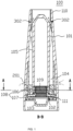
- the present disclosure relates to an atomizer of an electronic cigarette 100 with an upgraded air passage, including a housing 101, a heating piece 102 and an air passage 104 disposed inside the housing 101; the heating piece 102 is disposed inside the atomizing chamber 103 and configured for heating the tobacco liquid to generate an aerosol in the atomizing chamber 103.
- a top of the housing 101 has a mouth piece 110 for a user to suck the aerosol, the mouth piece 110 is in communication with the atomizing chamber 103.
- a blocking piece 108 is disposed below the air passage 104 and configured for blocking an airflow.
- the blocking piece 108 divides the air passage into an air inlet area 111 and an air outlet area 112 (with reference to FIG. 2 ).
- the air inlet area 111 and the air outlet area 112 are correspondingly communicated with the air inlet and the air outlet, as concretely described hereinafter.
- the air outlet area 112 and the air inlet area 111 are respectively disposed at a different axial position with the atomizing chamber 103.
- the atomizing chamber 103 is respectively communicated with the air inlet area 111 and the air outlet area 112.
- the airflow in the air inlet area 111 flows downwards to the atomizing chamber 103, then flows upwards to the air outlet area 112, which avoids the tobacco liquid condensing in the atomizing chamber 103 easily leaking out from the air inlets and the air outlets, whereas, the condensing tobacco liquid is accumulated in the atomizing chamber 103 in favor of reheating, re-aerosolizing and recycling for multiple times.
- the above blocking piece 108 at least includes a silicon seat 106 and a base 107.
- the above air inlet area 111 and the air outlet area 112 are formed by a specialized shape and structure of the silicon seat 106 matching with the base 107, and a supporter for fixing the heating piece 102.
- the above atomizing chamber 103 is formed by the base 107 and the supporter for fixing the heating piece 102.
- a bottom of the base 107 has a recessed shape, used for accumulating a certain amount of the tobacco liquid.
- a protuberant separating bar 1061 is formed on a surface of the blocking piece 108.
- the separating bar 1061 is integrally manufactured with the above silicon seat 106.
- the separating bar 1061 divides a circular space between the housing 101 and the liquid storage cup 105 into two side areas of left and right, that is, the air inlet area 111 and the air outlet area 112.
- a first air inlet 201 is formed on the housing 101, at an axial position above the blocking piece 108.
- the first air inlet 201 is located at the axial position above the blocking piece 108 and the atomizing chamber 103, avoiding the tobacco liquid leaking from a lower end of atomizer 100 when the atomizer 100 is placed at a normal state.
- the first air inlet 201 is disposed on a side wall of the housing 101, as shown in FIG. 1 , the number of the first air inlets 201 is two, both are dispersed on two side walls of the housing 101 and communicated with the air inlet area 111 via an air pipe extending downward, inside the side wall of the housing 101.
- the air inlet area 111 has a second air inlet 202 communicated with the atomizing chamber 103 at a lower axial position.
- the second air inlet 202 and the first air inlet 201 are staggered to a certain angle along a horizontal direction, in a preferred embodiment, the angle is 90 degree.
- the setting of the second air inlet 202 and the first air inlet 201 being staggered may prolong the whole air inlet passage to reduce a rate of the tobacco liquid leaking out from the atomizing chamber.
- the air outlet area 112 has a first air outlet 301 communicated with the atomizing chamber 103.
- the first air outlet 301 and the second air inlet 202 are disposed at two sides of the atomizing chamber 103.
- the first air outlet 301 and the second air inlet 202 are symmetrically disposed at two sides of the mid-positioned heating piece 102.
- a top of the housing 101 has a second air outlet 302, the second air outlet 302 is communicated with an air outlet passage extending upwards and a mouth piece 110 at an upper axial position.
- the second air outlet 302 and the first air outlet 301 are staggered in a certain angle.
- a stagger angle between the second air outlet 302 and the first air outlet 301 is 90 degree, enabling the second air outlet 302 and the above first air inlet 201 disposed at a same axial section B-B, and the air inlet passage and the air outlet passage are separated by the separating bar 1061 of the blocking piece 108.
- the second air outlet 302 and the first air outlet 301 being staggered to set may prolong the air passage and reduce a rate of the tobacco liquid leaking out of the atomizing chamber.
- the exterior air flows into the atomizer 100 via the first air inlet 201 that is disposed on the side wall of the housing 101, then flows downwards. After blocked by the blocking piece 108 the air flows transversely into the air inlet area 111. After blocked by the separating bar 1061, the air in the air inlet area 111 spins 90 degree then flows into the second air inlet 202, flowing downwards to the atomizing chamber 103 from the second air inlet 202.
- the air carrying the aerosol generated by the tobacco liquid in the atomizing chamber 103 flows from the other side of the atomizing chamber 103 upwards to air outlet area 112 via the first air outlet 301. Since a passage right there above the first air outlet 301 is closed, the air is blocked by the closed passage continues spinning 90 degree to flow upwards to the second air outlet 302, ultimately sucked out from the mouth piece 110.
- the liquid storage cup 105 is set at a center of the housing 101, a bottom end of the liquid storage cup 105 has an opening; the side wall of the liquid storage cup is integrally manufactured with the housing 101, the liquid storage cup 105 has a chamber for storing the tobacco liquid.
- the air passage is defined by areas surrounding and below the liquid storage cup 105. The above air inlet area 111, the air outlet area 112 and the atomizing chamber 103 forms as a part of the air passage.
- the opening at the bottom end of the liquid storage cup 105 is filled up with a tobacco conducting layer 109, the heating piece 102 contacts a surface of the tobacco conducting layer 109.
- the tobacco conducting layer 109 is made of any one of fiber cottons, non-woven fabrics and micro-porous materials such as polymer foam materials or micro-porous ceramics, used for providing tobacco liquid to the heating piece 102 at a certain oozing speed.
- the heating piece 102 is a heating piece or net.
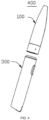
- an electronic cigarette 400 is further disclosed in accordance with the present disclosure, which includes the aforementioned atomizer 100 with the upgraded air passage structure and a power supply 300 for supplying power to the atomizer 100.
- the atomizer 100 and the power supply 300 may be detachably connected by a screw threaded, a snap joint or a magnetic attraction etc.
Landscapes
- Electrostatic Spraying Apparatus (AREA)
- Nozzles (AREA)
Applications Claiming Priority (2)
| Application Number | Priority Date | Filing Date | Title |
|---|---|---|---|
| CN201720710217.0U CN207040883U (zh) | 2017-06-19 | 2017-06-19 | 具有改进气道构造的电子烟雾化器 |
| EP18177952.1A EP3375306B1 (de) | 2017-06-19 | 2018-06-15 | Zerstäuber mit verbesserter luftdurchlassstruktur und elektronische zigarette damit |
Related Parent Applications (1)
| Application Number | Title | Priority Date | Filing Date |
|---|---|---|---|
| EP18177952.1A Division EP3375306B1 (de) | 2017-06-19 | 2018-06-15 | Zerstäuber mit verbesserter luftdurchlassstruktur und elektronische zigarette damit |
Publications (1)
| Publication Number | Publication Date |
|---|---|
| EP4159065A1 true EP4159065A1 (de) | 2023-04-05 |
Family
ID=61492910
Family Applications (2)
| Application Number | Title | Priority Date | Filing Date |
|---|---|---|---|
| EP22196300.2A Pending EP4159065A1 (de) | 2017-06-19 | 2018-06-15 | Zerstäuber mit verbesserter luftdurchlassstruktur und elektronische zigarette damit |
| EP18177952.1A Active EP3375306B1 (de) | 2017-06-19 | 2018-06-15 | Zerstäuber mit verbesserter luftdurchlassstruktur und elektronische zigarette damit |
Family Applications After (1)
| Application Number | Title | Priority Date | Filing Date |
|---|---|---|---|
| EP18177952.1A Active EP3375306B1 (de) | 2017-06-19 | 2018-06-15 | Zerstäuber mit verbesserter luftdurchlassstruktur und elektronische zigarette damit |
Country Status (3)
| Country | Link |
|---|---|
| US (1) | US11051553B2 (de) |
| EP (2) | EP4159065A1 (de) |
| CN (1) | CN207040883U (de) |
Families Citing this family (10)
| Publication number | Priority date | Publication date | Assignee | Title |
|---|---|---|---|---|
| CN108497561B (zh) * | 2018-06-20 | 2024-02-23 | 铂德(深圳)科技有限公司 | 多分路气流防渗漏电子烟 |
| WO2020034772A1 (zh) * | 2018-08-17 | 2020-02-20 | 深圳雾芯科技有限公司 | 雾化装置及其方法 |
| CN209436269U (zh) * | 2018-12-26 | 2019-09-27 | 常州市派腾电子技术服务有限公司 | 烟弹及电子烟 |
| CN109846096A (zh) * | 2019-04-03 | 2019-06-07 | 刘锐 | 烟弹 |
| KR102353864B1 (ko) * | 2019-04-23 | 2022-01-20 | 주식회사 케이티앤지 | 카트리지 및 이를 포함하는 에어로졸 생성 장치 |
| CN112438434A (zh) * | 2019-08-27 | 2021-03-05 | 深圳市美深威科技有限公司 | 封装式组合电子烟 |
| CN211672453U (zh) * | 2020-01-17 | 2020-10-16 | 常州市派腾电子技术服务有限公司 | 雾化器及其气溶胶发生装置 |
| CN112273728B (zh) * | 2020-10-22 | 2025-05-23 | 深圳麦克韦尔科技有限公司 | 一种电源组件以及电子雾化装置 |
| CN216147233U (zh) * | 2021-07-29 | 2022-04-01 | 深圳麦克韦尔科技有限公司 | 雾化器和电子雾化装置 |
| CN115517409B (zh) * | 2022-09-28 | 2026-02-13 | 爱奇迹(深圳)创新科技有限公司 | 气溶胶产生装置 |
Citations (3)
| Publication number | Priority date | Publication date | Assignee | Title |
|---|---|---|---|---|
| CN203105624U (zh) * | 2013-01-28 | 2013-08-07 | 卓尔悦(常州)电子科技有限公司 | 电子烟雾化器 |
| US20150342255A1 (en) * | 2014-05-30 | 2015-12-03 | Shenzhen Jieshibo Technology Co., Ltd. | Electronic atomization device with adjustable air inlet |
| WO2016029567A1 (zh) * | 2014-08-27 | 2016-03-03 | 深圳葆威道科技有限公司 | 一种回流气流雾化器及包括该雾化器的电子烟 |
Family Cites Families (3)
| Publication number | Priority date | Publication date | Assignee | Title |
|---|---|---|---|---|
| CA2914640A1 (en) * | 2013-06-07 | 2014-12-11 | Kimree Hi-Tech Inc. | Electronic cigarette |
| CN103462224B (zh) * | 2013-08-31 | 2015-10-14 | 卓尔悦(常州)电子科技有限公司 | 电子烟雾化器 |
| CN204907913U (zh) * | 2015-06-19 | 2015-12-30 | 卓尔悦(常州)电子科技有限公司 | 雾化器及其气溶胶发生装置 |
-
2017
- 2017-06-19 CN CN201720710217.0U patent/CN207040883U/zh active Active
-
2018
- 2018-06-15 EP EP22196300.2A patent/EP4159065A1/de active Pending
- 2018-06-15 EP EP18177952.1A patent/EP3375306B1/de active Active
- 2018-06-19 US US16/012,757 patent/US11051553B2/en active Active
Patent Citations (3)
| Publication number | Priority date | Publication date | Assignee | Title |
|---|---|---|---|---|
| CN203105624U (zh) * | 2013-01-28 | 2013-08-07 | 卓尔悦(常州)电子科技有限公司 | 电子烟雾化器 |
| US20150342255A1 (en) * | 2014-05-30 | 2015-12-03 | Shenzhen Jieshibo Technology Co., Ltd. | Electronic atomization device with adjustable air inlet |
| WO2016029567A1 (zh) * | 2014-08-27 | 2016-03-03 | 深圳葆威道科技有限公司 | 一种回流气流雾化器及包括该雾化器的电子烟 |
Also Published As
| Publication number | Publication date |
|---|---|
| US20180360121A1 (en) | 2018-12-20 |
| EP3375306A2 (de) | 2018-09-19 |
| US11051553B2 (en) | 2021-07-06 |
| EP3375306A3 (de) | 2018-12-26 |
| CN207040883U (zh) | 2018-02-27 |
| EP3375306B1 (de) | 2022-10-19 |
Similar Documents
| Publication | Publication Date | Title |
|---|---|---|
| EP4159065A1 (de) | Zerstäuber mit verbesserter luftdurchlassstruktur und elektronische zigarette damit | |
| KR102456689B1 (ko) | 전자담배제품 및 전자담배제품용 카트리지 | |
| JP6849787B2 (ja) | 超音波電子タバコ用の霧化コア並びに霧化器 | |
| JP6714776B2 (ja) | 霧化器及びそれを用いた電子タバコ | |
| CN110574969B (zh) | 雾化装置 | |
| JP2021097712A (ja) | 蒸気供給システムのための液体保管タンク | |
| JP6282262B2 (ja) | アトマイザシステム | |
| EP2649892A1 (de) | Saugdüse für eine elektronische zigarette | |
| CN112690501A (zh) | 雾化腔设于雾化芯支架内的雾化器 | |
| KR20180028953A (ko) | 전자 담배의 분무기 | |
| CN111165878A (zh) | 一种雾化装置 | |
| EP3334300A1 (de) | Stromversorgungsabschnittkonfiguration für eine elektronische vaping-vorrichtung und elektronische vaping-vorrichtung | |
| CN110680022A (zh) | 一种雾化装置 | |
| WO2015161557A1 (zh) | 一种电子烟 | |
| US20220378104A1 (en) | Atomizer and electronic cigarette comrpising the same | |
| CN109043676A (zh) | 防冷凝液吸出的电子烟雾化器及其电子烟 | |
| US20200405982A1 (en) | Aerosolization Conduit For Electronic Drug-Delivery Systems | |
| CN110574970A (zh) | 雾化装置及用于储存溶液的装置 | |
| CN218527698U (zh) | 具有软质雾化芯的电子烟雾化器 | |
| CN118224674A (zh) | 加湿器 | |
| CN115143564B (zh) | 加湿器 | |
| CN113631200A (zh) | 一种香薰机 | |
| CN212088061U (zh) | 雾化装置及用于储存溶液的装置 | |
| CN207040891U (zh) | 具有环绕式气流通道的雾化器和电子烟 | |
| WO2023125859A1 (zh) | 雾化器和电子雾化装置 |
Legal Events
| Date | Code | Title | Description |
|---|---|---|---|
| PUAI | Public reference made under article 153(3) epc to a published international application that has entered the european phase |
Free format text: ORIGINAL CODE: 0009012 |
|
| STAA | Information on the status of an ep patent application or granted ep patent |
Free format text: STATUS: REQUEST FOR EXAMINATION WAS MADE |
|
| STAA | Information on the status of an ep patent application or granted ep patent |
Free format text: STATUS: EXAMINATION IS IN PROGRESS |
|
| 17P | Request for examination filed |
Effective date: 20220922 |
|
| AC | Divisional application: reference to earlier application |
Ref document number: 3375306 Country of ref document: EP Kind code of ref document: P |
|
| AK | Designated contracting states |
Kind code of ref document: A1 Designated state(s): AL AT BE BG CH CY CZ DE DK EE ES FI FR GB GR HR HU IE IS IT LI LT LU LV MC MK MT NL NO PL PT RO RS SE SI SK SM TR |
|
| 17Q | First examination report despatched |
Effective date: 20230317 |