EP4159089B1 - Chaise - Google Patents
Chaise Download PDFInfo
- Publication number
- EP4159089B1 EP4159089B1 EP22197052.8A EP22197052A EP4159089B1 EP 4159089 B1 EP4159089 B1 EP 4159089B1 EP 22197052 A EP22197052 A EP 22197052A EP 4159089 B1 EP4159089 B1 EP 4159089B1
- Authority
- EP
- European Patent Office
- Prior art keywords
- base unit
- swinging
- seat
- upper base
- elastic member
- Prior art date
- Legal status (The legal status is an assumption and is not a legal conclusion. Google has not performed a legal analysis and makes no representation as to the accuracy of the status listed.)
- Active
Links
Images


Classifications
-
- A—HUMAN NECESSITIES
- A47—FURNITURE; DOMESTIC ARTICLES OR APPLIANCES; COFFEE MILLS; SPICE MILLS; SUCTION CLEANERS IN GENERAL
- A47C—CHAIRS; SOFAS; BEDS
- A47C3/00—Chairs characterised by structural features; Chairs or stools with rotatable or vertically-adjustable seats
- A47C3/02—Rocking chairs
- A47C3/025—Rocking chairs with seat, or seat and back-rest unit, elastically mounted in a rigid frame
- A47C3/027—Rocking chairs with seat, or seat and back-rest unit, elastically mounted in a rigid frame with curved rocking members between seat and frame
-
- A—HUMAN NECESSITIES
- A47—FURNITURE; DOMESTIC ARTICLES OR APPLIANCES; COFFEE MILLS; SPICE MILLS; SUCTION CLEANERS IN GENERAL
- A47C—CHAIRS; SOFAS; BEDS
- A47C1/00—Chairs adapted for special purposes
- A47C1/02—Reclining or easy chairs
- A47C1/031—Reclining or easy chairs having coupled concurrently adjustable supporting parts
- A47C1/032—Reclining or easy chairs having coupled concurrently adjustable supporting parts the parts being movably-coupled seat and back-rest
- A47C1/03261—Reclining or easy chairs having coupled concurrently adjustable supporting parts the parts being movably-coupled seat and back-rest characterised by elastic means
- A47C1/03288—Reclining or easy chairs having coupled concurrently adjustable supporting parts the parts being movably-coupled seat and back-rest characterised by elastic means with resilient blocks
-
- A—HUMAN NECESSITIES
- A47—FURNITURE; DOMESTIC ARTICLES OR APPLIANCES; COFFEE MILLS; SPICE MILLS; SUCTION CLEANERS IN GENERAL
- A47C—CHAIRS; SOFAS; BEDS
- A47C3/00—Chairs characterised by structural features; Chairs or stools with rotatable or vertically-adjustable seats
- A47C3/02—Rocking chairs
- A47C3/025—Rocking chairs with seat, or seat and back-rest unit, elastically mounted in a rigid frame
- A47C3/0252—Rocking chairs with seat, or seat and back-rest unit, elastically mounted in a rigid frame connected only by an elastic member positioned between seat and base frame
-
- A—HUMAN NECESSITIES
- A47—FURNITURE; DOMESTIC ARTICLES OR APPLIANCES; COFFEE MILLS; SPICE MILLS; SUCTION CLEANERS IN GENERAL
- A47C—CHAIRS; SOFAS; BEDS
- A47C3/00—Chairs characterised by structural features; Chairs or stools with rotatable or vertically-adjustable seats
- A47C3/02—Rocking chairs
- A47C3/025—Rocking chairs with seat, or seat and back-rest unit, elastically mounted in a rigid frame
- A47C3/026—Rocking chairs with seat, or seat and back-rest unit, elastically mounted in a rigid frame with a central column, e.g. rocking office chairs; Tilting chairs
-
- A—HUMAN NECESSITIES
- A47—FURNITURE; DOMESTIC ARTICLES OR APPLIANCES; COFFEE MILLS; SPICE MILLS; SUCTION CLEANERS IN GENERAL
- A47C—CHAIRS; SOFAS; BEDS
- A47C3/00—Chairs characterised by structural features; Chairs or stools with rotatable or vertically-adjustable seats
- A47C3/18—Chairs or stools with rotatable seat
-
- A—HUMAN NECESSITIES
- A47—FURNITURE; DOMESTIC ARTICLES OR APPLIANCES; COFFEE MILLS; SPICE MILLS; SUCTION CLEANERS IN GENERAL
- A47C—CHAIRS; SOFAS; BEDS
- A47C7/00—Parts, details, or accessories of chairs or stools
- A47C7/02—Seat parts
- A47C7/14—Seat parts of adjustable shape; elastically mounted ; adaptable to a user contour or ergonomic seating positions
-
- A—HUMAN NECESSITIES
- A47—FURNITURE; DOMESTIC ARTICLES OR APPLIANCES; COFFEE MILLS; SPICE MILLS; SUCTION CLEANERS IN GENERAL
- A47C—CHAIRS; SOFAS; BEDS
- A47C9/00—Stools for specified purposes
- A47C9/002—Stools for specified purposes with exercising means or having special therapeutic or ergonomic effects
Definitions
- the present invention relates to a chair that is suitably utilized in an office or the like and is movable in front-rear, left-right, and diagonal directions.
- US 2012/292968 A1 discloses a balance chair having a central vertical post with a base attached at a lower end of the central post; a flexible joint attached at an upper end of the central post, a seat attached atop the flexible joint; and a plurality of resistance members attached to the central post and the seat, wherein the plurality of resistance members are arranged around the post in a spaced-apart manner, wherein the flexible joint supports the seat and enables the seat to pivot about an effective pivot point as defined by the shape and composition of the flexible joint, and wherein the resistance members resist but do not prevent pivoting of the seat about the effective pivot point.
- DE 103 11 998 A1 discloses a stool or a bench used for therapeutic balancing exercises activating or relaxing the muscles, the tissue, and the skeleton of a patient.
- An elastic ball element is accommodated between two spherical shells, one of them attached to the center of a base and the second to a cover panel, which can be provided with a soft top.
- chairs having a seat that is tiltable in front-rear, left-right, and diagonal directions include chairs known from Japanese Unexamined Patent Application Publication JP 2009-82521 A and Japanese Unexamined Patent Application Publication JP 2009-297319 A (hereinafter referred to as Patent Documents 1 and 2).
- Patent Document 1 describes a configuration in which a plurality of fluid bags are connected by a flow path and a seat is tilted when air moves.
- Patent Document 2 describes a configuration in which a plurality of independent air cushions are covered with a cover member and fitted into a recess of a seat to provide a cushioning property to a person sitting in the chair.
- the seat can move freely by the cushioning effect.
- the degree of freedom of deformation of the seat is too high for a seated person to hold his or her posture on the seat, and therefore, the seated person needs to follow a movement of the seat rather than the seat following a movement of the seated person.
- the conventional seats are not designed suitably for supporting a movement of the seated person continuously changing his or her posture while the seated person balances his or her load.
- the present invention has been made by focusing on such a problem, and an object thereof is to realize an unprecedented chair in which a space between swinging surfaces facing each other can be appropriately hidden.
- the present invention adopts the following means to solve the above object.
- the stretchable sheet material is only arranged between outer peripheral edges of the swinging surfaces facing each other, so that it is possible to conceal only a location that needs to be concealed.
- the elastic member is arranged between the swinging surfaces, and the stretchable sheet material conceals a space between the swinging surfaces, the space including the elastic member.
- the stretchable sheet material and the elastic member have a function of preventing foreign bodies from entering the space between the swinging surfaces, and additionally, the elastic member prevents the stretchable sheet material from loosening or forming wrinkles, and the stretchable sheet material has a function of preventing the elastic member from protruding from the gap.
- a size and an elasticity of the stretchable sheet material are chosen so that no wrinkles are generated when the gap is narrow and an operation of the swinging surfaces is not hindered when the gap is wide.
- the stretchable sheet material has a tubular shape.
- the stretchable sheet material may be formed into a tubular shape from the beginning.
- the cover member deforms to follow the movement of the gap between the swinging surfaces.
- the above-described structure is particularly useful when applied to a chair in which surfaces facing each other contact each other via the elastic member, and at least one of the surfaces is a rolling surface curved to change a contact portion while swinging.
- the elastic member is a thick elastic member that is also arranged at an inner side from the vicinity of the outer peripheral edges of the swinging surfaces.
- each of the grooves forms a pair together with a different one end of the strips.
- the present invention has the configuration described above, and thus, it is possible to provide an unprecedented chair in which a space between swinging surfaces facing each other can be appropriately hidden.
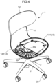
- FIGS. 1 to 3 illustrate an outer appearance of a chair according to the embodiment
- FIGS. 4 and 5 illustrate views in which a part of a seat 1 is omitted.
- a movement mechanism 3 is provided as a movable support between the seat 1 and a leg 2
- a back 4 is attached to move integrally with the seat 1
- arms 5 are attached not to move integrally with the seat 1 and the back 4.
- FIGS. 17 and 18 illustrate a state where the seat 1 is moved in a front-rear direction
- FIG. 22 illustrates a state where the seat 1 is moved in a left-right direction.
- the seat shell 13 includes an inner seat shell 131 attached to a bottom surface of the seat main body 11 and an outer seat shell 132 that backs up the inner seat shell 131 and secures the connection to the movement mechanism 3.
- the leg 2 includes casters 22 at a lower end of a leg vane 21, and a leg support post 23 erected from a center portion of the leg vane 21, and the seat 1 is rotatably attached to an upper end side of the leg support post 23.
- the leg support post 23 can be extended and contracted by a gas spring mechanism GS illustrated in FIG. 6 incorporated therein.
- a reference numeral 24 indicates an operation lever for operating an operated unit 23a of the gas spring mechanism GS.
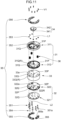
- an upper base unit 31 and a lower base unit 32 are arranged to face each other, the lower base unit 32 is attached to the leg support post 23, and the seat 1 is attached to the upper base unit 31.
- An elastic member 33 is interposed between the upper base unit 31 and the lower base unit 32.
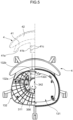
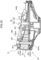
- the periphery of the elastic member 33 is covered with a cover member 6, as illustrated in FIGS. 19 , 20 , 23 , and FIGS. 25A to 25C , but the cover member 6 is omitted in the other drawings. Further, in FIGS. 10 , 13 , and the like, the elastic member 33 is omitted.
- the movement mechanism 3 supports the upper base unit 31 movably with respect to the lower base unit 32, in the front-rear direction as illustrated in FIGS. 19 to 21 , and in the left-right direction as illustrated in FIGS. 21 and 23 , and further in directions of 360 degrees including these directions.
- the upper base unit 31 includes a disk-shaped seat receiver 311 and a disk-shaped upper base plate 312 attached under the seat receiver 311.
- the seat receiver 311 illustrated in FIGS. 7 to 10 , and the like is illustrated as a single body, but the seat receiver 311 is actually integrally formed of a resin together with the outer seat shell 132 in the periphery thereof, as illustrated in FIG. 5 and the like.
- the upper base plate 312 is provided with high nuts 312s, and the seat receiver 311 is provided with boss holes 311s at positions corresponding to the high nuts 312s.
- the upper base plate 312 and the seat receiver 311 are coupled by bolts (not illustrated) inserted through the seat receiver 311 and the high nuts 312s from above.
- the lower base unit 32 includes a disk-shaped support base unit 321 attached to the upper end of the leg support post 23 and a disk-shaped lower base plate 322 attached on the support base unit 321.
- reference numeral 322y indicates an engaging claw provided in the lower base plate 322, and the engaging claw 322y engages with a peripheral edge portion of the support base unit 321 so that the lower base plate 322 and the support base unit 321 are integrated.
- a leg mounting unit 321a into which the leg support post 23 is fitted is provided in a bottom surface of the support base unit 321, and the leg mounting unit 321a is reinforced by ribs 321b extending in a radial direction to increase the rigidity of the leg mounting unit 321a.
- the operated unit 23a used to operate a gas spring is provided at the upper end of the leg support post 23 and in a state where the leg support post 23 is inserted into the leg mounting unit 321a, the operated unit 23a is arranged at a position where the operated unit 23a can be operated by an operation unit 24.
- FIG. 13 is a schematic view of rolling surfaces constituting the movement mechanism 3, in which the elastic member 33 is omitted.
- surfaces of the upper base unit 31 and the lower base unit 32 that face each other in the present embodiment, a facing surface 312a of the upper base plate 312 constituting the upper base unit 31 and a facing surface 322a of the lower base plate 322 constituting the lower base unit 32) form rolling surfaces that roll with respect to each other.
- the rolling surface 322a of the lower base plate 322 is composed of a flat surface
- the rolling surface 312a of the upper base plate 312 is composed of a curved surface that bulges toward the rolling surface 322a of the lower base plate 322
- a contact section between the upper base unit 31 and the lower base unit 32 changes according to a rolling operation, as illustrated by an imaginary line in FIG. 13 .
- the lower base plate 322 may be a curved surface
- the upper base plate 312 may be a flat surface
- both the upper base plate 312 and the lower base plate 322 may be curved surfaces.
- the curved surface has a substantially partial spherical shape or a substantially arc-shaped cross section, in other words, the curved surface has a bowl-shape or a convex R-shape, and the upper base unit 31 may move in directions of 360 degrees including the front-rear, left-right, and diagonal directions, while rolling on the lower base unit 32.
- the curved surface may be implemented in various modes, such as a surface that is curved at a constant curvature, even at a position separated from a reference position N which is a contact position between the two base units 31 and 32 when no load is applied, a surface having a curvature that smoothly changes as the distance from the reference position N increases, a surface having different curvature in the front-rear and left-right directions, and a surface having different curvature between the front and the rear.
- the upper base plate 312 and the lower base plate 322 constitute surfaces (rolling surfaces) 312a and 322a facing each other and moving relative to each other.
- the upper base plate 312 and the lower base plate 322 also serve as mounting members for mounting the cover member 6 for hiding a gap between the rolling surfaces 312a and 322a, as described later with reference to FIGS. 25A to 25C .
- FIGS. 25A to 25C On the other hand, for example, in FIGS.
- the bottom surface of the seat receiver 311 and a top surface of the support base unit 321 may form surfaces (rolling surfaces) facing each other.
- the upper base plate 312 and the lower base plate 322 are not necessarily required.
- the elastic member 33 is attached to the rolling surfaces 312a and 322a in a state where a top surface 33a and a bottom surface 33b contact the rolling surfaces 312a and 322a, respectively, and the elastic member 33 is formed of an elastic resin foam body to form a columnar shape when no load is applied.
- High-elastic urethane foam, low-elastic urethane foam, and the like may be adopted as the elastic resin foam body.
- High-elastic urethane foam instantly deforms upon receiving an external force, and thus exerts a buffering effect.
- Low-elastic urethane foam gradually deforms upon receiving an external force, and thus exerts a delay effect.
- the high-elastic urethane foam is adopted, because high-elastic urethane foam has low temperature dependence and excellent durability. Needlessly to say, low-elastic urethane foam may be used for the elastic member, or a thin member such as an elastic sheet may be used.
- the rolling surface 312a of the upper base plate 312 moves while compressing the elastic member 33 between the rolling surface 312a and the rolling surface 322a of the lower base plate 322, and with this movement, the upper base plate 312 tilts downward in a movement direction.
- a swing operation in which the seat 1 tilts downward in the movement direction according to such a movement of a seated person is realized via the upper base unit 31.
- the movement mechanism a guide mechanism composed of a cam and a follower between an upper base unit and a lower base unit, and a link mechanism connecting the upper base unit and the lower base unit.
- the movement mechanism 3 of the present embodiment utilizes the rolling surfaces 312a and 322a to realize an operation of the seat 1 in which a tilting movement component is larger than a horizontal movement component.
- the chair of the present embodiment that performs such an operation is particularly easy to use in a situation where a person frequently sits down and stands up from a seat.
- the curvatures of the rolling surfaces 312a and 322a are set so that a gravity center position G of the seat 1 is lifted to G' by the movement, as illustrated by a solid line and an imaginary line in FIG. 13 , and the rolling surfaces 312a and 322a constitute a gravity return mechanism GRM that generates, according to a body weight, a return force for returning the seat 1 to the reference position N, which is a position when no load is applied.
- GRM gravity return mechanism
- the movement mechanism 3 is provided with a first connection member 34 that fixes the upper base unit 31 to the lower base unit 32 so that the upper base unit 31 does not separate from the lower base unit 32, and regulates a relative rotation, and a second connection member 35 for imparting a damper function to the movement mechanism 3.
- the damper function is imparted to suppress an abrupt movement of the seat 1, considering that the movement mechanism 3 of the present embodiment performs a rolling operation and high-elastic urethane foam that deforms quickly is adopted as the elastic member 33.
- first holes 31P to 33P for inserting a pin 341 constituting the first connection member 34 are opened along a first line L1
- second holes 31Q to 33Q for inserting a shaft 351 constituting the second connection member 35 are opened along a second line L2.
- the holes 31P, 32P, 33P, 31Q, 32Q, and 33Q prevent the pin 341 and the shaft 351 from interfering with the rolling surfaces 312a and 322a and the elastic member 33, and thus, are also referred to as "relief holes" herein.
- the first connection member 34 is mainly composed of three of the pins 341, and the pins 341 are formed as an integral member with a flange unit 342.
- the pins 341 are inserted through the first hole 31P of the upper base unit 31 (that is, the first hole 31P of the seat receiver 311 and the first hole 31P of the upper base plate 312), the first hole 33P of the elastic member 33, and the first hole 32P of the lower base unit 32 (that is, the first hole 32P of the lower base plate 322), respectively, and the pins 341 are fastened from below by bolts (not illustrated) at positions where the pins 341 abut against the support base unit 321 constituting the lower base unit 32.
- FIG. 19 and the like illustrate the state described above.
- the first holes 31P of the seat receiver 311 are opened at three locations corresponding to the positions of the three pins 341, whereas the first hole 31P of the upper base plate 312 is a large opening for receiving all the three pins 341.
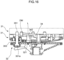
- a relative position (distance L) between the flange unit 342 of the first connection member 34 and the support base unit 321 in FIGS. 16 and 21 is fixed.
- the elastic member 33 is omitted, and the upper base unit 31 descends almost to the maximum extent as illustrated by a solid line and approaches the lower base unit 32.
- the elastic member 33 is interposed and a small load is applied, the upper base unit 31 rises to a position indicated by the imaginary line in FIGS. 16 and 21 .
- the upper base unit 31 When the seat 1 swings in the front-rear direction as illustrated in FIGS. 19 and 20 , or in the left-right direction as illustrated in FIG. 23 , the upper base unit 31 is movable between the flange unit 342 constituting the first connection member 34 and the support base unit 321 (specifically, in a range of the distance L between the flange unit 342 and the lower base plate 322).
- the upper base unit 31 moves while compressing the elastic member 33, and thus, when the applied load is released, the upper base unit 31 rises by a return force of the elastic member 33 as illustrated in FIGS.
- the upper base unit 31 is prevented from rising further at a position where a part of the upper base unit 31 abuts against the flange unit 342.
- the flange unit 342 prevents the upper base unit 31 from being detached upward, and also restricts a tilt angle when the upper base unit 31 is tilted to the front, rear, left, right, or diagonally.
- the flange unit 342 is provided inclined in the front-rear direction, so that a front end 342a is higher than a rear end 342b. That is, as illustrated in FIG. 19 , when the upper base unit 31 tilts forward, the rear end 342b of the flange unit 342 restricts a forward tilt angle of the upper base unit 31, whereas as illustrated in FIG. 20 , when the upper base unit 31 tilts rearward, the front end 342a of the flange unit 342 restricts a rearward tilt angle of the upper base unit 31, and a larger rearward tilt angle than the forward tilt angle is permitted. As illustrated in FIGS.
- a left end 342c and a right end 342d of the flange unit 342 are at the same height position at the left and right, so that inclination of the upper base unit 31 is possible to the left direction and the right direction at the same angle.
- the three pins 341 are each fixed to the support base unit 321, and the pins 341 are inserted through the upper base plate 312 and the seat receiver 311. Therefore, the upper base unit 31 which is a combination of the upper base plate 312 and the seat receiver 311, is prevented from rotating with respect to the lower base unit 32 which is a combination of the support base unit 321 and the lower base plate 322, and the elastic member 33 through which the pins 341 are inserted is also prevented from twisting clockwise or counterclockwise in a plan view. Needlessly to say, the number of pins is not limited to three.
- the second connection member 35 imparts a damper effect to the operation of the movement mechanism 3.
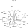
- the second connection member 35 is mainly composed of seven of the shafts 351 which are columnar members, and a damper mechanism DM, which is a braking mechanism, is formed by hole units 311b into which the shafts 351 are inserted and O-rings 353 made of a friction material that are arranged between the shafts 351 and the hole units 311b.
- the hole units 311b correspond to recessed units of ribs provided by forming projections and recesses at a bottom wall of the seat receiver 311 constituting the upper base unit 31, and shaft holes 352 through which the shafts 351 pass are opened at hole bottoms of the hole units 311b. Seven sets of the shafts 351, the hole units 311b, and the O-rings 353 are provided. Needlessly to say, the number of sets is not limited thereto.
- Each of the shafts 351 is a bolt-shaped shaft having a large-diameter proximal end unit 351a at a lower end.
- the proximal end unit 351a is accommodated in a recessed unit 355a of a cocoon-shaped (see FIGS. 11 , 12 , and the like) abutting plate 355 via an elastic plate 354.
- the abutting plate 355 abuts against the bottom surface of the support base unit 321 and is fixed with screws (not illustrated), so that the shafts 351 are attached in a state of protruding upward from the support base unit 321, as illustrated in FIG. 10 .
- the proximal end unit 351a has a spherical or flat spherical shape, and combined with the elastic deformation of the elastic plate 354 interposed between the proximal end unit 351a and the abutting plate 355, the shaft 351 is connected to the support base unit 321 of the lower base unit 32 to be swingable around the proximal end unit 351a. That is, the proximal end unit 351a of the shaft 351, the elastic plate 354, and the recessed unit 355a of the abutting plate 355 form a non-directional joint UJ (see FIG. 14 ). Needlessly to say, another configuration such as a ball joint may be employed as a non-directional joint in which the shaft 351 is swingable around the proximal end.
- the shafts 351 protrude upward via the second hole 32Q of the lower base unit 32 (that is, the second hole 32Q of the support base unit 321 and the second hole 32Q of the lower base plate 322), the second hole 33Q of the elastic member 33 (not illustrated in FIG. 14 ), and the second hole 31Q of the upper base unit 31 (that is, the second hole 31Q of the upper base plate 312 and the second hole (shaft hole) 31Q of the seat receiver 311).
- the shafts 351 constitute the damper mechanism DM.
- a return spring 36 serving as a third connection member is interposed around an outer periphery of the shaft 351 to be interposed between the upper base unit 31 and the lower base unit 32 and connect the upper base unit 31 and the lower base unit 32.
- the return spring 36 is a coil spring.
- a recessed retainer unit 322R that supports a lower end of the return spring 36 in a positioned state is formed on the lower base plate 322 of the lower base unit 32, and the second holes 33Q (R) and 31Q (R) opened at three locations of the elastic member 33 and the upper base plate 312 have a larger diameter than the return spring 36.
- a recessed retainer unit 311R that accommodates an upper end of the return spring 36 in a positioned state is formed in three corresponding locations among the seven locations where the second holes 31Q are provided in the bottom surface of the seat receiver 311 constituting the upper base unit 31.
- the return spring 36 is arranged at a plurality of locations (three locations in the present embodiment) over a range of 180 degrees or more (for example, 270 degrees) around a center position (reference numeral O in FIG. 7 ) of the movement mechanism 3. Therefore, if the upper base unit 31 is tilted in any direction including the front-rear, left-right, and diagonal directions, the return spring 36 on the tilted side is compressed, and the return spring 36 assists the return force for returning the upper base unit 31 to the reference position N when no load is applied.
- the back 4 is integrally attached to the seat 1, and thus, the return spring 36 also supports a load of a movable portion including the seat 1 and the back 4. A structure in which the return spring 36 on the side opposite to the tilted side is pulled may be adopted as the configuration of the return spring 36.
- the second connection member 35 has a configuration in which the O-rings 353 made of a friction material are fitted between the shafts 351, which are columnar members, and the hole units 311b.
- the shaft holes 352 open in a bottom wall 311a of the seat receiver 311 constituting the upper base unit 31, and the periphery of the bottom wall 311a constitutes the hole units 311b that have a tapered shape and open upward.
- a pressing tool 356 has a C-shape in a plan view.
- the pressing tool 356 includes an end unit 356a facing the bottom wall 311a, and a periphery of the end unit 356a constitutes a projecting unit 356b that has a tapered shape and protrudes downward.
- An inner diameter of the O-rings 353 is chosen so that the O-rings 353 fit with the shafts 351 with a predetermined sliding resistance, and the predetermined sliding resistance is chosen so that a required damper effect can be obtained when the seat 1 swings.
- NBR rubber is used for the O-rings 353.
- the material is not limited thereto, and various materials may be adopted as the material for realizing the sliding resistance.
- the shafts 351 are passed through the shaft holes 352 and fitted to the O-rings 353 from above, and the pressing tool 356 is pushed from above to fit the projecting unit 356b into the hole unit 311b.
- the O-rings 353 are pressed against the bottom wall 311a of the seat receiver 311 by the end unit 356a to realize the assembled state illustrated in FIGS. 16 , 20 , and the like.
- the pressing tool 356 is fastened to a top surface of the seat receiver 311 by bolts V1 illustrated in FIGS. 11 , 12 , and the like, so that the O-rings 353 are fixed to the seat receiver 311 and therefore the upper base unit 31, as illustrated in FIG. 7 .
- the O-ring 353 illustrated in FIG. 14 is deformed into a flat elliptical shape, and abuts against the outer periphery of the shaft 351 not at a point, but at a surface having an area of a certain size or more.
- the shafts 351 swing in response to the swinging of the O-rings 353 and follow the change in angle of the upper base unit 31 with respect to the lower base unit 32.
- a relative movement of the hole units 311b and the O-rings 353, which are friction members, with respect to the shafts 351, which are columnar members constituting the damper mechanism DM, is a sliding motion along a longitudinal direction of the shafts 351.
- the shafts 351 may be formed of a bendable and flexible material. In this case, the hole units 311b and the O-rings 353 can move along the longitudinal direction of the shafts 351, without swingably supporting the shafts 351.
- the damper mechanism DM is arranged at a plurality of locations around a center position of the upper base unit 31 over a range of 180 degrees or more (for example, 270 degrees). Therefore, if the seat 1 moves in any direction of 360 degrees, the shafts 351 and the O-rings 353 operate while following the movement of the seat 1 and sliding relative to each other, and exert a damper action by a sliding resistance in both directions of an operation in which a distance between the upper base unit 31 and the lower base unit 32 is expanded or contracted.
- FIGS. 1 to 3 illustrate a state where the seat 1 is in the reference position N.
- the seat 1 of the chair can swing from the reference position N in any direction of 360 degrees including the front-rear, left-right, and diagonal directions, when the upper base plate 312 performs a rolling operation with respect to the lower base plate 322.
- the upper base plate 312 and the lower base plate 322 which are surfaces facing each other, include the first holes 31P and 32P for passing the pins 341 constituting the first connection member as illustrated in FIG. 24 , the second holes 31Q and 32Q for passing the shafts 351 constituting the second connection member as illustrated in FIG. 14 , the recessed retainer unit 322R (see FIGS. 11 and 12 ) for accommodating the return spring 36 which is the third connection member, a return spring insertion hole in the upper base plate 312, and the like.
- the first hole 31P in the upper base plate 312 illustrated in FIG. 24 is a hole having a large opening to avoid interference with the three pins 341, and the second holes 31Q and 32Q illustrated in FIG.
- each of the shafts 351 are provided for each of the shafts 351, so that the number of the second holes 31Q and 32Q is large. As illustrated in FIGS. 11 , 12 , and the like, three of the second holes 31Q and 32Q have a large diameter so that the return spring 36 can also pass through.
- the elastic member 33 is interposed between the above-described region in one of the upper base unit 31 and the lower base unit 32 and a corresponding region in the other one of the upper base unit 31 and the lower base unit 32.
- the elastic member 33 lowers the stability when opening peripheral edges of the holes 31P, 31Q, and the like existing in the rolling surface 312a of the upper base unit 31 abut against the rolling surface 322a of the lower base unit 32 facing the rolling surface 312a, and lowers the stability when opening peripheral edges of the holes 32P and 32Q existing in the rolling surface 322a of the lower base unit 32 abut against the rolling surface 312a of the upper base unit 31 facing the rolling surface 322a.
- the elastic member 33 facilitates rolling between the rolling surfaces 312a and 322a at a place where the curvature of the rolling surfaces 312a and 322a changes and smooths the change of the curvature. Needlessly to say, even in a place where no hole is formed, and also a place where the surface of the rolling surfaces 312a and 322a is irregular or deteriorated, the elastic member has an effect of reducing the rattling caused by the irregular or deteriorated surface.
- the distance between the upper base unit 31 and the lower base unit 32, which are rolling surfaces facing each other, is smaller on the side to which the upper base unit 31 is tilted and larger on the opposite side.
- the elastic member 33 is interposed between the upper base unit 31 and the lower base unit 32, and thus, the elastic member 33 is elastically restored on the larger side and the elastic member 33 is compressed on the smaller side, until a thickness of the elastic member 33 is very small.
- the elastic member 33 accommodates the pins 341 that form the main body of the first connection member 34 and the shafts 351 that form the second connection member 35 in the first holes 33P and the second holes 33Q, and thus the elastic member 33 conceals the pins 341 and shafts 351 as viewed sideways.
- the elastic member 33 does not hide a gap between the upper base unit 31 and the lower base unit 32, and thus, does not include a function of preventing foreign bodies from entering the gap.
- there is no direct or indirect contact there is no direct or indirect contact, however, it is also necessary to hide a region between a pair of swinging surfaces including surfaces facing each other, and thus the circumstance is common.
- the elastic member 33 is arranged at a portion extending from the vicinity of outer peripheral edges 312z and 322z of both swinging surfaces 312a and 322a facing each other to the inside thereof, and a stretchable sheet material 60 is provided between the outer peripheral edges 312z and 322z to conceal a gap between the swinging surfaces 312a and 322a facing each other, including the elastic member 33.
- grooves 312x and 322x extending along the outer peripheral edges 312z and 322z and opening in opposite directions are provided in the vicinity of the outer peripheral edges 312z and 322z of the swinging surfaces 312a and 322a facing each other, and in the cover member 6, deformable strips 61 and 62 are attached to edge portions of the stretchable sheet material 60.
- the strips 61 and 62 are sequentially pushed into the grooves 312x and 322x to be mounted to the grooves 312x and 322x.
- the cover member 6 conceals a gap between the upper base plate 312 and the lower base plate 322, which form facing swinging surfaces.
- the strips 61 and 62 may be mounted to the grooves 312x and 322x in any order.
- the stretchable sheet material 60 is formed by using a material obtained by knitting polyester fibers.
- the stretchable sheet material 60 is sewn or formed into a cylindrical shape, and the strips 61 and 62 made of resin and having an annular thin plate shape are integrally provided at the upper end and the lower end of the stretchable sheet material 60.
- the size and elasticity of the stretchable sheet material 60 are chosen so that no wrinkles are generated when the gap is most narrow and so that the stretchable sheet material 60 does not hinder the operation of the swinging surface when the gap is widened.
- the relationship between the grooves 312x and 322x and the strips 61 and 62 is one-to-one, and each of the strips 61 and 62 corresponds to the entire area of one of the grooves 312x and 322x, and the strips 61 and 62 are provided having a length that surrounds the grooves 312x and 322x.
- the material of the stretchable sheet material 60 is not limited to the above-described materials, and various materials such as cloth, upholstery, woven fabric, and knitted items can be used, as long as the material can be stretched and contracted and covers the inside.
- the stretchable sheet material 60 that can hide the inside is used, but the stretchable sheet material 60 may be a material through which the inside is slightly visible.
- the cover member 6 follows the movement by deforming, in addition to stretching and contracting, according to the movement of the gap between the rolling surfaces 312a and 322a and continues to conceal the gap expanding and contracting between the upper base unit 31 and the lower base unit 32.
- the back 4 is provided with a back main body 42 at an upper end of a back support rod 41, and is attached to the seat 1 to swing together with the seat 1 as described above.
- a rear edge 132a of the outer seat shell 132 is provided with a flat insertion port 132b that opens rearward.
- a lower end front edge 41a of the back support rod 41 constituting the back 4 has a shape in accordance with the rear edge 132a of the outer seat shell 132, and an insertion unit 41b that can be inserted into the insertion port 132b of the outer seat shell 132 is provided.
- the insertion unit 41b is inserted into the insertion port 132b, and then bolts (not illustrated) are inserted into bolt holes 132c and 41c to join the insertion unit 41b and the insertion port 132b.
- a wooden material is used for the back main body 42 of the present embodiment.
- the arms 5 are provided with arm rests 52 at upper ends of an arm rod 51, and are attached not to swing with respect to the seat 1 and the back 4 as described above.
- an arm mounting location 321s is set at a rear portion of the bottom surface of the support base unit 321 where the cocoon-shaped abutting plate 355 is not provided.
- the left and right arm rests 52 are connected by the arm rod 51, and a proximal end of the arm rod 51 is attached to a common bracket 53.
- the bracket 53 is arranged at the arm mounting location 321s, and a bolt (not illustrated) is fastened through a hole 53a of the bracket 53 and a hole 321h provided in the bottom surface of the support base unit 321 from below.
- the arm rod 51 extends from this position to the left or right along the bottom surface of the seat 1, rises upward from the vicinity of the rear edge of the seat 1, and then extends forward.
- the arm rests 52 are arranged at the portions of the arm rod 51 extending forward.
- the chair of the present embodiment includes swinging surfaces (rolling surfaces) 312a and 322a facing each other, and has a configuration in which the swinging surfaces 312a and 322a swings with respect to each other in directions of 360 degrees including the front-rear and left-right directions.
- the elastic member 33 is arranged to be positioned between the swinging surfaces 312a and 322a at least in the vicinity of the outer peripheral edges 312z and 322z, and the stretchable sheet material 60 is provided between the outer peripheral edges 312z and 322z to conceal the gap between the swinging surfaces 312a and 322a facing each other, the gap including the elastic member 33.
- the stretchable sheet material 60 is only arranged between the outer peripheral edges 312z and 322z of the swinging surfaces 312a and 322a facing each other, so that it is possible to conceal only a location that needs to be concealed.
- the elastic member 33 is arranged, in the vicinity of the outer peripheral edges 312z and 322z, between the swinging surfaces 312a and 322a, and the stretchable sheet material 60 conceals a space between the swinging surfaces 312a and 322a, the space including the elastic member 33.
- the stretchable sheet material 60 and the elastic member 33 have a function of preventing foreign bodies from entering the space between the swinging surfaces 312a and 322a, and additionally, the elastic member 33 prevents the stretchable sheet material 60 from loosening or forming wrinkles, and the stretchable sheet material 60 has a function of preventing the elastic member 33 from protruding from the gap.
- the size and elasticity of the stretchable sheet material 60 are chosen so that no wrinkles are generated when the gap is narrow and so that the stretchable sheet material 60 does not hinder the operation of the swinging surfaces 312a and 322a when the gap is wide, and thus, it is possible to maintain an appropriate appearance of the stretchable sheet material 60.
- the stretchable sheet material 60 has a tubular shape, and thus, even if the swinging surfaces 312a and 322a swings with respect to each other in any direction of 360 degrees including the front-rear and left-right directions, the stretchable sheet material 60 can evenly cover the periphery of the gap.
- the cover member 6 can deform to follow the movement of the gap between the swinging surfaces 312a and 322a, and thus, the cover member 6 does not affect the swing operation of the swinging surfaces 312a and 322a facing each other. Further, the cover member 6 has not only the ability of being stretched but also the ability of being deformed, and thus it is possible to realize a state where the movement can be followed more easily.
- the above-described surfaces 312a and 322a facing each other are rolling surfaces that contact each other via the elastic member 33, and in which the surface 312a on the side of the upper base unit 31 is curved and the contact portion between the upper base unit 31 and the lower base unit 32 changes by the swinging. Therefore, it is particularly necessary to prevent an object from being caught between the rolling surfaces 312a and 322a, and thus the cover member 6 having the above-described structure is particularly effective.
- the elastic member 33 may be an annular member positioned only in the vicinity of the outer peripheral edges 312z and 322z of the swinging surfaces 312a and 322a.
- the elastic member 33 is a columnar body that is also arranged at an inner side from the vicinity of the outer peripheral edges 312z and 322z, and thus, the elastic member 33 may be formed thick to effectively achieve the above-described effect.
- the grooves 312x and 322x extending along the outer peripheral edges 312z and 322z and opening in opposite directions are provided in the vicinity of the outer peripheral edges 312z and 322z of the swinging surfaces 312a and 322a facing each other, and the deformable strips 61 and 62 are attached to the edge portions of the stretchable sheet material 60 to form the cover member 6. Further, the strips 61 and 62 are pushed into the grooves 312x and 322x, so that the gap between the swinging surfaces 312a and 322a facing each other is concealed by the cover member 6. Therefore, it is easy to mount the cover member 6 and it is possible to maintain a state where the strips 61 and 62 do not easily detach from the grooves 312x and 322x, during swing.
- each of the grooves 312x and 322x forms a pair together with a different one of the strips 61 and 62, and thus, the strips 61 and 62 can be arranged in a circular shape along the outer peripheral edges 312z and 322z and fitted into the grooves 312x and 322x. Therefore, it is possible to easily attach the cover member 6 and to easily maintain a stereoscopic shape of the cover member 6.
- the chair includes swinging surfaces (rolling surfaces) 312a and 322a facing each other, and has a configuration in which the swinging surfaces 312a and 322a swings with respect to each other in directions of 360 degrees including front-rear and left-right directions.
- an elastic member 33 is arranged to be positioned between the swinging surfaces 312a and 322a at least in the vicinity of outer peripheral edges 312z and 322z, and a stretchable sheet material 60 is provided between the outer peripheral edges 312z and 322z to conceal a gap between the swinging surfaces 312a and 322a facing each other, the gap including the elastic member 33.
Landscapes
- Health & Medical Sciences (AREA)
- Dentistry (AREA)
- General Health & Medical Sciences (AREA)
- Chairs Characterized By Structure (AREA)
- Chair Legs, Seat Parts, And Backrests (AREA)
- Mattresses And Other Support Structures For Chairs And Beds (AREA)
Claims (7)
- Chaise comprenant :des surfaces pivotantes (312a, 322a) se faisant face, les surfaces pivotantes (312a, 322a) oscillant l'une par rapport à l'autre dans une direction de 360 degrés incluant les directions avant-arrière et gauche-droite, dans laquelleun élément élastique (33) est disposé entre les surfaces pivotantes (312a, 322a) au moins à proximité des bords périphériques extérieurs (312z, 322z) des surfaces pivotantes (312a, 322a), et un matériau en feuille étirable (60) est prévu entre les bords périphériques extérieurs (312z, 322z) pour dissimuler un espace entre les surfaces pivotantes (312a, 322a) se faisant face, l'espace incluant l'élément élastique (33) ;caractérisé en ce que
des rainures (312x, 322x) qui s'étendent le long des bords périphériques extérieurs (312z, 322z) des surfaces pivotantes (312a, 322a) se faisant face et qui s'ouvrent dans des directions opposées sont prévues à proximité des bords périphériques extérieurs (312z, 322z) des surfaces pivotantes (312a, 322a), un élément de couverture (6) est formé en attachant des bandes déformables (61, 62) à des parties de bord du matériau en feuille étirable (60), et les bandes (61, 62) sont poussées dans les rainures (312x, 322x) pour dissimuler l'espace entre les surfaces pivotantes (312a, 322a) qui se font face par l'élément de couverture (6). - Chaise selon la revendication 1, dans laquelle une taille et une élasticité du matériau en feuille étirable sont choisis de sorte qu'aucune ride n'est générée lorsque l'espace est étroit et qu'un fonctionnement des surfaces pivotantes (312a, 322a) n'est pas entravé lorsque l'espace est large.
- Chaise selon la revendication 1 ou 2, dans laquelle le matériau en feuille étirable (60) a une forme tubulaire.
- Chaise selon l'une des revendications 1 à 3, dans laquelle l'élément de couverture (6) se déforme pour suivre un mouvement de l'espace entre les surfaces pivotantes (312a, 322a).
- Chaise selon l'une des revendications 1 à 4, dans laquelle les surfaces pivotantes (312a, 322a) qui se font face entrent en contact par l'intermédiaire de l'élément élastique (33), et au moins l'une des surfaces pivotantes (312a, 322a) est une surface de roulement courbée pour changer une portion de contact pendant le pivotement.
- Chaise selon l'une des revendications 1 à 5, dans laquelle l'élément élastique (33) est également disposé sur un côté intérieur à partir du voisinage des bords périphériques extérieurs (312z, 322z) des surfaces pivotantes (312a, 322a).
- Chaise selon la revendication 1, dans laquelle chacune des rainures (312x, 322x) forme une paire avec une extrémité différente des bandes (61, 62).
Applications Claiming Priority (1)
| Application Number | Priority Date | Filing Date | Title |
|---|---|---|---|
| JP2021162893A JP7750705B2 (ja) | 2021-10-01 | 2021-10-01 | 椅子 |
Publications (2)
| Publication Number | Publication Date |
|---|---|
| EP4159089A1 EP4159089A1 (fr) | 2023-04-05 |
| EP4159089B1 true EP4159089B1 (fr) | 2024-07-24 |
Family
ID=83438523
Family Applications (1)
| Application Number | Title | Priority Date | Filing Date |
|---|---|---|---|
| EP22197052.8A Active EP4159089B1 (fr) | 2021-10-01 | 2022-09-22 | Chaise |
Country Status (4)
| Country | Link |
|---|---|
| US (1) | US12114784B2 (fr) |
| EP (1) | EP4159089B1 (fr) |
| JP (1) | JP7750705B2 (fr) |
| CN (1) | CN115919095A (fr) |
Families Citing this family (1)
| Publication number | Priority date | Publication date | Assignee | Title |
|---|---|---|---|---|
| US11766126B1 (en) * | 2022-03-10 | 2023-09-26 | Xuanbin Yang | Highly steady rotary chair |
Family Cites Families (60)
| Publication number | Priority date | Publication date | Assignee | Title |
|---|---|---|---|---|
| US144664A (en) * | 1873-11-18 | Improvement in springs for chairs | ||
| US1358640A (en) * | 1920-07-15 | 1920-11-09 | Spady S Koyama | Ship's chair |
| US2184988A (en) * | 1935-11-27 | 1939-12-26 | Collier Keyworth Company | Chair iron |
| US2132291A (en) * | 1938-02-04 | 1938-10-04 | Fitos Miklos | Spring seat |
| US2796920A (en) * | 1955-02-01 | 1957-06-25 | Gen Tire & Rubber Co | Chair back support |
| US3259431A (en) * | 1964-05-13 | 1966-07-05 | John Gale Company | Seating device |
| US3309137A (en) * | 1966-05-13 | 1967-03-14 | Aaron A Wiebe | Seating arrangement |
| GB1379042A (en) * | 1971-09-29 | 1975-01-02 | Fletcher Bros Castings Ltd | Rocker and swivel device for a seat assembly |
| US3863982A (en) * | 1973-02-05 | 1975-02-04 | Est Company Inc | Tilt-swivel mechanism for a chair |
| DE7531129U (de) * | 1975-10-02 | 1976-03-18 | Schuckmann, Alfred Von, 5657 Haan | Arbeits-sitz |
| US4372606A (en) * | 1980-09-29 | 1983-02-08 | Faull James K | Rocker structure for rocking chairs |
| NO152711C (no) * | 1982-11-17 | 1985-11-06 | Ivar Kalvatn | Anordning for sammenkobling av to i forhold til hverandre bevegelige deler. |
| US4598946A (en) * | 1985-01-02 | 1986-07-08 | Collier-Kenworth Company | Rocking infant seat |
| NO160406C (no) * | 1987-01-23 | 1989-04-19 | Opsvik Peter As | Vippemekanisme, fortrinnsvis for stolsete eller lignende. |
| US4871208A (en) * | 1988-09-06 | 1989-10-03 | Dewey Hodgdon | Chair tilt control mechanism |
| US4974904A (en) * | 1989-10-23 | 1990-12-04 | Phillips E Lakin | Rocking chair apparatus |
| DE4210097C2 (de) * | 1992-03-27 | 2000-05-31 | Josef Gloeckl | Aktivdynamische Sitzvorrichtung |
| US5649740A (en) * | 1995-11-27 | 1997-07-22 | Hodgdon; Dewey | Chair tilt control mechanism |
| US5728049A (en) * | 1996-07-10 | 1998-03-17 | Alberts; Susan | Therapeutic seating apparatus |
| US5769492A (en) * | 1996-12-10 | 1998-06-23 | Jensen; Robert J. | Back saver sport seat |
| JP3131645B2 (ja) * | 1997-11-20 | 2001-02-05 | 博 宇土 | 自動座面傾動椅子 |
| US6176548B1 (en) * | 1998-10-23 | 2001-01-23 | Haworth, Inc. | Tilt mechanism for chair having adjustable spring characteristics |
| US6209958B1 (en) * | 1998-10-23 | 2001-04-03 | Haworth, Inc. | Universal tilt mechanism for a chair |
| US6523895B1 (en) * | 1999-02-05 | 2003-02-25 | Davis Furniture Industries, Inc. | Ergonomic chair |
| US6688689B1 (en) * | 1999-06-24 | 2004-02-10 | Lord Corporation | Multiple degree of freedom seat suspension system |
| US6481795B1 (en) * | 2000-06-05 | 2002-11-19 | Burl Pettibon | Therapeutic chair |
| DE50111943D1 (de) * | 2000-10-12 | 2007-03-15 | Vitra Patente Ag | Lagerung für einen Sitz |
| DE20019569U1 (de) * | 2000-11-17 | 2001-01-11 | Meyer, Stephan, 79100 Freiburg | Sitzvorrichtung für ein Sitzmöbel |
| US6863017B2 (en) * | 2003-03-14 | 2005-03-08 | David Charles | Safety seat for a marine craft or other vehicle |
| DE10311998A1 (de) * | 2003-03-19 | 2004-09-30 | JÄGER, Robert | Therapeutische Sitz- und Liegefläche |
| US20060006704A1 (en) * | 2003-12-15 | 2006-01-12 | Be Aerospace, Inc. | Vehicle seating with storage feature |
| DE202004005366U1 (de) * | 2004-04-05 | 2004-06-24 | VS Vereinigte Spezialmöbelfabriken GmbH & Co. | Stuhl mit Wippmechanik |
| US7547067B2 (en) * | 2004-12-01 | 2009-06-16 | Keilhauer (Partnership) | Tilt and swivel chair and mechanism therefor |
| US7100983B1 (en) * | 2004-12-09 | 2006-09-05 | Gant Richard A | Lumbar flexing seating apparatus |
| US20070102979A1 (en) * | 2005-10-25 | 2007-05-10 | GLOBAL TOTAL OFFICE an Ontario limited partnership having GLOBAL UPHOLSTERY CO. | Adjustment mechanism for a chair and method for replacing a telescoping cylinder in a reconfigurable chair |
| WO2007111428A1 (fr) * | 2006-03-16 | 2007-10-04 | Sung Gil Gang | Chaise d'exercice ventral |
| US20070241599A1 (en) * | 2006-04-17 | 2007-10-18 | Dewey Hodgdon | Chair flexpad support arrangement |
| US7806479B2 (en) * | 2007-02-14 | 2010-10-05 | Wisys Technology Foundation | Seat with adjustable dynamic joint |
| NO327014B1 (no) * | 2007-07-10 | 2009-04-06 | Hag As | Anordning ved vippebeslag for stol |
| JP5124797B2 (ja) | 2007-10-01 | 2013-01-23 | コクヨ株式会社 | 椅子の座 |
| US7922247B2 (en) * | 2008-04-18 | 2011-04-12 | Spark Innovations, Inc. | Hydraulic adjustable seat |
| JP5390127B2 (ja) | 2008-06-16 | 2014-01-15 | 株式会社岡村製作所 | 椅子 |
| DE202008014043U1 (de) * | 2008-10-22 | 2010-03-11 | Tepe-Walser, Silvia | Federweiche Lagerungszwischenstücke |
| US7938489B2 (en) * | 2009-04-15 | 2011-05-10 | Joseph Nazari | Swivel and reclining chair |
| DE202009011135U1 (de) * | 2009-08-14 | 2009-11-05 | Jäger, Edwin | Sitzeinrichtung mit Sicherungsanordnung |
| DE202009017844U1 (de) * | 2009-12-23 | 2010-07-22 | Topstar Gmbh | Kippvorrichtung für einen Stuhl |
| US10226127B2 (en) * | 2010-11-25 | 2019-03-12 | Corechair Incorporated | Resistive support mechanism for a chair including user feedback |
| AU2011334529B2 (en) * | 2010-11-25 | 2016-05-12 | Corechair Incorporated | Resistive support mechanism |
| DE102011101388B3 (de) * | 2011-05-12 | 2012-11-15 | Stephan Meyer | Sitzmöbel |
| US9060612B2 (en) | 2011-05-17 | 2015-06-23 | Rebecca M. Lee | Balance chair |
| DE202012001811U1 (de) * | 2012-02-22 | 2013-05-23 | Andre Bistocchi | Sitzmöbel |
| WO2015003796A1 (fr) * | 2013-07-07 | 2015-01-15 | Bock 1 Gmbh & Co. Kg | Mécanisme pour chaise de bureau |
| US9629465B2 (en) * | 2015-03-18 | 2017-04-25 | Krueger International, Inc. | Lounge chair |
| US9398811B1 (en) * | 2015-03-18 | 2016-07-26 | Krueger International, Inc. | Lounge chair |
| DE102016217992A1 (de) * | 2016-09-20 | 2018-03-22 | VS Vereinigte Spezialmöbelfabriken GmbH & Co. KG | Sitzmöbel |
| WO2019073419A1 (fr) * | 2017-10-11 | 2019-04-18 | Fleetwood Group, Inc. | Tabouret à siège oscillant |
| US11097153B1 (en) * | 2018-06-22 | 2021-08-24 | Gavin Lee | Adjustable balance board |
| EP3701839B1 (fr) * | 2019-02-27 | 2022-11-16 | L&P Property Management Company | Mécanisme de commande pour chaise |
| JP7527857B2 (ja) * | 2020-06-19 | 2024-08-05 | コクヨ株式会社 | 座、椅子および荷重支持体 |
| US11439235B2 (en) * | 2020-10-16 | 2022-09-13 | Artco-Bell Corporation | Seat tilting system |
-
2021
- 2021-10-01 JP JP2021162893A patent/JP7750705B2/ja active Active
-
2022
- 2022-09-16 US US17/946,370 patent/US12114784B2/en active Active
- 2022-09-20 CN CN202211142820.5A patent/CN115919095A/zh active Pending
- 2022-09-22 EP EP22197052.8A patent/EP4159089B1/fr active Active
Also Published As
| Publication number | Publication date |
|---|---|
| JP7750705B2 (ja) | 2025-10-07 |
| US20230103950A1 (en) | 2023-04-06 |
| CN115919095A (zh) | 2023-04-07 |
| JP2023053701A (ja) | 2023-04-13 |
| US12114784B2 (en) | 2024-10-15 |
| EP4159089A1 (fr) | 2023-04-05 |
Similar Documents
| Publication | Publication Date | Title |
|---|---|---|
| EP4159090B1 (fr) | Chaise | |
| US7806478B1 (en) | Task chair with dual tilting capabilities | |
| JP3142518B2 (ja) | 椅 子 | |
| EP4159088B1 (fr) | Chaise | |
| EP4159089B1 (fr) | Chaise | |
| US11202509B2 (en) | Chair | |
| JPWO2020255195A5 (fr) | ||
| EP3643204B1 (fr) | Chaise | |
| JP3080585B2 (ja) | 椅 子 | |
| JP2008012186A (ja) | 椅子 | |
| JPH0245012A (ja) | 背もたれ付椅子 | |
| JP5616133B2 (ja) | 椅子 | |
| JP7385405B2 (ja) | 椅子 | |
| JP5632204B2 (ja) | 椅子 | |
| JP2011092474A (ja) | ロッキング椅子 | |
| JP2020018569A (ja) | 椅子 | |
| KR20200097221A (ko) | 시트 무빙 기능을 가지는 의자 | |
| JPH0252606A (ja) | 背もたれ付椅子 | |
| JP2011092391A (ja) | 椅子 | |
| JP2011255071A (ja) | 椅子 |
Legal Events
| Date | Code | Title | Description |
|---|---|---|---|
| PUAI | Public reference made under article 153(3) epc to a published international application that has entered the european phase |
Free format text: ORIGINAL CODE: 0009012 |
|
| STAA | Information on the status of an ep patent application or granted ep patent |
Free format text: STATUS: THE APPLICATION HAS BEEN PUBLISHED |
|
| AK | Designated contracting states |
Kind code of ref document: A1 Designated state(s): AL AT BE BG CH CY CZ DE DK EE ES FI FR GB GR HR HU IE IS IT LI LT LU LV MC MK MT NL NO PL PT RO RS SE SI SK SM TR |
|
| P01 | Opt-out of the competence of the unified patent court (upc) registered |
Effective date: 20230426 |
|
| STAA | Information on the status of an ep patent application or granted ep patent |
Free format text: STATUS: REQUEST FOR EXAMINATION WAS MADE |
|
| 17P | Request for examination filed |
Effective date: 20230918 |
|
| RBV | Designated contracting states (corrected) |
Designated state(s): AL AT BE BG CH CY CZ DE DK EE ES FI FR GB GR HR HU IE IS IT LI LT LU LV MC MK MT NL NO PL PT RO RS SE SI SK SM TR |
|
| GRAP | Despatch of communication of intention to grant a patent |
Free format text: ORIGINAL CODE: EPIDOSNIGR1 |
|
| STAA | Information on the status of an ep patent application or granted ep patent |
Free format text: STATUS: GRANT OF PATENT IS INTENDED |
|
| INTG | Intention to grant announced |
Effective date: 20240223 |
|
| RIN1 | Information on inventor provided before grant (corrected) |
Inventor name: HAYASHI, KATSUAKI Inventor name: KINOSHITA, YOJIRO Inventor name: SUGANO, TAKAO |
|
| GRAS | Grant fee paid |
Free format text: ORIGINAL CODE: EPIDOSNIGR3 |
|
| GRAA | (expected) grant |
Free format text: ORIGINAL CODE: 0009210 |
|
| STAA | Information on the status of an ep patent application or granted ep patent |
Free format text: STATUS: THE PATENT HAS BEEN GRANTED |
|
| AK | Designated contracting states |
Kind code of ref document: B1 Designated state(s): AL AT BE BG CH CY CZ DE DK EE ES FI FR GB GR HR HU IE IS IT LI LT LU LV MC MK MT NL NO PL PT RO RS SE SI SK SM TR |
|
| REG | Reference to a national code |
Ref country code: GB Ref legal event code: FG4D |
|
| REG | Reference to a national code |
Ref country code: CH Ref legal event code: EP |
|
| REG | Reference to a national code |
Ref country code: IE Ref legal event code: FG4D Ref country code: DE Ref legal event code: R096 Ref document number: 602022004776 Country of ref document: DE |
|
| REG | Reference to a national code |
Ref country code: LT Ref legal event code: MG9D |
|
| REG | Reference to a national code |
Ref country code: NL Ref legal event code: MP Effective date: 20240724 |
|
| PG25 | Lapsed in a contracting state [announced via postgrant information from national office to epo] |
Ref country code: PT Free format text: LAPSE BECAUSE OF FAILURE TO SUBMIT A TRANSLATION OF THE DESCRIPTION OR TO PAY THE FEE WITHIN THE PRESCRIBED TIME-LIMIT Effective date: 20241125 |
|
| REG | Reference to a national code |
Ref country code: AT Ref legal event code: MK05 Ref document number: 1705441 Country of ref document: AT Kind code of ref document: T Effective date: 20240724 |
|
| PG25 | Lapsed in a contracting state [announced via postgrant information from national office to epo] |
Ref country code: NL Free format text: LAPSE BECAUSE OF FAILURE TO SUBMIT A TRANSLATION OF THE DESCRIPTION OR TO PAY THE FEE WITHIN THE PRESCRIBED TIME-LIMIT Effective date: 20240724 |
|
| PG25 | Lapsed in a contracting state [announced via postgrant information from national office to epo] |
Ref country code: PT Free format text: LAPSE BECAUSE OF FAILURE TO SUBMIT A TRANSLATION OF THE DESCRIPTION OR TO PAY THE FEE WITHIN THE PRESCRIBED TIME-LIMIT Effective date: 20241125 Ref country code: NL Free format text: LAPSE BECAUSE OF FAILURE TO SUBMIT A TRANSLATION OF THE DESCRIPTION OR TO PAY THE FEE WITHIN THE PRESCRIBED TIME-LIMIT Effective date: 20240724 |
|
| PG25 | Lapsed in a contracting state [announced via postgrant information from national office to epo] |
Ref country code: NO Free format text: LAPSE BECAUSE OF FAILURE TO SUBMIT A TRANSLATION OF THE DESCRIPTION OR TO PAY THE FEE WITHIN THE PRESCRIBED TIME-LIMIT Effective date: 20241024 |
|
| PG25 | Lapsed in a contracting state [announced via postgrant information from national office to epo] |
Ref country code: FI Free format text: LAPSE BECAUSE OF FAILURE TO SUBMIT A TRANSLATION OF THE DESCRIPTION OR TO PAY THE FEE WITHIN THE PRESCRIBED TIME-LIMIT Effective date: 20240724 Ref country code: GR Free format text: LAPSE BECAUSE OF FAILURE TO SUBMIT A TRANSLATION OF THE DESCRIPTION OR TO PAY THE FEE WITHIN THE PRESCRIBED TIME-LIMIT Effective date: 20241025 Ref country code: PL Free format text: LAPSE BECAUSE OF FAILURE TO SUBMIT A TRANSLATION OF THE DESCRIPTION OR TO PAY THE FEE WITHIN THE PRESCRIBED TIME-LIMIT Effective date: 20240724 |
|
| PG25 | Lapsed in a contracting state [announced via postgrant information from national office to epo] |
Ref country code: BG Free format text: LAPSE BECAUSE OF FAILURE TO SUBMIT A TRANSLATION OF THE DESCRIPTION OR TO PAY THE FEE WITHIN THE PRESCRIBED TIME-LIMIT Effective date: 20240724 |
|
| PG25 | Lapsed in a contracting state [announced via postgrant information from national office to epo] |
Ref country code: LV Free format text: LAPSE BECAUSE OF FAILURE TO SUBMIT A TRANSLATION OF THE DESCRIPTION OR TO PAY THE FEE WITHIN THE PRESCRIBED TIME-LIMIT Effective date: 20240724 |
|
| PG25 | Lapsed in a contracting state [announced via postgrant information from national office to epo] |
Ref country code: IS Free format text: LAPSE BECAUSE OF FAILURE TO SUBMIT A TRANSLATION OF THE DESCRIPTION OR TO PAY THE FEE WITHIN THE PRESCRIBED TIME-LIMIT Effective date: 20241124 Ref country code: AT Free format text: LAPSE BECAUSE OF FAILURE TO SUBMIT A TRANSLATION OF THE DESCRIPTION OR TO PAY THE FEE WITHIN THE PRESCRIBED TIME-LIMIT Effective date: 20240724 |
|
| PG25 | Lapsed in a contracting state [announced via postgrant information from national office to epo] |
Ref country code: HR Free format text: LAPSE BECAUSE OF FAILURE TO SUBMIT A TRANSLATION OF THE DESCRIPTION OR TO PAY THE FEE WITHIN THE PRESCRIBED TIME-LIMIT Effective date: 20240724 |
|
| PG25 | Lapsed in a contracting state [announced via postgrant information from national office to epo] |
Ref country code: ES Free format text: LAPSE BECAUSE OF FAILURE TO SUBMIT A TRANSLATION OF THE DESCRIPTION OR TO PAY THE FEE WITHIN THE PRESCRIBED TIME-LIMIT Effective date: 20240724 Ref country code: RS Free format text: LAPSE BECAUSE OF FAILURE TO SUBMIT A TRANSLATION OF THE DESCRIPTION OR TO PAY THE FEE WITHIN THE PRESCRIBED TIME-LIMIT Effective date: 20241024 |
|
| PG25 | Lapsed in a contracting state [announced via postgrant information from national office to epo] |
Ref country code: RS Free format text: LAPSE BECAUSE OF FAILURE TO SUBMIT A TRANSLATION OF THE DESCRIPTION OR TO PAY THE FEE WITHIN THE PRESCRIBED TIME-LIMIT Effective date: 20241024 Ref country code: PL Free format text: LAPSE BECAUSE OF FAILURE TO SUBMIT A TRANSLATION OF THE DESCRIPTION OR TO PAY THE FEE WITHIN THE PRESCRIBED TIME-LIMIT Effective date: 20240724 Ref country code: NO Free format text: LAPSE BECAUSE OF FAILURE TO SUBMIT A TRANSLATION OF THE DESCRIPTION OR TO PAY THE FEE WITHIN THE PRESCRIBED TIME-LIMIT Effective date: 20241024 Ref country code: LV Free format text: LAPSE BECAUSE OF FAILURE TO SUBMIT A TRANSLATION OF THE DESCRIPTION OR TO PAY THE FEE WITHIN THE PRESCRIBED TIME-LIMIT Effective date: 20240724 Ref country code: IS Free format text: LAPSE BECAUSE OF FAILURE TO SUBMIT A TRANSLATION OF THE DESCRIPTION OR TO PAY THE FEE WITHIN THE PRESCRIBED TIME-LIMIT Effective date: 20241124 Ref country code: HR Free format text: LAPSE BECAUSE OF FAILURE TO SUBMIT A TRANSLATION OF THE DESCRIPTION OR TO PAY THE FEE WITHIN THE PRESCRIBED TIME-LIMIT Effective date: 20240724 Ref country code: GR Free format text: LAPSE BECAUSE OF FAILURE TO SUBMIT A TRANSLATION OF THE DESCRIPTION OR TO PAY THE FEE WITHIN THE PRESCRIBED TIME-LIMIT Effective date: 20241025 Ref country code: FI Free format text: LAPSE BECAUSE OF FAILURE TO SUBMIT A TRANSLATION OF THE DESCRIPTION OR TO PAY THE FEE WITHIN THE PRESCRIBED TIME-LIMIT Effective date: 20240724 Ref country code: ES Free format text: LAPSE BECAUSE OF FAILURE TO SUBMIT A TRANSLATION OF THE DESCRIPTION OR TO PAY THE FEE WITHIN THE PRESCRIBED TIME-LIMIT Effective date: 20240724 Ref country code: BG Free format text: LAPSE BECAUSE OF FAILURE TO SUBMIT A TRANSLATION OF THE DESCRIPTION OR TO PAY THE FEE WITHIN THE PRESCRIBED TIME-LIMIT Effective date: 20240724 Ref country code: AT Free format text: LAPSE BECAUSE OF FAILURE TO SUBMIT A TRANSLATION OF THE DESCRIPTION OR TO PAY THE FEE WITHIN THE PRESCRIBED TIME-LIMIT Effective date: 20240724 |
|
| PG25 | Lapsed in a contracting state [announced via postgrant information from national office to epo] |
Ref country code: RO Free format text: LAPSE BECAUSE OF FAILURE TO SUBMIT A TRANSLATION OF THE DESCRIPTION OR TO PAY THE FEE WITHIN THE PRESCRIBED TIME-LIMIT Effective date: 20240724 Ref country code: SM Free format text: LAPSE BECAUSE OF FAILURE TO SUBMIT A TRANSLATION OF THE DESCRIPTION OR TO PAY THE FEE WITHIN THE PRESCRIBED TIME-LIMIT Effective date: 20240724 Ref country code: DK Free format text: LAPSE BECAUSE OF FAILURE TO SUBMIT A TRANSLATION OF THE DESCRIPTION OR TO PAY THE FEE WITHIN THE PRESCRIBED TIME-LIMIT Effective date: 20240724 |
|
| PG25 | Lapsed in a contracting state [announced via postgrant information from national office to epo] |
Ref country code: MC Free format text: LAPSE BECAUSE OF FAILURE TO SUBMIT A TRANSLATION OF THE DESCRIPTION OR TO PAY THE FEE WITHIN THE PRESCRIBED TIME-LIMIT Effective date: 20240724 Ref country code: EE Free format text: LAPSE BECAUSE OF FAILURE TO SUBMIT A TRANSLATION OF THE DESCRIPTION OR TO PAY THE FEE WITHIN THE PRESCRIBED TIME-LIMIT Effective date: 20240724 |
|
| PG25 | Lapsed in a contracting state [announced via postgrant information from national office to epo] |
Ref country code: CZ Free format text: LAPSE BECAUSE OF FAILURE TO SUBMIT A TRANSLATION OF THE DESCRIPTION OR TO PAY THE FEE WITHIN THE PRESCRIBED TIME-LIMIT Effective date: 20240724 |
|
| REG | Reference to a national code |
Ref country code: DE Ref legal event code: R097 Ref document number: 602022004776 Country of ref document: DE |
|
| PG25 | Lapsed in a contracting state [announced via postgrant information from national office to epo] |
Ref country code: IT Free format text: LAPSE BECAUSE OF FAILURE TO SUBMIT A TRANSLATION OF THE DESCRIPTION OR TO PAY THE FEE WITHIN THE PRESCRIBED TIME-LIMIT Effective date: 20240724 Ref country code: SK Free format text: LAPSE BECAUSE OF FAILURE TO SUBMIT A TRANSLATION OF THE DESCRIPTION OR TO PAY THE FEE WITHIN THE PRESCRIBED TIME-LIMIT Effective date: 20240724 |
|
| PG25 | Lapsed in a contracting state [announced via postgrant information from national office to epo] |
Ref country code: LU Free format text: LAPSE BECAUSE OF NON-PAYMENT OF DUE FEES Effective date: 20240922 |
|
| PLBE | No opposition filed within time limit |
Free format text: ORIGINAL CODE: 0009261 |
|
| STAA | Information on the status of an ep patent application or granted ep patent |
Free format text: STATUS: NO OPPOSITION FILED WITHIN TIME LIMIT |
|
| 26N | No opposition filed |
Effective date: 20250425 |
|
| REG | Reference to a national code |
Ref country code: BE Ref legal event code: MM Effective date: 20240930 |
|
| PG25 | Lapsed in a contracting state [announced via postgrant information from national office to epo] |
Ref country code: BE Free format text: LAPSE BECAUSE OF NON-PAYMENT OF DUE FEES Effective date: 20240930 |
|
| PG25 | Lapsed in a contracting state [announced via postgrant information from national office to epo] |
Ref country code: FR Free format text: LAPSE BECAUSE OF NON-PAYMENT OF DUE FEES Effective date: 20240924 |
|
| PG25 | Lapsed in a contracting state [announced via postgrant information from national office to epo] |
Ref country code: IE Free format text: LAPSE BECAUSE OF NON-PAYMENT OF DUE FEES Effective date: 20240922 |
|
| PG25 | Lapsed in a contracting state [announced via postgrant information from national office to epo] |
Ref country code: SE Free format text: LAPSE BECAUSE OF FAILURE TO SUBMIT A TRANSLATION OF THE DESCRIPTION OR TO PAY THE FEE WITHIN THE PRESCRIBED TIME-LIMIT Effective date: 20240724 |
|
| PGFP | Annual fee paid to national office [announced via postgrant information from national office to epo] |
Ref country code: DE Payment date: 20250730 Year of fee payment: 4 |
|
| PG25 | Lapsed in a contracting state [announced via postgrant information from national office to epo] |
Ref country code: CY Free format text: LAPSE BECAUSE OF FAILURE TO SUBMIT A TRANSLATION OF THE DESCRIPTION OR TO PAY THE FEE WITHIN THE PRESCRIBED TIME-LIMIT; INVALID AB INITIO Effective date: 20220922 |
|
| PG25 | Lapsed in a contracting state [announced via postgrant information from national office to epo] |
Ref country code: HU Free format text: LAPSE BECAUSE OF FAILURE TO SUBMIT A TRANSLATION OF THE DESCRIPTION OR TO PAY THE FEE WITHIN THE PRESCRIBED TIME-LIMIT; INVALID AB INITIO Effective date: 20220922 |
|
| REG | Reference to a national code |
Ref country code: CH Ref legal event code: H13 Free format text: ST27 STATUS EVENT CODE: U-0-0-H10-H13 (AS PROVIDED BY THE NATIONAL OFFICE) Effective date: 20260425 |