EP4159321B1 - Dispositif de fixation de pulvérisateur sur un bras robotisé - Google Patents
Dispositif de fixation de pulvérisateur sur un bras robotisé Download PDFInfo
- Publication number
- EP4159321B1 EP4159321B1 EP22198247.3A EP22198247A EP4159321B1 EP 4159321 B1 EP4159321 B1 EP 4159321B1 EP 22198247 A EP22198247 A EP 22198247A EP 4159321 B1 EP4159321 B1 EP 4159321B1
- Authority
- EP
- European Patent Office
- Prior art keywords
- cover
- flange
- nut
- claws
- deformable
- Prior art date
- Legal status (The legal status is an assumption and is not a legal conclusion. Google has not performed a legal analysis and makes no representation as to the accuracy of the status listed.)
- Active
Links
Images
Classifications
-
- B—PERFORMING OPERATIONS; TRANSPORTING
- B25—HAND TOOLS; PORTABLE POWER-DRIVEN TOOLS; MANIPULATORS
- B25J—MANIPULATORS; CHAMBERS PROVIDED WITH MANIPULATION DEVICES
- B25J15/00—Gripping heads and other end effectors
- B25J15/0019—End effectors other than grippers
-
- B—PERFORMING OPERATIONS; TRANSPORTING
- B05—SPRAYING OR ATOMISING IN GENERAL; APPLYING FLUENT MATERIALS TO SURFACES, IN GENERAL
- B05B—SPRAYING APPARATUS; ATOMISING APPARATUS; NOZZLES
- B05B15/00—Details of spraying plant or spraying apparatus not otherwise provided for; Accessories
- B05B15/14—Arrangements for preventing or controlling structural damage to spraying apparatus or its outlets, e.g. for breaking at desired places; Arrangements for handling or replacing damaged parts
- B05B15/16—Arrangements for preventing or controlling structural damage to spraying apparatus or its outlets, e.g. for breaking at desired places; Arrangements for handling or replacing damaged parts for preventing non-intended contact between spray heads or nozzles and foreign bodies, e.g. nozzle guards
-
- F—MECHANICAL ENGINEERING; LIGHTING; HEATING; WEAPONS; BLASTING
- F16—ENGINEERING ELEMENTS AND UNITS; GENERAL MEASURES FOR PRODUCING AND MAINTAINING EFFECTIVE FUNCTIONING OF MACHINES OR INSTALLATIONS; THERMAL INSULATION IN GENERAL
- F16L—PIPES; JOINTS OR FITTINGS FOR PIPES; SUPPORTS FOR PIPES, CABLES OR PROTECTIVE TUBING; MEANS FOR THERMAL INSULATION IN GENERAL
- F16L19/00—Joints in which sealing surfaces are pressed together by means of a member, e.g. a swivel nut, screwed on, or into, one of the joint parts
- F16L19/06—Joints in which sealing surfaces are pressed together by means of a member, e.g. a swivel nut, screwed on, or into, one of the joint parts in which radial clamping is obtained by wedging action on non-deformed pipe ends
- F16L19/065—Joints in which sealing surfaces are pressed together by means of a member, e.g. a swivel nut, screwed on, or into, one of the joint parts in which radial clamping is obtained by wedging action on non-deformed pipe ends the wedging action being effected by means of a ring
-
- B—PERFORMING OPERATIONS; TRANSPORTING
- B05—SPRAYING OR ATOMISING IN GENERAL; APPLYING FLUENT MATERIALS TO SURFACES, IN GENERAL
- B05B—SPRAYING APPARATUS; ATOMISING APPARATUS; NOZZLES
- B05B13/00—Machines or plants for applying liquids or other fluent materials to surfaces of objects or other work by spraying, not covered by groups B05B1/00 - B05B11/00
- B05B13/02—Means for supporting work; Arrangement or mounting of spray heads; Adaptation or arrangement of means for feeding work
- B05B13/04—Means for supporting work; Arrangement or mounting of spray heads; Adaptation or arrangement of means for feeding work the spray heads being moved during spraying operation
- B05B13/0431—Means for supporting work; Arrangement or mounting of spray heads; Adaptation or arrangement of means for feeding work the spray heads being moved during spraying operation with spray heads moved by robots or articulated arms, e.g. for applying liquid or other fluent material to three-dimensional [3D] surfaces
-
- B—PERFORMING OPERATIONS; TRANSPORTING
- B05—SPRAYING OR ATOMISING IN GENERAL; APPLYING FLUENT MATERIALS TO SURFACES, IN GENERAL
- B05B—SPRAYING APPARATUS; ATOMISING APPARATUS; NOZZLES
- B05B15/00—Details of spraying plant or spraying apparatus not otherwise provided for; Accessories
- B05B15/60—Arrangements for mounting, supporting or holding spraying apparatus
- B05B15/62—Arrangements for supporting spraying apparatus, e.g. suction cups
-
- B—PERFORMING OPERATIONS; TRANSPORTING
- B25—HAND TOOLS; PORTABLE POWER-DRIVEN TOOLS; MANIPULATORS
- B25J—MANIPULATORS; CHAMBERS PROVIDED WITH MANIPULATION DEVICES
- B25J11/00—Manipulators not otherwise provided for
- B25J11/0075—Manipulators for painting or coating
-
- B—PERFORMING OPERATIONS; TRANSPORTING
- B25—HAND TOOLS; PORTABLE POWER-DRIVEN TOOLS; MANIPULATORS
- B25J—MANIPULATORS; CHAMBERS PROVIDED WITH MANIPULATION DEVICES
- B25J15/00—Gripping heads and other end effectors
- B25J15/04—Gripping heads and other end effectors with provision for the remote detachment or exchange of the head or parts thereof
- B25J15/0408—Connections means
- B25J15/045—Connections means having screw means
-
- B—PERFORMING OPERATIONS; TRANSPORTING
- B25—HAND TOOLS; PORTABLE POWER-DRIVEN TOOLS; MANIPULATORS
- B25J—MANIPULATORS; CHAMBERS PROVIDED WITH MANIPULATION DEVICES
- B25J9/00—Program-controlled manipulators
- B25J9/0009—Constructional details, e.g. manipulator supports, bases
-
- F—MECHANICAL ENGINEERING; LIGHTING; HEATING; WEAPONS; BLASTING
- F16—ENGINEERING ELEMENTS AND UNITS; GENERAL MEASURES FOR PRODUCING AND MAINTAINING EFFECTIVE FUNCTIONING OF MACHINES OR INSTALLATIONS; THERMAL INSULATION IN GENERAL
- F16B—DEVICES FOR FASTENING OR SECURING CONSTRUCTIONAL ELEMENTS OR MACHINE PARTS TOGETHER, e.g. NAILS, BOLTS, CIRCLIPS, CLAMPS, CLIPS OR WEDGES; JOINTS OR JOINTING
- F16B39/00—Locking of screws, bolts or nuts
- F16B39/22—Locking of screws, bolts or nuts in which the locking takes place during screwing down or tightening
- F16B39/24—Locking of screws, bolts or nuts in which the locking takes place during screwing down or tightening by means of washers, spring washers, or resilient plates that lock against the object
-
- F—MECHANICAL ENGINEERING; LIGHTING; HEATING; WEAPONS; BLASTING
- F16—ENGINEERING ELEMENTS AND UNITS; GENERAL MEASURES FOR PRODUCING AND MAINTAINING EFFECTIVE FUNCTIONING OF MACHINES OR INSTALLATIONS; THERMAL INSULATION IN GENERAL
- F16B—DEVICES FOR FASTENING OR SECURING CONSTRUCTIONAL ELEMENTS OR MACHINE PARTS TOGETHER, e.g. NAILS, BOLTS, CIRCLIPS, CLAMPS, CLIPS OR WEDGES; JOINTS OR JOINTING
- F16B7/00—Connections of rods or tubes, e.g. of non-circular section, mutually, including resilient connections
- F16B7/04—Clamping or clipping connections
- F16B7/0406—Clamping or clipping connections for rods or tubes being coaxial
- F16B7/0413—Clamping or clipping connections for rods or tubes being coaxial for tubes using the innerside thereof
- F16B7/042—Clamping or clipping connections for rods or tubes being coaxial for tubes using the innerside thereof with a locking element, e.g. pin, ball or pushbutton, engaging in a hole in the wall of at least one tube
Definitions
- the invention relates to the general technical field of spraying devices for coating products, typically robots for painting, coating or lacquering products.
- a sprayer is attached to the end of a robotic arm configured to move the sprayer during a step of coating a part, to coat the surfaces of the part that need to be coated.
- these sprayers are fixed in a removable manner to the robot arm so as to be able to carry out maintenance operations or change the sprayer.
- Well-known sprayer fixing devices therefore offer assemblies using screwed or threaded-tapping assemblies, which make it possible to obtain removable assemblies having a simple design.
- Spraying devices integrating a single nut have been proposed, making it possible to offer a rigid assembly thanks to a significant tightening torque and ease of use making it possible to limit disassembly time, while offering external surfaces easy to clean by encapsulating the functional surfaces to isolate them from the outside.
- US-A-7056387 discloses an electrostatic sprayer that can be mounted on a robot arm and that includes a cover and a nut screwed onto an external thread of the robot arm.
- EP-A-0670448 discloses a rotary coupling device which can be used as part of powering a robot arm equipped with a sprayer.
- EP-A-3222360 discloses a bayonet-type mounting system that is used to mount an air skirt to an air turbine stator, not to attach a sprayer to a robotic arm. This does not resolve the above issue.
- Such a configuration makes it possible, when the helical connection between the nut and the flange loosens due to vibrations, to maintain the mechanical connection between the cover and the flange thanks to the crown. Such a device maintains great speed and ease of use while avoiding the risk of dismantling due to vibrations.
- the invention relates to a spraying robot comprising a fixing device according to the invention.
- the invention relates to a fixing device 1 configured to fix on a robotic arm a sprayer of coating product for coating parts, for example paint, lacquer, coating, glue or any product capable of being sprayed.
- a sprayer of coating product for coating parts for example paint, lacquer, coating, glue or any product capable of being sprayed.
- the fixing device 1 comprises a cover 2 fixed to the sprayer P, a nut 3 to secure the cover 2 and an annular flange 4 provided for fixing on the robotic arm, a crown 5 deformable.
- a support S extends inside the cover 2 and is linked to the sprayer P on the one hand and the flange 4 on the other hand.
- an embodiment not illustrated here has a reverse assembly, and includes a cover fixed to the robot arm and a flange fixed to the sprayer.
- the annular flange 4 is linked to the cover 2 by means of the nut 3.
- the deformable crown 5 is arranged so as to interact with the nut 3 and the flange 4 so as to avoid the separation of the flange 4 and the cover 2 in the event of loosening of the nut 3.
- the cover 2 is fixed to the sprayer P by tightening a screwed connection, and the support S is then compressed between the sprayer P and the flange 4.
- the cover 2 has a substantially cylindrical shape extending along a longitudinal axis X between a first end 20a and a second end 20b.
- the notions of radial and transverse are defined in relation to the longitudinal axis and the cylindrical geometry of the elements. Radially inner means closer to the longitudinal axis X, and radially outer means farther from the longitudinal axis
- the nut 3 has, in the embodiment shown, a substantially cylindrical shape mounted to slide and rotate on the cover 2, radially surrounding the cover 2. It comprises a first helical portion 30, a crown stop 31 configured to provide a stop axial of the crown 5 deformable relative to the nut 3, and a cover stop 32 configured to produce an axial stop of the cover 2 relative to the nut 3.
- the cover stop 32 is arranged at one end of the nut 3 opposite the helical portion 30. In the embodiment shown, the cover stop 32 has a shoulder extending radially towards the inside of the nut 3.
- the cover 2 has an indentation 22 configured to cooperate with a tool allowing the loosening or tightening of the cover 2.
- the second end 20b of the cover 2 has a nut stop 23 configured to cooperate with the cover stop 32 so as to ensure an axial stop between the nut 3 and the cover 2.
- the stop nut 23 has a shoulder extending radially towards the outside of the cover 2.
- the cover 2 has a coupling portion 24, and the nut 3 comprises a second coupling portion 33 complementary to the coupling portion 24 of the cover 2, these coupling portions 24, 33 being configured in such a way that when the cover 2 is moved axially until the coupling portion 24 and the second drive portion 33 interact, these ensure the rotational coupling of the cover 2 and the nut 3.
- This allows the cover to be used 2 to loosen the nut 3 of the flange 4. This is particularly interesting when a tool is used to drive the cover 2 by means of the indentations 22 made on the cover 2.
- the coupling portion 24 and the second coupling portion 33 each comprise a polygonal section produced on a surface respectively of the cover 2 and the nut 3 which are intended to be positioned facing one of the other.
- the coupling portion 24 and the second coupling portion 33 each comprise a mechanical stop ensuring the transmission of a force in a tangential direction, so as to transmit a torque between the cover 2 and the nut 3.
- the helical portion 30 is arranged at one end of the nut 3 to interact with a complementary surface provided on the flange 4 to ensure the assembly of the flange 4 to the nut 3. It is understood in this description, for the sake of simplification, that a helical portion is a surface portion on which a tapping or thread has been provided, with the aim of cooperating with a complementary surface to ensure a helical connection of the screw-nut type.
- the crown stop 31 comprises an annular surface delimited axially by two shoulders.
- the crown stop 31 is arranged on a radially internal surface of the nut 3, and the deformable crown 5 is configured to be located radially internally to the nut 3.
- the stop crown 31 comprises a pin projecting in a radial direction from the nut 3, the pin interacting with a recess made in the deformable crown 5 to ensure the axial stopping of the deformable crown 5 relative to the cover 2.
- the nut 3 is located radially internally to the cover 2
- the deformable crown 5 is configured to be arranged radially externally to the nut 3 and radially internally to the cover 2
- the crown stop 31 is arranged on radially outer surface of nut 3.
- the flange 4 has a substantially annular geometry and comprises centering elements 40, configured to secure in rotation the support S and the flange 4.
- the flange 4 comprises a second helical portion 41 arranged to cooperate with the first helical portion 30 of the nut 1, so as to ensure the assembly and tightening of flange 4 to nut 3.
- the flange 4 further presents an interface portion 42 arranged to interact with the deformable crown 5 and ensure the joining of the flange 4 and the crown 5 even in the event of loosening between the first 30 and the second 41 threaded or tapped portions.
- the interface portion 42 comprises an annular surface 43 extending substantially axially and an axial stop 44 extending radially.
- the deformable crown 5 comprises an annular portion 50 and a deformable portion 51.
- the deformable portion 51 is formed of an elastic material exerting a restoring force when it is deformed in its elastic deformation range.
- the annular portion 50 comprises a stopping element 52 configured to interact with the crown stop 31 of the nut 3, so as to ensure an axial stop of the crown 5 which is deformable relative to the nut 3.
- the stop element 52 comprises a plurality of pins distributed around the periphery of the crown 5, forming a plurality of stops arranged to integrate into the annular portion of the crown stop 31 during assembly.
- a first stop of the crown stop 31 interacts with the crown stop elements 52, and a second stop interacts with an axial end of the crown 5, so as to axially retain the crown 5 relative to the nut 3 in both ways.
- the stopping element comprises a groove or a recess configured to cooperate with a pin or an obstacle made on the nut 3.
- the deformable portion 51 comprises an annular distribution of claws 53 extending substantially longitudinally from the annular portion 50 of the deformable crown 5, moving away from or approaching the longitudinal axis a circle of first diameter D.
- the interface portion 42 of the flange 4 defines a circle of second diameter d, different from the first diameter D.
- the length of the claws 53, the ratio between the first diameter D and the second diameter d and the material of the deformable part 51 are configured so that the claws 53 remain in their elastic deformation range during actuation of the device.
- the claws 53 have at their end a retention element 54, configured to reinforce the retention in axial position of the flange 4 relative to the crown 5.
- This retention portion can include an obstacle, such as a pin, a stop, a claw, or a surface configured to promote friction between the claw 53 and the interface portion 42, for example by a particular profile or a pair of materials promoting friction.
- the claws 53 are formed of a wall portion substantially defining an angular fraction of frustoconical portion, and the retention element 54 is formed of the wall constituting the claw 53, at one end of the claw 53 opposite the annular portion 50.
- the cover 2 presents, at its second end 20b, a disassembly portion 25 having a section of a third diameter configured to interact with the claws 53 of the crown 5 so as to move the claws 53 away from their position to release the interface portion 42 of the flange 4 when the cover 2 is moved axially towards flange 4. This allows flange 4 to be dismantled when cover 2 is moved towards flange 4.
- the cover 2 slides radially internally to the annular portion 50 of the crown 5 and moves the claws 53 away from the longitudinal axis X.
- the third diameter is therefore configured to be greater than the first diameter D, but less than the diameter of the annular portion 50 of the crown 5.
- the third diameter is therefore configured to be less than the first diameter D, but greater than the diameter of the annular portion 50 of the crown 5.
- the length of the claws 53, the ratio between the first diameter D and the third diameter d' and the material of the deformable part 51 are configured so that the claws 53 remain in their elastic deformation range during the actuation of the device 1.
- the retention element 54 comprises a first portion 55 extending radially, a second portion 56 extending substantially axially from the first portion 55, and a third portion 57 extending from the second portion 56 away from or approaching the longitudinal axis
- the first portion 55 is arranged to come into contact with the axial stop 44 of the flange 4 and thus ensure an axial stop between the flange 4 and the crown 5 when the flange 4 is assembled to the nut 3.
- the second portion 56 is arranged to come into contact with the annular surface 43 and thus ensure a radial positioning between the flange 4 and the crown 5 when the flange 4 is assembled to the nut 3.
- the third portion 57 is configured to facilitate the mounting of the flange 4 in the crown 5.
- the second portion 56 is positioned radially externally with respect to the annular bearing surface 43, the third portion 57 extends away from the longitudinal axis X.
- the third portion 57 is configured in such a way that its end is further from the longitudinal axis All of the thirds portions 57 therefore form a guide for the interface portion 42, which allows, during assembly, to spread the claws 53 by pressure on the flange 4, which greatly facilitates assembly.
- the interface portion 42 also includes a guide portion 45 configured to present an inclination substantially equivalent to that of the third portions 57, so as, during assembly, to separate the claws 57 by cooperating with the third portions, which limits the risks of damaging the claws 53 by compressing them instead of moving them radially.
- the finger 53 is configured in such a way that during assembly the second portion 56 is positioned radially internally relative to the annular bearing surface 43, the third portion 57 extending towards the longitudinal axis
- the third portion 57 is configured in such a way that its end is closer to the longitudinal axis X than half of the second diameter d.
- one or more recesses 58 are provided through the crown 5. This makes it possible to reduce the stiffness of the crown 5 and increasing its capacity to deform radially, which makes it possible to facilitate the assembly of crown 5 on nut 3.
- the cover 2 has, on the disassembly portion 25, a softened edge 26, for example by means of a fillet or a chamfer, to avoid contact between a sharp edge and the claws 53 during disassembly of the device, and thus limit the wear of the claws 53.
- the cover 2 has, at its first end 20a, a third helical portion 21 arranged to interact with a complementary portion on the sprayer P for fixing the device 1 on the sprayer P.
- the third helical portion 21 has an inverted pitch relative to the pitch of the first helical portion 30. This makes it possible to avoid loosening the connection between the sprayer P and the cover 2 when tightening the nut 3. In addition, this facilitates disassembly, since it is not necessary to cause the cover 2 to rotate. only in one direction to ensure the dismantling of device 1.
- the respective axial positions of the coupling portion 24, the disassembly portion 25, the second coupling portion 33, the stop crown 31, and the claws 53 are all configured to allow the cover 2 to be positioned relative to the nut 3 so as to simultaneously ensure the interaction between the coupling portion 24 and the second coupling portion 33 on the one hand , and the disassembly portion 25 and the claws 53 on the other hand.
- first axial distance A between the coupling portion 24 and the disassembly portion 25 equal to a second axial distance B between the second coupling portion 33 and the claws 53.
- the second distance axial B corresponds to the sum of the distance between the second coupling portion 33 and the crown stop 31 and the distance between the stop element 52 and the claws 53, more precisely a straight section of the claws at which the distance between the claw and the longitudinal axis X is equivalent to half a third diameter of.
- the crown 5 comprises 6 claws 53, each of the claws forming an angular fraction of frustoconical portion, the claws 53 being separated from each other by grooves.
- Such an embodiment makes it possible to increase the rigidity of each of the claws compared to an embodiment in which the crown contains more claws 53, while preserving the mobility of the claws 53 when they are moved by the disassembly portion 25. This makes it possible to improve the holding of the flange 4 by the claws 53.
- the user mounts the nut 3 on the cover 2 so as to bring the cover 2 into the stop position by bringing the cover into contact hood stop 32 and nut stop 23.
- the crown 5 is then assembled to the nut 3, the cooperation of the crown stop 31 and the stop element 51 making it possible to ensure that the crown 5 is maintained in position relative to the nut 3.
- the flange 4 is then assembled to the nut 3 by means of the helical portions.
- the claws 53 of the crown 5 are spaced from the longitudinal axis X by the interaction of the interface element 42 and the third portions 57, then close when the relative axial position of the flange 4 and the nut 3 allows this, that is to say when the first portions 55 coincide axially with the axial stop 44 of the flange 4.
- Tightening by force can be carried out by placing the cover 2 axially relative to the nut 3 in such a way that the coupling portion 25 of the cover 2 and the second coupling portion 33 cooperate, so as to tighten the nut 3 on the flange 4 by applying a torque to the cover 2.
- a tool can be used with the indentations 22 of the cover 2 to apply a significant tightening torque.
- the cover 2 is then moved axially towards the sprayer P to tighten it to the sprayer P by means of the third helical portion 21.
- the support S maintains the axial spacing between the flange 4 and the sprayer, which allows the tightening of the cover 2 to ensure contact between the nut stop 23 and the cover stop 32, and thus ensure the fixing of the sprayer P to the robotic arm.
- the cover 2 When disassembling the device 1, the cover 2 is unscrewed from the sprayer P then brought into an axial position allowing both the claws 53 to be separated, thus releasing the interface portion 42 of the flange 4, and also allowing the coupling portion 25 of the cover 2 and the second coupling portion 33 to cooperate. This therefore allows flange 4 to be released and nut 3 to be loosened in a single operation.
Landscapes
- Engineering & Computer Science (AREA)
- Mechanical Engineering (AREA)
- Robotics (AREA)
- General Engineering & Computer Science (AREA)
- Manipulator (AREA)
- Spray Control Apparatus (AREA)
- Mutual Connection Of Rods And Tubes (AREA)
- Details Or Accessories Of Spraying Plant Or Apparatus (AREA)
Description
- L'invention concerne le domaine technique général des appareils de pulvérisation pour le revêtement de produits, typiquement des robots permettant de peindre, d'enduire ou de laquer des produits.
- Classiquement, dans des lignes de production de grande série, les opérations d'enduction, de revêtement ou de peinture sont réalisées au moyen d'appareils de pulvérisation montés sur des bras robotisés. Un pulvérisateur est fixé à l'extrémité d'un bras robotisé configuré pour déplacer le pulvérisateur au cours d'une étape d'enduction d'une pièce, afin de recouvrir les surfaces de la pièce qui doivent l'être.
- Classiquement, ces pulvérisateurs sont fixés de manière démontable au bras de robot de manière à pouvoir effectuer des opérations de maintenance ou un changement de pulvérisateur. Des dispositifs de fixation de pulvérisateurs bien connus proposent donc des assemblages utilisant des ensemble vissés, ou filetage-taraudage, qui permettent d'obtenir des assemblages démontables présentant une conception simple.
- Les opérations de maintenance ou de changement de pulvérisateur impliquant nécessairement l'arrêt du robot, il est avantageux de limiter au maximum le temps de démontage du pulvérisateur, et donc de limiter le nombre d'ensembles vissés permettant de fixer le pulvérisateur au bras robot. En outre, en milieu de pulvérisation de peinture, des particules de peinture en suspension peuvent s'accumuler sur les surfaces exposées au milieu extérieur, et encrasser les éléments exposés. Il est donc particulièrement intéressant de ne laisser que des surfaces lisses exposées à l'extérieur, et de couvrir autant que possible les éléments de fixation permettant l'assemblage du pulvérisateur au bras robotisé. Des dispositifs de pulvérisation intégrant un unique écrou ont été proposés, permettant de proposer un assemblage rigide grâce à un couple de serrage important et une facilité d'utilisation permettant de limiter le temps de démontage, tout en proposant des surface externes faciles à nettoyer en encapsulant les surfaces fonctionnelles pour les isoler de l'extérieur.
- Par exemple,
US-A-7056387 divulgue un pulvérisateur électrostatique qui peut être monté sur un bras de robot et qui comprend un capot et un écrou vissé sur un filetage externe du bras de robot. - Toutefois, au cours des cycles d'utilisation, les vibrations provoquées par le fonctionnement du robot et du pulvérisateur sont transmises aux ensembles filetage-taraudage et provoquent le desserrement de ceux-ci, pouvant parfois mener à une désolidarisation du pulvérisateur et du bras robot.
-
EP-A-0670448 divulgue un dispositif de couplage rotatif qui peut être utilisé dans le cadre de l'alimentation d'un bras robot équipé d'un pulvérisateur.EP-A-3222360 divulgue un système de montage de type baïonnette qui est utilisé pour monter une jupe d'air sur un stator de turbine à air, pas pour fixer un pulvérisateur sur bras robotisé. Ceci ne permet pas de régler le problème ci-dessus. - Il existe donc un besoin d'amélioration des systèmes d'assemblage de pulvérisateurs sur les bras robots, qui soit simple et rapide d'utilisation et évite les risques de démontage à cause des vibrations.
- Afin d'assurer l'assemblage d'un dispositif de pulvérisation sur un bras robot, l'invention propose un dispositif de fixation configuré pour fixer un pulvérisateur de produit pour l'enduction de pièces sur un bras robotisé, le dispositif de fixation comportant :
- un capot configuré pour être fixé à un parmi le pulvérisateur et le bras robotisé, présentant une forme sensiblement cylindrique s'étendant selon un axe longitudinal,
- un écrou monté à coulissement et à rotation sur le capot, comportant une première portion hélicoïdale, et un arrêt de capot configuré pour arrêter axialement l'écrou par rapport au capot,
- une bride configurée pour être fixée à un autre parmi le pulvérisateur et le bras robotisé, comportant une deuxième portion hélicoïdale arrangée pour coopérer avec la première portion hélicoïdale de l'écrou,
- caractérisé en ce que le dispositif comporte en outre une couronne déformable montée sur l'écrou, la couronne comprenant une portion déformable et une portion annulaire, la portion annulaire présentant au moins un élément d'arrêt configuré pour interagir avec un arrêt de couronne formé sur l'écrou de manière à assurer un arrêt axial de la couronne par rapport à l'écrou,
- et en ce que la bride comporte une portion d'interface agencée pour interagir avec la couronne déformable de telle manière que, lors du serrage de l'écrou de manière à verrouiller la bride au capot, la portion déformable se déforme pour interagir avec la portion d'interface de la bride pour assurer une liaison entre la bride et la couronne.
- Une telle configuration permet, lorsque la liaison hélicoïdale entre l'écrou et la bride se desserre à cause des vibrations, de maintenir la liaison mécanique entre le capot et la bride grâce à la couronne. Un tel dispositif garde une grande rapidité et facilité d'utilisation tout en évitant les risques de démontage à cause des vibrations.
- Optionnellement mais avantageusement, l'invention présente les caractéristiques suivantes, prises seules ou en combinaison :
- le capot présente une portion de couplage, et l'écrou comporte une deuxième portion de couplage complémentaire à la portion de couplage du capot, de manière à pouvoir sélectivement coupler en rotation selon l'axe longitudinal le capot et l'écrou ; cela permet de desserrer l'écrou en appliquant un effort de rotation sur le capot ;
- le capot présente sur une surface extérieure au moins une empreinte adaptée pour coopérer avec un outil ; cela permet d'appliquer un couple important au capot, et ainsi d'améliorer le serrage ;
- le capot présente une troisième portion hélicoïdale agencée pour interagir avec une portion complémentaire sur le bras de robot pour la fixation du dispositif sur le bras robot, la troisième portion hélicoïdale présentant un pas inversé par rapport au pas de la première portion hélicoïdale ; cela permet d'éviter le desserrage de la liaison entre le pulvérisateur et le capot lors du serrage de l'écrou ;
- le capot est agencé pour pourvoir, lors du démontage de la bride, interagir avec la portion déformable de la couronne déformable de manière à libérer la liaison entre la couronne et la bride ; cela permet, en manipulant le capot, de libérer la bride et ainsi faciliter le démontage du dispositif.
- la portion déformable de la couronne déformable présente une distribution annulaire de griffes s'étendant sensiblement longitudinalement depuis la portion annulaire de la couronne déformable en s'écartant ou se rapprochant de l'axe longitudinal, de telle manière que les extrémités des griffes définissent un cercle d'un premier diamètre, la portion d'interface de la bride définit un cercle d'un deuxième diamètre, différent du premier diamètre, le premier diamètre et le deuxième diamètre et les griffes étant configurés de telle sorte que les griffes restent dans leur domaine de déformation élastique pendant l'actionnement du dispositif ; cela permet de faciliter le montage du dispositif en évitant le besoin d'utiliser un outil, grâce à l'utilisation d'un élément déformable exerçant un effort de rappel assurant le montage ;
- le premier diamètre est inférieur au deuxième diamètre ;
- le capot comporte une première extrémité et une deuxième extrémité, et une portion de démontage agencée au niveau de la deuxième extrémité, la portion de démontage présentant une section d'un troisième diamètre configuré pour interagir avec les griffes de la couronne de manière à écarter les griffes de leur position pour libérer la portion d'interface de la bride lorsque le capot est déplacé axialement vers la bride ;
- la portion de couplage et la portion de démontage sont distantes d'une première distance axiale, et dans lequel la deuxième portion de couplage et les griffes sont distantes d'une deuxième distance axiale, la première distance axiale étant égale à la deuxième distance axiale ; cela permet, lors du démontage, d'utiliser le capot pour simultanément écarter les griffes pour libérer la bride et entraîner en rotation l'écrou pour desserrer la bride, ce qui facilite grandement le démontage du dispositif.
- Selon un deuxième aspect, l'invention concerne un robot de pulvérisation comprenant un dispositif de fixation selon l'invention.
- D'autres caractéristiques et avantages de l'invention ressortiront clairement de la description qui en est donnée ci-dessous, à titre indicatif et nullement limitatif, en référence aux figures suivantes :
- La
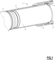
figure 1 est une représentation en coupe partielle des différentes pièces permettant de mettre en oeuvre un dispositif de fixation selon l'invention, qui illustre donc un capot en coupe, un écrou en coupe, une couronne déformable en coupe, une bride de fixation au robot en coupe, un châssis de pulvérisateur et un arbre interne ; - La
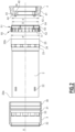
figure 2 est une représentation de profil des éléments composant un dispositif de fixation selon l'invention, illustrant un écrou en coupe, un capot, une couronne en coupe et une bride en coupe ; - La
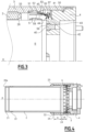
figure 3 est une représentation de profil des éléments composant un dispositif de fixation selon l'invention, illustrant un écrou en coupe, un capot, une couronne en coupe, une bride en coupe et un arbre interne ; - La
figure 4 est une représentation de profil d'un dispositif de fixation selon l'invention, illustrant un écrou en coupe, un capot en coupe, une couronne en coupe et une bride en coupe, permettant d'illustrer un premier mode de réalisation de la couronne ; - Les
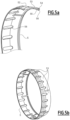
figures 5a et 5b représentent un deuxième mode de réalisation de la couronne, lafigure 5a représentant une coupe partielle de la couronne de manière à détailler le profil de la couronne, lafigure 5b représentant la couronne entière. - Pour plus de clarté, les éléments identiques ou similaires sont repérés par des signes de référence identiques sur l'ensemble des figures.
- L'invention concerne un dispositif 1 de fixation configuré pour fixer sur un bras robotisé un pulvérisateur de produit de revêtement pour l'enduction de pièces, par exemple de la peinture, une laque, un enduit, une colle ou tout produit susceptible d'être pulvérisé.
- En référence à la
figure 1 , dans un mode de réalisation de l'invention, le dispositif 1 de fixation comporte un capot 2 fixé au pulvérisateur P, un écrou 3 pour solidariser le capot 2 et une bride 4 annulaire prévue pour la fixation sur le bras robotisé, une couronne 5 déformable. Un support S s'étend à l'intérieur du capot 2 et est lié au pulvérisateur P d'une part et la bride 4 d'autre part. - Il est évident qu'un mode de réalisation non illustré ici présente un montage inverse, et comprend un capot fixé au bras robot et une bride fixée au pulvérisateur.
- Lors de la fixation du pulvérisateur P au bras robot, la bride 4 annulaire est liée au capot 2 au moyen de l'écrou 3. La couronne 5 déformable est disposée de manière à interagir avec l'écrou 3 et la bride 4 de manière à éviter la désolidarisation de la bride 4 et du capot 2 en cas de desserrage de l'écrou 3. Le capot 2 est fixé au pulvérisateur P par serrage d'une liaison vissée, et le support S est alors compressé entre le pulvérisateur P et la bride 4.
- En référence à la
figure 2 , le capot 2 présente une forme sensiblement cylindrique s'étendant selon un axe longitudinal X entre une première extrémité 20a et une deuxième extrémité 20b. Dans cette demande, les notions de radial et de transversal sont définis par rapport à l'axe longitudinal et la géométrie cylindrique des éléments. Radialement intérieur signifie plus près de l'axe longitudinal X, et radialement extérieur signifie plus loin de l'axe longitudinal X. L'écrou 3, la bride 4 et la couronne 5 présentent une géométrie de révolution selon l'axe longitudinal X. - L'écrou 3 présente dans le mode de réalisation représenté une forme sensiblement cylindrique monté à coulissement et à rotation sur le capot 2, entourant radialement le capot 2. Il comporte une première portion hélicoïdale 30, un arrêt de couronne 31 configuré pour réaliser un arrêt axial de la couronne 5 déformable par rapport à l'écrou 3, et un arrêt de capot 32 configuré pour réaliser un arrêt axial du capot 2 par rapport à l'écrou 3. L'arrêt de capot 32 est agencé à une extrémité de l'écrou 3 opposée à la portion hélicoïdale 30. Dans le mode de réalisation représenté, l'arrêt de capot 32 comporte un épaulement s'étendant radialement vers l'intérieur de l'écrou 3.
- Avantageusement, le capot 2 présente une empreinte 22 configurée pour coopérer avec un outil permettant le desserrage ou le serrage du capot 2.
- La deuxième extrémité 20b du capot 2 présente un arrêt d'écrou 23 configurée pour coopérer avec l'arrêt de capot 32 de manière à assurer un arrêt axial entre l'écrou 3 et le capot 2. Dans ce mode de réalisation, l'arrêt d'écrou 23 comporte un épaulement s'étendant radialement vers l'extérieur du capot 2.
- Avantageusement, le capot 2 présente une portion de couplage 24, et l'écrou 3 comporte une deuxième portion de couplage 33 complémentaire à la portion de couplage 24 du capot 2, ces portions de couplage 24, 33 étant configurées de telle manière que lorsque le capot 2 est déplacé axialement jusqu'à ce que la portion de couplage 24 et la deuxième 33 portion d'entrainement interagissent, celles-ci assurent le couplage en rotation du capot 2 et de l'écrou 3. Cela permet d'utiliser le capot 2 pour desserrer l'écrou 3 de la bride 4. C'est particulièrement intéressant lorsqu'un outil est utilisé pour entraîner le capot 2 au moyen des empreintes 22 ménagées sur le capot 2.
- Dans le mode de réalisation représenté, la portion de couplage 24 et la deuxième portion de couplage 33 comportent chacune une section polygonale réalisée sur une surface respectivement du capot 2 et de l'écrou 3 qui sont destinées à être positionnées en regard l'une de l'autre. En variante, la portion de couplage 24 et la deuxième portion de couplage 33 comportent chacune une butée mécanique assurant la transmission d'un effort dans une direction tangentielle, de manière à transmettre un couple entre le capot 2 et l'écrou 3.
- La portion hélicoïdale 30 est agencée à une extrémité de l'écrou 3 pour interagir avec une surface complémentaire ménagée sur la bride 4 pour assurer l'assemblage de la bride 4 à l'écrou 3. Il est entendu dans cette description, par souci de simplification, qu'une portion hélicoïdale est une portion de surface sur laquelle a été ménagée un taraudage ou un filetage, dans le but de coopérer avec une surface complémentaire pour assurer une liaison hélicoïdale de type vis-écrou.
- L'arrêt de couronne 31 comprend une portée annulaire délimitée axialement par deux épaulements. Dans le mode de réalisation représenté, l'arrêt de couronne 31 est agencé sur une surface radialement interne de l'écrou 3, et la couronne 5 déformable est configurée pour être située radialement intérieurement à l'écrou 3. En variante, l'arrêt de couronne 31 comporte un pion faisant saillie dans une direction radiale depuis l'écrou 3, le pion interagissant avec un évidement réalisé dans la couronne 5 déformable pour assurer l'arrêt axial de la couronne 5 déformable par rapport au capot 2.
- En variante non représentée, l'écrou 3 se situe radialement intérieurement au capot 2, la couronne 5 déformable est configurée pour être agencée radialement extérieurement à l'écrou 3 et radialement intérieurement au capot 2, et l'arrêt de couronne 31 est agencé sur surface radialement externe de l'écrou 3.
- La bride 4 présente une géométrie sensiblement annulaire et comporte des éléments de centrage 40, configurée pour solidariser en rotation le support S et la bride 4. La bride 4 comporte une deuxième portion hélicoïdale 41 arrangée pour coopérer avec la première portion hélicoïdale 30 de l'écrou 1, de manière à assurer l'assemblage et le serrage de la bride 4 à l'écrou 3.
- La bride 4 présente en outre une portion d'interface 42 agencée pour interagir avec la couronne 5 déformable et assurer la solidarisation de la bride 4 et la couronne 5 même en cas de desserrage entre la première 30 et la deuxième 41 portions filetées ou taraudées. Dans le mode de réalisation représenté, la portion d'interface 42 comporte une portée annulaire 43 s'étendant sensiblement axialement et une butée axiale 44 s'étendant radialement.
- La couronne 5 déformable comporte une portion annulaire 50 et une portion déformable 51. La portion déformable 51 est formée d'un matériau élastique exerçant un effort de rappel lorsqu'il est déformé dans son domaine de déformation élastique. La portion annulaire 50 comporte un élément d'arrêt 52 configuré pour interagir avec l'arrêt de couronne 31 de l'écrou 3, de manière à assurer un arrêt axial de la couronne 5 déformable par rapport à l'écrou 3. Dans le mode de réalisation représenté, l'élément d'arrêt 52 comporte une pluralité de pions répartis sur le pourtour de la couronne 5, formant une pluralité de butées agencées pour s'intégrer dans la portion annulaire de l'arrêt de couronne 31 lors du montage. Une première butée de l'arrêt de couronne 31 interagit avec les éléments d'arrêt 52 de couronne, et une deuxième butée interagit avec une extrémité axiale de la couronne 5, de manière à retenir axialement la couronne 5 par rapport à l'écrou 3 dans les deux sens. En variante non représentée, l'élément d'arrêt comporte une rainure ou un évidement configuré pour coopérer avec un pion ou un obstacle réalisé sur l'écrou 3.
- La portion déformable 51 comporte une distribution annulaire de griffes 53 s'étendant sensiblement longitudinalement depuis la portion annulaire 50 de la couronne déformable 5 en s'écartant ou se rapprochant de l'axe longitudinal X, de telle manière que les extrémités des griffes 53 définissent un cercle de premier diamètre D. La portion d'interface 42 de la bride 4 définit un cercle de deuxième diamètre d, différent du premier diamètre D. Ainsi, lors du montage, les griffes 53 sont déformées de manière à les écarter de leur position de repos, la bride 4 est positionnée axialement de sorte que la portion d'interface 42 et les extrémités des griffes 53 coïncident axialement, et les griffes 53 sont relâchées. L'effort de rappel exercé par les griffes 53 leur permet de revenir vers leur position initiale de manière à interagir avec la portion d'interface 42. Le rapport entre les premier D et deuxième d diamètres est configuré de telle sorte que les griffes 53 exercent un effort assurant le maintien de la bride 4 même lors du desserrage des première 30 et deuxième 41 portions filetées ou taraudées.
- La longueur des griffes 53, le rapport entre le premier diamètre D et le deuxième diamètre d et le matériau de la partie déformable 51 sont configurés pour que les griffes 53 restent dans leur domaine de déformation élastique pendant l'actionnement du dispositif.
- Avantageusement, les griffes 53 présentent à leur extrémité un élément de rétention 54, configurée pour renforcer le maintien en position axiale de la bride 4 par rapport à la couronne 5. Cette portion de rétention peut comprendre un obstacle, comme un pion, une butée, une griffe, ou une surface configurée pour favoriser le frottement entre la griffe 53 et la portion d'interface 42, par exemple par un profil particulier ou un couple de matériaux favorisant le frottement.
- Dans le mode de réalisation représenté, les griffes 53 sont formées d'une portion de paroi définissant sensiblement une fraction angulaire de portion tronconique, et l'élément de rétention 54 est formé de la paroi constituant la griffe 53, à une extrémité de la griffe 53 opposée à la portion annulaire 50.
- Le capot 2 présente, au niveau de sa deuxième extrémité 20b, une portion de démontage 25 présentant une section d'un troisième diamètre d' configuré pour interagir avec les griffes 53 de la couronne 5 de manière à écarte les griffes 53 de leur position pour libérer la portion d'interface 42 de la bride 4 lorsque le capot 2 est déplacé axialement vers la bride 4. Cela permet de démontage de la bride 4 lorsque le capot 2 est déplacé vers la bride 4.
- Dans le mode de réalisation représenté, le capot 2 coulisse radialement intérieurement à la portion annulaire 50 de la couronne 5 et éloigne les griffes 53 de l'axe longitudinal X. Le troisième diamètre d'est donc configuré pour être supérieur au premier diamètre D, mais inférieur au diamètre de la portion annulaire 50 de la couronne 5.
- Dans une variante dans laquelle le capot 2 coulisse radialement extérieurement à la portion annulaire 50 de la couronne 5, et rapproche donc les griffes 53 de l'axe longitudinal X, le troisième diamètre d'est donc configuré pour être inférieur au premier diamètre D, mais supérieur au diamètre de la portion annulaire 50 de la couronne 5.
- La longueur des griffes 53, le rapport entre le premier diamètre D et le troisième diamètre d' et le matériau de la partie déformable 51 sont configurés pour que les griffes 53 restent dans leur domaine de déformation élastique pendant l'actionnement du dispositif 1.
- En référence à la
figure 3 , l'élément de rétention 54 comporte une première portion 55 s'étendant radialement, une deuxième portion 56 s'étendant sensiblement axialement depuis la première portion 55, et une troisième portion 57 s'étendant depuis la deuxième portion 56 en s'écartant ou se rapprochant de l'axe longitudinal X. - La première portion 55 est agencée pour venir au contact de la butée axiale 44 de la bride 4 et ainsi assurer un arrêt axial entre la bride 4 et la couronne 5 lorsque la bride 4 est assemblée à l'écrou 3.
- La deuxième portion 56 est agencée pour venir au contact de la portée annulaire 43 et ainsi assurer une mise en position radiale entre la bride 4 et la couronne 5 lorsque la bride 4 est assemblée à l'écrou 3.
- La troisième portion 57 est configurée pour faciliter le montage de la bride 4 dans la couronne 5. A cet effet, dans le mode de réalisation représenté, la deuxième portion 56 est positionnée radialement extérieurement par rapport à la portée annulaire 43, la troisième portion 57 s'étend en s'éloignant de l'axe longitudinal X. La troisième portion 57 est configurée de telle manière que son extrémité est plus éloignée de l'axe longitudinal X que la moitié du deuxième diamètre d. L'ensemble des troisièmes portions 57 forme donc un guide pour la portion d'interface 42, qui permet, lors du montage, d'écarter les griffes 53 par pression sur la bride 4, ce qui facilite grandement le montage.
- La portion d'interface 42 comporté également une portion de guidage 45 configurée pour présenter une inclinaison sensiblement équivalente à celle des troisièmes portions 57, de manière, lors du montage, à écarter les griffes 57 en coopérant avec les troisièmes portions, ce qui limite les risques d'endommager les griffes 53 en les compressant au lieu de les déplacer radialement.
- Dans une variante non représentée, le doigt 53 est configuré de telle manière que lors du montage la deuxième portion 56 est positionnée radialement intérieurement par rapport à la portée annulaire 43, la troisième portion 57 s'étendant en se rapprochant de l'axe longitudinal X. Dans cette variante, la troisième portion 57 est configurée de telle manière que son extrémité est plus proche de l'axe longitudinal X que la moitié du deuxième diamètre d.
- Avantageusement, un ou plusieurs évidements 58, comme des rainures, des perçages ou des trous oblongs, sont ménagés à travers la couronne 5. Cela permet de réduire la raideur de la couronne 5 et augmentant sa capacité à se déformer radialement, ce qui permet de faciliter le montage de la couronne 5 sur l'écrou 3.
- Avantageusement, le capot 2 présente, sur la portion de démontage 25, une arrête adoucie 26, par exemple au moyen d'un congé ou un chanfrein, pour éviter le contact entre une arrête vive et les griffes 53 lors du démontage du dispositif, et ainsi limiter l'usure des griffes 53.
- En référence à la
figure 4 , le capot 2 présente, au niveau de sa première extrémité 20a, une troisième portion hélicoïdale 21 agencée pour interagir avec une portion complémentaire sur le pulvérisateur P pour la fixation du dispositif 1 sur le pulvérisateur P. La troisième portion hélicoïdale 21 présente un pas inversé par rapport au pas de la première portion 30 hélicoïdale. Cela permet d'éviter le desserrage de la liaison entre le pulvérisateur P et le capot 2 lors du serrage de l'écrou 3. En outre, cela facilite le démontage, puisqu'il n'est nécessaire d'entraîner le capot 2 en rotation que dans un sens pour assurer le démontage du dispositif 1. - Avantageusement, les positions axiales respectives de la portion de couplage 24, la portion de démontage 25, la deuxième portion de couplage 33, l'arrêt de couronne 31, et les griffes 53 sont toutes configurées pour permettre de positionner le capot 2 par rapport à l'écrou 3 de manière à assurer simultanément l'interaction entre la portion de couplage 24 et la deuxième portion de couplage 33 d'une part, et la portion de démontage 25 et les griffes 53 d'autre part.
- Dans le mode de réalisation représenté, cela se traduit par une première distance axiale A entre la portion de couplage 24 et la portion de démontage 25 égale à une deuxième distance axiale B entre la deuxième portion de couplage 33 et les griffes 53. La deuxième distance axiale B correspond à la somme de la distance entre la deuxième portion de couplage 33 et l'arrêt de couronne 31 et la distance entre l'élément d'arrêt 52 et les griffes 53, plus précisément une section droite des griffes au niveau de laquelle la distance entre la griffe et l'axe longitudinal X est équivalente à un demi troisième diamètre d'.
- Cela permet de pouvoir assurer le desserrage de la bride 4 en effectuant une unique manipulation sur le capot 2, ce qui facilite grandement l'utilisation du dispositif 1. En outre, cela permet d'isoler du milieu extérieur toutes les surfaces assurant la fixation du pulvérisateur au bras robot, ce qui limite l'encrassement.
- En référence aux
figures 5a et 5b , la couronne 5 comporte 6 griffes 53, chacune des griffes formant une fraction angulaire de portion tronconique, les griffes 53 étant séparées les unes des autres par des rainures. Un tel mode de réalisation permet d'augmenter la rigidité de chacune des griffes par rapport à un mode de réalisation dans lequel la couronne contient plus de griffes 53, tout en préservant la mobilité des griffes 53 lorsqu'elles sont déplacées par la portion de démontage 25. Cela permet d'améliorer le maintien de la bride 4 par les griffes 53. - Lors de l'utilisation d'un tel dispositif 1 de fixation pour fixer un pulvérisateur sur un bras robotisé, l'utilisateur monte l'écrou 3 sur le capot 2 de manière à amener le capot 2 en position de butée en amenant au contact l'arrêt de capot 32 et l'arrêt d'écrou 23.
- La couronne 5 est ensuite assemblée à l'écrou 3, la coopération de l'arrêt de couronne 31 et de l'élément d'arrêt 51 permettant d'assurer le maintien en position de la couronne 5 par rapport à l'écrou 3.
- La bride 4 est ensuite assemblée à l'écrou 3 au moyen des portions hélicoïdales. Lors du serrage de la bride 4, les griffes 53 de la couronne 5 sont écartées de l'axe longitudinal X par l'interaction de l'élément d'interface 42 et des troisièmes portions 57, puis se referment lorsque la position axiale relative de la bride 4 et de l'écrou 3 le permet, c'est-à-dire lorsque les premières portions 55 coïncident axialement à la butée axiale 44 de la bride 4.
- Un serrage en force peut être effectué en plaçant axialement le capot 2 par rapport à l'écrou 3 de telle manière que la portion de couplage 25 du capot 2 et la deuxième portion de couplage 33 coopèrent, de manière à serrer l'écrou 3 sur la bride 4 en appliquant un couple au capot 2. Un outil peut être utilisé avec les empreintes 22 du capot 2 pour appliquer un couple de serrage important.
- Le capot 2 est ensuite déplacé axialement vers le pulvérisateur P pour le serrer au pulvérisateur P au moyen de la troisième portion hélicoïdale 21. Le support S maintient l'écartement axial entre la bride 4 et le pulvérisateur, ce qui permet au serrage du capot 2 d'assurer le contact entre l'arrêt d'écrou 23 et l'arrêt de capot 32, et d'assurer ainsi la fixation du pulvérisateur P au bras robotisé.
- Lors du démontage du dispositif 1, le capot 2 est dévissé du pulvérisateur P puis amené dans une position axiale permettant à la fois d'écarter les griffes 53, libérant ainsi la portion d'interface 42 de la bride 4, et permettant également à la portion de couplage 25 du capot 2 et la deuxième portion de couplage 33 de coopérer. Cela permet donc de libérer la bride 4 et de desserrer l'écrou 3 en une seule manipulation.
Claims (10)
- Dispositif (1) de fixation configuré pour fixer un pulvérisateur de produit pour l'enduction de pièces sur un bras robotisé, le dispositif (1) de fixation comportant :- un capot (2) configuré pour être fixé à un parmi le pulvérisateur et le bras robotisé, présentant une forme sensiblement cylindrique s'étendant selon un axe longitudinal (X),- un écrou (3) monté à coulissement et à rotation sur le capot (2), comportant une première portion hélicoïdale (30), et un arrêt de capot (32) configuré pour arrêter axialement l'écrou (3) par rapport au capot (2),- une bride (4) configurée pour être fixée à un autre parmi le pulvérisateur et le bras robotisé, comportant une deuxième portion hélicoïdale (41) arrangée pour coopérer avec la première portion hélicoïdale (30) de l'écrou (3),caractérisé en ce que le dispositif (1) comporte en outre une couronne (5) déformable montée sur l'écrou (3), la couronne (5) comprenant une portion déformable (51) et une portion annulaire (50), la portion annulaire (50) présentant au moins un élément d'arrêt (52) configuré pour interagir avec un arrêt de couronne (31) formé sur l'écrou (3) de manière à assurer un arrêt axial de la couronne (5) par rapport à l'écrou (3),et en ce que la bride (4) comporte une portion d'interface (42) agencée pour interagir avec la couronne (5) déformable de telle manière que, lors du serrage de l'écrou (3) de manière à verrouiller la bride (4) au capot (2), la portion déformable (51) se déforme pour interagir avec la portion d'interface (42) de la bride (4) pour assurer une liaison entre la bride (4) et la couronne (5).
- Dispositif selon la revendication 1, dans lequel le capot (2) présente une portion de couplage (24), et l'écrou (3) comporte une deuxième portion de couplage (33) complémentaire à la portion de couplage (24) du capot (2), de manière à pouvoir sélectivement coupler en rotation selon l'axe longitudinal (X) le capot (2) et l'écrou (3).
- Dispositif selon l'une des revendications 1 ou 2, dans lequel le capot (2) présente sur une surface extérieure au moins une empreinte (22) adaptée pour coopérer avec un outil.
- Dispositif selon l'une des revendications 1 à 3, dans lequel le capot (2) présente une troisième portion hélicoïdale (21) agencée pour interagir avec une portion complémentaire sur le bras de robot pour la fixation du dispositif sur le bras robot, la troisième portion hélicoïdale (21) présentant un pas inversé par rapport au pas de la première portion hélicoïdale (30).
- Dispositif selon l'une des revendications 1 à 4, dans lequel le capot (2) est agencé pour pourvoir, lors du démontage de la bride (4), interagir avec la portion déformable (51) de la couronne (5) déformable de manière à libérer la liaison entre la couronne (5) et la bride (4).
- Dispositif selon l'une des revendications 1 à 5, dans lequel la portion déformable (51) de la couronne (5) déformable présente une distribution annulaire de griffes (53) s'étendant sensiblement longitudinalement depuis la portion annulaire (50) de la couronne (5) déformable en s'écartant ou se rapprochant de l'axe longitudinal (X), de telle manière que les extrémités des griffes (53) définissent un cercle d'un premier diamètre (D), la portion d'interface (42) de la bride (4) définit un cercle d'un deuxième diamètre (d), différent du premier diamètre (D), le premier diamètre (D) et le deuxième diamètre (d) et les griffes (53) étant configurés de telle sorte que les griffes (53) restent dans leur domaine de déformation élastique pendant l'actionnement du dispositif (1).
- Dispositif selon la revendication 6, dans lequel le premier diamètre (D) est inférieur au deuxième diamètre (d).
- Dispositif selon l'une des revendications 6 ou 7, dans lequel le capot (2) comporte une première extrémité (20a) et une deuxième extrémité (20b), et une portion de démontage (25) agencée au niveau de la deuxième extrémité (20b), la portion de démontage (25) présentant une section d'un troisième diamètre (d') configuré pour interagir avec les griffes (53) de la couronne (5) de manière à écarter les griffes (53) de leur position pour libérer la portion d'interface (42) de la bride (4) lorsque le capot (2) est déplacé axialement vers la bride (4).
- Dispositif selon la revendication 8, dans lequel la portion de couplage (24) et la portion de démontage (25) sont distantes d'une première distance axiale (A), et dans lequel la deuxième portion de couplage (33) et les griffes (53) sont distantes d'une deuxième distance axiale (B), la première distance axiale (A) étant égale à la deuxième distance axiale (B).
- Robot de pulvérisation comprenant un dispositif de fixation selon l'une des revendications 1 à 9.
Applications Claiming Priority (1)
| Application Number | Priority Date | Filing Date | Title |
|---|---|---|---|
| FR2110294A FR3127535B1 (fr) | 2021-09-29 | 2021-09-29 | Dispositif de fixation de pulvérisateur sur un bras robotisé |
Publications (2)
| Publication Number | Publication Date |
|---|---|
| EP4159321A1 EP4159321A1 (fr) | 2023-04-05 |
| EP4159321B1 true EP4159321B1 (fr) | 2024-04-17 |
Family
ID=78332961
Family Applications (1)
| Application Number | Title | Priority Date | Filing Date |
|---|---|---|---|
| EP22198247.3A Active EP4159321B1 (fr) | 2021-09-29 | 2022-09-28 | Dispositif de fixation de pulvérisateur sur un bras robotisé |
Country Status (7)
| Country | Link |
|---|---|
| US (1) | US12540693B2 (fr) |
| EP (1) | EP4159321B1 (fr) |
| JP (1) | JP2023050180A (fr) |
| KR (1) | KR20230046231A (fr) |
| CN (1) | CN115870137A (fr) |
| ES (1) | ES2981170T3 (fr) |
| FR (1) | FR3127535B1 (fr) |
Families Citing this family (1)
| Publication number | Priority date | Publication date | Assignee | Title |
|---|---|---|---|---|
| KR102911880B1 (ko) * | 2023-10-04 | 2026-01-14 | 엘아이지넥스원 주식회사 | 일체형 조인트링 및 이를 포함하는 몸체 연결 장치 |
Family Cites Families (12)
| Publication number | Priority date | Publication date | Assignee | Title |
|---|---|---|---|---|
| US3339944A (en) * | 1965-01-28 | 1967-09-05 | Universal Space Corp | Tubular coupler for conduits |
| IT1191735B (it) * | 1986-04-15 | 1988-03-23 | Riva Calzoni Spa | Gruppo connettore ad innesto rapido per tubi,pali o simili |
| US5538189A (en) * | 1994-03-04 | 1996-07-23 | Ransburg Corporation | Swivel fluid fitting |
| US5918913A (en) * | 1997-10-30 | 1999-07-06 | Dana Corporation | Quick-connect coupling for articulating hose lines |
| US6302447B1 (en) * | 1999-06-11 | 2001-10-16 | Airdrome Parts Co. | Self-locking coupling device |
| DE10147858A1 (de) * | 2001-09-27 | 2003-04-30 | Itw Gema Ag | Spritzbeschichtungsvorrichtung |
| US20050056212A1 (en) * | 2003-09-15 | 2005-03-17 | Schaupp John F. | Split shroud for coating dispensing equipment |
| US7056387B2 (en) * | 2003-12-10 | 2006-06-06 | Efc Systems, Inc. | Apparatus and method for electrostatic spraying of conductive coating materials |
| DE102015213422A1 (de) * | 2015-07-16 | 2017-01-19 | IPR-Intelligente Peripherien für Roboter GmbH | Roboterwerkzeug und Roboter zur Abgabe eines Korrosionsschutzwachses und Verfahren hierzu |
| FR3048896B1 (fr) * | 2016-03-21 | 2018-04-13 | Exel Industries | Pulverisateur de produit de revetement, procede de montage et de demontage |
| US11465165B2 (en) * | 2017-08-26 | 2022-10-11 | The Boeing Company | High-volume low-pressure end effector |
| JP2021186897A (ja) * | 2020-05-26 | 2021-12-13 | 双葉電子工業株式会社 | ロボット用連結体及びロボット装置 |
-
2021
- 2021-09-29 FR FR2110294A patent/FR3127535B1/fr active Active
-
2022
- 2022-09-22 US US17/951,005 patent/US12540693B2/en active Active
- 2022-09-22 CN CN202211158771.4A patent/CN115870137A/zh active Pending
- 2022-09-23 KR KR1020220120509A patent/KR20230046231A/ko active Pending
- 2022-09-28 EP EP22198247.3A patent/EP4159321B1/fr active Active
- 2022-09-28 ES ES22198247T patent/ES2981170T3/es active Active
- 2022-09-28 JP JP2022155403A patent/JP2023050180A/ja active Pending
Also Published As
| Publication number | Publication date |
|---|---|
| FR3127535A1 (fr) | 2023-03-31 |
| JP2023050180A (ja) | 2023-04-10 |
| US12540693B2 (en) | 2026-02-03 |
| CN115870137A (zh) | 2023-03-31 |
| FR3127535B1 (fr) | 2023-10-13 |
| ES2981170T3 (es) | 2024-10-07 |
| US20230096659A1 (en) | 2023-03-30 |
| EP4159321A1 (fr) | 2023-04-05 |
| KR20230046231A (ko) | 2023-04-05 |
Similar Documents
| Publication | Publication Date | Title |
|---|---|---|
| EP2878873B1 (fr) | Dispositif de raccordement rapide de type cartouche | |
| EP4048910B1 (fr) | Dispositif de raccordement a acces exterieur a une bague d'ancrage, ensemble et procede de demontage correspondants | |
| EP4159321B1 (fr) | Dispositif de fixation de pulvérisateur sur un bras robotisé | |
| EP2730790A1 (fr) | Dispositif pour fixation étanche | |
| EP2756200A1 (fr) | Rondelle de blocage a double couronnes | |
| EP3222360B1 (fr) | Pulvérisateur de produit de revêtement, procédé de montage et de démontage | |
| WO1998000354A1 (fr) | Dispositif d'obturation de l'orifice de distribution d'un distributeur de produits fluides | |
| EP3065880B1 (fr) | Dispositif d'alimentation d'un projecteur en produit de revetement liquide | |
| EP4076753B1 (fr) | Conteneur à étanchéité renforcée | |
| FR2487455A1 (fr) | Dispositif de fixation filete difficilement alterable | |
| EP3066371B1 (fr) | Dispositif d'alimentation d'un projecteur en produit de revetement liquide | |
| EP3065879B1 (fr) | Dispositif d'alimentation d'un projecteur en produit de revetement liquide et outil de montage/demontage d'un tel dispositif | |
| WO2006048570A2 (fr) | Dispositif de fourniture de materiau pateux pour l'enrobage de dispositifs de fixation dispositif de fourniture de matériau pâteux | |
| EP4180675A1 (fr) | Dispositif de serrage | |
| CA2481798A1 (fr) | Dispositif de bouchage, recipient equipe d'un tel dispositif et procede de fabrication d'un tel dispositif | |
| FR3133378A1 (fr) | Ensemble de couvercle d’acces | |
| FR3065474A1 (fr) | Ensemble de charniere desaxable, arbre de pivotement temporaire, et procede de fabrication d'un vehicule | |
| EP2094978B1 (fr) | Ecrou a collet deformable | |
| FR2960927A1 (fr) | Attache volante de support et de fixation d'une structure sur une paroi, munie d'un adaptateur | |
| FR2887472A1 (fr) | Bol de pulverisation, dispositif de projection equipe d'un tel bol, installation comprenant un tel dispositif et procede de montage d'un tel bol | |
| EP3406901B1 (fr) | Appareil hydraulique comprenant un distributeur amélioré | |
| EP3983688B1 (fr) | Dispositif de fixation par vissage, avec freinage a l'etat visse | |
| FR2714125A1 (fr) | Dispositif de montage d'une rotule sur une pièce de structure. | |
| EP3969752A1 (fr) | Pompe pour un système d'application de produit de revêtement et utilisation d'une telle pompe | |
| FR3114624A1 (fr) | Ecrou a marqueur pour fixation de boulon et procede d’assemblage correspondant |
Legal Events
| Date | Code | Title | Description |
|---|---|---|---|
| PUAI | Public reference made under article 153(3) epc to a published international application that has entered the european phase |
Free format text: ORIGINAL CODE: 0009012 |
|
| STAA | Information on the status of an ep patent application or granted ep patent |
Free format text: STATUS: THE APPLICATION HAS BEEN PUBLISHED |
|
| AK | Designated contracting states |
Kind code of ref document: A1 Designated state(s): AL AT BE BG CH CY CZ DE DK EE ES FI FR GB GR HR HU IE IS IT LI LT LU LV MC MK MT NL NO PL PT RO RS SE SI SK SM TR |
|
| STAA | Information on the status of an ep patent application or granted ep patent |
Free format text: STATUS: REQUEST FOR EXAMINATION WAS MADE |
|
| 17P | Request for examination filed |
Effective date: 20230905 |
|
| RBV | Designated contracting states (corrected) |
Designated state(s): AL AT BE BG CH CY CZ DE DK EE ES FI FR GB GR HR HU IE IS IT LI LT LU LV MC MK MT NL NO PL PT RO RS SE SI SK SM TR |
|
| GRAP | Despatch of communication of intention to grant a patent |
Free format text: ORIGINAL CODE: EPIDOSNIGR1 |
|
| STAA | Information on the status of an ep patent application or granted ep patent |
Free format text: STATUS: GRANT OF PATENT IS INTENDED |
|
| RIC1 | Information provided on ipc code assigned before grant |
Ipc: B05B 13/04 20060101ALN20231212BHEP Ipc: F16B 39/24 20060101ALI20231212BHEP Ipc: B25J 15/00 20060101ALI20231212BHEP Ipc: B25J 11/00 20060101ALI20231212BHEP Ipc: B05B 15/62 20180101ALI20231212BHEP Ipc: B05B 15/16 20180101AFI20231212BHEP |
|
| INTG | Intention to grant announced |
Effective date: 20240104 |
|
| GRAS | Grant fee paid |
Free format text: ORIGINAL CODE: EPIDOSNIGR3 |
|
| GRAA | (expected) grant |
Free format text: ORIGINAL CODE: 0009210 |
|
| STAA | Information on the status of an ep patent application or granted ep patent |
Free format text: STATUS: THE PATENT HAS BEEN GRANTED |
|
| AK | Designated contracting states |
Kind code of ref document: B1 Designated state(s): AL AT BE BG CH CY CZ DE DK EE ES FI FR GB GR HR HU IE IS IT LI LT LU LV MC MK MT NL NO PL PT RO RS SE SI SK SM TR |
|
| REG | Reference to a national code |
Ref country code: GB Ref legal event code: FG4D Free format text: NOT ENGLISH |
|
| REG | Reference to a national code |
Ref country code: CH Ref legal event code: EP |
|
| REG | Reference to a national code |
Ref country code: IE Ref legal event code: FG4D Free format text: LANGUAGE OF EP DOCUMENT: FRENCH Ref country code: DE Ref legal event code: R096 Ref document number: 602022002920 Country of ref document: DE |
|
| REG | Reference to a national code |
Ref country code: LT Ref legal event code: MG9D |
|
| REG | Reference to a national code |
Ref country code: NL Ref legal event code: MP Effective date: 20240417 |
|
| REG | Reference to a national code |
Ref country code: AT Ref legal event code: MK05 Ref document number: 1676752 Country of ref document: AT Kind code of ref document: T Effective date: 20240417 |
|
| PG25 | Lapsed in a contracting state [announced via postgrant information from national office to epo] |
Ref country code: NL Free format text: LAPSE BECAUSE OF FAILURE TO SUBMIT A TRANSLATION OF THE DESCRIPTION OR TO PAY THE FEE WITHIN THE PRESCRIBED TIME-LIMIT Effective date: 20240417 |
|
| PG25 | Lapsed in a contracting state [announced via postgrant information from national office to epo] |
Ref country code: NL Free format text: LAPSE BECAUSE OF FAILURE TO SUBMIT A TRANSLATION OF THE DESCRIPTION OR TO PAY THE FEE WITHIN THE PRESCRIBED TIME-LIMIT Effective date: 20240417 |
|
| PG25 | Lapsed in a contracting state [announced via postgrant information from national office to epo] |
Ref country code: IS Free format text: LAPSE BECAUSE OF FAILURE TO SUBMIT A TRANSLATION OF THE DESCRIPTION OR TO PAY THE FEE WITHIN THE PRESCRIBED TIME-LIMIT Effective date: 20240817 |
|
| REG | Reference to a national code |
Ref country code: ES Ref legal event code: FG2A Ref document number: 2981170 Country of ref document: ES Kind code of ref document: T3 Effective date: 20241007 |
|
| PG25 | Lapsed in a contracting state [announced via postgrant information from national office to epo] |
Ref country code: BG Free format text: LAPSE BECAUSE OF FAILURE TO SUBMIT A TRANSLATION OF THE DESCRIPTION OR TO PAY THE FEE WITHIN THE PRESCRIBED TIME-LIMIT Effective date: 20240417 |
|
| PG25 | Lapsed in a contracting state [announced via postgrant information from national office to epo] |
Ref country code: HR Free format text: LAPSE BECAUSE OF FAILURE TO SUBMIT A TRANSLATION OF THE DESCRIPTION OR TO PAY THE FEE WITHIN THE PRESCRIBED TIME-LIMIT Effective date: 20240417 Ref country code: FI Free format text: LAPSE BECAUSE OF FAILURE TO SUBMIT A TRANSLATION OF THE DESCRIPTION OR TO PAY THE FEE WITHIN THE PRESCRIBED TIME-LIMIT Effective date: 20240417 |
|
| PG25 | Lapsed in a contracting state [announced via postgrant information from national office to epo] |
Ref country code: GR Free format text: LAPSE BECAUSE OF FAILURE TO SUBMIT A TRANSLATION OF THE DESCRIPTION OR TO PAY THE FEE WITHIN THE PRESCRIBED TIME-LIMIT Effective date: 20240718 |
|
| PG25 | Lapsed in a contracting state [announced via postgrant information from national office to epo] |
Ref country code: PT Free format text: LAPSE BECAUSE OF FAILURE TO SUBMIT A TRANSLATION OF THE DESCRIPTION OR TO PAY THE FEE WITHIN THE PRESCRIBED TIME-LIMIT Effective date: 20240819 |
|
| PG25 | Lapsed in a contracting state [announced via postgrant information from national office to epo] |
Ref country code: AT Free format text: LAPSE BECAUSE OF FAILURE TO SUBMIT A TRANSLATION OF THE DESCRIPTION OR TO PAY THE FEE WITHIN THE PRESCRIBED TIME-LIMIT Effective date: 20240417 |
|
| PG25 | Lapsed in a contracting state [announced via postgrant information from national office to epo] |
Ref country code: PL Free format text: LAPSE BECAUSE OF FAILURE TO SUBMIT A TRANSLATION OF THE DESCRIPTION OR TO PAY THE FEE WITHIN THE PRESCRIBED TIME-LIMIT Effective date: 20240417 |
|
| PG25 | Lapsed in a contracting state [announced via postgrant information from national office to epo] |
Ref country code: LV Free format text: LAPSE BECAUSE OF FAILURE TO SUBMIT A TRANSLATION OF THE DESCRIPTION OR TO PAY THE FEE WITHIN THE PRESCRIBED TIME-LIMIT Effective date: 20240417 |
|
| PG25 | Lapsed in a contracting state [announced via postgrant information from national office to epo] |
Ref country code: PT Free format text: LAPSE BECAUSE OF FAILURE TO SUBMIT A TRANSLATION OF THE DESCRIPTION OR TO PAY THE FEE WITHIN THE PRESCRIBED TIME-LIMIT Effective date: 20240819 Ref country code: PL Free format text: LAPSE BECAUSE OF FAILURE TO SUBMIT A TRANSLATION OF THE DESCRIPTION OR TO PAY THE FEE WITHIN THE PRESCRIBED TIME-LIMIT Effective date: 20240417 Ref country code: NO Free format text: LAPSE BECAUSE OF FAILURE TO SUBMIT A TRANSLATION OF THE DESCRIPTION OR TO PAY THE FEE WITHIN THE PRESCRIBED TIME-LIMIT Effective date: 20240717 Ref country code: LV Free format text: LAPSE BECAUSE OF FAILURE TO SUBMIT A TRANSLATION OF THE DESCRIPTION OR TO PAY THE FEE WITHIN THE PRESCRIBED TIME-LIMIT Effective date: 20240417 Ref country code: IS Free format text: LAPSE BECAUSE OF FAILURE TO SUBMIT A TRANSLATION OF THE DESCRIPTION OR TO PAY THE FEE WITHIN THE PRESCRIBED TIME-LIMIT Effective date: 20240817 Ref country code: HR Free format text: LAPSE BECAUSE OF FAILURE TO SUBMIT A TRANSLATION OF THE DESCRIPTION OR TO PAY THE FEE WITHIN THE PRESCRIBED TIME-LIMIT Effective date: 20240417 Ref country code: GR Free format text: LAPSE BECAUSE OF FAILURE TO SUBMIT A TRANSLATION OF THE DESCRIPTION OR TO PAY THE FEE WITHIN THE PRESCRIBED TIME-LIMIT Effective date: 20240718 Ref country code: FI Free format text: LAPSE BECAUSE OF FAILURE TO SUBMIT A TRANSLATION OF THE DESCRIPTION OR TO PAY THE FEE WITHIN THE PRESCRIBED TIME-LIMIT Effective date: 20240417 Ref country code: BG Free format text: LAPSE BECAUSE OF FAILURE TO SUBMIT A TRANSLATION OF THE DESCRIPTION OR TO PAY THE FEE WITHIN THE PRESCRIBED TIME-LIMIT Effective date: 20240417 Ref country code: AT Free format text: LAPSE BECAUSE OF FAILURE TO SUBMIT A TRANSLATION OF THE DESCRIPTION OR TO PAY THE FEE WITHIN THE PRESCRIBED TIME-LIMIT Effective date: 20240417 Ref country code: RS Free format text: LAPSE BECAUSE OF FAILURE TO SUBMIT A TRANSLATION OF THE DESCRIPTION OR TO PAY THE FEE WITHIN THE PRESCRIBED TIME-LIMIT Effective date: 20240717 |
|
| PG25 | Lapsed in a contracting state [announced via postgrant information from national office to epo] |
Ref country code: DK Free format text: LAPSE BECAUSE OF FAILURE TO SUBMIT A TRANSLATION OF THE DESCRIPTION OR TO PAY THE FEE WITHIN THE PRESCRIBED TIME-LIMIT Effective date: 20240417 |
|
| REG | Reference to a national code |
Ref country code: DE Ref legal event code: R097 Ref document number: 602022002920 Country of ref document: DE |
|
| PG25 | Lapsed in a contracting state [announced via postgrant information from national office to epo] |
Ref country code: EE Free format text: LAPSE BECAUSE OF FAILURE TO SUBMIT A TRANSLATION OF THE DESCRIPTION OR TO PAY THE FEE WITHIN THE PRESCRIBED TIME-LIMIT Effective date: 20240417 |
|
| PG25 | Lapsed in a contracting state [announced via postgrant information from national office to epo] |
Ref country code: CZ Free format text: LAPSE BECAUSE OF FAILURE TO SUBMIT A TRANSLATION OF THE DESCRIPTION OR TO PAY THE FEE WITHIN THE PRESCRIBED TIME-LIMIT Effective date: 20240417 |
|
| PG25 | Lapsed in a contracting state [announced via postgrant information from national office to epo] |
Ref country code: SK Free format text: LAPSE BECAUSE OF FAILURE TO SUBMIT A TRANSLATION OF THE DESCRIPTION OR TO PAY THE FEE WITHIN THE PRESCRIBED TIME-LIMIT Effective date: 20240417 Ref country code: RO Free format text: LAPSE BECAUSE OF FAILURE TO SUBMIT A TRANSLATION OF THE DESCRIPTION OR TO PAY THE FEE WITHIN THE PRESCRIBED TIME-LIMIT Effective date: 20240417 |
|
| PG25 | Lapsed in a contracting state [announced via postgrant information from national office to epo] |
Ref country code: SM Free format text: LAPSE BECAUSE OF FAILURE TO SUBMIT A TRANSLATION OF THE DESCRIPTION OR TO PAY THE FEE WITHIN THE PRESCRIBED TIME-LIMIT Effective date: 20240417 |
|
| PG25 | Lapsed in a contracting state [announced via postgrant information from national office to epo] |
Ref country code: SM Free format text: LAPSE BECAUSE OF FAILURE TO SUBMIT A TRANSLATION OF THE DESCRIPTION OR TO PAY THE FEE WITHIN THE PRESCRIBED TIME-LIMIT Effective date: 20240417 Ref country code: SK Free format text: LAPSE BECAUSE OF FAILURE TO SUBMIT A TRANSLATION OF THE DESCRIPTION OR TO PAY THE FEE WITHIN THE PRESCRIBED TIME-LIMIT Effective date: 20240417 Ref country code: RO Free format text: LAPSE BECAUSE OF FAILURE TO SUBMIT A TRANSLATION OF THE DESCRIPTION OR TO PAY THE FEE WITHIN THE PRESCRIBED TIME-LIMIT Effective date: 20240417 Ref country code: EE Free format text: LAPSE BECAUSE OF FAILURE TO SUBMIT A TRANSLATION OF THE DESCRIPTION OR TO PAY THE FEE WITHIN THE PRESCRIBED TIME-LIMIT Effective date: 20240417 Ref country code: DK Free format text: LAPSE BECAUSE OF FAILURE TO SUBMIT A TRANSLATION OF THE DESCRIPTION OR TO PAY THE FEE WITHIN THE PRESCRIBED TIME-LIMIT Effective date: 20240417 Ref country code: CZ Free format text: LAPSE BECAUSE OF FAILURE TO SUBMIT A TRANSLATION OF THE DESCRIPTION OR TO PAY THE FEE WITHIN THE PRESCRIBED TIME-LIMIT Effective date: 20240417 |
|
| PLBE | No opposition filed within time limit |
Free format text: ORIGINAL CODE: 0009261 |
|
| STAA | Information on the status of an ep patent application or granted ep patent |
Free format text: STATUS: NO OPPOSITION FILED WITHIN TIME LIMIT |
|
| 26N | No opposition filed |
Effective date: 20250120 |
|
| PG25 | Lapsed in a contracting state [announced via postgrant information from national office to epo] |
Ref country code: MC Free format text: LAPSE BECAUSE OF FAILURE TO SUBMIT A TRANSLATION OF THE DESCRIPTION OR TO PAY THE FEE WITHIN THE PRESCRIBED TIME-LIMIT Effective date: 20240417 Ref country code: SI Free format text: LAPSE BECAUSE OF FAILURE TO SUBMIT A TRANSLATION OF THE DESCRIPTION OR TO PAY THE FEE WITHIN THE PRESCRIBED TIME-LIMIT Effective date: 20240417 |
|
| PG25 | Lapsed in a contracting state [announced via postgrant information from national office to epo] |
Ref country code: LU Free format text: LAPSE BECAUSE OF NON-PAYMENT OF DUE FEES Effective date: 20240928 |
|
| REG | Reference to a national code |
Ref country code: BE Ref legal event code: MM Effective date: 20240930 |
|
| PG25 | Lapsed in a contracting state [announced via postgrant information from national office to epo] |
Ref country code: BE Free format text: LAPSE BECAUSE OF NON-PAYMENT OF DUE FEES Effective date: 20240930 |
|
| PG25 | Lapsed in a contracting state [announced via postgrant information from national office to epo] |
Ref country code: IE Free format text: LAPSE BECAUSE OF NON-PAYMENT OF DUE FEES Effective date: 20240928 |
|
| PG25 | Lapsed in a contracting state [announced via postgrant information from national office to epo] |
Ref country code: SE Free format text: LAPSE BECAUSE OF FAILURE TO SUBMIT A TRANSLATION OF THE DESCRIPTION OR TO PAY THE FEE WITHIN THE PRESCRIBED TIME-LIMIT Effective date: 20240417 |
|
| REG | Reference to a national code |
Ref country code: CH Ref legal event code: U11 Free format text: ST27 STATUS EVENT CODE: U-0-0-U10-U11 (AS PROVIDED BY THE NATIONAL OFFICE) Effective date: 20251001 |
|
| PGFP | Annual fee paid to national office [announced via postgrant information from national office to epo] |
Ref country code: DE Payment date: 20250916 Year of fee payment: 4 |
|
| PGFP | Annual fee paid to national office [announced via postgrant information from national office to epo] |
Ref country code: TR Payment date: 20250912 Year of fee payment: 4 |
|
| PGFP | Annual fee paid to national office [announced via postgrant information from national office to epo] |
Ref country code: FR Payment date: 20250929 Year of fee payment: 4 |
|
| REG | Reference to a national code |
Ref country code: CH Ref legal event code: R18 Free format text: ST27 STATUS EVENT CODE: U-0-0-R10-R18 (AS PROVIDED BY THE NATIONAL OFFICE) Effective date: 20260106 |
|
| PGFP | Annual fee paid to national office [announced via postgrant information from national office to epo] |
Ref country code: IT Payment date: 20250930 Year of fee payment: 4 |
|
| PGFP | Annual fee paid to national office [announced via postgrant information from national office to epo] |
Ref country code: CH Payment date: 20251001 Year of fee payment: 4 |
|
| PG25 | Lapsed in a contracting state [announced via postgrant information from national office to epo] |
Ref country code: CY Free format text: LAPSE BECAUSE OF FAILURE TO SUBMIT A TRANSLATION OF THE DESCRIPTION OR TO PAY THE FEE WITHIN THE PRESCRIBED TIME-LIMIT; INVALID AB INITIO Effective date: 20220928 |
|
| PGFP | Annual fee paid to national office [announced via postgrant information from national office to epo] |
Ref country code: ES Payment date: 20251015 Year of fee payment: 4 |
|
| PG25 | Lapsed in a contracting state [announced via postgrant information from national office to epo] |
Ref country code: HU Free format text: LAPSE BECAUSE OF FAILURE TO SUBMIT A TRANSLATION OF THE DESCRIPTION OR TO PAY THE FEE WITHIN THE PRESCRIBED TIME-LIMIT; INVALID AB INITIO Effective date: 20220928 |