EP4159364A2 - Lunette de support d'une pièce à usiner mécaniquement - Google Patents
Lunette de support d'une pièce à usiner mécaniquement Download PDFInfo
- Publication number
- EP4159364A2 EP4159364A2 EP22201587.7A EP22201587A EP4159364A2 EP 4159364 A2 EP4159364 A2 EP 4159364A2 EP 22201587 A EP22201587 A EP 22201587A EP 4159364 A2 EP4159364 A2 EP 4159364A2
- Authority
- EP
- European Patent Office
- Prior art keywords
- steady rest
- movement
- workpiece
- supporting
- support
- Prior art date
- Legal status (The legal status is an assumption and is not a legal conclusion. Google has not performed a legal analysis and makes no representation as to the accuracy of the status listed.)
- Pending
Links
Images



Classifications
-
- B—PERFORMING OPERATIONS; TRANSPORTING
- B23—MACHINE TOOLS; METAL-WORKING NOT OTHERWISE PROVIDED FOR
- B23Q—DETAILS, COMPONENTS, OR ACCESSORIES FOR MACHINE TOOLS, e.g. ARRANGEMENTS FOR COPYING OR CONTROLLING; MACHINE TOOLS IN GENERAL CHARACTERISED BY THE CONSTRUCTION OF PARTICULAR DETAILS OR COMPONENTS; COMBINATIONS OR ASSOCIATIONS OF METAL-WORKING MACHINES, NOT DIRECTED TO A PARTICULAR RESULT
- B23Q1/00—Members which are comprised in the general build-up of a form of machine, particularly relatively large fixed members
- B23Q1/72—Auxiliary arrangements; Interconnections between auxiliary tables and movable machine elements
- B23Q1/76—Steadies; Rests
- B23Q1/763—Rotating steadies or rests
-
- B—PERFORMING OPERATIONS; TRANSPORTING
- B23—MACHINE TOOLS; METAL-WORKING NOT OTHERWISE PROVIDED FOR
- B23Q—DETAILS, COMPONENTS, OR ACCESSORIES FOR MACHINE TOOLS, e.g. ARRANGEMENTS FOR COPYING OR CONTROLLING; MACHINE TOOLS IN GENERAL CHARACTERISED BY THE CONSTRUCTION OF PARTICULAR DETAILS OR COMPONENTS; COMBINATIONS OR ASSOCIATIONS OF METAL-WORKING MACHINES, NOT DIRECTED TO A PARTICULAR RESULT
- B23Q1/00—Members which are comprised in the general build-up of a form of machine, particularly relatively large fixed members
- B23Q1/72—Auxiliary arrangements; Interconnections between auxiliary tables and movable machine elements
- B23Q1/76—Steadies; Rests
-
- B—PERFORMING OPERATIONS; TRANSPORTING
- B23—MACHINE TOOLS; METAL-WORKING NOT OTHERWISE PROVIDED FOR
- B23Q—DETAILS, COMPONENTS, OR ACCESSORIES FOR MACHINE TOOLS, e.g. ARRANGEMENTS FOR COPYING OR CONTROLLING; MACHINE TOOLS IN GENERAL CHARACTERISED BY THE CONSTRUCTION OF PARTICULAR DETAILS OR COMPONENTS; COMBINATIONS OR ASSOCIATIONS OF METAL-WORKING MACHINES, NOT DIRECTED TO A PARTICULAR RESULT
- B23Q1/00—Members which are comprised in the general build-up of a form of machine, particularly relatively large fixed members
- B23Q1/25—Movable or adjustable work or tool supports
- B23Q1/44—Movable or adjustable work or tool supports using particular mechanisms
- B23Q1/56—Movable or adjustable work or tool supports using particular mechanisms with sliding pairs only, the sliding pairs being the first two elements of the mechanism
- B23Q1/58—Movable or adjustable work or tool supports using particular mechanisms with sliding pairs only, the sliding pairs being the first two elements of the mechanism a single sliding pair
-
- B—PERFORMING OPERATIONS; TRANSPORTING
- B24—GRINDING; POLISHING
- B24B—MACHINES, DEVICES, OR PROCESSES FOR GRINDING OR POLISHING; DRESSING OR CONDITIONING OF ABRADING SURFACES; FEEDING OF GRINDING, POLISHING, OR LAPPING AGENTS
- B24B41/00—Component parts such as frames, beds, carriages, headstocks
- B24B41/06—Work supports, e.g. adjustable steadies
- B24B41/065—Steady rests
-
- B—PERFORMING OPERATIONS; TRANSPORTING
- B23—MACHINE TOOLS; METAL-WORKING NOT OTHERWISE PROVIDED FOR
- B23Q—DETAILS, COMPONENTS, OR ACCESSORIES FOR MACHINE TOOLS, e.g. ARRANGEMENTS FOR COPYING OR CONTROLLING; MACHINE TOOLS IN GENERAL CHARACTERISED BY THE CONSTRUCTION OF PARTICULAR DETAILS OR COMPONENTS; COMBINATIONS OR ASSOCIATIONS OF METAL-WORKING MACHINES, NOT DIRECTED TO A PARTICULAR RESULT
- B23Q2240/00—Machine tools specially suited for a specific kind of workpiece
- B23Q2240/007—Elongated workpieces
Definitions
- the invention relates to a steady rest for supporting a workpiece to be mechanically, in particular machined, in particular elongated, comprising a steady rest base body that can be arranged in a device for mechanical processing of a workpiece to be mechanically machined and at least one steady rest arranged or formed on the steady rest base body for supporting a mechanically To be machined workpiece equipped support device, which comprises at least one workpiece to be supported supporting support element.
- Corresponding steady rests are to be mechanically, in particular machined, to be machined, in particular oblong workpieces, d. H. e.g. B. shafts, from the field of mechanical workpiece processing, d. H. in particular in the area of turning and milling, known in and of itself.
- corresponding lunettes comprise a lunette base body with a plurality of at least one supporting element, i. H. e.g. B. a clamping or clamping jaw, comprehensive supporting devices, d. H. e.g. B. Clamping or clamping jaw devices.
- Respective support devices are typically arranged in a fixed position or location on the bezel base body; in other words, the arrangement of respective support devices relative to the steady rest body is typically not changeable. Consequently, only workpieces of certain dimensions, in particular cross-sectional ones, can be supported with a steady rest.
- the invention is based on the object of specifying an improved steady rest for supporting a workpiece to be machined, in particular with regard to the possibility of a simple flexible support, in particular cross-sectionally (significantly) differently dimensioned workpieces to be supported by means of the steady rest.
- the bezel described herein is generally used to support or store a mechanical, i. H. in particular by cutting, to be machined, in particular an elongate workpiece.
- the workpiece can be a shaft, for example.
- the steady rest comprises a steady rest base body that can be arranged in a device for mechanical, in particular cutting, machining of a workpiece to be mechanically machined.
- the steady rest body is therefore the part of the steady rest that is used in a device for machining a workpiece to be mechanically machined, i. H. e.g. B. a turning or milling center, can be arranged; for this purpose, the steady base body is received in a receiving area provided for this purpose, typically the machine bed, of a corresponding device.
- the base body of the steady rest can be accommodated directly or indirectly with the interposition of a steady rest carrier in a receiving area of a corresponding device provided for this purpose.
- the accommodation of the steady rest base body in the device-side receiving area provided for this purpose can include an interaction of suitable, in particular mechanical, interfaces on the steady rest base body side or steady rest carrier side and on the receiving area side.
- the receiving area provided on the device side can also contain a movable mounting of the steady rest base body or the steady rest (each optionally together with the steady rest carrier) relative to the device; consequently, the lunette main body or the lunette (in each case optionally together with the lunette carrier) can optionally be moved along a defined, typically linear, movement path relative to the device.
- At least one support device designed to support or mount a workpiece to be machined is arranged or formed on the steady rest base body.
- the support device comprises at least one support element supporting a workpiece to be supported.
- at least two support devices designed to support or mount a workpiece to be machined are arranged or formed on the steady rest base body, with each support device comprising at least one support element supporting a workpiece to be supported.
- a respective support device can comprise a base body on which at least one corresponding support element is arranged or formed.
- a support device can be a clamp or tensioning device, e.g. H. e.g. B. a clamping or clamping jaw device, with a corresponding support element, it can accordingly be a clamping or clamping element, d. H. e.g. B. a clamping or clamping jaw act.
- the at least one support device or at least one support device is movably mounted in at least one degree of freedom of movement defining a movement path relative to the steady rest basic body on the steady rest basic body.
- the steady rest described herein is characterized by a movably mounted arrangement or design of at least one supporting device on the steady rest basic body.
- all of the steady rest supports in at least one are a trajectory defining degree of freedom of movement movably mounted relative to the bezel base arranged or formed on the bezel base.
- a respective support device arranged or configured on the steady rest base body so that it can be moved relative to the steady rest base body is typically mounted so that it can move between at least two defined positions or settings; the movement path along which the support device is movably mounted thus extends at least between the two defined positions.
- a first position can be an operating position of the respective support device, in which it is possible to support a workpiece to be supported by means of the supporting device, and a non-operating position in which it is not possible to support a workpiece to be supported by means of the supporting device , act.
- the arrangement or design of the at least one support device on the steady rest body which is movably mounted relative to the steady rest body, creates the possibility of simple, flexible support, in particular for workpieces that are (significantly) differently dimensioned in terms of cross section and are to be supported by means of the steady rest. There is thus an improved steady rest for supporting a workpiece to be machined.
- the at least one degree of freedom of movement is typically a translatory, in particular linear, degree of freedom of movement.
- the movement path defined by the at least one degree of freedom of movement is therefore typically a translatory, in particular linear, movement path.
- degrees of freedom of movement i. H. in particular, degrees of freedom of movement combined from different degrees of freedom of movement, as well as correspondingly other trajectories of movement are conceivable.
- the bezel can have two supports, each of which at least one supporting element supporting a workpiece to be supported.
- the two support devices can be arranged or formed on the steady rest base body so as to be movable, dependent on or independent of one another, in at least one degree of freedom of movement that defines a movement path, relative to the steady rest base body.
- Dependent, movable mounting of the supporting devices means that a change in the position of the first supporting device caused by a movement of a first supporting device is (necessarily) accompanied by a movement of a second supporting device and thus a change in the position of a second supporting device.
- the movements of the support devices are typically directed unequally, ie the support devices are moved towards or away from each other.
- Independent mounting of the supporting devices accordingly means that a change in the position of the first supporting device caused by a movement of a first supporting device is not (necessarily) accompanied by a movement of a second supporting device and thus a change in the position of a second supporting device.
- the steady main body can comprise two, in particular ramp-like, guide sections aligned at an angle relative to one another.
- the guide sections are typically arranged or formed opposite one another (in a front view of the bezel).
- the guide sections can be arranged in a V-like or V-shape, with the guide sections forming the legs of the V; The result of this is that the guide sections run in a straight line (with a constant incline with respect to a, e.g. horizontal, reference plane) in the region of their respective ends and can merge into a ridge (cut edge) formed by their respective ends.
- the angle between the surfaces or sides of the guide sections that are exposed at least in sections is therefore typically greater than 180°, from which the angular alignment or a relative to a z. B. horizontal, reference axis inclined course of respective guide sections results.
- the guide sections are not straight, but z. B. run curved at least in sections (convex or concave).
- respective support devices are typically mounted movably in the at least one degree of freedom of movement relative to a respective guide section on a guide section.
- a first movably mounted support means is movably mounted relative to a first guide portion, i. H. associated with a first guide portion
- a second movably mounted support means is movably mounted relative to a second guide portion, d. H. associated with a second guide section.
- Each support device typically sits directly on the respective guide sections.
- a respective guide section can be elongate and thus have a longitudinal axis.
- a support device assigned to this can be arranged or formed on the guide section in a movement path extending, in particular parallel, along the longitudinal axis of the guide section so that it can move relative to the guide section.
- the longitudinal axis of a respective guide section can thus equally define the movement path along which a respective support device is arranged or formed so as to be movably mounted on the guide section, which enables a defined movement of a respective support device relative to a respective guide section.
- a corresponding guide section can form part of a guide device which is set up to guide a movement of a support device in the at least one movement path defined by the at least one degree of freedom of movement.
- a corresponding guide section on the steady rest base body side can be provided with a guide element arranged or formed on the support device side work together.
- the guide device can thus comprise at least one first guide element arranged or formed on the steady rest base body, in particular on the guide section side, and at least one second guide element arranged or formed on the support device side that interacts with it.
- first guide element arranged or formed on the side of the steady rest
- it can be, e.g. B. to a, z. B. cross-sectionally T-shaped, guide surface or geometry, with a supporting device side arranged or formed second guide element
- it can be z. B. be a corresponding guide surface or geometry at least partially over or encompassing counter-guide surface or geometry.
- a first guide element e.g. B. to a, z. B. dovetail-shaped guide recess or geometry, and with a supporting device side arranged or formed second guide element z. B.
- z. B. runners, sled or roller-like, therefore z. B. designed as a sliding or rolling element, act as a guide element.
- z. B. designed as a sliding or rolling element
- the guide device can equally ensure a captive arrangement of a respective support device on the steady rest base body; consequently, in addition to the guiding function, the guiding device can also perform a securing function of respective supporting devices on the steady rest base body.
- a respective movably mounted support device can in particular between an operating position in which a support of a supported workpiece takes place / is possible, and a non-operating position in which a support of a workpiece to be supported does not take place / is possible, arranged or formed movably mounted on the steady rest base body.
- the support device In the operating position, the support device is typically moved against the workpiece to be supported, in particular clamped or braced against the workpiece to be supported, ie there is mechanical contact between the respective support element of the support device and the workpiece to be supported or supported.
- the workpiece is thus securely supported by the supporting device, ie in particular in a fixed position or location, and can be machined mechanically.
- a passage possibility for a machining tool of a device for mechanical machining of a workpiece to be mechanically machined can be created, so that a machining tool, i. H. e.g. B. a milling tool, in particular along the longitudinal axis of a workpiece to be machined and supported by means of the bezel, can pass the bezel via the passage option in the direction of the longitudinal axis of the workpiece to be machined.
- the steady rest can therefore be designed in such a way that it does not prevent continuous mechanical machining of the workpiece supported by it, since a corresponding machining tool can pass over the steady rest without interrupting a mechanical machining process.
- the steady rest can comprise two support devices that are mounted so as to be movable, dependent on one another, in at least one degree of freedom of movement that defines a movement path. Consequently, synchronous or synchronized movements of the supporting devices, e.g. B. from respective operating in respective non-operating positions and vice versa, basically possible.
- a dependent, movable mounting of the support devices can be achieved, for example, by a movement coupling of the support devices be realised.
- the steady rest comprises two supporting devices that are mounted so that they can move independently of one another, these can therefore be movement-coupled (to one another).
- a movement coupling of the supporting devices enables synchronous or synchronized movements of the supporting devices z. B. from respective operating in respective non-operating positions and vice versa.
- a movement coupling of the supporting devices can be implemented via a coupling device arranged connected between the supporting devices.
- the coupling device can be coupled to a first supporting device via a first coupling section and to a second supporting device via a second coupling section.
- the coupling device comprises at least one coupling element.
- the coupling element can be coupled to a first support device via a first coupling element section and to a second support device via a second coupling element section.
- the coupling device can be an actuating cylinder device, and the coupling element can accordingly be an actuating cylinder, in particular a hydraulic actuating cylinder.
- the coupling device or the coupling element can form part of a drive device, which is set up to generate a drive force that sets the at least one support device into a movement in the at least one degree of freedom of movement.
- the steady rest can therefore comprise at least one drive device, which is set up to generate a drive force that sets the at least one, optionally both, support device(s) into a movement in the at least one degree of freedom of movement.
- the drive device can be coupled directly or indirectly, ie with the interposition of at least one force-transmitting assembly, ie for example a corresponding coupling device, to a respective supporting device to be set in motion.
- the drive device can act on the coupling device in order to cause the coupling element to extend or retract, which due to the coupling of the Coupling element with the or the supporting device (s) leads to a movement of the supporting device (s) relative to the steady rest body.
- the effective direction of the drive force that can be generated or is generated by the drive device can correspond to the direction of movement of the respective support device.
- the drive device can, for. B. electrically, hydraulically, or mechanically, therefore, the drive device z. B. be designed as an electrical and / or hydraulic and / or mechanical drive device or at least include such.
- the steady rest can have at least one chip protection device, which is set up to prevent the deposit of material removed during the, in particular cutting, machining of the workpiece, i. H. in particular to prevent chips from depositing on functionally relevant sections of the bezel.
- the chip protection device can comprise a plurality of chip protection elements, in particular plate-like or plate-shaped, which can be arranged or formed on different sections of the steady rest.
- At least a first chip protection element can, for. B. in the region of the guide sections can be arranged or formed in order to prevent a deposit of material removed here
- at least a second chip protection element can z. B. in the area of the outriggers, d. H. in particular on the sections of the support devices pointing in the processing direction, in order to prevent a deposit of material removed here.
- the steady rest can also have at least one stripping device, in particular arranged or formed on the support device side, e.g. B. in the form of bristles or brushes, which is set up, in particular by appropriate movement of the support devices, enable a stripping or removal of ablation material that may have accumulated on the guide sections from the guide sections.
- the stripping devices can, for. B. in the area of respective support device side arranged or formed second guide elements, which, as mentioned, z. B. a corresponding guide surface or - geometry, at least in sections, can act over or around the counter-guiding surface or geometry, be arranged or formed.
- the steady rest can have at least one blocking device, which is used to block a movement of the at least one support device, in particular to block a support device that has been moved into an operating or non-operating position in the operating or non-operating position, is set up include.
- the locking device can, for. B. act magnetically and / or mechanically; consequently, the locking device can at least one z.
- the invention also relates to a device for mechanical, in particular cutting, processing of a mechanical, in particular cutting, work piece, in particular an elongate work piece.
- the device can be z. B. be a turning or milling center.
- the device is characterized in that it comprises at least one bezel as described. All statements in connection with the bezel thus apply analogously to the device.
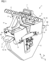
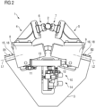
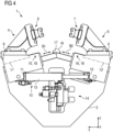
- the Figures 1 - 4 each show schematic representations of a bezel 1 according to an exemplary embodiment.
- the bezel 1 is in the 1 , 2 shown in an operating position, wherein 1 a perspective view of the bezel 1 and 2 shows a front view of the bezel 1, and in FIGS 3 , 4 shown in a non-operative position, wherein 3 a perspective view of the bezel 1 and 4 a front view of the bezel 1 shows.
- the steady rest 1 is used to support or mount a particularly elongate workpiece 2 to be machined, ie in particular by cutting (cf. 1 , 2 ).
- the workpiece 2 can be, as in 1 , 2 shown to act, for example, a wave.
- the steady rest 1 comprises a steady rest body 3 that can be arranged in a device (not shown) for the mechanical, in particular cutting, processing of a workpiece 2 to be mechanically machined mechanical machining of a workpiece 2 to be mechanically machined, d. H. e.g. B. a turning or milling center, can be arranged; for this purpose, the steady rest body 3 is received in a receiving area provided for this purpose, typically the machine bed, of a corresponding device.
- the steady rest base body 3 can be accommodated directly or indirectly with the interposition of a steady rest carrier (not shown) in a receiving area of a corresponding device provided for this purpose.
- the accommodation of the steady rest base body 3 in the device-side receiving area provided for this purpose can include an interaction of suitable, in particular mechanical, interfaces on the steady rest base body side or steady rest carrier side and the receiving area side.
- the mounting of the steady rest base body 3 in the device-side receiving area provided for this purpose can also enable a movable mounting of the steady rest base body 3 or the steady rest 1 (each possibly together with steady rest carrier) relative to the device.
- the supporting devices 4, 5 each comprise a supporting element 6, 7 supporting the workpiece 2 to be supported.
- the supporting devices 4, 5 are clamping or tensioning devices, i. H. e.g. B. to clamping or clamping jaw devices, in the case of the support elements 6, 7 is in the embodiment according to clamping or clamping elements, d. H. e.g. B. to clamping or clamping jaws.
- the supporting devices 4, 5 can be moved in a degree of freedom of movement defining a movement path B1, B2, i. H. displaceable in the exemplary embodiment shown in the figures, mounted relative to the bezel base body 3 and arranged or formed on the bezel base body 3 .
- the support device 4 on the left in the figures is movably mounted along the path of movement indicated by the double arrow B1
- the support device 5 on the right in the figures is movably mounted along the path of movement indicated by the double arrow B2.
- the steady rest 1 is therefore distinguished by a movably mounted arrangement or design of its support devices 4 , 5 on the steady rest base body 3 .
- both support devices 4, 5 are mounted on the base body 3 so that they can move relative to the base body 3, it is in principle also conceivable for only one support device 4, 5 to be mounted on the base body movably relative to the base body 3
- Bezel base body 3 is arranged or formed.
- the degree of freedom of movement is in the embodiment shown in the figures in each case a translatory, in particular linear, degree of freedom of movement.
- the movement path B1, B2 defined by the respective degree of freedom of movement is therefore a translatory, in particular linear, movement path in the exemplary embodiment shown in the figures.
- the supporting devices 4, 5 between at least two defined positions or settings, namely one in the 1 , 2 Operating position shown, in which a support of the workpiece 2 to be supported by means of the support devices 4, 5 is possible, and in the 3 , 4 shown non-operating position, in which a support of the supported workpiece 2 by means of the support devices 4, 5 is not possible, are movably mounted.
- the movement paths B1, B2, along which the support devices 4, 5 are movably mounted thus extend between the two defined positions.
- the supporting devices 4, 5 are moved against the workpiece 2 to be supported, in particular clamped or braced against the workpiece 2 to be supported, i.e.
- the supporting devices 4, 5 can be arranged on the steady rest body 3 so that they can move relative to the steady rest body 3 in a manner dependent or independent of one another in each case in a respective movement path B1, B2.
- Dependent movable mounting of the support devices 4, 5 shown means that a change in the position of the first support device 4, 5 caused by a movement of a first support device 4, 5 (mandatory) with a movement of a second support device 4, 5 and thus a change in position a second supporting device 4, 5 is accompanied.
- the movements of the support devices 4, 5 are typically directed unequally, ie the support devices 4, 5 are moved towards or away from each other.
- the dependent movable storage of the support devices 4, 5 is by a movement coupling of the support devices 4, 5, which synchronous or synchronized movements of the support devices 4, 5 z. B. from respective operating in respective non-operating positions and vice versa, allows realized; the supporting devices 4, 5 are therefore coupled in terms of movement.
- the movement coupling of the supporting devices 4, 5 is implemented via a coupling device 10 arranged connected between the supporting devices 4, 5.
- the coupling device 10 is connected via a first coupling section or a first coupling means 11, e.g. B. in the form of a bolt, with a first support device 4 and a second coupling portion or a second coupling means 12, z. B. in the form of a bolt, with a second support device 5 is coupled.
- the coupling device 10 comprises at least one coupling element 13 in the form of a z. B. hydraulic, actuating cylinder.
- the coupling element 13 is coupled to the first supporting device 4 via a first coupling element section or the first coupling means 11 and to the second supporting device 5 via a second coupling element section or the second coupling means 12 .
- the coupling device 10 can therefore be an actuating cylinder device.
- the coupling device 10 can be a component of a drive device 14, which is used to generate a drive force that sets the support devices 4, 5 into motion in a respective degree of freedom of movement is furnished, form.
- the steady rest 1 thus comprises a drive device 14 which is set up to generate a drive force which sets the support devices 4, 5 into motion in a respective degree of freedom of movement.
- the drive device 14 is indirect, i. H. with the interposition of a force-transmitting assembly, d. H. the coupling device 10, coupled to the supporting devices 4, 5 to be set in motion.
- the drive device 14 acts on the coupling device 10 in order to cause the coupling element 13 to extend or retract, which, due to the coupling of the coupling element 13 to the supporting devices 4, 5, leads to a movement of the supporting devices 4, 5 relative to the steady rest base body 3.
- the drive device 14 can, for. B. electrically, hydraulically, or mechanically.
- the drive device 14 is designed as an electric or hydraulic drive device, i. H. designed as an electrohydraulic actuator device.
- the main body 3 of the steady rest can be seen to include two ramp-like guide sections 15, 16 which run in a straight line (with a constant gradient with respect to a, e.g. horizontal, reference plane) and are aligned at an angle relative to one another.
- the guide sections 15, 16 are opposite one another (in a front view of the steady rest). arranged or formed horizontally, resulting in a V-like or -shaped arrangement of the guide sections 15, 16; the guide sections 15, 16 form the legs of the V, which merge into a ridge 17 (cut edge) formed by their respective ends.
- the angle ⁇ between the exposed surfaces or sides of the guide sections 15, 16 is therefore greater than 180°.
- the support devices 4 , 5 are mounted movably in the respective degree of freedom of movement relative to a respective guide section 15 , 16 on a guide section 15 , 16 .
- a first Support device 4 is movably mounted relative to a first guide section 15 , ie assigned to the first guide section 15
- a second support device 5 is movably mounted relative to a second guide section 16 , ie assigned to the second guide section 16 .
- the support devices 4, 5 sit directly on the respective guide sections 15, 16.
- the guide sections 15, 16 are each elongate and thus have a longitudinal axis L1, L2.
- a respectively assigned support device 4, 5 is correspondingly mounted in a movement path B1, B2 extending parallel along the longitudinal axis L1, L2 of the respective guide section 15, 16 so as to be movable relative to the respective guide section 15, 16 on the latter.
- the longitudinal axis L1, L2 of a respective guide section 15, 16 thus equally defines the movement path B1, B2, along which a respective support device 4, 5 is arranged or formed so as to be movable relative to the guide section 15, 16.
- the guide sections 15, 16 form part of a guide device which is set up to guide a movement of the support devices 4, 5 in the respective movement path B1, B2.
- the guide sections 15, 16 interact with guide elements 19 that are arranged or formed on the side of the support device.
- the guide device thus comprises first guide elements 18 arranged or formed on the steady rest base body or guide section side and second guide elements 19 arranged or formed on the supporting device side that interact with them.
- the first guide elements 18 arranged or formed on the steady rest base body are a guide surface or geometry with a T-shaped cross section in the exemplary embodiment shown in FIG
- the second guide element 19 is a counter-guide surface or geometry that extends over or around a corresponding guide surface or geometry.
- an inverted configuration of respective first and second guide elements 18, 19 is conceivable.
- the guide device also ensures that the support device 4, 5 cannot be lost on the steady rest base body 3; consequently, the guiding device, in addition to the guiding function, also performs a securing function of the respective support devices 4 , 5 on the steady rest base body 3 .
- a passage possibility is created for a machining tool of a device for mechanical machining of the workpiece 2 to be mechanically machined, so that a machining tool, e.g. a milling tool, in particular along the longitudinal axis of the workpiece to be machined, which is supported by the steady rest 1 2 can pass the bezel 3 via the passage possibility in the direction of the longitudinal axis of the workpiece 2 .
- the steady rest 1 is therefore designed in such a way that it does not prevent continuous mechanical machining of the supported workpiece 2 since a machining tool can pass over the steady rest 1 without interrupting a mechanical machining process.
- FIG 5 , 6 each show a schematic representation of a bezel 1 according to a further embodiment in an operating position, wherein figure 5 a perspective view of the bezel 1 and 6 a front view of the bezel 1 shows.
- the exemplary embodiment shown includes the steady rest 1 here, in addition, a fundamentally optional chip protection device 20, which is set up to prevent the deposit of material removed during the machining, in particular machining, of the workpiece 2, ie in particular to prevent chips from being deposited on functionally relevant sections of the bezel 1 .
- the chip protection device 20 comprises several, in particular plate-like or plate-shaped, chip protection elements 21, 22.
- First chip protection elements 21 can, for. B. in the region of the guide sections 15, 16 may be arranged or formed in order to prevent a deposit of material removed here, second chip protection elements 22 z. B. in the area of the support devices 4, 5 can be arranged or formed in order to prevent a deposit of ablated material here.
- the stripping devices 23 are also supporting device-side stripping devices 23, z. B. in the form of bristles or brushes, which, in particular by appropriate movement of the support devices 4, 5, a stripping or removal of possibly deposited on the guide sections 15, 16 ablation material from the guide sections 15, 16 allow.
- the stripping devices 23 are arranged or formed, for example, in the region of respective second guide elements 19 arranged or formed on the supporting device side.
- the steady rest 1 can have a blocking device (not shown) which is used for blocking a movement of at least one supporting device 4, 5, in particular for blocking a moving into an operating or non-operating position support device 4, 5 in the operating or non-operating position, comprise.
- the locking device can, for. B. act magnetically and / or mechanically; consequently, the locking device can at least one z. B. magnetically and / or mechanically acting blocking element, d. H. e.g. B. include a locking magnet or a locking pin.
Landscapes
- Engineering & Computer Science (AREA)
- Mechanical Engineering (AREA)
- Machine Tool Units (AREA)
- Constituent Portions Of Griding Lathes, Driving, Sensing And Control (AREA)
Priority Applications (1)
| Application Number | Priority Date | Filing Date | Title |
|---|---|---|---|
| EP22201587.7A EP4159364A3 (fr) | 2017-09-15 | 2017-09-15 | Lunette de support d'une pièce à usiner mécaniquement |
Applications Claiming Priority (2)
| Application Number | Priority Date | Filing Date | Title |
|---|---|---|---|
| EP22201587.7A EP4159364A3 (fr) | 2017-09-15 | 2017-09-15 | Lunette de support d'une pièce à usiner mécaniquement |
| EP17191292.6A EP3456464B1 (fr) | 2017-09-15 | 2017-09-15 | Dispositif avec lunette de support |
Related Parent Applications (1)
| Application Number | Title | Priority Date | Filing Date |
|---|---|---|---|
| EP17191292.6A Division EP3456464B1 (fr) | 2017-09-15 | 2017-09-15 | Dispositif avec lunette de support |
Publications (2)
| Publication Number | Publication Date |
|---|---|
| EP4159364A2 true EP4159364A2 (fr) | 2023-04-05 |
| EP4159364A3 EP4159364A3 (fr) | 2023-06-14 |
Family
ID=59895160
Family Applications (2)
| Application Number | Title | Priority Date | Filing Date |
|---|---|---|---|
| EP22201587.7A Pending EP4159364A3 (fr) | 2017-09-15 | 2017-09-15 | Lunette de support d'une pièce à usiner mécaniquement |
| EP17191292.6A Active EP3456464B1 (fr) | 2017-09-15 | 2017-09-15 | Dispositif avec lunette de support |
Family Applications After (1)
| Application Number | Title | Priority Date | Filing Date |
|---|---|---|---|
| EP17191292.6A Active EP3456464B1 (fr) | 2017-09-15 | 2017-09-15 | Dispositif avec lunette de support |
Country Status (6)
| Country | Link |
|---|---|
| US (2) | US12365058B2 (fr) |
| EP (2) | EP4159364A3 (fr) |
| CN (2) | CN121223125A (fr) |
| ES (1) | ES2929713T3 (fr) |
| PL (1) | PL3456464T3 (fr) |
| WO (1) | WO2019052856A1 (fr) |
Families Citing this family (1)
| Publication number | Priority date | Publication date | Assignee | Title |
|---|---|---|---|---|
| IT201900014925A1 (it) * | 2019-08-22 | 2021-02-22 | Danieli Off Mecc | Dispositivo di guida per la guida di una barra di spinta di un mandrino o per la guida di un mandrino in un processo di laminazione di corpi tubolari |
Family Cites Families (26)
| Publication number | Priority date | Publication date | Assignee | Title |
|---|---|---|---|---|
| DE1402955A1 (de) | 1960-11-24 | 1968-10-31 | Hegenscheidt Kg Wilhelm | Unterflur-Profildrehmaschine fuer die Bearbeitung der Umrisse nicht ausgebundener Radsaetze |
| DE2141701A1 (de) * | 1971-08-20 | 1973-03-01 | Bruno Dietl | Stuetzvorrichtung zur halterung von schweren werkstuecken auf werkzeugmaschinen |
| DE2542959A1 (de) * | 1975-09-26 | 1977-03-31 | Eugen Maier | Einrichtung zum aufspannen und/oder zur halterung eines werkstueckes auf arbeitsmaschinen |
| JPS5272992A (en) * | 1975-12-13 | 1977-06-18 | Nippon Steel Corp | Automatically adjustable rest for roll grinding |
| DE3544961A1 (de) * | 1985-12-19 | 1987-07-02 | Smw Spanneinrichtungen | Selbstzentrierende luenette |
| DE4238613A1 (de) * | 1992-11-16 | 1994-05-19 | Smw Schneider & Weishaupt Gmbh | Selbstzentrierende Lünette |
| IT240522Y1 (it) * | 1996-03-19 | 2001-04-02 | Morari Giuseppe E Marilena S N | Lunetta autocentrante con bracci di presa retrattili |
| DE19950706C2 (de) * | 1999-10-21 | 2002-10-02 | Smw Autoblok Spannsysteme Gmbh | Aufspanneinrichtung |
| DE20012710U1 (de) * | 2000-07-22 | 2000-11-23 | Röhm GmbH, 89567 Sontheim | Lünette |
| DE10315006B3 (de) * | 2003-04-02 | 2004-08-19 | Wfl Millturn Technologies Gmbh & Co. Kg | Abstützvorrichtung |
| CN2734403Y (zh) * | 2004-10-11 | 2005-10-19 | 李维谦 | 伺服中心架 |
| CN2843682Y (zh) * | 2005-12-02 | 2006-12-06 | 天水星火机床有限责任公司 | 定位旋转锁紧机构 |
| CN2843680Y (zh) * | 2005-12-02 | 2006-12-06 | 天水星火机床有限责任公司 | 卧式车床c形中心架 |
| CN2925701Y (zh) * | 2006-05-31 | 2007-07-25 | 应圣平 | 一种气动中心架 |
| CN101628381B (zh) * | 2009-07-20 | 2011-06-22 | 徐州工业职业技术学院 | 自动定心、滚动支撑中心架 |
| CN201559993U (zh) * | 2009-10-29 | 2010-08-25 | 天津钢铁集团有限公司 | 用于胶带输送机上的空段式清扫器 |
| CN201604005U (zh) * | 2009-12-03 | 2010-10-13 | 安东石油技术(集团)有限公司 | 一种套管加工中心架的微调装置 |
| CN202015950U (zh) * | 2011-02-08 | 2011-10-26 | 齐齐哈尔齐一机工业产品有限公司 | 一种机床静压中心架 |
| MX2015001303A (es) * | 2012-07-31 | 2015-04-08 | Sms Meer Gmbh | Maquina para el procesamiento de extremos de tubos con un dispositivo centrador para centrar una pieza de trabajo tubular en relacion a un eje de giro. |
| CN102975090B (zh) * | 2012-12-14 | 2015-11-18 | 贵阳险峰机床有限责任公司 | 一种支撑滚柱浮起式的静压中心架 |
| TWI500472B (zh) * | 2013-07-16 | 2015-09-21 | Ind Tech Res Inst | 自動定心之中心架裝置 |
| US9174317B1 (en) * | 2014-08-14 | 2015-11-03 | Arobotech Systems, Inc. | Adjustable fixture mechanism |
| CN104526453B (zh) * | 2015-01-02 | 2016-09-14 | 巨轮智能装备股份有限公司 | 机床工作台防尘装置 |
| DE102015115205A1 (de) * | 2015-09-10 | 2017-03-16 | Walter Maschinenbau Gmbh | Betätigungsvorrichtung für eine Lünette |
| CN105710662A (zh) * | 2016-04-21 | 2016-06-29 | 湖南科技大学 | 一种用于细长轴精密加工的电动中心架 |
| CN107363571A (zh) * | 2017-07-06 | 2017-11-21 | 南通德鑫数控机床有限公司 | 一种凸轮轴数控仿形铣床中心架机构 |
-
2017
- 2017-09-15 PL PL17191292.6T patent/PL3456464T3/pl unknown
- 2017-09-15 EP EP22201587.7A patent/EP4159364A3/fr active Pending
- 2017-09-15 EP EP17191292.6A patent/EP3456464B1/fr active Active
- 2017-09-15 ES ES17191292T patent/ES2929713T3/es active Active
-
2018
- 2018-09-04 CN CN202511748663.6A patent/CN121223125A/zh active Pending
- 2018-09-04 US US16/646,726 patent/US12365058B2/en active Active
- 2018-09-04 WO PCT/EP2018/073733 patent/WO2019052856A1/fr not_active Ceased
- 2018-09-04 CN CN201880073341.8A patent/CN111344108A/zh active Pending
-
2025
- 2025-06-18 US US19/242,018 patent/US20250312875A1/en active Pending
Also Published As
| Publication number | Publication date |
|---|---|
| CN121223125A (zh) | 2025-12-30 |
| WO2019052856A1 (fr) | 2019-03-21 |
| EP3456464A1 (fr) | 2019-03-20 |
| US20250312875A1 (en) | 2025-10-09 |
| US20210031316A1 (en) | 2021-02-04 |
| ES2929713T3 (es) | 2022-12-01 |
| PL3456464T3 (pl) | 2023-01-16 |
| CN111344108A (zh) | 2020-06-26 |
| EP3456464B1 (fr) | 2022-10-19 |
| EP4159364A3 (fr) | 2023-06-14 |
| US12365058B2 (en) | 2025-07-22 |
Similar Documents
| Publication | Publication Date | Title |
|---|---|---|
| EP3197639B1 (fr) | Dispositif d'usinage | |
| EP2566644B1 (fr) | Mandrin centré | |
| EP2874804B1 (fr) | Mécanisme à came | |
| DE8816776U1 (de) | Mehrfach-Spannvorrichtung | |
| DE102019116262A1 (de) | Spannvorrichtung und Werkstückhaltevorrichtung mit einer Spannvorrichtung | |
| EP3294498B1 (fr) | Procédé et dispositif d'usinage destinés à serrer et usiner un composant d'une armoire de distribution | |
| DE873817T1 (de) | Werkzeugmaschine zum Bearbeiten von langen Werkstücken | |
| EP0254741B1 (fr) | Dispositif de retenue et de manipulation d'un objet plat | |
| AT523568A1 (de) | Biegemaschine | |
| EP1990160A2 (fr) | Foreuse avec alimentation en continu | |
| DE29716104U1 (de) | Spannvorrichtung, insbesondere Maschinenschraubstock | |
| DE102015104058B3 (de) | Zentrische Spannvorrichtung | |
| AT517227B1 (de) | Fertigungsanlage zur Fertigung von Werkstücken aus Blech sowie Verfahren dazu | |
| EP3456464B1 (fr) | Dispositif avec lunette de support | |
| EP3475040B1 (fr) | Machine avec des zones de travail et méthode associée | |
| AT517347B1 (de) | Verfahren zum Betreiben einer Biegepresse | |
| EP1868759B1 (fr) | Dispositif pour former des parties saillantes, des dents, des copeaux, des retraits ou similaire dans une plaque support de garniture de frein | |
| EP1334803B1 (fr) | Dispositif de serrage, notamment étau | |
| DE202024000875U1 (de) | Spannbacke | |
| DE102016115176A1 (de) | Verfahren zur Innenbearbeitung eines Bremssattels einer Scheibenbremse | |
| DE202010000935U1 (de) | Vorrichtung zum Bearbeiten von Werkstücken | |
| DE19701394C1 (de) | Haltevorrichtung für mehrseitig zu bearbeitende Werkstücke | |
| EP2998065B1 (fr) | Dispositif de traitement dote d'une table porte-piece | |
| DE102009044497B4 (de) | Spanneinrichtungssystem | |
| EP2397252B1 (fr) | Machine de traitement |
Legal Events
| Date | Code | Title | Description |
|---|---|---|---|
| PUAI | Public reference made under article 153(3) epc to a published international application that has entered the european phase |
Free format text: ORIGINAL CODE: 0009012 |
|
| STAA | Information on the status of an ep patent application or granted ep patent |
Free format text: STATUS: THE APPLICATION HAS BEEN PUBLISHED |
|
| AC | Divisional application: reference to earlier application |
Ref document number: 3456464 Country of ref document: EP Kind code of ref document: P |
|
| AK | Designated contracting states |
Kind code of ref document: A2 Designated state(s): AL AT BE BG CH CY CZ DE DK EE ES FI FR GB GR HR HU IE IS IT LI LT LU LV MC MK MT NL NO PL PT RO RS SE SI SK SM TR |
|
| PUAL | Search report despatched |
Free format text: ORIGINAL CODE: 0009013 |
|
| AK | Designated contracting states |
Kind code of ref document: A3 Designated state(s): AL AT BE BG CH CY CZ DE DK EE ES FI FR GB GR HR HU IE IS IT LI LT LU LV MC MK MT NL NO PL PT RO RS SE SI SK SM TR |
|
| RIC1 | Information provided on ipc code assigned before grant |
Ipc: B23Q 1/58 20060101ALN20230508BHEP Ipc: B23Q 1/76 20060101AFI20230508BHEP |
|
| P01 | Opt-out of the competence of the unified patent court (upc) registered |
Effective date: 20230525 |
|
| STAA | Information on the status of an ep patent application or granted ep patent |
Free format text: STATUS: REQUEST FOR EXAMINATION WAS MADE |
|
| 17P | Request for examination filed |
Effective date: 20231212 |
|
| RBV | Designated contracting states (corrected) |
Designated state(s): AL AT BE BG CH CY CZ DE DK EE ES FI FR GB GR HR HU IE IS IT LI LT LU LV MC MK MT NL NO PL PT RO RS SE SI SK SM TR |
|
| STAA | Information on the status of an ep patent application or granted ep patent |
Free format text: STATUS: EXAMINATION IS IN PROGRESS |
|
| 17Q | First examination report despatched |
Effective date: 20260105 |