EP4159367B1 - Machine-outil et système de commande de machine-outil - Google Patents
Machine-outil et système de commande de machine-outil Download PDFInfo
- Publication number
- EP4159367B1 EP4159367B1 EP21811825.5A EP21811825A EP4159367B1 EP 4159367 B1 EP4159367 B1 EP 4159367B1 EP 21811825 A EP21811825 A EP 21811825A EP 4159367 B1 EP4159367 B1 EP 4159367B1
- Authority
- EP
- European Patent Office
- Prior art keywords
- state
- coolant
- protection unit
- operator
- unit
- Prior art date
- Legal status (The legal status is an assumption and is not a legal conclusion. Google has not performed a legal analysis and makes no representation as to the accuracy of the status listed.)
- Active
Links
Images


Classifications
-
- B—PERFORMING OPERATIONS; TRANSPORTING
- B23—MACHINE TOOLS; METAL-WORKING NOT OTHERWISE PROVIDED FOR
- B23Q—DETAILS, COMPONENTS, OR ACCESSORIES FOR MACHINE TOOLS, e.g. ARRANGEMENTS FOR COPYING OR CONTROLLING; MACHINE TOOLS IN GENERAL CHARACTERISED BY THE CONSTRUCTION OF PARTICULAR DETAILS OR COMPONENTS; COMBINATIONS OR ASSOCIATIONS OF METAL-WORKING MACHINES, NOT DIRECTED TO A PARTICULAR RESULT
- B23Q11/00—Accessories fitted to machine tools for keeping tools or parts of the machine in good working condition or for cooling work; Safety devices specially combined with or arranged in, or specially adapted for use in connection with, machine tools
- B23Q11/08—Protective coverings for parts of machine tools; Splash guards
- B23Q11/0891—Protective coverings for parts of machine tools; Splash guards arranged between the working area and the operator
-
- B—PERFORMING OPERATIONS; TRANSPORTING
- B23—MACHINE TOOLS; METAL-WORKING NOT OTHERWISE PROVIDED FOR
- B23Q—DETAILS, COMPONENTS, OR ACCESSORIES FOR MACHINE TOOLS, e.g. ARRANGEMENTS FOR COPYING OR CONTROLLING; MACHINE TOOLS IN GENERAL CHARACTERISED BY THE CONSTRUCTION OF PARTICULAR DETAILS OR COMPONENTS; COMBINATIONS OR ASSOCIATIONS OF METAL-WORKING MACHINES, NOT DIRECTED TO A PARTICULAR RESULT
- B23Q11/00—Accessories fitted to machine tools for keeping tools or parts of the machine in good working condition or for cooling work; Safety devices specially combined with or arranged in, or specially adapted for use in connection with, machine tools
- B23Q11/0078—Safety devices protecting the operator, e.g. against accident or noise
-
- B—PERFORMING OPERATIONS; TRANSPORTING
- B23—MACHINE TOOLS; METAL-WORKING NOT OTHERWISE PROVIDED FOR
- B23Q—DETAILS, COMPONENTS, OR ACCESSORIES FOR MACHINE TOOLS, e.g. ARRANGEMENTS FOR COPYING OR CONTROLLING; MACHINE TOOLS IN GENERAL CHARACTERISED BY THE CONSTRUCTION OF PARTICULAR DETAILS OR COMPONENTS; COMBINATIONS OR ASSOCIATIONS OF METAL-WORKING MACHINES, NOT DIRECTED TO A PARTICULAR RESULT
- B23Q11/00—Accessories fitted to machine tools for keeping tools or parts of the machine in good working condition or for cooling work; Safety devices specially combined with or arranged in, or specially adapted for use in connection with, machine tools
- B23Q11/08—Protective coverings for parts of machine tools; Splash guards
-
- B—PERFORMING OPERATIONS; TRANSPORTING
- B23—MACHINE TOOLS; METAL-WORKING NOT OTHERWISE PROVIDED FOR
- B23Q—DETAILS, COMPONENTS, OR ACCESSORIES FOR MACHINE TOOLS, e.g. ARRANGEMENTS FOR COPYING OR CONTROLLING; MACHINE TOOLS IN GENERAL CHARACTERISED BY THE CONSTRUCTION OF PARTICULAR DETAILS OR COMPONENTS; COMBINATIONS OR ASSOCIATIONS OF METAL-WORKING MACHINES, NOT DIRECTED TO A PARTICULAR RESULT
- B23Q11/00—Accessories fitted to machine tools for keeping tools or parts of the machine in good working condition or for cooling work; Safety devices specially combined with or arranged in, or specially adapted for use in connection with, machine tools
- B23Q11/10—Arrangements for cooling or lubricating tools or work
-
- Y—GENERAL TAGGING OF NEW TECHNOLOGICAL DEVELOPMENTS; GENERAL TAGGING OF CROSS-SECTIONAL TECHNOLOGIES SPANNING OVER SEVERAL SECTIONS OF THE IPC; TECHNICAL SUBJECTS COVERED BY FORMER USPC CROSS-REFERENCE ART COLLECTIONS [XRACs] AND DIGESTS
- Y02—TECHNOLOGIES OR APPLICATIONS FOR MITIGATION OR ADAPTATION AGAINST CLIMATE CHANGE
- Y02P—CLIMATE CHANGE MITIGATION TECHNOLOGIES IN THE PRODUCTION OR PROCESSING OF GOODS
- Y02P70/00—Climate change mitigation technologies in the production process for final industrial or consumer products
- Y02P70/10—Greenhouse gas [GHG] capture, material saving, heat recovery or other energy efficient measures, e.g. motor control, characterised by manufacturing processes, e.g. for rolling metal or metal working
Definitions
- the present disclosure relates to a machine tool and a machine tool control system.
- a machine tool has the function of cooling a cutting tool with a coolant (a cutting fluid).
- a machining processing unit included in the machine tool is enclosed by a cover so as to prevent shavings generated as a result of a workpiece being processed from being scattered into the surrounding environment.
- a window portion is provided for an operator to visually check the progress of the processing operation.
- the coolant and the shavings are scattered to the window portion, which obstructs the visibility of the operator via the window portion.
- Patent Literature 1 proposes a system that includes a machine tool window and an apparatus for clearing droplets of a cutting fluid from the machine tool window, wherein the apparatus includes: one or more transducers attached to the window, each being operable to generate ultrasonic waves in the window; and a generator for providing ultrasonic driving signals to the one or more transducers, and wherein during operation of the system, the droplets of the cutting fluid are ultrasonically cleared from the window.
- KR 101 939 201 B1 discloses a machine tool according to the preamble of claims 1 to 3.
- a machine tool according to the invention is defined in the independent claims 1-3.
- Another aspect of the present disclosure relates to a machine tool control system including: a plurality of machine tools, each being the machine tool described above; and an image capturing apparatus for monitoring the plurality of machine tools, wherein the sensor detects the operator by using the image capturing apparatus.
- the cover encloses a processing space in which a workpiece is processed, and has a window portion for visual inspection of the processing space from outside.
- the cover is also called a splash guard, and functions to cause shavings and a coolant to be confined within the processing space, the shavings being generated as a result of a workpiece being processed in the processing space.
- the cover includes a side wall and a ceiling wall that enclose the processing space.
- the cover may include a door that moves relative to the cover. For example, the door switches an opening formed in the cover between an open state and a closed state by being slid along the opening. In the open state, an operator can access the processing space, and in the closed state, the processing of a workpiece is performed.
- the window portion may be provided in the door of the cover.
- the machining processing unit is a component essential for the machine tool provided in the processing space.
- the machining processing unit includes, for example, a worktable for fixing a workpiece, a spindle that is attached to a column, and a cutting tool (bite) that is fixed to the spindle.
- the machining processing unit may include a spindle table for fixing a workpiece and a tool rest for fixing a cutting tool for processing the workpiece.
- the operation panel is an apparatus for inputting instructions to the machining processing unit, and is provided outside of the cover.
- the operation panel includes a CPU board, a main storage device, an auxiliary storage device, and the like.
- the operation panel is provided, for example, in the vicinity of the opening of the cover or the door.
- the operation panel may be configured to perform overall control on the machine tool that includes the machining processing unit.
- the cooling system is a system for cooling the workpiece and the cutting tool, and includes a coolant supply unit for supplying a coolant into the processing space, a coolant protection unit that operates to limit adhesion of the coolant to the window portion, and a control unit (hereinafter referred to as a "visibility control unit") that switches the state of the coolant protection unit based on the result of detection performed by a sensor (hereinafter referred to as an "operator sensor”) for detecting an operator present around the cover.
- the operator sensor may be included in the machine tool, or may be disposed outside of the machine tool.
- the coolant supply unit includes a nozzle for spraying a large amount of a liquid coolant toward the workpiece and the cutting tool.
- the coolant that has been sprayed to the workpiece and the cutting tool is recovered by a predetermined recovery unit, and separated from the shavings so as to be reused.
- the following configurations are also possible: a configuration in which the coolant is sprayed from a tool tip end after passing through the spindle; a configuration in which the coolant is sprayed from the ceiling to wash away the shavings in the processing space; and the like.
- the coolant protection unit is not particularly limited as long as it is possible to operate to limit adhesion of the coolant to the window portion.
- Examples of the coolant protection unit include: an air spray apparatus for spraying air toward the window portion; a rotary window (clear view screen) for shaking off the coolant adhering to the window portion by the centrifugal force; and the like. Any of these coolant protection units consumes energy, such as power, to perform operations, and it is therefore desired that an operating state and a dormant state are efficiently repeated.
- energy such as power
- the operator sensor may be any sensor as long as it is possible to detect the operator present around the cover, and the configuration of the operator sensor is not particularly limited.
- the waste of energy can be suppressed by the visibility control unit selectively causing the coolant protection unit to operate only when the operator sensor has detected the presence of the operator around the cover.
- the presence of the operator may be detected in a non-contact manner by using, but not limited to, an infrared sensor, an optical sensor, an image recognition camera, or the like.
- an image recognition camera of a superordinate system that manages a plurality of machine tools may be used.
- the visibility control unit may be configured by using, for example, the CPU board, the main storage device, the auxiliary storage device, and the like that are included in the operation panel, or by using a control unit of a superordinate management unit that manages a plurality of machine tools.
- the visibility control unit issues, for example, an instruction to bring the coolant protection unit into a second state when the operator sensor has not detected the operator, and issues an instruction to bring the coolant protection unit into a first state when the operator sensor has detected the operator.
- the first state is a state in which the coolant protection unit operates
- the second state is a dormant state in which the coolant protection unit does not operate, or a state in which the coolant protection unit operates at an output lower than that in the first state.
- the window portion When the coolant protection unit operates at an output lower than that in the first state, the window portion does not become too dirty, and thus the window portion can be rapidly cleaned at a timing when the coolant protection unit is brought into the first state. While the coolant protection unit is operating at the lower output in the second state, the window portion does not need to be cleaned to such a degree that a visual inspection via the window portion can be performed.
- the term "output" refers to power (W). That is, the power of the coolant protection unit in the second state is sufficiently smaller than the power of the coolant protection unit in the first state.
- the first state may be selected from among a plurality of output states.
- the visibility control unit may select one from among the plurality of output states based on the duration of the most recent second state. For example, when the duration of the most recent second state is long, by causing the coolant protection unit to operate in a higher output state, the coolant and the shavings adhering to the window portion during the period in which the coolant protection unit is in the second state can be rapidly removed to instantly clear the visibility. On the other hand, when the duration of the most recent second state is short, the amount of the coolant and the shavings adhering to the window portion during the period in which the coolant protection unit is in the second state is small, and thus the coolant protection unit may be caused to operate at a lower output.
- the number of output states from which the first state can be selected may be two, or may be three or more.
- the first state may be selected from among two states including a normal output state and a high output state in which the output is higher than that in the normal output state.
- any one of a plurality of high output states with different outputs may be selected.
- the visibility control unit may control the coolant protection unit to decrease or increase the output in the first state based on the duration of the first state. For example, at an early stage immediately after the coolant protection unit has been switched from the second state to the first state, the coolant and the shavings adhering to the window portion may be removed in the high output state, and thereafter, the state may be switched to the normal output state. In this case, for example, when the operator performs a visual inspection operation, the operator can soon smoothly have good visibility.
- the visibility control unit automatically switches the output state of the coolant protection unit to a higher output state.
- the visibility control unit may be switchable between a first mode and a second mode.
- the first mode is a mode in which the visibility control unit switches the state of the coolant protection unit based on the result of detection performed by the sensor.
- the second mode is a mode in which the state of the coolant protection unit can be manually switched.
- the operator sensor may detect the operator based on an intended operation of the operator.
- the intended operation may be, for example, an operation performed around the operation panel or the window portion by the operator.
- the operation performed around the operation panel by the operator is typically an operation of the operation panel performed by the operator.
- the operator sensor may detect an operation signal of the operation panel.
- the intended operation of the operator (the operation of the operation panel) may be detected by using, for example, a pressure sensitive sensor or the like when the operator touches the operation panel.
- the operation performed around the window portion by the operator may be a visual inspection operation of visually inspecting the processing space via the window portion performed by the operator.
- the operator sensor may detect the action of the operator approaching the window portion as the visual inspection operation.
- detection may be performed by using an infrared sensor or the like that is provided in the vicinity of the window portion outside of the cover, but the action of the operator approaching the window portion may be detected by using an image capturing apparatus (hereinafter referred to as a "first image capturing apparatus") that is installed in the processing space.
- the first image capturing apparatus for example, one or more image capturing apparatuses may be provided in the processing space for the purposes of monitoring the processing state of the workpiece, monitoring the accumulated state of the shavings, measuring the dimensions of the processed workpiece, detecting an abnormal state, and the like.
- the need for providing a dedicated operator sensor for a cooling system can be eliminated.
- the first image capturing apparatus installed in the processing space is not sensitive to most of the operations performed by the operator outside of the cover, and detects the visual inspection operation only when the operator has brought his/her face very close to the window portion, and thus a malfunction of the coolant protection unit is suppressed. That is, it is possible to detect the visual inspection operation of visually inspecting the processing space via the window portion performed by the operator with high accuracy while suppressing an increase in cost.
- the present invention encompasses a machine tool control system.
- a superordinate management unit that manages the plurality of machine tools.
- the superordinate management unit directs, for example, preparation of an operation schedule of operations performed in the factory, execution of the operation schedule, and the like.
- the superordinate management unit includes at least one image capturing apparatus (hereinafter referred to as a "second image capturing apparatus") for monitoring the operation status of the plurality of machine tools, and the like.
- the second image capturing apparatus may also function as the operator sensor.
- the second image capturing apparatus detects an intended operation of the operator based on images, and transmits the result of detection to the visibility control unit.
- the visibility control unit may be included in the superordinate management unit, or may be included in each machine tool. In the case where the visibility control unit is included in each machine tool, necessary instructions are transmitted from the superordinate management unit to the visibility control units included in the machine tools.
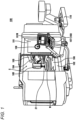
- FIG. 1 is a schematic perspective view showing an overall configuration of a machine tool 100 according to an embodiment of the present invention.
- FIG. 2 is a schematic perspective view of a processing space S in the machine tool 100.
- FIG. 3 is a block diagram showing a schematic configuration of a cooling system 2.
- FIG. 4 is a configuration diagram showing an example of a coolant protection unit.
- the machine tool 100 is installed directly on the floor of a factory or the like.
- the machine tool 100 includes: a cover 101 that encloses the processing space S where a workpiece W is processed and has a window portion 101W for visual inspection of the processing space S from outside; a bed 102 that is disposed in the processing space S enclosed by the cover 101; a column 103 that extends in the Z direction (upward in FIG. 1 ) from the bed 102; a saddle 104 that extends in the X direction (leftward in FIG.
- the bed 102, the column 103, the saddle 104, the spindle head 105, the cutting tool 21, and the table 106 constitute a machining processing unit 1.
- the machine tool 100 can perform perforation processing, polishing processing, or the like on the workpiece W placed on the table 106 by attaching, instead of the cutting tool 21, an appropriate processing tool such as a perforation tool (a drill) or a polishing tool (a grindstone).
- the machine tool 100 may be, for example, a 5-axis multi-processing machine that can process multiple sides of a workpiece W with one chucking by controlling the X axis, the Y axis, the Z axis, the rotation axis, and the tilting axis.
- the machine tool 100 includes: a coolant supply unit 30 for supplying a coolant into the processing space S (see FIG. 2 ); an operation panel 107 for inputting instructions to the machining processing unit 1 that is provided outside of the cover 101; a coolant protection unit 108 that operates to limit adhesion of the coolant to the window portion 101W; a first image capturing apparatus 40, such as a CCD camera, that also functions as an operator sensor for detecting an operator; and a visibility control unit 109 that switches the state of the coolant protection unit 108 based on the result of detection performed by the first image capturing apparatus 40.
- a coolant supply unit 30 for supplying a coolant into the processing space S (see FIG. 2 ); an operation panel 107 for inputting instructions to the machining processing unit 1 that is provided outside of the cover 101; a coolant protection unit 108 that operates to limit adhesion of the coolant to the window portion 101W; a first image capturing apparatus 40, such as a CCD camera, that also functions as an operator sensor for
- the coolant protection unit 108 is configured as a clear view screen that is provided in the window portion 101W of the cover 101, and the clear view screen itself functions as the coolant protection unit 108.
- the first image capturing apparatus 40 also has the function of monitoring the workpiece W being processed, the cutting tool 21, and the background thereof.
- the visibility control unit 109 is configured by using a CPU board, a main storage device, an auxiliary storage device, and the like that are included in the operation panel 107.
- the coolant supply unit 30, the coolant protection unit (clear view screen) 108 that is provided in the window portion 101W, the first image capturing apparatus 40 that also functions as the operator sensor, the visibility control unit 109 that is included in the operation panel 107 constitute a cooling system 2.
- the coolant that has been sprayed to the workpiece W and the cutting tool 21 is recovered by a coolant recovery unit 110, and separated from the shavings so as to be reused.
- the workpiece W is fixed to the table 106 and includes a circular protruding portion T about the Z axis.
- a driving unit 20 for driving the cutting tool 21 to rotate, and a plurality of illumination units 50 for illuminating the workpiece W being processed, such as LEDs, are provided in the processing space S.
- the cutting tool 21 is attached to the spindle head 105 via a driving rod 22 and configured to rotate about a central axis that is parallel to the Z axis.
- the protruding portion T of the workpiece W is shaved to have a desired radius.
- the processing method performed by the machine tool 100 is not intended to limit the scope of the present invention.
- the shape into which the workpiece W is processed is not limited to the simple shape described above, and the present invention is applicable to, for example, various shapes and processes implemented by the 5-axis multi-processing machine.
- the cutting tool 21 is brought into contact with the protruding portion T of the workpiece W while the cutting tool 21 is rotated about the Z axis by a motor (the driving unit 20) that is disposed in the spindle head 105, and at the same time, a large amount of a coolant is sprayed from a nozzle 31 of the coolant supply unit 30 toward the workpiece W and the cutting tool 21 to cool the workpiece W and the cutting tool 21.
- the coolant that has been sprayed from the nozzle 31 collides with the workpiece W and the cutting tool 21 and is scattered and formed into droplets.
- the scattered matter generated while the workpiece is being processed includes, in addition to the droplets of the coolant, a large amount of shavings generated from the workpiece being processed.
- the scattered matter normally adheres to the window portion 101W for visual inspection of the processing space.
- the first image capturing apparatus 40 also functions as an operator sensor for detecting a visual inspection operation of visually inspecting the processing space via the clear view screen provided in the window portion 101W performed by the operator (or in other words, an action of the operator approaching the window portion).
- the result of detection is transmitted to the visibility control unit 109, and the visibility control unit 109 selects the state of the coolant protection unit 108 (clear view screen) based on the result of detection, and switches the state of the coolant protection unit 108 where necessary.
- the coolant protection unit 108 includes: an annular frame 1011; an in-frame window portion 1012 that rotates within the annular frame 1011; a central driving unit (motor) 1013 that is disposed at the center of the in-frame window portion 1012 and causes the in-frame window portion 1012 to rotate; and an air nozzle 1014 for blowing air into a gap between the annular frame 1011 and the in-frame window portion 1012.
- the central driving unit 1013 is supported by a bridge portion 1015 that is connected to the annular frame 1011 and also has the function of fixing the in-frame window portion 1012 to the center of the annular frame 1011.
- the in-frame window portion 1012 is rotated at a high speed to limit the adhesion of the coolant to the in-frame window portion 1012 itself by the centrifugal force.
- the operator can always have clear visibility because the coolant protection unit 108 is rotated at a high speed at a timing when a visual inspection by the operator is needed, while saving the energy for driving the coolant protection unit 108 by configuring the visibility control unit 109 to switch the state of the coolant protection unit 108.
- FIG. 5 is a block diagram showing a schematic configuration of a machine tool control system 3 for controlling a plurality of machine tools.
- the control system 3 includes a plurality of machine tools A to C (100A, 100B, and 100C (hereinafter, N will be used when it is necessary to collectively refer to A, B, and C) and a superordinate management unit 200 that manages the plurality of machine tools 100N.
- the superordinate management unit 200 includes a second image capturing apparatus 240 for monitoring the state of the plurality of machine tools 100N.
- the second image capturing apparatus 240 can also function as the operator sensor, and the second image capturing apparatus 240 detects an intended operation of the operator.
- the superordinate management unit 200 includes visibility control units 109A, 109B, and 109C (109N) for the plurality of machine tools 100N, and constitutes a portion of a cooling system 2N for cooling the plurality of machine tools 100N.
- the visibility control units 109N control coolant protection units 108A, 108B, and 108C (108N) of the corresponding machine tools based on the results of detection. The same control as that performed by the cooling system 2 of the machine tool is performed.
- the number of machine tools included in the control system 3 is not particularly limited. Also, the number of second image capturing apparatuses 240 is not limited to one, and may be more.
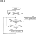
- FIG. 6 is a flow diagram showing an example (a first aspect) of controlling the coolant protection unit 108.
- the visibility control unit 109 is switchable between a first mode and a second mode.
- the visibility control unit 109 automatically switches the state of the coolant protection unit 108 between a first state and a second state based on the result of detection performed by an operator sensor (the first image capturing apparatus 40 or the second image capturing apparatus 240).
- the operator can manually switch the state of the coolant protection unit 108, and the visibility control unit 109 does not automatically operate.
- the first state is a state in which the coolant protection unit 108 operates
- the second state is a dormant state in which the coolant protection unit 108 does not operate or an idle state in which the coolant protection unit 108 operates at an output sufficiently lower than that in the first state.
- the visibility control unit 109 determines whether or not the visibility control unit 109 is in the first mode (ST01). If it is determined that the visibility control unit 109 is not in the first mode (N), the visibility control unit 109 is in the second mode, and thus the control ends here. On the other hand, if it is determined that the visibility control unit 109 is in the first mode (Y), the visibility control unit 109 determines whether or not the operator sensor has detected a visual inspection operation of the operator (ST02). If it is determined that the operator sensor has not detected a visual inspection operation of the operator (N), the visibility control unit 109 selects the second state to keep the coolant protection unit 108 in the dormant state or the idle state (ST03).
- the visibility control unit 109 determines whether the coolant protection unit 108 is in the first state at this time (ST04). If it is determined that the coolant protection unit 108 is already operating in the first state (Y), the flow returns to ST02, and the same control is repeated. On the other hand, if it is determined that the coolant protection unit 108 is not in the first state (N), the coolant protection unit 108 is in the second state at this time, and thus the visibility control unit 109 switches the state of the coolant protection unit 108 to the first state to cause the coolant protection unit 108 to operate (ST05). After that, the flow returns to ST02, and the same control is repeated.
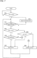
- FIG. 7 is a flow diagram showing another example (a second aspect) of controlling the coolant protection unit 108.
- a first output normal output
- a second output high output
- the output in the first state by determining whether or not duration t1 of the first state is shorter than predetermined length of time T1 or by determining whether or not duration t2 of the most recent second state is shorter than predetermined length of time T2.
- the processing operations from ST01 to ST04 are the same as those of the first aspect. If it is determined in ST04 that the coolant protection unit 108 is in the first state (Y), the visibility control unit 109 determines whether or not duration t1 of the first state is greater than or equal to predetermined length of time T1 (or in other words, whether t1 ⁇ T1 is established) (ST05). If it is determined that t1 ⁇ T1 is not established (t1 ⁇ T1 is established) (N), from which it is estimated that the visual inspection operation is smoothly performed by the operator in a short period of time, and thus the visibility control unit 109 causes the coolant protection unit 108 to operate at a normal output (ST06). After that, the flow returns to ST02, and the same control is repeated.
- the visibility control unit 109 causes the coolant protection unit 108 to operate at a high output (ST07). After that, the flow returns to ST02, and the same control is performed.
- the visibility control unit 109 is in the second state. In this case, whether or not duration t2 of the most recent second state is shorter than predetermined length of time T2 (or in other words, t2 ⁇ T2 is established) is determined (ST08). If it is determined that t2 ⁇ T2 is established (Y), from which it is estimated that the window portion is less dirty, and thus the visibility control unit 109 causes the coolant protection unit 108 to operate at a normal output (ST06). After that, the flow returns to ST02, and the same control is repeated.
- the visibility control unit 109 causes the coolant protection unit 108 to operate at a normal output (ST06). After that, the flow returns to ST02, and the same control is repeated.
- the present invention is applicable to a machine tool that includes a cooling system, and a machine tool control system for controlling the machine tool.
Landscapes
- Engineering & Computer Science (AREA)
- Mechanical Engineering (AREA)
- Auxiliary Devices For Machine Tools (AREA)
Claims (13)
- Machine-outil comprenant :un protecteur (101) qui entoure un espace de traitement dans lequel une pièce est traitée et qui comporte une partie fenêtre (101W) pour l'inspection visuelle de l'espace de traitement depuis l'extérieur ;une unité de traitement d'usinage placée dans l'espace de traitement ;un panneau de commande (107) pour saisir des instructions pour l'unité de traitement d'usinage, le panneau de commande étant placé à l'extérieur du protecteur ; etun système de refroidissement pour refroidir l'unité de traitement d'usinage,le système de refroidissement comprenant :une unité de distribution de fluide de refroidissement pour distribuer un fluide de refroidissement dans l'espace de traitement ;une unité de refoulement de fluide de refroidissement (108) qui est actionnée pour limiter l'adhésion du fluide de refroidissement à la partie fenêtre ; etune unité de commande qui change un état de l'unité de refoulement de fluide de refroidissement en fonction d'un résultat d'une détection effectuée par un capteur pour détecter la présence d'un opérateur à proximité du protecteur,caractérisée en ce que l'unité de commande met l'unité de refoulement de fluide de refroidissement dans un premier état lorsque le capteur a détecté l'opérateur, et met l'unité de refoulement de fluide de refroidissement dans un second état lorsque le capteur n'a pas détecté l'opérateur,le premier état est un état dans lequel l'unité de refoulement de fluide de refroidissement est actionnée,le second état est un état inactif dans lequel l'unité de refoulement de fluide de refroidissement n'est pas actionnée ou un état dans lequel l'unité de refoulement de fluide de refroidissement est actionnée à un rythme de fonctionnement inférieur à celui du premier état,le premier état est choisi parmi une pluralité d'états correspondant à des rythmes de fonctionnement, etl'unité de commande choisit l'un de la pluralité d'états correspondant à des rythmes de fonctionnement en fonction d'une durée du second état le plus récent.
- Machine-outil comprenant :un protecteur qui entoure un espace de traitement dans lequel une pièce est traitée et qui comporte une partie fenêtre pour l'inspection visuelle de l'espace de traitement depuis l'extérieur ;une unité de traitement d'usinage placée dans l'espace de traitement ;un panneau de commande pour saisir des instructions pour l'unité de traitement d'usinage, le panneau de commande étant placé à l'extérieur du protecteur ; etun système de refroidissement pour refroidir l'unité de traitement d'usinage,le système de refroidissement comprenant :une unité de distribution de fluide de refroidissement pour distribuer un fluide de refroidissement dans l'espace de traitement ;une unité de refoulement de fluide de refroidissement qui est actionnée pour limiter l'adhésion du fluide de refroidissement à la partie fenêtre ; etune unité de commande qui change un état de l'unité de refoulement de fluide de refroidissement en fonction d'un résultat d'une détection effectuée par un capteur pour détecter la présence d'un opérateur à proximité du protecteur,caractérisée en ce que l'unité de commande met l'unité de refoulement de fluide de refroidissement dans un premier état lorsque le capteur a détecté l'opérateur, et met l'unité de refoulement de fluide de refroidissement dans un second état lorsque le capteur n'a pas détecté l'opérateur,le premier état est un état dans lequel l'unité de refoulement de fluide de refroidissement est actionnée,le second état est un état inactif dans lequel l'unité de refoulement de fluide de refroidissement n'est pas actionnée ou un état dans lequel l'unité de refoulement de fluide de refroidissement est actionnée à un rythme de fonctionnement inférieur à celui du premier état, etl'unité de commande diminue ou augmente le rythme de fonctionnement dans le premier état en fonction d'une durée du premier état.
- Machine-outil comprenant :un protecteur qui entoure un espace de traitement dans lequel une pièce est traitée et qui comporte une partie fenêtre pour l'inspection visuelle de l'espace de traitement depuis l'extérieur ;une unité de traitement d'usinage placée dans l'espace de traitement ;un panneau de commande pour saisir des instructions pour l'unité de traitement d'usinage, le panneau de commande étant placé à l'extérieur du protecteur ; etun système de refroidissement pour refroidir l'unité de traitement d'usinage,le système de refroidissement comprenant :une unité de distribution de fluide de refroidissement pour distribuer un fluide de refroidissement dans l'espace de traitement ;une unité de refoulement de fluide de refroidissement qui est actionnée pour limiter l'adhésion du fluide de refroidissement à la partie fenêtre ; etune unité de commande qui change un état de l'unité de refoulement de fluide de refroidissement en fonction d'un résultat d'une détection effectuée par un capteur pour détecter la présence d'un opérateur à proximité du protecteur,caractérisée en ce que l'unité de commande peut être basculée entre un premier mode et un second mode,dans le premier mode, l'unité de commande change l'état de l'unité de refoulement de fluide de refroidissement en fonction du résultat de la détection effectuée par le capteur, etdans le second mode, l'état de l'unité de refoulement de fluide de refroidissement peut être changé manuellement.
- Machine-outil selon la revendication 3,dans laquelle l'unité de commande met l'unité de refoulement de fluide de refroidissement dans un premier état lorsque le capteur a détecté l'opérateur, et met l'unité de refoulement de fluide de refroidissement dans un second état lorsque le capteur n'a pas détecté l'opérateur,le premier état est un état dans lequel l'unité de refoulement de fluide de refroidissement est actionnée, etle second état est un état inactif dans lequel l'unité de refoulement de fluide de refroidissement n'est pas actionnée ou un état dans lequel l'unité de refoulement de fluide de refroidissement est actionnée à un rythme de fonctionnement inférieur à celui du premier état.
- Machine-outil selon la revendication 2 ou 4,dans laquelle le premier état est choisi parmi une pluralité d'états correspondant à des rythmes de fonctionnement, etl'unité de commande choisit l'un de la pluralité d'états correspondant à des rythmes de fonctionnement en fonction d'une durée du second état le plus récent.
- Machine-outil selon la revendication 1 ou 4,
dans laquelle l'unité de commande diminue ou augmente le rythme de fonctionnement dans le premier état en fonction d'une durée du premier état. - Machine-outil selon la revendication 1 ou 2,dans laquelle l'unité de commande peut être basculée entre un premier mode et un second mode,dans le premier mode, l'unité de commande change l'état de l'unité de refoulement de fluide de refroidissement en fonction du résultat de la détection effectuée par le capteur, etdans le second mode, l'état de l'unité de refoulement de fluide de refroidissement peut être changé manuellement.
- Machine-outil selon l'une quelconque des revendications 1 à 7,
dans laquelle le capteur détecte l'opérateur en fonction d'une intention d'action de l'opérateur. - Machine-outil selon la revendication 8,
dans laquelle l'intention d'action correspond à une action exécutée par l'opérateur à proximité du panneau de commande ou de la partie fenêtre. - Machine-outil selon la revendication 8,
dans laquelle l'intention d'action correspond à une action d'inspection visuelle exécutée par l'opérateur consistant à inspecter visuellement l'espace de traitement à travers la partie fenêtre. - Machine-outil selon la revendication 10,
dans laquelle le capteur détecte le fait que l'opérateur s'approche de la partie fenêtre comme une action d'inspection visuelle. - Machine-outil selon la revendication 11,
dans laquelle le capteur détecte le fait que l'opérateur s'approche de la partie fenêtre au moyen d'un premier appareil de capture d'images qui est installé dans l'espace de traitement. - Système de commande de machine-outil comprenant :une pluralité de machines-outils, chacune étant une machine-outil selon l'une quelconque des revendications 1 à 3 ; etun second appareil de capture d'images pour surveiller la pluralité de machines-outils,dans lequel le capteur détecte l'opérateur au moyen du second appareil de capture d'images.
Applications Claiming Priority (2)
| Application Number | Priority Date | Filing Date | Title |
|---|---|---|---|
| JP2020091785A JP6890704B1 (ja) | 2020-05-26 | 2020-05-26 | 工作機械および工作機械の制御システム |
| PCT/JP2021/019865 WO2021241597A1 (fr) | 2020-05-26 | 2021-05-25 | Machine-outil et système de commande de machine-outil |
Publications (3)
| Publication Number | Publication Date |
|---|---|
| EP4159367A1 EP4159367A1 (fr) | 2023-04-05 |
| EP4159367A4 EP4159367A4 (fr) | 2024-07-10 |
| EP4159367B1 true EP4159367B1 (fr) | 2025-04-16 |
Family
ID=76429612
Family Applications (1)
| Application Number | Title | Priority Date | Filing Date |
|---|---|---|---|
| EP21811825.5A Active EP4159367B1 (fr) | 2020-05-26 | 2021-05-25 | Machine-outil et système de commande de machine-outil |
Country Status (5)
| Country | Link |
|---|---|
| US (1) | US12109660B2 (fr) |
| EP (1) | EP4159367B1 (fr) |
| JP (1) | JP6890704B1 (fr) |
| CN (1) | CN115803147B (fr) |
| WO (1) | WO2021241597A1 (fr) |
Families Citing this family (1)
| Publication number | Priority date | Publication date | Assignee | Title |
|---|---|---|---|---|
| US11951578B1 (en) * | 2022-12-02 | 2024-04-09 | National Kaohsiung University Of Science And Technology | Cutting fluid digital monitoring management system and method |
Family Cites Families (23)
| Publication number | Priority date | Publication date | Assignee | Title |
|---|---|---|---|---|
| JPS6031951U (ja) * | 1983-08-10 | 1985-03-04 | 日本電気株式会社 | 数値制御旋盤 |
| DE3621174A1 (de) * | 1985-07-03 | 1987-01-15 | Pittler Ag Maschf | Beobachtungsfenster fuer den nach aussen abgedeckten arbeitsraum einer werkzeugmaschine |
| US5161055A (en) * | 1991-09-03 | 1992-11-03 | Blechschmidt Wolf J | Rotating window |
| JP2927606B2 (ja) * | 1992-04-09 | 1999-07-28 | 津田駒工業株式会社 | 繊維機械用稼動状態表示装置 |
| JPH07266183A (ja) * | 1994-03-28 | 1995-10-17 | Kyoritsu Seiki Kk | 回転式ワイパー |
| JPH11202690A (ja) * | 1998-01-19 | 1999-07-30 | Ricoh Co Ltd | 画像形成装置 |
| DE10360283B3 (de) * | 2003-12-20 | 2005-04-14 | Piller Entgrattechnik Gmbh | Vorrichtung zum Beobachten von in verschmutzten Räumen befindlichen Gegenständen und darin ablaufenden Vorgängen |
| DE102008045793B4 (de) * | 2008-09-05 | 2017-05-04 | Autz & Herrmann Gmbh | Rotierendes Sichtfenster |
| DE202010007675U1 (de) * | 2010-06-07 | 2010-10-21 | Deckel Maho Seebach Gmbh | Sichtfenstervorrichtung für eine Werkzeugmaschine |
| GB2518136B (en) | 2013-07-22 | 2016-09-14 | Echovista Gmbh | Ultrasonically clearing precipitation |
| WO2016116804A1 (fr) * | 2015-01-23 | 2016-07-28 | Colibri Spindles Ltd. | Centre d'usinage, système de broche entraînée par fluide, kit de conversion de centre d'usinage, et procédé d'utilisation de capteur sans fil pour un contrôle d'accès |
| CN104625861B (zh) * | 2015-01-26 | 2017-02-22 | 天津中德应用技术大学 | 一种数控机床中的清洁装置 |
| JP2017019003A (ja) * | 2015-07-14 | 2017-01-26 | 山▲崎▼ 薫 | 安全装置および鍛圧機械 |
| JP6957083B2 (ja) * | 2016-07-11 | 2021-11-02 | 株式会社ディスコ | 管理システム |
| CN107081635A (zh) * | 2017-05-19 | 2017-08-22 | 安徽机电职业技术学院 | 一种数控机床用视窗清洁装置 |
| JP6716505B2 (ja) * | 2017-07-26 | 2020-07-01 | Dmg森精機株式会社 | ワーク搬送装置 |
| IT201800001134A1 (it) * | 2018-01-17 | 2019-07-17 | Scm Group Spa | Macchina per la lavorazione di pezzi in legno e simili, provvista di un sistema di sicurezza per la rilevazione della presenza di un operatore e metodo di funzionamento relativo. |
| JP6851347B2 (ja) * | 2018-06-21 | 2021-03-31 | Dmg森精機株式会社 | 工作機械 |
| KR101964009B1 (ko) * | 2018-08-30 | 2019-03-29 | 김명구 | 고정핀 가공장치 |
| KR101939201B1 (ko) | 2018-09-12 | 2019-01-16 | 최원식 | 샤프트 가공용 cnc머신 |
| KR101999087B1 (ko) * | 2019-04-03 | 2019-07-10 | 김대건 | 금형가공장치 |
| JP6709315B1 (ja) * | 2019-06-21 | 2020-06-10 | Dmg森精機株式会社 | 工作機械 |
| DE102020123394B4 (de) * | 2020-09-08 | 2022-12-01 | Hema Maschinen- Und Apparateschutz Gmbh | Einsatz für eine Abdeckung einer Werkzeugmaschine |
-
2020
- 2020-05-26 JP JP2020091785A patent/JP6890704B1/ja active Active
-
2021
- 2021-05-25 EP EP21811825.5A patent/EP4159367B1/fr active Active
- 2021-05-25 WO PCT/JP2021/019865 patent/WO2021241597A1/fr not_active Ceased
- 2021-05-25 US US17/999,510 patent/US12109660B2/en active Active
- 2021-05-25 CN CN202180038923.4A patent/CN115803147B/zh active Active
Also Published As
| Publication number | Publication date |
|---|---|
| EP4159367A1 (fr) | 2023-04-05 |
| US12109660B2 (en) | 2024-10-08 |
| WO2021241597A1 (fr) | 2021-12-02 |
| EP4159367A4 (fr) | 2024-07-10 |
| CN115803147B (zh) | 2026-03-20 |
| US20230286096A1 (en) | 2023-09-14 |
| CN115803147A (zh) | 2023-03-14 |
| JP2021186901A (ja) | 2021-12-13 |
| JP6890704B1 (ja) | 2021-06-18 |
Similar Documents
| Publication | Publication Date | Title |
|---|---|---|
| CN107685251B (zh) | 机床 | |
| JP6338333B2 (ja) | 工作機械の機内洗浄装置 | |
| JP6062915B2 (ja) | 工作機械への切削液供給システム | |
| JP3929424B2 (ja) | 工具交換装置及び工具洗浄方法 | |
| JP3720494B2 (ja) | 機械加工における切削液噴霧システム | |
| JP6735149B2 (ja) | 工作機械 | |
| JP6306544B2 (ja) | 工作機械の洗浄システム | |
| US6059494A (en) | Tool bit monitoring system for machine tools | |
| JP2018024094A (ja) | 工作機械の洗浄システム | |
| EP4159367B1 (fr) | Machine-outil et système de commande de machine-outil | |
| KR20080036521A (ko) | 워크에 부착한 이물을 제거하는 세정 장치 | |
| JP2017047498A (ja) | ブレーキの異常による駆動軸における部材の移動を停止する機械 | |
| CN108115184A (zh) | 脆性金属材料切削工艺用数控铣床机加工切屑处理系统 | |
| KR101917269B1 (ko) | 플러싱 장치를 포함하는 고속 스핀들 | |
| WO2023276859A1 (fr) | Dispositif de préchauffage de fluide de refroidissement pour machine-outil et procédé de préchauffage de fluide de refroidissement pour machine-outil | |
| JP2009519837A (ja) | 工作機械 | |
| JP6583393B2 (ja) | 工作機械及び工作機械の工具の装着状態判定方法 | |
| JP2000158295A (ja) | 工作機械用切削工具の切粉詰まり検出装置 | |
| KR20130107808A (ko) | 공구 섕크 자동 세척 장치 및 이를 포함하는 머시닝 센터 | |
| JPS63102854A (ja) | 異常工具交換方法 | |
| KR100779830B1 (ko) | 공작기계의 툴 파손 감지장치 | |
| CN222791313U (zh) | 一种精密立式加工中心 | |
| KR102530851B1 (ko) | 머시닝센터의 가공툴 마모 및 파손 감지 시스템 | |
| JP2007152532A (ja) | 加工機用工具ホルダー | |
| JPH0645317Y2 (ja) | 数値制御式切削加工機械の切粉巻き付き検出装置 |
Legal Events
| Date | Code | Title | Description |
|---|---|---|---|
| STAA | Information on the status of an ep patent application or granted ep patent |
Free format text: STATUS: THE INTERNATIONAL PUBLICATION HAS BEEN MADE |
|
| PUAI | Public reference made under article 153(3) epc to a published international application that has entered the european phase |
Free format text: ORIGINAL CODE: 0009012 |
|
| STAA | Information on the status of an ep patent application or granted ep patent |
Free format text: STATUS: REQUEST FOR EXAMINATION WAS MADE |
|
| 17P | Request for examination filed |
Effective date: 20221221 |
|
| AK | Designated contracting states |
Kind code of ref document: A1 Designated state(s): AL AT BE BG CH CY CZ DE DK EE ES FI FR GB GR HR HU IE IS IT LI LT LU LV MC MK MT NL NO PL PT RO RS SE SI SK SM TR |
|
| DAV | Request for validation of the european patent (deleted) | ||
| DAX | Request for extension of the european patent (deleted) | ||
| A4 | Supplementary search report drawn up and despatched |
Effective date: 20240610 |
|
| RIC1 | Information provided on ipc code assigned before grant |
Ipc: B23Q 11/08 20060101ALI20240604BHEP Ipc: B23Q 11/00 20060101AFI20240604BHEP |
|
| GRAP | Despatch of communication of intention to grant a patent |
Free format text: ORIGINAL CODE: EPIDOSNIGR1 |
|
| STAA | Information on the status of an ep patent application or granted ep patent |
Free format text: STATUS: GRANT OF PATENT IS INTENDED |
|
| INTG | Intention to grant announced |
Effective date: 20250115 |
|
| GRAS | Grant fee paid |
Free format text: ORIGINAL CODE: EPIDOSNIGR3 |
|
| GRAA | (expected) grant |
Free format text: ORIGINAL CODE: 0009210 |
|
| STAA | Information on the status of an ep patent application or granted ep patent |
Free format text: STATUS: THE PATENT HAS BEEN GRANTED |
|
| P01 | Opt-out of the competence of the unified patent court (upc) registered |
Free format text: CASE NUMBER: APP_10353/2025 Effective date: 20250302 |
|
| AK | Designated contracting states |
Kind code of ref document: B1 Designated state(s): AL AT BE BG CH CY CZ DE DK EE ES FI FR GB GR HR HU IE IS IT LI LT LU LV MC MK MT NL NO PL PT RO RS SE SI SK SM TR |
|
| REG | Reference to a national code |
Ref country code: GB Ref legal event code: FG4D |
|
| REG | Reference to a national code |
Ref country code: CH Ref legal event code: EP Ref country code: DE Ref legal event code: R096 Ref document number: 602021029328 Country of ref document: DE |
|
| REG | Reference to a national code |
Ref country code: IE Ref legal event code: FG4D |
|
| PGFP | Annual fee paid to national office [announced via postgrant information from national office to epo] |
Ref country code: DE Payment date: 20250521 Year of fee payment: 5 |
|
| PGFP | Annual fee paid to national office [announced via postgrant information from national office to epo] |
Ref country code: AT Payment date: 20250721 Year of fee payment: 5 |
|
| REG | Reference to a national code |
Ref country code: NL Ref legal event code: MP Effective date: 20250416 |
|
| PG25 | Lapsed in a contracting state [announced via postgrant information from national office to epo] |
Ref country code: NL Free format text: LAPSE BECAUSE OF FAILURE TO SUBMIT A TRANSLATION OF THE DESCRIPTION OR TO PAY THE FEE WITHIN THE PRESCRIBED TIME-LIMIT Effective date: 20250416 |
|
| REG | Reference to a national code |
Ref country code: AT Ref legal event code: MK05 Ref document number: 1785264 Country of ref document: AT Kind code of ref document: T Effective date: 20250416 |
|
| PG25 | Lapsed in a contracting state [announced via postgrant information from national office to epo] |
Ref country code: FI Free format text: LAPSE BECAUSE OF FAILURE TO SUBMIT A TRANSLATION OF THE DESCRIPTION OR TO PAY THE FEE WITHIN THE PRESCRIBED TIME-LIMIT Effective date: 20250416 Ref country code: PT Free format text: LAPSE BECAUSE OF FAILURE TO SUBMIT A TRANSLATION OF THE DESCRIPTION OR TO PAY THE FEE WITHIN THE PRESCRIBED TIME-LIMIT Effective date: 20250818 Ref country code: ES Free format text: LAPSE BECAUSE OF FAILURE TO SUBMIT A TRANSLATION OF THE DESCRIPTION OR TO PAY THE FEE WITHIN THE PRESCRIBED TIME-LIMIT Effective date: 20250416 |
|
| REG | Reference to a national code |
Ref country code: LT Ref legal event code: MG9D |
|
| PG25 | Lapsed in a contracting state [announced via postgrant information from national office to epo] |
Ref country code: NO Free format text: LAPSE BECAUSE OF FAILURE TO SUBMIT A TRANSLATION OF THE DESCRIPTION OR TO PAY THE FEE WITHIN THE PRESCRIBED TIME-LIMIT Effective date: 20250716 Ref country code: GR Free format text: LAPSE BECAUSE OF FAILURE TO SUBMIT A TRANSLATION OF THE DESCRIPTION OR TO PAY THE FEE WITHIN THE PRESCRIBED TIME-LIMIT Effective date: 20250717 |
|
| PG25 | Lapsed in a contracting state [announced via postgrant information from national office to epo] |
Ref country code: PL Free format text: LAPSE BECAUSE OF FAILURE TO SUBMIT A TRANSLATION OF THE DESCRIPTION OR TO PAY THE FEE WITHIN THE PRESCRIBED TIME-LIMIT Effective date: 20250416 |
|
| PG25 | Lapsed in a contracting state [announced via postgrant information from national office to epo] |
Ref country code: BG Free format text: LAPSE BECAUSE OF FAILURE TO SUBMIT A TRANSLATION OF THE DESCRIPTION OR TO PAY THE FEE WITHIN THE PRESCRIBED TIME-LIMIT Effective date: 20250416 |
|
| PG25 | Lapsed in a contracting state [announced via postgrant information from national office to epo] |
Ref country code: HR Free format text: LAPSE BECAUSE OF FAILURE TO SUBMIT A TRANSLATION OF THE DESCRIPTION OR TO PAY THE FEE WITHIN THE PRESCRIBED TIME-LIMIT Effective date: 20250416 |
|
| PG25 | Lapsed in a contracting state [announced via postgrant information from national office to epo] |
Ref country code: AT Free format text: LAPSE BECAUSE OF FAILURE TO SUBMIT A TRANSLATION OF THE DESCRIPTION OR TO PAY THE FEE WITHIN THE PRESCRIBED TIME-LIMIT Effective date: 20250416 |
|
| PG25 | Lapsed in a contracting state [announced via postgrant information from national office to epo] |
Ref country code: RS Free format text: LAPSE BECAUSE OF FAILURE TO SUBMIT A TRANSLATION OF THE DESCRIPTION OR TO PAY THE FEE WITHIN THE PRESCRIBED TIME-LIMIT Effective date: 20250716 |
|
| PG25 | Lapsed in a contracting state [announced via postgrant information from national office to epo] |
Ref country code: IS Free format text: LAPSE BECAUSE OF FAILURE TO SUBMIT A TRANSLATION OF THE DESCRIPTION OR TO PAY THE FEE WITHIN THE PRESCRIBED TIME-LIMIT Effective date: 20250816 |
|
| PG25 | Lapsed in a contracting state [announced via postgrant information from national office to epo] |
Ref country code: LV Free format text: LAPSE BECAUSE OF FAILURE TO SUBMIT A TRANSLATION OF THE DESCRIPTION OR TO PAY THE FEE WITHIN THE PRESCRIBED TIME-LIMIT Effective date: 20250416 |
|
| REG | Reference to a national code |
Ref country code: CH Ref legal event code: H13 Free format text: ST27 STATUS EVENT CODE: U-0-0-H10-H13 (AS PROVIDED BY THE NATIONAL OFFICE) Effective date: 20251223 |
|
| PG25 | Lapsed in a contracting state [announced via postgrant information from national office to epo] |
Ref country code: DK Free format text: LAPSE BECAUSE OF FAILURE TO SUBMIT A TRANSLATION OF THE DESCRIPTION OR TO PAY THE FEE WITHIN THE PRESCRIBED TIME-LIMIT Effective date: 20250416 Ref country code: SM Free format text: LAPSE BECAUSE OF FAILURE TO SUBMIT A TRANSLATION OF THE DESCRIPTION OR TO PAY THE FEE WITHIN THE PRESCRIBED TIME-LIMIT Effective date: 20250416 |
|
| PG25 | Lapsed in a contracting state [announced via postgrant information from national office to epo] |
Ref country code: LU Free format text: LAPSE BECAUSE OF NON-PAYMENT OF DUE FEES Effective date: 20250525 |
|
| PG25 | Lapsed in a contracting state [announced via postgrant information from national office to epo] |
Ref country code: CH Free format text: LAPSE BECAUSE OF NON-PAYMENT OF DUE FEES Effective date: 20250531 |
|
| REG | Reference to a national code |
Ref country code: DE Ref legal event code: R097 Ref document number: 602021029328 Country of ref document: DE |
|
| PG25 | Lapsed in a contracting state [announced via postgrant information from national office to epo] |
Ref country code: CZ Free format text: LAPSE BECAUSE OF FAILURE TO SUBMIT A TRANSLATION OF THE DESCRIPTION OR TO PAY THE FEE WITHIN THE PRESCRIBED TIME-LIMIT Effective date: 20250416 |
|
| PG25 | Lapsed in a contracting state [announced via postgrant information from national office to epo] |
Ref country code: EE Free format text: LAPSE BECAUSE OF FAILURE TO SUBMIT A TRANSLATION OF THE DESCRIPTION OR TO PAY THE FEE WITHIN THE PRESCRIBED TIME-LIMIT Effective date: 20250416 |
|
| PG25 | Lapsed in a contracting state [announced via postgrant information from national office to epo] |
Ref country code: SK Free format text: LAPSE BECAUSE OF FAILURE TO SUBMIT A TRANSLATION OF THE DESCRIPTION OR TO PAY THE FEE WITHIN THE PRESCRIBED TIME-LIMIT Effective date: 20250416 |
|
| PG25 | Lapsed in a contracting state [announced via postgrant information from national office to epo] |
Ref country code: IT Free format text: LAPSE BECAUSE OF FAILURE TO SUBMIT A TRANSLATION OF THE DESCRIPTION OR TO PAY THE FEE WITHIN THE PRESCRIBED TIME-LIMIT Effective date: 20250416 |
|
| REG | Reference to a national code |
Ref country code: BE Ref legal event code: MM Effective date: 20250531 |
|
| PG25 | Lapsed in a contracting state [announced via postgrant information from national office to epo] |
Ref country code: MC Free format text: LAPSE BECAUSE OF FAILURE TO SUBMIT A TRANSLATION OF THE DESCRIPTION OR TO PAY THE FEE WITHIN THE PRESCRIBED TIME-LIMIT Effective date: 20250416 |
|
| PG25 | Lapsed in a contracting state [announced via postgrant information from national office to epo] |
Ref country code: RO Free format text: LAPSE BECAUSE OF FAILURE TO SUBMIT A TRANSLATION OF THE DESCRIPTION OR TO PAY THE FEE WITHIN THE PRESCRIBED TIME-LIMIT Effective date: 20250416 |
|
| PLBE | No opposition filed within time limit |
Free format text: ORIGINAL CODE: 0009261 |
|
| STAA | Information on the status of an ep patent application or granted ep patent |
Free format text: STATUS: NO OPPOSITION FILED WITHIN TIME LIMIT |
|
| REG | Reference to a national code |
Ref country code: CH Ref legal event code: L10 Free format text: ST27 STATUS EVENT CODE: U-0-0-L10-L00 (AS PROVIDED BY THE NATIONAL OFFICE) Effective date: 20260225 |
|
| 26N | No opposition filed |
Effective date: 20260119 |
|
| GBPC | Gb: european patent ceased through non-payment of renewal fee |
Effective date: 20250716 |
|
| PG25 | Lapsed in a contracting state [announced via postgrant information from national office to epo] |
Ref country code: GB Free format text: LAPSE BECAUSE OF NON-PAYMENT OF DUE FEES Effective date: 20250716 |
|
| PG25 | Lapsed in a contracting state [announced via postgrant information from national office to epo] |
Ref country code: IE Free format text: LAPSE BECAUSE OF NON-PAYMENT OF DUE FEES Effective date: 20250525 |
|
| PG25 | Lapsed in a contracting state [announced via postgrant information from national office to epo] |
Ref country code: BE Free format text: LAPSE BECAUSE OF NON-PAYMENT OF DUE FEES Effective date: 20250531 |
|
| PG25 | Lapsed in a contracting state [announced via postgrant information from national office to epo] |
Ref country code: FR Free format text: LAPSE BECAUSE OF NON-PAYMENT OF DUE FEES Effective date: 20250616 |