EP4159384A1 - Procédé et appareil pour déterminer la sécurité d'une manoeuvre qui peut être effectuée par une flèche de grue, et engins de chantier - Google Patents
Procédé et appareil pour déterminer la sécurité d'une manoeuvre qui peut être effectuée par une flèche de grue, et engins de chantier Download PDFInfo
- Publication number
- EP4159384A1 EP4159384A1 EP20937552.6A EP20937552A EP4159384A1 EP 4159384 A1 EP4159384 A1 EP 4159384A1 EP 20937552 A EP20937552 A EP 20937552A EP 4159384 A1 EP4159384 A1 EP 4159384A1
- Authority
- EP
- European Patent Office
- Prior art keywords
- safety
- direction vector
- operating arm
- judging
- boom
- Prior art date
- Legal status (The legal status is an assumption and is not a legal conclusion. Google has not performed a legal analysis and makes no representation as to the accuracy of the status listed.)
- Granted
Links
Images


Classifications
-
- B—PERFORMING OPERATIONS; TRANSPORTING
- B66—HOISTING; LIFTING; HAULING
- B66C—CRANES; LOAD-ENGAGING ELEMENTS OR DEVICES FOR CRANES, CAPSTANS, WINCHES, OR TACKLES
- B66C13/00—Other constructional features or details
- B66C13/18—Control systems or devices
-
- B—PERFORMING OPERATIONS; TRANSPORTING
- B66—HOISTING; LIFTING; HAULING
- B66F—HOISTING, LIFTING, HAULING OR PUSHING, NOT OTHERWISE PROVIDED FOR, e.g. DEVICES WHICH APPLY A LIFTING OR PUSHING FORCE DIRECTLY TO THE SURFACE OF A LOAD
- B66F17/00—Safety devices, e.g. for limiting or indicating lifting force
- B66F17/006—Safety devices, e.g. for limiting or indicating lifting force for working platforms
-
- B—PERFORMING OPERATIONS; TRANSPORTING
- B25—HAND TOOLS; PORTABLE POWER-DRIVEN TOOLS; MANIPULATORS
- B25J—MANIPULATORS; CHAMBERS PROVIDED WITH MANIPULATION DEVICES
- B25J9/00—Program-controlled manipulators
- B25J9/16—Program controls
- B25J9/1674—Program controls characterised by safety, monitoring, diagnostic
-
- E—FIXED CONSTRUCTIONS
- E04—BUILDING
- E04G—SCAFFOLDING; FORMS; SHUTTERING; BUILDING IMPLEMENTS OR AIDS, OR THEIR USE; HANDLING BUILDING MATERIALS ON THE SITE; REPAIRING, BREAKING-UP OR OTHER WORK ON EXISTING BUILDINGS
- E04G21/00—Preparing, conveying, or working-up building materials or building elements in situ; Other devices or measures for constructional work
- E04G21/02—Conveying or working-up concrete or similar masses able to be heaped or cast
- E04G21/04—Devices for both conveying and distributing
- E04G21/0418—Devices for both conveying and distributing with distribution hose
- E04G21/0445—Devices for both conveying and distributing with distribution hose with booms
- E04G21/0463—Devices for both conveying and distributing with distribution hose with booms with boom control mechanisms, e.g. to automate concrete distribution
Definitions
- the present invention relates to the field of engineering machinery, in particular to a method and an apparatus for judging the safety of an operation which may be performed by a boom and engineering machinery.
- the movable arm As for the mobile movable arm mechanical equipment without bearing an external load, the movable arm thereof is a function executing component, and this kind of equipment includes the boom concrete pump truck, the concrete distributor, the (high altitude) operation platform machinery with a folding arm, the folding arm fire-fighting equipment, the mobile cleaning manipulator equipment, the mobile folding arm lifting equipment, the wall building machine and other construction equipment (the external load of the equipment is limited and light, that is, it can be quantified and limited to a non-dominant interference factor).
- the posture change of the movable arm makes the operation area adapt to the construction requirements.
- the working area cannot be expanded infinitely, on one hand, it is limited by the structure of arm length, and on the other hand, it is limited by the safety of equipment tilting due to tilting torque increasing caused by the long extension of the movable arm, so the working area is limited.
- the objective of the present invention is to provide a method and an apparatus for judging the safety of an operation which may be performed by a boom and engineering machinery, which solve or at least partly solve the above-mentioned problem.
- an aspect of the present invention provides a method for judging the safety of an operation which may be performed on a boom, the method including: acquiring parameters for each arm in the boom, wherein the parameters include an inclination angle, an arm length, and mass; determining, based on the acquired parameters, a position of the full center of mass of the boom and a position of the combined center of mass from an operating arm to a terminal arm; determining a safety judging basis direction vector based on the position of the full center of mass and the position of the combined center of mass; and judging the safety of an operation which may be performed on the operating arm based on the safety judging basis direction vector.
- the safety judging basis direction vector includes a first direction vector, a second direction vector, and a third direction vector, wherein the first direction vector is a projection vector in a horizontal plane of a direction vector from a beginning end of the boom to the position of the full center of mass, the second direction vector is a projection vector in the horizontal plane of a direction vector from a beginning end of the operating arm to the position of the combined center of mass, and the third direction vector is a projection vector in a vertical direction perpendicular to the horizontal plane of a direction vector from the beginning end of the operating arm to the position of the combined center of mass.
- the judging the safety of an operation which may be performed on an operating arm based on the safety judging basis direction vector includes: judging that the operation of unfolding the operating arm increases safety and the operation of folding the operating arm increases risk under the condition that the direction of the first direction vector is consistent with the direction of the second direction vector and the direction of the third direction vector is vertically upward; judging that the operation of unfolding the operating arm increases risk and the operation of folding the operating arm increases safety under the condition that the direction of the first direction vector is consistent with the direction of the second direction vector and the direction of the third direction vector is not vertically upward; judging that the operation of unfolding the operating arm increases safety and the operation of folding the operating arm increases risk under the condition that the direction of the first direction vector is inconsistent with the second direction vector and the direction of the third direction vector is vertically downward; and judging that the operation of unfolding the operating arm increases risk and the operation of folding the operating arm increases safety under the condition that the direction of the first direction vector is inconsistent with the direction of the second direction vector and the direction of the third direction vector is
- the method further includes: judging whether any operation which may be performed on any arm of the boom is safe and risk-free; and not judging the safety of an operation which may be performed on the operating arm and allowing an unfolding or folding operation on the operating arm in the case that any operation which may be performed on any arm of the boom is safe and risk-free.
- the method further includes presenting the safety of an operation which may be performed on the operating arm in at least one of the following ways: a display screen interface, an indicator light, sound, a symbol and vibration.
- another aspect of the present invention provides an apparatus for judging the safety of an operation which may be performed on a boom of engineering machinery, the apparatus including: a parameter acquisition module configured to acquire parameters for each arm in the boom, wherein the parameters include an inclination angle, an arm length, and mass; a center of mass position determination module configured to determine, based on the acquired parameters, a position of the full center of mass of the boom and a position of the combined center of mass from an operating arm to a terminal arm; a direction vector determination module configured to determine a safety judging basis direction vector based on the position of the full center of mass and the position of the combined center of mass; and a safety judging module configured to judge the safety of an operation which may be performed on the operating arm based on the safety judging basis direction vector.
- a parameter acquisition module configured to acquire parameters for each arm in the boom, wherein the parameters include an inclination angle, an arm length, and mass
- a center of mass position determination module configured to determine, based on the acquired parameters, a position of the full center of
- the safety judging basis direction vector includes a first direction vector, a second direction vector, and a third direction vector, wherein the first direction vector is a projection vector in a horizontal plane of a direction vector from a beginning end of the boom to the position of the full center of mass, the second direction vector is a projection vector in the horizontal plane of a direction vector from a beginning end of the operating arm to the position of the combined center of mass, and the third direction vector is a projection vector in a vertical direction perpendicular to the horizontal plane of a direction vector from the beginning end of the operating arm to the position of the combined center of mass.
- the safety judging module is further configured to: judging whether any operation which may be performed on any arm of the boom is safe and risk-free; and not judging the safety of an operation which may be performed on the operating arm and allowing an unfolding or folding operation on the operating arm in the case that any operation which may be performed on any arm of the boom is safe and risk-free.
- the apparatus further including a presentation module configured to present the safety of an operation which may be performed on the operating arm in at least one of the following ways: a display screen interface, an indicator light, sound, a symbol and vibration.
- a presentation module configured to present the safety of an operation which may be performed on the operating arm in at least one of the following ways: a display screen interface, an indicator light, sound, a symbol and vibration.
- another aspect of the present invention also provides engineering machinery including the apparatus as described above.
- another aspect of the invention also provides a machine-readable storage medium which stores instructions for causing a machine to perform the method described above.
- the safety of the operation which may be performed on the operating arm can be predicted based on the judgment result, and the operator can perform the operation for increasing the safety on the operating arm based on the judgment result, thus avoiding the problem that the operator may carry out the operation opposite to the operation of avoiding tilting because of misjudgment, which will eventually lead to accidents.
- the first is to detect the support plane area and the center of gravity of the whole vehicle, evaluate the safety against tilting according to whether or not the center of gravity of the whole vehicle falls within the support area and the proximity of the center of gravity to the boundary and implement a corresponding control; and the second is the combined use of leg force detection to evaluate the safety of the equipment against tilting, and achieve the effect on the safety factor of the actions of the arms in combination with boom posture detection , thereby constraining the boom actions.
- the first technical solution only focuses on the influence of the center of gravity of the whole vehicle of equipment on tilting, and controls the movement of the boom with the partition (as a criterion) that meets certain rules in the support area (the center of gravity of the whole vehicle falls) to ensure the safety of anti-tilting.
- This is an "effect evaluation", that is, only after the equipment operator implements an operation can he know afterwards whether the operation has a favorable or unfavorable impact on the movement of the center of gravity of the whole vehicle.
- it is an experienced operator he may not be able to correctly judge how to operate the equipment (boom) to make sure that the action of the boom is conducive to the stability of the whole vehicle (anti-tilting).
- the movement direction can judge the safety trend by boom posture detection, but the safety factor is directly related to the center of gravity of the whole vehicle and needs to be returned to be calculated by reaction force, so as to judge the safety of anti-tilting. That is to say, the two technologies must be combined in order to produce sufficient criteria and realize the control intervention of boom action safety.
- the first technical solution does not involve the movement (action) safety control of each boom, but only the overall control of the whole vehicle; this control has hysteresis; and the second technical solution involves the control of each boom, but the "logic chain" of the criterion is too long.
- the high implementation cost and many links also bring reliability problems.
- the effect evaluation of the first technical solution and the second technical solution is responsive judgment without predictability.
- the limitation of the first technical solution and the second technical solution on the boom movement is to judge the operation effect through the overall safety, and the operator does not get the guidance of "cautious" operation after the boom stops moving.
- the second technical solution includes the judgment idea of controlling each boom separately, but the problem is that the method provided by it can only be applied to most boom postures, and does not have universal accuracy.
- the technical solution provided by the present invention provides a pre-judgment method of boom operational safety, which may provide better basis for safe control of equipment against tilting.
- the common "unpredictable" problem of the two solutions described above will also be solved in the present solution.
- One aspect of embodiments of the present invention is to provide a method for judging the safety of an operation which may be performed on a boom of engineering machinery.
- Fig. 1 is a flow chart illustrating a method for judging the safety of an operation which may be performed on a boom of engineering machinery provided by an embodiment of the present invention. As shown in Fig. 1 , the method includes the following.
- step S10 parameters are acquired for each arm in the boom, wherein the parameters include an inclination angle, an arm length and mass, i.e. for each arm, the parameters include the inclination angle, arm length and mass of the arm.
- the inclination angle can be obtained in a variety of ways, for example, directly by an inclination sensor, or indirectly by other means of detection, such as detecting the angle between the booms by an encoder, or convert out the angle between the booms by detecting of the boom cylinder travel.
- step S11 based on the acquired parameters, a position of the full center of mass of the boom and a position of the combined center of mass from an operating arm to a terminal arm are determined.
- ⁇ 1 , ⁇ 2 , ⁇ 3 , ⁇ 4, ⁇ 5 represent the boom inclination angles.
- the terminal arm is n arm, and any arm of interest is k arm.
- the horizontal unfolding direction of the boom is an x positive direction
- the vertical direction is a y positive direction:
- n represents the number of an arm
- L j represents the arm length of the 1 arm
- L' i represents the length of the i arm
- ⁇ j represents the inclination angle of the j arm
- ⁇ i represents the inclination angle of the i arm
- m j represents the mass of the j arm
- the coordinates (x kn , y kn ) are the coordinates of the global center of mass from the k arm to the n arm in the coordinate system
- G kn represents the position of the combined center of mass from the operating arm to the terminal arm
- G 1n means that the coordinates of the center of mass of the full boom are G1n, that is, the position of the full center of mass.
- the approximate positions of G35 and G15 are given in Fig. 2 .
- step S12 based on the position of the full center of mass and the position of the combined center of mass, a safety judging basis direction vector is determined.
- the safety judging basis direction vector the safety of an operation which may be performed on the operating arm can be judged, specifically, the safety is judged in accordance with the direction of the direction vector.
- the safety judging basis direction vector includes a first direction vector, a second direction vector, and a third direction vector, wherein the first direction vector is a projection vector in a horizontal plane of a direction vector from a beginning end of the boom to the position of the full center of mass, the second direction vector is a projection vector in the horizontal plane of a direction vector from a beginning end of the operating arm to the position of the combined center of mass, and the third direction vector is a projection vector in a vertical direction perpendicular to the horizontal plane of a direction vector from the beginning end of the operating arm to the position of the combined center of mass.
- Fig. 3 the safety judging basis direction vector in the embodiment of the present invention will be described in an exemplary manner.
- the position of the full center of mass and the position of the combined center of mass are obtained with reference to the relevant introduction in Fig. 2 .
- the terminal end of the N arm is the terminal end of the full boom
- the beginning end of the 1 arm is the beginning end of the full boom
- the terminal end of arm of the small serial number is the beginning end of the arm of a larger serial number
- the k arm is the operating arm.
- G 1n represents the boom center of mass from the 1 arm to the n arm, i.e. the position of the full center of mass
- G kn is the boom center of mass from the k arm to the n arm, i.e. the position of the combined center of mass
- KO is the beginning end (i.e., the end near the O point) point of the k arm
- the k arm is the operating arm
- the O point is the beginning end of the boom.
- the vector OG 1n represents the direction vector from the beginning end of the boom (the beginning end of the boom is O, i.e.
- Drl is the first direction vector
- Drl is the projection vector in the horizontal direction of the OG 1n vector.
- the vector K0G kn represents the direction vector from the beginning end (KO) of the operating arm (the k arm) to the position of the combined center of mass Gkn;
- Dr2 is the second direction vector, Dr2 is the projection vector in the horizontal direction of the K0G kn vector;
- Dr3 is the third direction vector, and Dr3 is the projection vector in the vertical direction of the K0G kn vector.
- the KOG kn vector is decomposed after translation for clarity of presentation in Fig. 3 .
- the first direction vector Drl is consistent with the second direction vector Dr2. Consistency and opposition are opposite, and consistency means consistency in direction.
- step S13 the safety of an operation which may be performed on an operating arm is judged based on the safety judging basis direction vector, i.e., whether an operation which may be performed on an operating arm increases safety or increases risk is judged.
- the safety of the operation which may be performed on the operating arm can be predicted based on the judgment result, and the operator can perform the operation for increasing the safety on the operating arm based on the judgment result, thus avoiding the problem that the operator may carry out the operation opposite to the operation of avoiding tilting because of misjudgment, which will eventually lead to accidents.
- the technical solution provided by the embodiment of the invention has a simple and direct judging basis and a small calculation force requirement and correctness can cover all postures of the chain boom. According to the boom posture and the center of mass, the technical solution has predictability, that is, the influence of the action on the engineering machinery (anti-)tilting has been foreseen before the action operation, and the judgment of the safety direction is both real-time and advanced.
- the technical solution provided by the embodiment of the invention does not limit the posture of the boom and has universality.
- the technical solution only relates to the safety judgment (pre-judgment) of the operation (for example, the unfolding and folding action) of the chain boom, and does not include the safety judgment of the rotating action of a turntable, so that it can also be applied to some chain-type folding arm devices that do not include the rotating action of the turntable.
- the technical solution is applicable to many engineering machinery, for example, it can be applied to a mobile engineering machinery adopting an independent computing control unit, and can also be applied to a mobile engineering machinery adopting multiple computing control units, such as adoption of the modes of equipment local detection information acquisition, remote computing safety judgment and equipment local execution control.
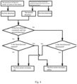
- the judging the safety of an operation which may be performed on an operating arm based on the safety judging basis direction vector includes: judging that the operation of unfolding the operating arm increases safety and the operation of folding the operating arm increases risk under the condition that the direction of the first direction vector is consistent with the direction of the second direction vector and the direction of the third direction vector is vertically upward; judging that the operation of unfolding the operating arm increases risk and the operation of folding the operating arm increases safety under the condition that the direction of the first direction vector is consistent with the direction of the second direction vector and the direction of the third direction vector is not vertically downward; judging that the operation of unfolding the operating arm increases safety and the operation of folding the operating arm increases risk under the condition that the direction of the first direction vector is inconsistent with the second direction vector and the direction of the third direction vector is vertically downward; and judging that the operation of unfolding the operating arm increases risk and the operation of folding the operating arm increases safety under the condition that the direction of the first direction vector is inconsistent with the direction of the second direction vector and the
- the first action is the operation of unfolding the boom and the reverse action of the second action.
- the first action on the operating arm can generate a movement for making the terminal end of the operating arm upward.
- the second action is an operation of folding the boom and the reverse action of the first action.
- the second action on the operating arm can generate a movement for making the terminal end of the operating arm downward.
- the driving action on any k-th arm (0 ⁇ k ⁇ N) is dangerous if the center of gravity of the whole arm is far away from the bearing area of the mobile machinery because of the action, and the action direction of the arm caused by the driving is a dangerous direction, and the opposite direction is a safe direction.
- the "bearing area” is an area where the mobile machine is supported by the ground.
- the bearing area of the pump truck is the area determined by connection lines of support points of four support legs;
- the bearing area of an aerial work platform is the area defined by its bearing tires;
- the bearing area of a construction robot is the support bearing area determined by the combination of support legs and tires.
- the bearing area is a convex polygon.
- the center of gravity of the boom of the mobile device is far away from its bearing area, which means that the center of gravity of the whole mobile device is far away from its bearing area.
- the structural design of mobile equipment also needs to meet the adaptation of the bearing area and the extension range (center of gravity range) of the boom, so the boundary of the bearing area is the safe boundary of anti-tilting of the mobile equipment, and the initial state must be safe, that is to say, the center of gravity of the whole machine integrated with the weight of the boom is located in the bearing area. Therefore, the distance of the center of gravity of the boom from the bearing area will make the center of gravity of the whole machine close to the edge of the bearing area and eventually exceed the bearing area, which will lead to the danger of tilting. Therefore, the action of each arm has a action direction that is a dangerous direction (and a safe direction). Accurate identification of the action safety of each arm is the basis of arm control to prevent tilting.
- the position of the center of mass of the full boom and the position of the center of mass from the k arm to the terminal arm are determined, wherein the position of the center of mass of the full boom is the position of the full center of mass in the embodiment of the invention, the k arm represents the operable arm, that is, the operating arm in the embodiment of the invention, and the position of the center of mass from the k arm to the terminal arm is the position of the combined center of mass in the embodiment of the invention.
- the method of determining the position of the center of mass can refer to the method described in the above embodiments.
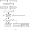
- a first direction (first direction vector), a second direction (second direction vector), and a third direction (third direction vector) are determined, wherein the method of determining the direction vector can refer to the method described in the above embodiments.
- the third direction is upward under the condition that the first direction and the second direction are consistent, the first action increases safety and the second action increases risk; if the third direction is not upward under the condition that the first direction and the second direction are consistent, the first action increases risk and the second action increases safety.
- the third direction is downward when the first direction and the second direction are inconsistent, the first action increases safety and the second action increases risk; if the third direction is not downward when the first direction and the second direction are inconsistent, the first action increases risk and the second action increases safety.
- the arm postures and arm parameters are acquired, that is, the parameters of each arm in the boom are acquired as described in above the embodiment.
- the position of the center of mass of the full boom and the position of the combined center of mass from the k arm to the terminal arm are determined, that is, the position of the full center of mass and the position of the combined center of mass are determined as described in the above embodiments.
- the action safety of the k arm is judged, that is, the safety of an action which may be performed on the operating arm is judged, referring to the judging method described in the above-described embodiment in combination with Fig. 4 .
- the definitions of the first action and the second action for example are understood in conjunction with the introduction with respect to Fig. 4 . It should be noted that the definitions of the first action and the second action are exemplary and are not intended to limit the present invention.
- the trigger condition is that the stability safety factor of the whole vehicle judged based on the tilting torque is less than a certain threshold, and when the condition is met, the restriction on the boom action to the dangerous direction is activated; based on the relationship between the support area and the projection position of the center of gravity, when the center of gravity falls outside the limited area, the restriction on the boom action to the dangerous direction is activated; based on the angle relationship of the boom, when the angle combination exceeds the preset angle combination range, the restriction on the boom action to the dangerous direction is activated.
- the judgment of whether the boom action is required to be restricted is not in particular order with the judgment of the safety of the operation that can be performed on the operating arm, but when the boom operation is controlled, it is necessary to first know the judgment result of whether the boom action is required to be restricted, and then operate the boom according to the judgment result.
- the safety of boom operation is pre-judged in real time, and its control real-time response does not need to temporarily calculate the motion safety after the demand of "limiting boom action" is activated, which greatly saves the judgment delay caused by the operation time of the system, makes the system have high response timeliness, and enhances the safety control effect and the safety of equipment anti-tilting.
- the method before judging the safety of an operation which may be performed on the operating arm, the method further includes: judging whether any operation which may be performed on any arm of the operating arm is safe and risk-free; and not judging the safety of an operation which may be performed on the operating arm and allowing an unfolding or folding operation on the operating arm in the case that any operation which may be performed on any arm of the operating arm is safe and risk-free.
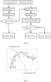
- Fig. 6 is a logic schematic diagram of a method for judging safety of an operation which may be performed on a boom of engineering machinery provided by another embodiment of the invention.
- Fig. 6 differs from the method shown in Fig. 5 in that in Fig. 6 full boom action safety judgment is added.
- the operation of the k arm allows the first action and the second action if the result of the full boom action safety judgment is that any movement for arms is safe and risk-free; and not that any movement for arms is safe and risk-free, it goes back to the method shown in Fig. 5 .
- the thinking of judging the action safety of the whole vehicle boom can be as follows: according to the supporting area and a new area formed by a certain margin far away from its boundary, if the center of gravity of the whole vehicle falls in this area, it is considered that it is safe and risk-free to move one or more arms of the boom at will, wherein the manner described herein does not include measuring only the leg reaction force and judging safety only from the leg reaction force relationship.
- the safety judgment is divided into two modules, and the judgment part on the right side of Fig. 6 does not need to be carried out under any operation, thus saving system operation.
- "Arm k Action Safety Judgment" will be decomposed into more than one judgment function module.
- the calculation of the subsequent judgment module (the judgment part on the right side of Fig. 6 ) can be avoided, thus saving computing power.
- the solution shown in Fig. 6 can be used as a technical improvement solution of the pumping equipment adopting the prior art, that is, the judgment part shown on the right side of Fig. 6 is added to the original control program structure to realize the judgment and control of the action safety of a single arm.
- the method further includes presenting the safety of an operation which may be performed on the operating arm in at least one of the following ways: a display screen interface, an indicator light, sound, a symbol and vibration.
- a display screen interface an indicator light, sound, a symbol and vibration.
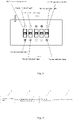
- the dashed box represents the visual human-computer interface window environment
- the first indication state is used to indicate the first state of the arm operation executability (the operation will be responded to)
- the second indication state is used to indicate the second state of the arm operation executability (the operation will not be responded to).
- the first indication state and the second indication state should be different, and should be presented with high contrast colors or states of flashing and non-flashing.
- An example is to indicate the safety of the operation which may be performed on the operating arm with an indicator light, and the tendencies towards safety and danger can be indicated by indicator lights of different colors.
- a red indicator light indicates that the boom operation corresponding to the indication symbol is unexecutable or tends to be dangerous
- a green indicator light indicates that the boom operation corresponding to the indication symbol is executable or tends to be safe.
- the indication symbol may take a variety of forms, for example, it may also be marked by a symbol or text of "lock"- "unlock”, “forbidden” -"allow”.
- the human-computer interaction function i.e., presenting the safety of the operation which may be performed on the operating arm
- the human-computer interaction system can still independently form a reminder and guidance to the operator, avoid the dangerous operation, and then ensure the operation (posture) safety of the boom of the engineering machinery (for example, the mobile machinery).
- the "display" mode of human-computer interaction can be realized on the device monitor, display screen, remote controller display screen, or other display terminals (such as mobile phones with terminal APP), and can also be presented in the form of indicator lights on the remote controller.
- the 1a indicator light corresponds to the executability of the first operating handle in the direction a
- the 1b indicator light corresponds to the executability of the first operating handle in the direction b
- other handles and indicator lights are arranged in the same way.
- Indicator lights indicate the executability of a certain direction through different states.
- an example is that all indicator lights are red, and when the indicator lights are on, it indicates that the operation cannot (is not allowed) to be performed or increases risk; when the indicator lights are off, it indicates that the operation is unlimited, which can be executed or increase safety.
- another example is that all indicator lights are green, and when the indicator lights are on, it indicates that the handle operation in this direction can (allow) be performed or increase safety; when the indicator lights are off, it indicates that the operation is restricted, so as not to perform or increase risk.
- the technical solution provided by the embodiment of the invention does not exclude the superposition use of other human-computer interaction means, such as sound alarm, vibration reminder and the like.
- Display is not the only man-machine interaction way of the technical solution provided by the embodiment of the invention, and the sound alarm mode is preferably supplemented to strengthen the reminder to the operator.
- the alarm function occurs when a restriction is taken or when it is judged that the restriction needs to be taken by a person (boom operation).
- control system portion corresponding to the technical solution provided by the embodiment of the present invention can be understood with reference to the following exemplary introduction.
- the system structure includes: the boom posture detection unit is connected with the calculation control unit; the boom action control unit is connected with the calculation control unit; the calculation control unit is connected with the boom action execution unit.
- the boom posture detection unit is configured to detect the posture of each boom, and the realization modes include boom angle detection (inclination angle sensor or included angle potentiometer or rotary encoder, etc.) or boom cylinder stroke detection sensor (linear encoder or pull wire sensor or laser distance sensor, etc.);
- the boom action control unit is used for the operator to send the control instruction of the boom action to the mobile device, and the realization mode is remote controller or program-controlled intelligent control device (pre-programmed, triggered by the operator);
- the calculation control unit receives data and signals from the boom posture detection unit and the boom action control unit, and carry out calculation processing: after the boom posture data from the boom posture detection unit is output to the calculation control unit, the safety of the boom action direction can be judged according to the boom structure and an electro-hydraulic system, the judgment result of the boom posture detection unit and the calculation control
- the system only needs the boom posture detection unit and the calculation control unit.
- the actual system consists of the boom posture detection unit, the boom action control unit, the calculation control unit and the boom action execution unit. If the calculation and control of safety judgment are not realized by the same device, the calculation control unit is divided into a calculation judgment unit and a control unit, the calculation judgment unit and the control unit are connected through communication, and the calculation judgment unit outputs the judgment result of the safety direction of the boom action to the control unit.
- the system structure is as follows: the boom posture detection unit and the boom action control unit are connected in parallel with the calculation judgment unit, the calculation judgment unit is connected with the control unit, and the control unit is connected with the boom action execution unit.
- another aspect of the embodiment of the present invention provides an apparatus for determining the safety of an operation which may be performed on a boom of an engineering machinery.
- Fig. 9 is a structural schematic diagram illustrating an apparatus for judging the safety of an operation which may be performed on a boom of engineering machinery provided by another embodiment of the present invention.
- the apparatus includes a parameter acquisition module 1, a center of mass position determination module 2, a direction vector determination module 3, and a safety judging module 4.
- the parameter acquisition module 1 is configured to acquire the parameters of each arm in the boom, wherein, the parameters include inclination angle, arm length and mass;
- the center of mass position determination module 2 is configured to determine, based on the acquired parameters, a position of the full center of mass of the boom and a position of the combined center of mass from an operating arm to a terminal arm;
- the direction vector determination module 3 is configured to determine a safety judging basis direction vector based on the position of the full center of mass and the position of the combined center of mass;
- the safety judgment module 4 is configured to judge the safety of an operation which may be performed on an operating arm based on the safety judging basis direction vector.
- the safety judging basis direction vector includes a first direction vector, a second direction vector, and a third direction vector, wherein the first direction vector is a projection vector in a horizontal plane of a direction vector from a beginning end of the boom to the position of the full center of mass, the second direction vector is a projection vector in the horizontal plane of a direction vector from a beginning end of the operating arm to the position of the combined center of mass, and the third direction vector is a projection vector in a vertical direction perpendicular to the horizontal plane of a direction vector from the beginning end of the operating arm to the position of the combined center of mass.
- the safety judging module before judging the safety of an operation which may be performed on the operating arm, is further configured to: judging whether any operation which may be performed on any arm of the boom is safe and risk-free; and not judging the safety of any operation which may be performed on the operating arm and allowing an unfolding or folding operation on the operating arm in the case that an operation which may be performed on any arm of the boom is safe and risk-free.
- the apparatus further including a presentation module configured to present the safety of an operation which may be performed on the operating arm in at least one of the following ways: a display screen interface, an indicator light, sound, a symbol and vibration.
- a presentation module configured to present the safety of an operation which may be performed on the operating arm in at least one of the following ways: a display screen interface, an indicator light, sound, a symbol and vibration.
- Another aspect of the embodiment of the present invention also provides engineering machinery including the device described in the above embodiment.
- another aspect of the embodiment of the present invention also provides a machine-readable storage medium which stores instructions for causing a machine to perform the method described in the above-described embodiment.
Landscapes
- Engineering & Computer Science (AREA)
- Mechanical Engineering (AREA)
- Architecture (AREA)
- Structural Engineering (AREA)
- Civil Engineering (AREA)
- Automation & Control Theory (AREA)
- Life Sciences & Earth Sciences (AREA)
- Geology (AREA)
- Robotics (AREA)
- Jib Cranes (AREA)
- Forklifts And Lifting Vehicles (AREA)
- Component Parts Of Construction Machinery (AREA)
Applications Claiming Priority (2)
| Application Number | Priority Date | Filing Date | Title |
|---|---|---|---|
| CN202010468758.3A CN111761574B (zh) | 2020-05-28 | 2020-05-28 | 判断臂架可进行的操作的安全性的方法和装置及工程机械 |
| PCT/CN2020/094054 WO2021237765A1 (fr) | 2020-05-28 | 2020-06-03 | Procédé et appareil pour déterminer la sécurité d'une manœuvre qui peut être effectuée par une flèche de grue, et engins de chantier |
Publications (3)
| Publication Number | Publication Date |
|---|---|
| EP4159384A1 true EP4159384A1 (fr) | 2023-04-05 |
| EP4159384A4 EP4159384A4 (fr) | 2023-11-29 |
| EP4159384B1 EP4159384B1 (fr) | 2026-01-28 |
Family
ID=72719729
Family Applications (1)
| Application Number | Title | Priority Date | Filing Date |
|---|---|---|---|
| EP20937552.6A Active EP4159384B1 (fr) | 2020-05-28 | 2020-06-03 | Procédé et appareil pour déterminer la sécurité d'une manoeuvre qui peut être effectuée par une flèche, et engins de chantier |
Country Status (4)
| Country | Link |
|---|---|
| US (1) | US12103826B2 (fr) |
| EP (1) | EP4159384B1 (fr) |
| CN (1) | CN111761574B (fr) |
| WO (1) | WO2021237765A1 (fr) |
Families Citing this family (6)
| Publication number | Priority date | Publication date | Assignee | Title |
|---|---|---|---|---|
| CN112936242B (zh) * | 2021-01-29 | 2022-07-26 | 中联重科股份有限公司 | 判断臂架操作安全性的方法、装置及工程机械 |
| CN116448030A (zh) * | 2022-01-10 | 2023-07-18 | 库卡机器人(广东)有限公司 | 测量系统及其控制方法、控制装置、可读存储介质 |
| DE102022116319A1 (de) * | 2022-06-30 | 2024-01-04 | Liebherr-Mischtechnik Gmbh | Verfahren zur Überwachung der Standsicherheit einer Arbeitsmaschine |
| CN116290783A (zh) * | 2022-11-25 | 2023-06-23 | 徐州威卡电子控制技术有限公司 | 一种混凝土臂架类泵车防倾翻控制系统及其方法 |
| CN116081506B (zh) * | 2023-02-10 | 2025-05-02 | 三一汽车制造有限公司 | 臂架收回方法、臂架系统及作业机械 |
| CN116079743B (zh) * | 2023-03-24 | 2024-06-14 | 合肥工业大学 | 一种移动机械臂系统建模及防倾覆控制方法 |
Family Cites Families (20)
| Publication number | Priority date | Publication date | Assignee | Title |
|---|---|---|---|---|
| US6518519B1 (en) * | 2000-08-30 | 2003-02-11 | Caterpillar Inc | Method and apparatus for determining a weight of a payload |
| JP2007138504A (ja) * | 2005-11-17 | 2007-06-07 | Shin Caterpillar Mitsubishi Ltd | 作業機械における作業アームデータ補正方法および作業機械 |
| CN102906347B (zh) * | 2010-05-24 | 2015-04-22 | 日立建机株式会社 | 作业机械的安全装置 |
| CN102390779B (zh) * | 2011-11-04 | 2014-01-29 | 三一重工股份有限公司 | 起重机倾翻状态检测方法及检测装置 |
| CN102514550B (zh) * | 2011-12-20 | 2014-04-30 | 长沙中联消防机械有限公司 | 工程机械以及其安全状态确定方法、装置和系统 |
| CN102589493B (zh) * | 2012-02-08 | 2014-05-21 | 三一重工股份有限公司 | 臂架系统、工程机械和臂架系统末端位置参数获取方法 |
| DE102012004739A1 (de) * | 2012-03-08 | 2013-09-12 | Liebherr-Werk Nenzing Gmbh | Kran und Verfahren zur Kransteuerung |
| CN102826469B (zh) * | 2012-08-24 | 2015-05-13 | 三一重工股份有限公司 | 防倾翻装置及工程机械 |
| ES2785273T3 (es) * | 2012-10-24 | 2020-10-06 | Sandvik Mining & Construction Oy | Vehículo minero y método para mover el brazo |
| CN102915045B (zh) * | 2012-10-31 | 2015-01-07 | 中联重科股份有限公司 | 一种臂架类工程车辆的控制方法及装置 |
| WO2015186180A1 (fr) * | 2014-06-02 | 2015-12-10 | 株式会社小松製作所 | Système de commande de machine de construction, machine de construction, et méthode de commande de machine de construction |
| US9475193B2 (en) * | 2015-02-09 | 2016-10-25 | Harris Corporation | Unmanned ground vehicle stability control |
| CA2951674A1 (fr) * | 2015-12-15 | 2017-06-15 | Joy Global Surface Mining Inc | Systeme et methode d'estimation de charge d'une machine industrielle |
| CN106737549B (zh) * | 2016-12-21 | 2019-05-31 | 深圳中智科创机器人有限公司 | 一种移动机器人及其防倾覆方法和装置 |
| CN108264690A (zh) | 2017-12-06 | 2018-07-10 | 淮北市天相电缆有限责任公司 | 一种航空电缆用耐高温阻燃电缆护套料 |
| DE102018204079A1 (de) * | 2018-03-16 | 2019-09-19 | Putzmeister Engineering Gmbh | Autobetonpumpe und Verfahren zur stabilitätsrelevanten Steuerung einer Autobetonpumpe |
| CN110520575B (zh) * | 2018-03-22 | 2021-11-02 | 日立建机株式会社 | 作业机械 |
| CN111868338B (zh) * | 2018-03-22 | 2022-07-26 | 住友重机械工业株式会社 | 挖土机 |
| CN109454616A (zh) * | 2018-09-18 | 2019-03-12 | 华中科技大学 | 一种移动操作机器人倾翻稳定性判断方法及控制方法 |
| CN110673653B (zh) * | 2019-09-12 | 2020-07-17 | 中联重科股份有限公司 | 工程机械的防倾翻控制方法、装置及该工程机械 |
-
2020
- 2020-05-28 CN CN202010468758.3A patent/CN111761574B/zh active Active
- 2020-06-03 EP EP20937552.6A patent/EP4159384B1/fr active Active
- 2020-06-03 US US17/621,120 patent/US12103826B2/en active Active
- 2020-06-03 WO PCT/CN2020/094054 patent/WO2021237765A1/fr not_active Ceased
Also Published As
| Publication number | Publication date |
|---|---|
| EP4159384A4 (fr) | 2023-11-29 |
| EP4159384B1 (fr) | 2026-01-28 |
| US12103826B2 (en) | 2024-10-01 |
| CN111761574A (zh) | 2020-10-13 |
| CN111761574B (zh) | 2022-08-02 |
| WO2021237765A1 (fr) | 2021-12-02 |
| US20220348443A1 (en) | 2022-11-03 |
Similar Documents
| Publication | Publication Date | Title |
|---|---|---|
| EP4159384B1 (fr) | Procédé et appareil pour déterminer la sécurité d'une manoeuvre qui peut être effectuée par une flèche, et engins de chantier | |
| CN109160419B (zh) | 一种建筑施工塔吊机群防碰撞中央处理装置 | |
| CN103613014B (zh) | 塔式起重机防碰撞系统、方法、装置及塔式起重机 | |
| EP2436637B1 (fr) | Équipement de détection de pose de crochet et grue | |
| CN104627842B (zh) | 一种臂架式起重机吊装作业防碰撞方法及系统 | |
| KR102369031B1 (ko) | 실시간 크레인 충돌방지 모니터링 장치 및 그 방법 | |
| CN109095355A (zh) | 作业空间防碰撞方法和系统、探测设备和控制设备 | |
| JP2003118981A (ja) | クレーン接近警報装置 | |
| CN106586838A (zh) | 起重机的作业控制方法、系统及起重机 | |
| CN117105097B (zh) | 一种智能塔机控制系统、方法及控制设备 | |
| US20210269285A1 (en) | Crane with an anti-collision device and method for installing such an anti-collision device | |
| CN108687748A (zh) | 具有外力显示功能的机器人系统、处理装置以及示教操作盘 | |
| CN115140665B (zh) | 施工机械的周围监视装置 | |
| CN113898024A (zh) | 一种挖掘机动作的防碰撞控制方法 | |
| KR102371088B1 (ko) | 산업 현장의 중장비 간 충돌 예방 방법과 이에 대한 관제 시스템 | |
| KR20230087783A (ko) | 디지털 트윈 기반 안전 교육 시스템 | |
| RU2345944C1 (ru) | Способ повышения безопасности работы грузоподъемного крана (варианты) | |
| CN119580467A (zh) | 吊装作业安全预警方法、装置、存储介质及电子设备 | |
| CN113213341A (zh) | 一种室外起重机区域防撞系统及其方法 | |
| US12110657B2 (en) | Construction equipment | |
| KR20180037657A (ko) | 고소작업차 붐의 3차원 자동안착 시스템 | |
| CN111583591A (zh) | 一种起重机械安全报警方法和装置 | |
| JPH08268681A (ja) | 作業車の作業状態模擬確認装置 | |
| JP2644352B2 (ja) | クレーンの安全装置 | |
| JPH0517971A (ja) | 建設作業用機械の安全装置 |
Legal Events
| Date | Code | Title | Description |
|---|---|---|---|
| STAA | Information on the status of an ep patent application or granted ep patent |
Free format text: STATUS: THE INTERNATIONAL PUBLICATION HAS BEEN MADE |
|
| PUAI | Public reference made under article 153(3) epc to a published international application that has entered the european phase |
Free format text: ORIGINAL CODE: 0009012 |
|
| STAA | Information on the status of an ep patent application or granted ep patent |
Free format text: STATUS: REQUEST FOR EXAMINATION WAS MADE |
|
| 17P | Request for examination filed |
Effective date: 20211216 |
|
| AK | Designated contracting states |
Kind code of ref document: A1 Designated state(s): AL AT BE BG CH CY CZ DE DK EE ES FI FR GB GR HR HU IE IS IT LI LT LU LV MC MK MT NL NO PL PT RO RS SE SI SK SM TR |
|
| DAV | Request for validation of the european patent (deleted) | ||
| DAX | Request for extension of the european patent (deleted) | ||
| REG | Reference to a national code |
Ref country code: DE Ref legal event code: R079 Free format text: PREVIOUS MAIN CLASS: B25J0009160000 Ipc: E04G0021040000 Ref country code: DE Ref legal event code: R079 Ref document number: 602020066400 Country of ref document: DE Free format text: PREVIOUS MAIN CLASS: B25J0009160000 Ipc: E04G0021040000 |
|
| STAA | Information on the status of an ep patent application or granted ep patent |
Free format text: STATUS: EXAMINATION IS IN PROGRESS |
|
| A4 | Supplementary search report drawn up and despatched |
Effective date: 20231027 |
|
| RIC1 | Information provided on ipc code assigned before grant |
Ipc: B66F 17/00 20060101ALI20231023BHEP Ipc: E04G 21/04 20060101AFI20231023BHEP |
|
| 17Q | First examination report despatched |
Effective date: 20231110 |
|
| GRAP | Despatch of communication of intention to grant a patent |
Free format text: ORIGINAL CODE: EPIDOSNIGR1 |
|
| STAA | Information on the status of an ep patent application or granted ep patent |
Free format text: STATUS: GRANT OF PATENT IS INTENDED |
|
| INTG | Intention to grant announced |
Effective date: 20250905 |
|
| GRAS | Grant fee paid |
Free format text: ORIGINAL CODE: EPIDOSNIGR3 |
|
| GRAA | (expected) grant |
Free format text: ORIGINAL CODE: 0009210 |
|
| STAA | Information on the status of an ep patent application or granted ep patent |
Free format text: STATUS: THE PATENT HAS BEEN GRANTED |
|
| AK | Designated contracting states |
Kind code of ref document: B1 Designated state(s): AL AT BE BG CH CY CZ DE DK EE ES FI FR GB GR HR HU IE IS IT LI LT LU LV MC MK MT NL NO PL PT RO RS SE SI SK SM TR |
|
| REG | Reference to a national code |
Ref country code: CH Ref legal event code: F10 Free format text: ST27 STATUS EVENT CODE: U-0-0-F10-F00 (AS PROVIDED BY THE NATIONAL OFFICE) Effective date: 20260128 Ref country code: GB Ref legal event code: FG4D |
|
| REG | Reference to a national code |
Ref country code: DE Ref legal event code: R096 Ref document number: 602020066400 Country of ref document: DE |
|
| REG | Reference to a national code |
Ref country code: IE Ref legal event code: FG4D |