EP4159491B1 - Adaptateur de buse pour valve presta - Google Patents
Adaptateur de buse pour valve presta Download PDFInfo
- Publication number
- EP4159491B1 EP4159491B1 EP21200359.4A EP21200359A EP4159491B1 EP 4159491 B1 EP4159491 B1 EP 4159491B1 EP 21200359 A EP21200359 A EP 21200359A EP 4159491 B1 EP4159491 B1 EP 4159491B1
- Authority
- EP
- European Patent Office
- Prior art keywords
- nozzle adapter
- connection seat
- outlet
- inlet
- control element
- Prior art date
- Legal status (The legal status is an assumption and is not a legal conclusion. Google has not performed a legal analysis and makes no representation as to the accuracy of the status listed.)
- Active
Links
Images


Classifications
-
- B—PERFORMING OPERATIONS; TRANSPORTING
- B60—VEHICLES IN GENERAL
- B60C—VEHICLE TYRES; TYRE INFLATION; TYRE CHANGING; CONNECTING VALVES TO INFLATABLE ELASTIC BODIES IN GENERAL; DEVICES OR ARRANGEMENTS RELATED TO TYRES
- B60C29/00—Arrangements of tyre-inflating valves to tyres or rims; Accessories for tyre-inflating valves, not otherwise provided for
- B60C29/06—Accessories for tyre-inflating valves, e.g. housings, guards, covers for valve caps, locks, not otherwise provided for
-
- F—MECHANICAL ENGINEERING; LIGHTING; HEATING; WEAPONS; BLASTING
- F04—POSITIVE - DISPLACEMENT MACHINES FOR LIQUIDS; PUMPS FOR LIQUIDS OR ELASTIC FLUIDS
- F04B—POSITIVE-DISPLACEMENT MACHINES FOR LIQUIDS; PUMPS
- F04B39/00—Component parts, details, or accessories, of pumps or pumping systems specially adapted for elastic fluids, not otherwise provided for in, or of interest apart from, groups F04B25/00 - F04B37/00
- F04B39/10—Adaptations or arrangements of distribution members
-
- F—MECHANICAL ENGINEERING; LIGHTING; HEATING; WEAPONS; BLASTING
- F16—ENGINEERING ELEMENTS AND UNITS; GENERAL MEASURES FOR PRODUCING AND MAINTAINING EFFECTIVE FUNCTIONING OF MACHINES OR INSTALLATIONS; THERMAL INSULATION IN GENERAL
- F16K—VALVES; TAPS; COCKS; ACTUATING-FLOATS; DEVICES FOR VENTING OR AERATING
- F16K15/00—Check valves
- F16K15/20—Check valves specially designed for inflatable bodies, e.g. tyres
Definitions
- the present invention relates to a nozzle adapter connected with an air inflator valve of a tire of a vehicle to inflate air into the tire, and more particularly to connect with and remove from a Presta valve at a high pressure quickly.
- an inflation valve having a check valve is fixed on the tire, and a pressurized pump inflates the air, wherein the pressurized pump has the nozzle adapter to communicate with the inflation valve.
- a fixing device of the nozzle adapter is switched so that the nozzle adapter is connected with the inflation valve, and the fixing device is locked so that the nozzle adapter engages with the inflation valve, thus removing a hand to inflate the air.
- the fixing device is used in following three manners:
- the nozzle adapter is operated manually to connect with the inflation valve, and it is required to operate the fixing device, thus having troublesome operation.
- the inventor invented a joint structure of an air valve disclosed in US 10,166,825 B2 , wherein the nozzle adapter is connected with the inflation valve to inflate the air, and the inflation valve is inserted by a conduit of an outlet segment of the nozzle adapter to inflate the air easily. Thereafter, the nozzle adapter is removed after pressing a manual operation portion of a control element to have an easy operation, and multiple teeth engage with threads of the inflation valve securely at the high pressure.
- a joint structure is merely applicable for Schrader valve instead of Presta valve.
- the present invention has arisen to mitigate and/or obviate the afore-described disadvantages.
- the primary object of the present invention is to provide a nozzle adapter to be connected with a Presta valve which is operated with one hand easily and conveniently to connect with the Presta valve, such that after inflating air, the nozzle adapter is removed from the Presta valve with one hand, and the Presta valve is inserted into an outlet of the nozzle adapter automatically, wherein the nozzle adapter is removed from the Presta valve by using a controlling means easily and conveniently.
- Another object of the present invention is to provide a nozzle adapter to be connected with a Presta valve which is applied to inflate the air at a high pressure, wherein when an inflation pressure is excessive, the Presta valve is pushed outward by the air pressure, and two engaging portions of two control elements are pulled to a screwing portion of the Presta valve so that two engaging portions engage with a screwing portion of the Presta valve more forcefully, thus using the Presta valve to inflate the air at the high pressure appropriately.
- a nozzle adapter provided by the present invention contains: a connection seat, at least one control element, at least one returning element, a seal cover, and a controlling means.
- the connection seat includes an imaginary axis line defined on a center of the connection seat, an inlet defined on a first end of the imaginary axis line, an outlet formed on a second end of the imaginary axis line, an air stop ring received in the outlet, a conduit defined between the inlet and the outlet, an engagement position defined in the conduit, a coupling slot defined on the connection seat, and a stopping means formed outside the coupling slot.
- the coupling slot has at least one controlling trench defined outside the conduit, the at least one controlling trench extends to the engagement position via the inlet, and a respective controlling trench has a rotatable portion extending to the outlet adjacent to the air stop ring.
- the at least one control element is accommodated in the at least one controlling trench.
- a respective control element has a fixing shaft extending on a first end thereof and connected with the rotatable portion, such that the at least one control element swings along the fixing shaft arcuately, the respective control element has an engaging portion extending from a second end thereof and has a controlled portion. The engaging portion is toothed and extends out of the engagement position.
- the at least one returning element is arranged on the at least one control element so that the engaging portion is pushed into the engagement position.
- the seal cover is fixed outside the coupling slot of the connection seat, and an airtight space is defined in the coupling slot by mating with the stopping means.
- the controlling means is mounted on a center of the connection seat opposite to the inlet and in the conduit of the airtight space to move with the controlled portion.
- the controlling means extends out of the connection seat and is switched manually, when the controlling means is switched manually, the controlled portion is moved so that the engaging portion of the respective control element moves outward away from the engagement position.
- the nozzle adapter is to be connected with the Presta valve, and the Presta valve includes an inlet portion, a screwing portion, and a neck portion.
- the Presta valve is inserted into the outlet, the neck portion is engaged matingly by the air stop ring of the Presta valve, and the screwing portion is engaged by the engaging portion at the engagement position. The screwing portion moves forward from the outlet to the inlet.
- a nozzle adapter to be connected with a Presta valve according to a preferred embodiment of the present invention, a nozzle adapter 1 is communicated with the Presta valve 2 to inflate air, the Presta valve 2 comprises an inlet portion 2A, a screwing portion 2B, and a neck portion 2C (as shown in FIGS. 7-11 ).
- the nozzle adapter 1 includes a connection seat 10, a cap 10A, a lid 20, at least one control element 30, at least one returning element 40, a seal cover 50, and a controlling means 60.
- connection seat 10 includes an imaginary axis line L1 defined on a center thereof, an inlet 11 defined on a first end of the imaginary axis line L1, and an outlet 12 formed on a second end of the imaginary axis line L1, an air stop ring 13 and a locking ring 13A which are received in the outlet 12.
- the air stop ring 13 is made of rubber and has a protrusion 131 formed on an inner wall thereof, the locking ring 13A has a first threaded portion 13B formed on an outer wall thereof, the connection seat 10 has a second threaded portion 121 formed on an inner wall of the outlet 12 thereof, such that the first threaded portion 13B of the locking ring 13A is screwed with the second threaded portion 121 of the outlet 12 so that the locking ring 13A is fixed on the air stop ring 13.
- the connection seat 10 includes two grooves 14 defined on the first end of the imaginary axis line L1, a third threaded portion 15 screwed with the cap 10A, and a fourth threaded portion 10B formed on the cap 10A, wherein the fourth threaded portion 10B of the cap 10A is screwed with the third threaded portion 15, a conduit 16 defined between the inlet 11 and the outlet 12, an engagement position 161 defined in the conduit 16, a coupling slot 17 defined on the connection seat 10, and a stopping means 18 formed outside the coupling slot 17, wherein the stopping means 18 is two O-shaped rings 181, and the two O-shaped rings 181 are engaged on the cap 10A of the connection seat 10.
- the coupling slot 17 has at least one controlling trench 19 defined outside the conduit 16. In this embodiment, two controlling trenches 19 extend to the engagement position 161 via the inlet 11, wherein a respective controlling trench 19 has a rotatable portion 191 extending to the outlet 12 adjacent to the air stop ring 13.
- the lid 20 covers the coupling slot 17 of the connection seat 10 to close the two controlling trenches 19.
- two control elements 30 are accommodated in the two controlling trenches 19, wherein a respective control element 30 has a fixing shaft 31 extending on a first end thereof and connected with the rotatable portion 191, such that the control element 30 swings along the fixing shaft 31 arcuately.
- the respective control element 30 has an engaging portion 32 extending from a second end thereof and has a controlled portion 33, wherein the engaging portion 32 is toothed and extends out of the engagement position 161, and the engaging portion 32 has a tilted guide face 321 formed proximate to the outlet 12.
- the two returning elements 40 are two spring arranged on the two control elements 30 so that two tilted guide faces 321 of the two control elements 30 are pushed into the engagement position 161 by the two returning elements 40.
- the seal cover 50 is fixed outside the coupling slot 17 of the connection seat 10, and an airtight space X is defined in the coupling slot 17 by mating with the stopping means 18.
- the seal cover 50 is fitted on an outer wall of the connection seat 10 and mates with the two O-shaped rings 181.
- the seal cover 50 includes an inlet tube 51 received in the airtight space X and communicate with the inlet 11 and the conduit 16, wherein the seal cover 50 further includes two slidable posts 52 mounted on an inner wall thereof, and a cylindrical actuation portion 53 is defined between the two slidable posts 52.
- the cylindrical actuation portion 53 has two confining sections 531 configured to drive the two controlled portions 33 of the two control elements 30 to move, and the slidable posts 52 are slidably received and slide in the two grooves 14 of the connection seat 10 and are limited by the cap 10A.
- the controlling means 60 is mounted on a center of the connection seat 10 opposite to the inlet 11 and in the conduit 16 of the airtight space X to move with the controlled portion 33, wherein the controlling means 60 extends out of the connection seat 10 and is switched manually.
- the controlling means 60 is switched manually, the controlled portion 33 is moved.
- the controlling means 60 is to slide the seal cover 50 on the connection seat 10.
- the seal cover 50 moves away from the outlet 12
- the two confining sections 531 of the seal cover 50 push the two controlled portions 33 of the two control elements 30 outward so that two engaging portions 32 of the two control elements 30 move outward away from the engagement position 161, and the two returning elements 40 are pressed.
- the Presta valve 2 When inflating the air via the Presta valve 2 by using the nozzle adapter 1, as shown in FIGS. 7 and 8 , the Presta valve 2 is manually inserted into the outlet 12 with one hand only, and the two engaging portions 32 of the two control elements 30 are pushed by the screwing portion 2B of the Presta valve 2 and the two returning elements 40 to open flexibly, and when the Presta valve 2 is inserted into the predetermined position, the neck portion 2C of the Presta valve 2 is engaged matingly by the air stop ring 13 to produce an airtight state, and the screwing portion 2B of the Presta valve 2 is engaged by the two engaging portions 32 of the two control elements 30 at the engagement position 161.
- the nozzle adapter 1 supplies the air, as illustrated in FIG.
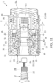
- the seal cover 50 After inflating the air, as shown in FIG. 10 , the seal cover 50 is moved away from the Presta valve 2 with one hand, wherein the seal cover 50 slides on the connection seat 10, the two confining sections 531 of the seal cover 50 push the two controlled portions 33 of the two control elements 30 outward so that the two returning elements 40 are pressed, and the two engaging portions 32 of the two control elements 30 move away from the engagement position 161 outward to remove from the screwing portion 2B of the Presta valve 2, as illustrated in FIG. 11 .
- the seal cover 50 drives the connection seat 10 to move away from the Presta valve 2 so that the nozzle adapter 1 removes from the Presta valve 2, the two returning elements 40 push the two control elements 30 back to an original position, and the two control elements 30 drive the seal cover 50 back to an original position for next using operation.
- the nozzle adapter to be connected with the Presta valve has advantages as follows:
Landscapes
- Engineering & Computer Science (AREA)
- General Engineering & Computer Science (AREA)
- Mechanical Engineering (AREA)
- Lift Valve (AREA)
- Compressors, Vaccum Pumps And Other Relevant Systems (AREA)
Claims (10)
- Adaptateur pour embout (1) à raccorder à une valve Presta (2) caractérisé par le fait qu'il comprend :un siège de raccordement (10) incluant une ligne d'axe imaginaire (L1) définie sur un centre du siège de raccordement (10), une entrée (11) définie sur une première extrémité de la ligne d'axe imaginaire (L1), une sortie (12) formée sur une seconde extrémité de la ligne d'axe imaginaire (L1), une bague d'arrêt de l'air (13) reçue dans la sortie (12), un conduit (16) défini entre l'entrée (11) et la sortie (12), une position d'engagement (161) définie dans le conduit (16), une fente de couplage (17) définie sur le siège de raccordement (10), et un dispositif d'arrêt (18) formé en dehors de la fente de couplage (17), la fente de couplage (17) comportant au moins une tranchée de contrôle (19) définie en dehors du conduit (16), la au moins une tranchée de contrôle (19) s'étend vers la position d'engagement (161) via l'entrée (11), et une tranchée de contrôle respective (19) comporte une partie rotative (191) s'étendant vers la sortie (12) adjacente à la bague d'arrêt de l'air (13) ;au moins un élément de contrôle (30) placé dans la au moins une tranchée de contrôle (19), un élément de contrôle respectif (30) comporte un axe de fixation (31) s'étendant sur une première extrémité de celui-ci et raccordé à la partie rotative (191), de telle sorte que l'au moins un élément de contrôle (30) est adapté pour se balancer de manière précise le long de l'axe de fixation (31),l'élément de contrôle respectif (30) comporte une partie d'engagement (32) s'étendant depuis une seconde extrémité de celui-ci et comporte une partie contrôlée (33), la partie d'engagement (32) est dentée et s'étend à l'extérieur de la position d'engagement (161) ;au moins un élément de retour (40) disposé sur l'au moins un élément de contrôle (30) de telle sorte que la partie d'engagement (32) est poussée dans la position d'engagement (161) ;un couvercle d'étanchéité (50) fixé en dehors de la fente de couplage (17) du siège de raccordement (10), et un espace étanche à l'air (X) étant défini dans la fente de couplage (17) est adapté pour correspondre au dispositif d'arrêt (18) ; etun dispositif de contrôle (60) monté sur un centre du siège de raccordement (10) en face de l'entrée (11) et dans le conduit (16) de l'espace étanche à l'air (X) est adapté pour se déplacer avec la partie contrôlée (33), le dispositif de contrôle (60) s'étend à l'extérieur du siège de raccordement (10) et est adapté pour commuter manuellement ; lorsque le dispositif de contrôle (60) est commuté manuellement, la partie contrôlée (33) est déplacée de telle sorte que la partie d'engagement (32) de l'élément de contrôle respectif (30) se déplace vers l'extérieur en s'éloignant de la position d'engagement (161) ;la valve Presta (2) inclut une partie d'entrée (2A), une partie vissable (2B), et une partie formant col (2C), la valve Presta (2) est adaptée pour être insérée dans la sortie (12), la partie formant col (2C) est adaptée pour être engagée de manière appariée avec la bague d'arrêt de l'air (13) de la valve Presta (2), et la partie vissable (2B) est adaptée pour être engagée par la partie d'engagement (32) sur la position d'engagement (161), la partie vissable (2B) est adaptée pour se déplacer vers l'avant depuis la sortie (12) vers l'entrée (11).
- Adaptateur pour embout (1) selon la revendication 1 caractérisé par le fait qu'il comprend en outre un couvercle (20) recouvrant la fente de couplage (17) du siège de raccordement (10) pour fermer la au moins une tranchée de contrôle (19).
- Adaptateur pour embout (1) selon la revendication 1 caractérisé par le fait qu'il comprend en outre une bague de verrouillage (13A) qui comporte une première partie filetée (13B) formée sur une paroi externe de la bague de verrouillage (13A), le siège de raccordement (10) comporte une deuxième partie filetée (121) formée sur une paroi interne de la sortie (12), de telle sorte que la première partie filetée (13B) de la bague de verrouillage (13A) est vissée sur la deuxième partie filetée (121) de la sortie (12) de manière à ce que la bague de verrouillage (13A) soit fixée sur la bague d'arrêt de l'air (13).
- Adaptateur pour embout (1) selon la revendication 1, caractérisé par le fait que la bague d'arrêt de l'air (13) est composée de caoutchouc et comporte une saillie (131) formée sur une paroi interne de celle-ci.
- Adaptateur pour embout (1) selon la revendication 1 caractérisé par le fait qu'il comprend en outre un capuchon (10A), le siège de raccordement (10) inclut en outre une troisième partie filetée (15) formée sur la première extrémité de la ligne d'axe imaginaire (L1), et le capuchon (10A) comporte une quatrième partie filetée (10B) formée sur celui-ci, la quatrième partie filetée (10B) du capuchon (10A) est vissée sur la troisième partie filetée (15).
- Adaptateur pour embout (1) selon la revendication 1, caractérisé par le fait que le dispositif d'arrêt (18) consiste en deux anneaux en forme de O, et le couvercle d'étanchéité (50) est installé sur une paroi externe du siège de raccordement (10) et s'accouple avec les deux anneaux en forme de O, le couvercle d'étanchéité (50) inclut un tube d'entrée (51) reçu dans l'espace étanche à l'air et communique avec l'entrée (11) et le conduit (16).
- Adaptateur pour embout (1) selon la revendication 5, caractérisé par le fait que le siège de raccordement (10) inclut deux rainures (14) définies sur la première extrémité de la ligne d'axe imaginaire (L1), le couvercle d'étanchéité (50) inclut en outre deux montants coulissants [52) montés sur une paroi interne de celui-ci, et une partie d'actionnement cylindrique (53) est définie entre les deux montants coulissants (52), la partie d'actionnement cylindrique (53) comporte deux sections de confinement (531) configurées pour entraîner les deux parties contrôlées (33) de deux éléments de contrôle (30) à se déplacer, et les deux montants coulissants (52) sont reçus de manière coulissante et coulissent dans les deux rainures (14) du siège de raccordement (10) et sont limités par le capuchon (10A).
- Adaptateur pour embout (1) selon la revendication 1, caractérisé par le fait que le dispositif de contrôle (60) doit faire coulisser le couvercle d'étanchéité (50) sur le siège de raccordement (10).
- Adaptateur pour embout (1) selon la revendication 1, caractérisé par le fait que la partie d'engagement (32) de l'élément de contrôle respectif (30) comporte une face de guidage inclinée formée à proximité de la sortie (12).
- Adaptateur pour embout (1) selon la revendication 1, caractérisé par le fait que l'au moins un élément de retour (40) est un ressort qui est comprimé.
Priority Applications (1)
| Application Number | Priority Date | Filing Date | Title |
|---|---|---|---|
| EP21200359.4A EP4159491B1 (fr) | 2021-09-30 | 2021-09-30 | Adaptateur de buse pour valve presta |
Applications Claiming Priority (1)
| Application Number | Priority Date | Filing Date | Title |
|---|---|---|---|
| EP21200359.4A EP4159491B1 (fr) | 2021-09-30 | 2021-09-30 | Adaptateur de buse pour valve presta |
Publications (3)
| Publication Number | Publication Date |
|---|---|
| EP4159491A1 EP4159491A1 (fr) | 2023-04-05 |
| EP4159491B1 true EP4159491B1 (fr) | 2025-06-25 |
| EP4159491C0 EP4159491C0 (fr) | 2025-06-25 |
Family
ID=78232275
Family Applications (1)
| Application Number | Title | Priority Date | Filing Date |
|---|---|---|---|
| EP21200359.4A Active EP4159491B1 (fr) | 2021-09-30 | 2021-09-30 | Adaptateur de buse pour valve presta |
Country Status (1)
| Country | Link |
|---|---|
| EP (1) | EP4159491B1 (fr) |
Family Cites Families (4)
| Publication number | Priority date | Publication date | Assignee | Title |
|---|---|---|---|---|
| US20140210203A1 (en) * | 2013-01-31 | 2014-07-31 | Eaton Corporation | Fluid Couplling Assembly with Integral Plug Retainer |
| US10166825B2 (en) * | 2016-06-27 | 2019-01-01 | Lung-Kuo Hsu | Joint structure for an air valve |
| CN107542988B (zh) * | 2016-06-27 | 2019-06-11 | 许龙国 | 供充气的气嘴接头 |
| TWI665401B (zh) * | 2018-08-21 | 2019-07-11 | 許龍國 | 氣嘴接頭具自動止氣結構 |
-
2021
- 2021-09-30 EP EP21200359.4A patent/EP4159491B1/fr active Active
Also Published As
| Publication number | Publication date |
|---|---|
| EP4159491A1 (fr) | 2023-04-05 |
| EP4159491C0 (fr) | 2025-06-25 |
Similar Documents
| Publication | Publication Date | Title |
|---|---|---|
| US11867303B2 (en) | Nozzle adapter for Presta valve | |
| EP1170184B1 (fr) | Connecteur de valve de pneumatique | |
| EP4097381B1 (fr) | Système de soupape pneumatique amélioré | |
| US6904932B1 (en) | Pump valve adapter | |
| US20140326345A1 (en) | Connector Structure for a Schrader (American) Valve/Presta (French) Valve | |
| US9511636B2 (en) | Joint structure for an air nozzle | |
| US10166825B2 (en) | Joint structure for an air valve | |
| EP3797979B1 (fr) | Structure de joint de contrôle pour la connexion de buse d'air d'un pneumatique et tuyau de connexion de compresseur d'air | |
| US7032613B2 (en) | Connector for an inflation device compatible with several types of valve | |
| US20180172167A1 (en) | Connector Structure of Air Connector Adapted to Connect Presta (French) Valve and Schrader (American) Valve | |
| WO2023215444A1 (fr) | Système de soupape pneumatique amélioré et ses procédés d'utilisation | |
| US20170009922A1 (en) | Quick Connector Structure for a Pneumatic Valve | |
| EP4159491B1 (fr) | Adaptateur de buse pour valve presta | |
| US5509438A (en) | Air valve adapter | |
| US4623123A (en) | Conduit coupling | |
| US10914421B2 (en) | Push-button grease gun barrel and method of use | |
| US9068670B2 (en) | Valve for an inflatable structure | |
| CN103791128B (zh) | 水平式扳转的充气接头 | |
| EP2770207B1 (fr) | Tête de buse à commutation automatique ayant deux nez de valve et tête de buse de nez simple | |
| CN206036338U (zh) | 两用气嘴接头 | |
| US7624751B2 (en) | Air nozzle for automatically inflatable air cushion | |
| KR100324547B1 (ko) | 퀵타입 커플링 | |
| US20250276672A1 (en) | Tire inflation tool with valve removal function | |
| KR100443937B1 (ko) | 밸브 연결기 | |
| US12297943B2 (en) | Adapter |
Legal Events
| Date | Code | Title | Description |
|---|---|---|---|
| PUAI | Public reference made under article 153(3) epc to a published international application that has entered the european phase |
Free format text: ORIGINAL CODE: 0009012 |
|
| STAA | Information on the status of an ep patent application or granted ep patent |
Free format text: STATUS: REQUEST FOR EXAMINATION WAS MADE |
|
| 17P | Request for examination filed |
Effective date: 20220211 |
|
| AK | Designated contracting states |
Kind code of ref document: A1 Designated state(s): AL AT BE BG CH CY CZ DE DK EE ES FI FR GB GR HR HU IE IS IT LI LT LU LV MC MK MT NL NO PL PT RO RS SE SI SK SM TR |
|
| RBV | Designated contracting states (corrected) |
Designated state(s): AL AT BE BG CH CY CZ DE DK EE ES FI FR GB GR HR HU IE IS IT LI LT LU LV MC MK MT NL NO PL PT RO RS SE SI SK SM TR |
|
| GRAP | Despatch of communication of intention to grant a patent |
Free format text: ORIGINAL CODE: EPIDOSNIGR1 |
|
| STAA | Information on the status of an ep patent application or granted ep patent |
Free format text: STATUS: GRANT OF PATENT IS INTENDED |
|
| RIC1 | Information provided on ipc code assigned before grant |
Ipc: F16K 15/20 20060101ALI20241211BHEP Ipc: F04B 39/10 20060101ALI20241211BHEP Ipc: B60C 29/06 20060101AFI20241211BHEP |
|
| INTG | Intention to grant announced |
Effective date: 20250115 |
|
| GRAS | Grant fee paid |
Free format text: ORIGINAL CODE: EPIDOSNIGR3 |
|
| GRAA | (expected) grant |
Free format text: ORIGINAL CODE: 0009210 |
|
| STAA | Information on the status of an ep patent application or granted ep patent |
Free format text: STATUS: THE PATENT HAS BEEN GRANTED |
|
| AK | Designated contracting states |
Kind code of ref document: B1 Designated state(s): AL AT BE BG CH CY CZ DE DK EE ES FI FR GB GR HR HU IE IS IT LI LT LU LV MC MK MT NL NO PL PT RO RS SE SI SK SM TR |
|
| REG | Reference to a national code |
Ref country code: GB Ref legal event code: FG4D |
|
| REG | Reference to a national code |
Ref country code: CH Ref legal event code: EP |
|
| REG | Reference to a national code |
Ref country code: CH Ref legal event code: EP |
|
| REG | Reference to a national code |
Ref country code: IE Ref legal event code: FG4D |
|
| REG | Reference to a national code |
Ref country code: DE Ref legal event code: R096 Ref document number: 602021032739 Country of ref document: DE |
|
| U01 | Request for unitary effect filed |
Effective date: 20250725 |
|
| U07 | Unitary effect registered |
Designated state(s): AT BE BG DE DK EE FI FR IT LT LU LV MT NL PT RO SE SI Effective date: 20250801 |
|
| U20 | Renewal fee for the european patent with unitary effect paid |
Year of fee payment: 5 Effective date: 20250818 |
|
| PG25 | Lapsed in a contracting state [announced via postgrant information from national office to epo] |
Ref country code: NO Free format text: LAPSE BECAUSE OF FAILURE TO SUBMIT A TRANSLATION OF THE DESCRIPTION OR TO PAY THE FEE WITHIN THE PRESCRIBED TIME-LIMIT Effective date: 20250925 Ref country code: GR Free format text: LAPSE BECAUSE OF FAILURE TO SUBMIT A TRANSLATION OF THE DESCRIPTION OR TO PAY THE FEE WITHIN THE PRESCRIBED TIME-LIMIT Effective date: 20250926 |
|
| PG25 | Lapsed in a contracting state [announced via postgrant information from national office to epo] |
Ref country code: HR Free format text: LAPSE BECAUSE OF FAILURE TO SUBMIT A TRANSLATION OF THE DESCRIPTION OR TO PAY THE FEE WITHIN THE PRESCRIBED TIME-LIMIT Effective date: 20250625 |
|
| PG25 | Lapsed in a contracting state [announced via postgrant information from national office to epo] |
Ref country code: RS Free format text: LAPSE BECAUSE OF FAILURE TO SUBMIT A TRANSLATION OF THE DESCRIPTION OR TO PAY THE FEE WITHIN THE PRESCRIBED TIME-LIMIT Effective date: 20250925 |
|
| PG25 | Lapsed in a contracting state [announced via postgrant information from national office to epo] |
Ref country code: IS Free format text: LAPSE BECAUSE OF FAILURE TO SUBMIT A TRANSLATION OF THE DESCRIPTION OR TO PAY THE FEE WITHIN THE PRESCRIBED TIME-LIMIT Effective date: 20251025 |
|
| PG25 | Lapsed in a contracting state [announced via postgrant information from national office to epo] |
Ref country code: SM Free format text: LAPSE BECAUSE OF FAILURE TO SUBMIT A TRANSLATION OF THE DESCRIPTION OR TO PAY THE FEE WITHIN THE PRESCRIBED TIME-LIMIT Effective date: 20250625 |
|
| PG25 | Lapsed in a contracting state [announced via postgrant information from national office to epo] |
Ref country code: CZ Free format text: LAPSE BECAUSE OF FAILURE TO SUBMIT A TRANSLATION OF THE DESCRIPTION OR TO PAY THE FEE WITHIN THE PRESCRIBED TIME-LIMIT Effective date: 20250625 |
|
| PG25 | Lapsed in a contracting state [announced via postgrant information from national office to epo] |
Ref country code: PL Free format text: LAPSE BECAUSE OF FAILURE TO SUBMIT A TRANSLATION OF THE DESCRIPTION OR TO PAY THE FEE WITHIN THE PRESCRIBED TIME-LIMIT Effective date: 20250625 |
|
| PG25 | Lapsed in a contracting state [announced via postgrant information from national office to epo] |
Ref country code: SK Free format text: LAPSE BECAUSE OF FAILURE TO SUBMIT A TRANSLATION OF THE DESCRIPTION OR TO PAY THE FEE WITHIN THE PRESCRIBED TIME-LIMIT Effective date: 20250625 |
|
| PG25 | Lapsed in a contracting state [announced via postgrant information from national office to epo] |
Ref country code: ES Free format text: LAPSE BECAUSE OF FAILURE TO SUBMIT A TRANSLATION OF THE DESCRIPTION OR TO PAY THE FEE WITHIN THE PRESCRIBED TIME-LIMIT Effective date: 20250625 |
|
| PLBE | No opposition filed within time limit |
Free format text: ORIGINAL CODE: 0009261 |
|
| STAA | Information on the status of an ep patent application or granted ep patent |
Free format text: STATUS: NO OPPOSITION FILED WITHIN TIME LIMIT |