EP4159628B1 - Dispositif de scellement et dispositif de scellement longitudinal doté d'un tel dispositif de scellement - Google Patents
Dispositif de scellement et dispositif de scellement longitudinal doté d'un tel dispositif de scellement Download PDFInfo
- Publication number
- EP4159628B1 EP4159628B1 EP22198078.2A EP22198078A EP4159628B1 EP 4159628 B1 EP4159628 B1 EP 4159628B1 EP 22198078 A EP22198078 A EP 22198078A EP 4159628 B1 EP4159628 B1 EP 4159628B1
- Authority
- EP
- European Patent Office
- Prior art keywords
- sealing
- sealing device
- guide element
- unit
- holder
- Prior art date
- Legal status (The legal status is an assumption and is not a legal conclusion. Google has not performed a legal analysis and makes no representation as to the accuracy of the status listed.)
- Active
Links
Images

Classifications
-
- B—PERFORMING OPERATIONS; TRANSPORTING
- B65—CONVEYING; PACKING; STORING; HANDLING THIN OR FILAMENTARY MATERIAL
- B65B—MACHINES, APPARATUS OR DEVICES FOR, OR METHODS OF, PACKAGING ARTICLES OR MATERIALS; UNPACKING
- B65B9/00—Enclosing successive articles, or quantities of material, e.g. liquids or semiliquids, in flat, folded, or tubular webs of flexible sheet material; Subdividing filled flexible tubes to form packages
- B65B9/10—Enclosing successive articles, or quantities of material, in preformed tubular webs, or in webs formed into tubes around filling nozzles, e.g. extruded tubular webs
- B65B9/20—Enclosing successive articles, or quantities of material, in preformed tubular webs, or in webs formed into tubes around filling nozzles, e.g. extruded tubular webs the webs being formed into tubes in situ around the filling nozzles
- B65B9/2014—Tube advancing means
- B65B9/2028—Rollers or belts
-
- B—PERFORMING OPERATIONS; TRANSPORTING
- B65—CONVEYING; PACKING; STORING; HANDLING THIN OR FILAMENTARY MATERIAL
- B65B—MACHINES, APPARATUS OR DEVICES FOR, OR METHODS OF, PACKAGING ARTICLES OR MATERIALS; UNPACKING
- B65B51/00—Devices for, or methods of, sealing or securing package folds or closures; Devices for gathering or twisting wrappers, or necks of bags
- B65B51/10—Applying or generating heat or pressure or combinations thereof
- B65B51/26—Devices specially adapted for producing transverse or longitudinal seams in webs or tubes
-
- B—PERFORMING OPERATIONS; TRANSPORTING
- B65—CONVEYING; PACKING; STORING; HANDLING THIN OR FILAMENTARY MATERIAL
- B65B—MACHINES, APPARATUS OR DEVICES FOR, OR METHODS OF, PACKAGING ARTICLES OR MATERIALS; UNPACKING
- B65B9/00—Enclosing successive articles, or quantities of material, e.g. liquids or semiliquids, in flat, folded, or tubular webs of flexible sheet material; Subdividing filled flexible tubes to form packages
- B65B9/10—Enclosing successive articles, or quantities of material, in preformed tubular webs, or in webs formed into tubes around filling nozzles, e.g. extruded tubular webs
- B65B9/20—Enclosing successive articles, or quantities of material, in preformed tubular webs, or in webs formed into tubes around filling nozzles, e.g. extruded tubular webs the webs being formed into tubes in situ around the filling nozzles
- B65B9/207—Enclosing successive articles, or quantities of material, in preformed tubular webs, or in webs formed into tubes around filling nozzles, e.g. extruded tubular webs the webs being formed into tubes in situ around the filling nozzles the web advancing continuously
-
- B—PERFORMING OPERATIONS; TRANSPORTING
- B65—CONVEYING; PACKING; STORING; HANDLING THIN OR FILAMENTARY MATERIAL
- B65B—MACHINES, APPARATUS OR DEVICES FOR, OR METHODS OF, PACKAGING ARTICLES OR MATERIALS; UNPACKING
- B65B9/00—Enclosing successive articles, or quantities of material, e.g. liquids or semiliquids, in flat, folded, or tubular webs of flexible sheet material; Subdividing filled flexible tubes to form packages
- B65B9/10—Enclosing successive articles, or quantities of material, in preformed tubular webs, or in webs formed into tubes around filling nozzles, e.g. extruded tubular webs
- B65B9/20—Enclosing successive articles, or quantities of material, in preformed tubular webs, or in webs formed into tubes around filling nozzles, e.g. extruded tubular webs the webs being formed into tubes in situ around the filling nozzles
- B65B9/213—Enclosing successive articles, or quantities of material, in preformed tubular webs, or in webs formed into tubes around filling nozzles, e.g. extruded tubular webs the webs being formed into tubes in situ around the filling nozzles the web having intermittent motion
Definitions
- Sealing devices for a longitudinal sealing device of a packaging machine are already known, wherein the already known sealing devices comprise at least one sealing jaw and at least one further sealing jaw for sealing a packaging material, at least one seal holder for fixing the sealing jaw and a further seal holder for fixing the further sealing jaw, wherein the seal holder and the further seal holder are mounted so as to be movable relative to one another, and at least one packaging transport unit for conveying a packaging material along a transport direction between the sealing jaws, wherein the packaging transport unit comprises at least one contact conveying element for a frictional and/or force-locking connection with the packaging material, wherein the contact conveying element is arranged at least partially between the seal holders.
- the invention is based on a sealing device for a longitudinal sealing device of a packaging machine, with at least one sealing jaw and at least one further sealing jaw for sealing a packaging material, with at least one sealing holder for fixing the sealing jaw and a further sealing holder for fixing the further sealing jaw, wherein the sealing holder and the further sealing holder are mounted so as to be movable relative to one another, and with at least one packaging transport unit for Conveying a packaging material along a transport direction between the sealing jaws, wherein the packaging transport unit comprises at least one contact conveying element for a frictional and/or force-locking connection with the packaging material, wherein the contact conveying element is at least partially arranged between the seal holders.
- the sealing device comprises a mounting rod on which the seal holder and/or the further seal holder are arranged
- the packaging transport unit comprises a guide element, in particular the one already mentioned, and a further guide element, in particular the one already mentioned, for guiding the contact conveying element along the transport direction, wherein a longitudinal axis of the mounting rod and a, in particular the one already mentioned, physical axis of rotation of the guide element or the further guide element are arranged at least substantially coaxially.
- the contact conveying element is in particular designed as a closed belt.
- the packaging transport unit in particular comprises at least the guide element, in particular several guide elements, on which the contact conveying element is arranged.
- the contact conveying element spans the at least one guide element, in particular the guide elements, in a transport unit plane parallel to the transport direction.
- the guide element(s) can be rigidly connected to a machine frame of the sealing device or can be mounted on the machine frame so as to be rotatable relative to the machine frame.
- the contact conveying element is designed on an inner side as a smooth belt or as a toothed belt.
- the inner side is arranged in particular facing the at least one guide element.
- an outer side of the contact conveying element is structured. The outer side is in particular intended to be in direct contact with the packaging material during operation of the longitudinal sealing device.
- the outer side comprises, for example, recesses for the packaging material to adhere to the outer side due to a negative pressure that arises in the recess.
- the at least one guide element is designed as a guide roller, in particular a deflection roller, as a pin, as a bolt or the like.
- the contact conveying element encompasses in particular an inner surface in the transport unit plane parallel to the transport direction.
- the at least one guide element is arranged within the inner surface.
- the packaging transport unit comprises at least one structural element, in particular a transport unit mounting plate, which together with the at least one guide element fills the inner surface at least substantially, in particular at least 25%, preferably more than 50%, based on a total surface area of the inner surface.
- the packaging material is sealed in particular by pressing at least one of the sealing jaws onto the packaging material with the sealing force.
- the sealing jaw is in particular rigidly connected to the seal holder, in particular fixed thereto, at least during sealing.
- the further sealing jaw is rigidly connected to the further seal holder, in particular fixed thereto, at least during sealing.
- the sealing jaws are pressed against the packaging material with a sealing force during sealing via the seal holders.
- the sealing jaw is provided for producing a longitudinal seam on the packaging material.
- the further sealing jaw is provided for producing a further longitudinal seam on the packaging material.
- the longitudinal seam and the further longitudinal seam can be designed as an edge seam, which in particular forms an edge of a packaging from two adjacent areas of the packaging material, or as a closure seam, which in particular connects two opposite ends of the packaging material or two webs of the packaging material to one another.
- the longitudinal seam and the further longitudinal seam are preferably produced at a distance from one another.
- the sealing jaw and the further sealing jaw are arranged at a distance from one another during sealing.
- the sealing jaw and the further sealing jaw are preferably designed to be electrically heatable in order to produce the longitudinal seams.
- the sealing jaw and the further sealing jaw are designed to produce the longitudinal seams by means of ultrasonic welding.
- the sealing jaws are preferably screwed to the sealing holders or fixed in some other way. In particular, the sealing jaws are interchangeable, for example depending on the longitudinal seam to be produced and/or the type of packaging material.
- the sealing jaws are used for sealing, either individually or in a coupled movement, in particular along a displacement direction
- the displacement direction of the sealing jaws preferably runs at least substantially perpendicular to the transport direction of the packaging material and in particular perpendicular to the transport unit plane.
- the seal holder, the further seal holder and the packaging transport unit, in particular the contact conveying element lie in a sealing plane which runs parallel to the transport direction and the displacement direction, and in particular in several cross-sectional planes which run perpendicular to the transport direction and in particular perpendicular to the transport unit plane and that of the sealing plane.
- the seal holders are mounted in such a way that they can move towards the contact conveying element for sealing and in particular can move away from the contact conveying element after sealing.
- the contact conveying element is arranged so as to protrude between the seal holders.
- the expression "essentially perpendicular” is intended here to define in particular an alignment of a direction relative to a reference direction, wherein the direction and the reference direction, in particular viewed in a projection plane, enclose an angle of 90° and the angle has a maximum deviation of in particular less than 8°, advantageously less than 5° and particularly advantageously less than 2°.
- “Essentially parallel” is intended here to mean in particular an alignment of a direction relative to a reference direction, in particular in a plane, wherein the direction has a deviation from the reference direction in particular less than 8°, advantageously less than 5° and particularly advantageously less than 2°.
- the packaging material is preferably designed in the form of a film and can in particular be constructed in one layer or in multiple layers.
- the packaging material and/or at least one layer of the packaging material can be made of paper, a plastic, in particular polypropylene, polyester and/or polyethylene, a textile and/or a metal.
- the packaging material is a composite material.
- the packaging machine is in particular intended to form a container, in particular a tubular bag and/or a stand-up pouch, from the packaging material, to fill it with a packaged product and to close it.
- the packaging machine preferably comprises at least one filling tube or a filling shaft for filling the containers formed from the packaging material.
- the filling tube or the filling shaft preferably has a longitudinal filling axis which is intended to be aligned vertically during operation of the packaging machine and along which a packaged item is transported into the formed container during operation of the packaging machine.
- the packaging machine comprises in particular a packaging material guide which is intended to form the packaging material, preferably a single web of the packaging material, in a tubular shape around the filling tube or the filling shaft.
- the longitudinal sealing device is in particular intended to fix a shape of the packaging material which encompasses the filling shaft by sealing.
- the longitudinal sealing device is intended to create the longitudinal seams at least substantially parallel to the longitudinal filling axis.
- the transport direction is intended to be arranged coaxially with the longitudinal filling axis during operation of the longitudinal seam device.
- the design according to the invention makes it possible to provide an advantageously compact sealing device.
- sealing by means of the sealing jaws and transport of the packaging material can be carried out in a common installation space.
- a maximum longitudinal extension of the sealing device along the transport direction can be advantageously kept small, in particular while maintaining or reducing the height at which the container falls after leaving the longitudinal sealing device.
- the sealing device comprises at least one counter-seal holder unit, which forms a pressing surface for pressing one of the sealing jaws, and a bearing unit on which the counter-seal unit and a guide element, in particular the one already mentioned, of the packaging transport unit are arranged for guiding the contact conveyor element.
- the counter-seal holder unit preferably comprises a counter-seal holder for fixing the counter-seal holder unit relative to the machine frame and a counter-seal element, which forms the pressing surface.
- the counter-seal element is preferably arranged on the counter-seal holder, in particular rigidly connected to the counter-seal holder, or formed in one piece with it.
- the pressing surface is arranged opposite the seal holder along the displacement direction.
- the seal holder presses the sealing jaw during sealing against the pressing surface, wherein the packaging material is arranged between the sealing jaw and the pressing surface.
- the counter seal holder unit is immobile relative to the machine frame at least during sealing, at least up to a provided maximum adjustable sealing force of the sealing device.
- the sealing device comprises an analogously designed further counter seal holder unit, which forms a further pressing surface, which is arranged opposite the further seal holder along the displacement direction.
- the bearing unit comprises at least one transport bearing element, by means of which the at least one guide element is mounted, in particular rotatably.
- the transport bearing element is in particular designed as a physical axis of rotation, wherein the guide element is in particular rotatable relative to the transport bearing element and the transport bearing element is in particular immobile relative to the machine frame.
- the counter seal holder unit and/or the further counter seal holder unit is fixed, in particular clamped, to the bearing unit, in particular the transport bearing element, in a non-destructively detachable manner.
- the counter-seal holder unit and/or the further counter-seal unit can be moved along the storage unit in a rest state of the longitudinal sealing device in order to carry out a format change of the container to be produced.
- the guide element is arranged in the sealing plane between the counter-seal holder unit and the further counter-seal holder unit.
- the counter-seal holder units are arranged together with the guide element along the displacement direction between the seal holders.
- An imaginary axis of rotation of the at least one guide element is preferably in the sealing plane and runs in particular perpendicular to the transport unit plane.
- the counter-seal element of the counter-seal holder unit and a counter-seal element of the further counter-seal holder unit can be designed separately from one another or can be designed in one piece.
- the counter-seal element of the counter-seal holder unit and the counter-seal element of the further counter-seal holder unit can be moved independently of one another in a direction perpendicular to the transport direction, in particular to adapt the format of a container to be produced, or can only be moved together.
- the packaging transport unit can advantageously hold the sealing device for fixing the counter-seal holder unit to the Machine frame.
- a separate holder for the counter seal holder unit can be dispensed with.
- a sealing device with few components can be provided.
- the packaging transport unit preferably comprises at least one further guide element, which is in particular structurally identical to the guide element.
- An imaginary axis of rotation of the further guide element preferably lies in the sealing plane.
- a section of the outside of the contact conveying element, which extends from the guide element to the further guide element, is in particular arranged at least substantially parallel to the sealing plane.
- the maximum longitudinal extension of the contact conveying element parallel to the transport direction is given by a distance between the imaginary axes of rotation of the guide element and the further guide element plus a guide radius of the guide elements plus a material thickness of the contact conveying element.
- the material thickness of the contact conveying element runs in particular perpendicular to the outside and/or the inside of the contact conveying element.
- a maximum longitudinal extension of the seal holders parallel to the transport direction is in particular at least substantially the same length as a maximum longitudinal extension of the sealing jaws parallel to the transport direction.
- the sealing jaws are fixed, in particular screwed, to at least two fixing points of the respective seal holder, which are arranged in particular at opposite ends of the sealing jaws.
- the term "substantially the same length” is to be understood in particular as the same length up to a deviation of less than 50%, preferably less than 33%, particularly preferably less than 25% from each other.
- the seal holders, the sealing jaws and the contact conveying element are arranged completely between an input plane perpendicular to the transport direction and an output plane perpendicular to the transport direction, wherein the input plane and the output plane have less than 200%, in particular less than 150%, of the maximum longitudinal extension of the seal holders or the contact conveying element.
- the contact conveying element is relative to the seal holders are arranged slightly offset against the transport direction or along the transport direction.
- “Slightly” is to be understood in particular as less than 25%, preferably less than 10%, of the maximum longitudinal extension of the seal holders and/or the contact conveying element parallel to the transport direction.
- the design according to the invention makes it possible to achieve an advantageously reliable contact between the packaging transport unit and the packaging material, in particular with an advantageously small maximum longitudinal extension of the sealing device parallel to the transport direction.
- the packaging transport unit comprises at least one, in particular the already mentioned, guide element and another, in particular the already mentioned further, guide element for guiding the contact conveying element along the transport direction and a gear element arranged at a distance from the guide element and the further guide element in a direction perpendicular to the transport direction for transmitting force and/or torque to the contact conveying element.
- the gear element is at least substantially identical in construction to the guide element, wherein the gear element is connected to a drive shaft of a motor of the packaging transport unit, in particular rigidly connected to the drive shaft of the motor.
- An imaginary axis of rotation of the gear element runs in particular at least substantially parallel to the transport unit plane.
- the contact conveying element in the transport unit plane encompasses the guide element, the further guide element and the gear element.
- the gear element, in particular the motor is provided for circulating the contact conveying element in the transport unit plane.
- the gear element, in particular the motor is provided for driving a section of the contact conveyor element facing the packaging material along the transport direction.
- the inner surface spanned by the contact conveyor element in the transport unit plane is in particular at least substantially triangular or polygonal, with one of the guide elements or the gear element being arranged in each, in particular rounded, corner of the inner surface.
- the guide elements arranged in the sealing plane are preferably designed without a drive.
- the Guide elements in particular only, by a force and/or torque transmission through the contact conveyor element driven by means of the gear element. Due to the design according to the invention, the motor of the packaging transport unit can advantageously be arranged far away from the seal holders.
- the mounting rod has its greatest extent in particular along the longitudinal axis.
- the longitudinal axis preferably runs at least substantially parallel to the direction of displacement.
- the mounting rod can be designed as a force transmission element in order to cause a displacement of at least one of the seal holders or as a bearing rod along which at least one of the seal holders is movably mounted.
- the physical axis of rotation of the guide element is particularly preferably designed as a hollow axis. In particular, an outer wall of the physical axis of rotation is designed in particular to support the guide element.
- the mounting rod is arranged in particular in an interior of the physical axis of rotation.
- the physical axis of rotation can be fixed to the mounting rod or support the mounting rod, in particular for a linear movement of the mounting rod through the physical axis of rotation.
- the sealing device preferably comprises a further mounting rod which is arranged in an analogous manner coaxially with a physical axis of rotation of the further guide element.
- the mounting rods are arranged on the seal holders at ends of the seal holders facing away from one another. Due to the design according to the invention, the packaging transport unit can advantageously form a holder for the sealing device for storing the seal holders on the machine frame. In particular, a separate holder for the seal holders can be dispensed with. In particular, a sealing device with advantageously few components can be provided.
- the packaging transport unit comprises a guide element, in particular the one already mentioned, and a further guide element, in particular the one already mentioned, for guiding the contact conveying element along the transport direction, wherein a rotation axis, in particular the one already mentioned, of the guide element or of the further guide element is at least substantially parallel to a, in particular the already mentioned direction of displacement of the seal holder and/or the further seal holder.
- a rotation axis in particular the one already mentioned, of the guide element or of the further guide element is at least substantially parallel to a, in particular the already mentioned direction of displacement of the seal holder and/or the further seal holder.
- the axis of rotation of the guide element and the axis of rotation of the further guide element lie in the sealing plane. Due to the design according to the invention, components of the packaging transport unit and components for holding and/or storing the sealing jaws can advantageously be used together, in particular for mutual stabilization and/or to save on components.
- the sealing jaw, the further sealing jaw and the contact conveying element are arranged at least substantially flush with respect to a plane perpendicular to the transport direction, hereinafter referred to as the contact plane.
- the contact plane runs in particular at least substantially parallel to the sealing plane.
- the sealing jaw comprises in particular a sealing surface which is provided for producing the longitudinal seam and is arranged in particular facing a sealing surface of the further sealing jaw.
- the sealing surface is delimited in particular by a sealing edge and a further sealing edge, which each run at least substantially parallel to the sealing plane and the contact plane.
- the sealing edge is further away from the sealing plane than the further sealing edge.
- the sealing edge of the sealing jaw, the outside of the contact conveying element and an analogous sealing edge of the further sealing jaw are arranged at least substantially flush with respect to the contact plane.
- the sealing edge of the sealing jaw is arranged in the contact plane.
- the sealing edge of the further sealing jaw is arranged in the contact plane except for a manufacturing tolerance.
- the outside of the contact conveying element optionally protrudes beyond the contact plane, in particular in a direction away from the sealing plane, in particular to ensure sufficient contact with the packaging material.
- the outside of the contact conveying element preferably protrudes by less than 1 cm, preferably by less than 5 mm, in particular by less than 1 mm beyond the contact plane. Due to the design according to the invention, transport by means of the transport unit and sealing by means of the sealing jaws can advantageously be carried out reliably within the same installation space.
- the sealing device comprises at least one adjustment element, by means of which a starting position of the seal holder and/or the further seal holder can be adjusted relative to the contact conveying element without tools.
- the adjustment element is preferably arranged on the mounting rod in a non-destructively detachable manner.
- the sealing device comprises a structural unit to which at least one of the seal holders is connected, in particular rigidly.
- the packaging transport unit is preferably immobile in the direction of displacement relative to the mounting rod.
- the structural unit comprises two opposing projections which together encompass the mounting rod.
- the adjustment element is in particular designed as a coilover suspension which is provided for clamping or releasing the mounting rod by means of the projections.
- the mounting rod comprises a hole grid through which an adjustment element designed as a pin or as a screw can be fixed to the structural unit.
- the structural unit preferably comprises two further projections which encompass the further mounting rod in an analogous manner and which can be fixed or released by a further adjustment element of the sealing device. Due to the design of the sealing device according to the invention, the sealing device can advantageously be easily adapted to containers to be produced in different formats.
- a longitudinal sealing device with at least one sealing device according to the invention and with at least one further sealing device according to the invention is proposed.
- the further sealing device is preferably at least substantially identical in construction to the sealing device.
- the further sealing device comprises a seal holder, a further seal holder and/or a packaging transport unit in a manner analogous to that described for the sealing device.
- the longitudinal sealing device preferably has the machine frame as the only machine frame on which the sealing device and the further sealing device are mounted, for example floating.
- the sealing device and the further sealing device each comprise their own machine frame.
- the components of the sealing device and the further sealing device are preferably arranged mirror-symmetrically, in particular to a mirror plane parallel to the direction of displacement and the transport direction.
- the sealing device and the Further sealing devices are arranged in particular at a distance from one another or are only connected to one another via the common machine frame and/or via common hydraulic, electrical or pneumatic supply lines.
- the design according to the invention makes it possible to provide an advantageously compact longitudinal sickle device.
- sealing device according to the invention and/or the longitudinal sealing device according to the invention should not be limited to the application and embodiment described above.
- the sealing device according to the invention and/or the longitudinal sealing device according to the invention can have a number of individual elements, components and units that differs from the number stated herein in order to fulfill a function described herein.
- values within the stated limits should also be considered disclosed and can be used as desired.
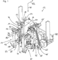
- Figure 1 shows a perspective view of a longitudinal sealing device 12 for a packaging machine.
- the longitudinal sealing device 12 comprises at least one sealing device 10.
- the longitudinal sealing device 12 comprises at least one further sealing device 60.
- the sealing device 10 and the further sealing device 60 are preferably constructed in a mirror-symmetrical manner.
- the sealing device 10 and the further sealing device 60 in particular comprise the same components.
- the components of the further sealing device 60 are only occasionally provided with reference symbols, the reference symbols of the further sealing device 60 having the same numbers as the reference symbols of the sealing device 10, the reference symbols being marked with an apostrophe to distinguish them.
- the sealing device 10 is intended for sealing a packaging material 50.
- the sealing device 10 comprises at least one packaging transport unit 48.
- the packaging transport unit 48 is provided for conveying the packaging material 50 along a transport direction 70 between sealing jaws 16, 20, in particular between the sealing device 10 and the further sealing device 60.
- the transport direction 70 is preferably aligned vertically during operation of the longitudinal sealing device 12 and points in particular from top to bottom.
- the packaging transport unit 48 is designed in particular mirror-symmetrically to a packaging transport unit 48' of the further sealing device 60, which, due to perspective, is in Figure 1 can be seen.
- the packaging transport unit 48 comprises at least one contact conveying element 62 for frictional and/or force-locking with the packaging material 50 (cf. contact conveying element 62' of the further sealing device 60).
- the packaging transport unit 48 comprises at least one guide element 64 (cf. guide element 64' of the further sealing device 60).
- the packaging transport unit 48 comprises at least one further guide element 66 (cf. further guide element 66' of the further sealing device 60).
- the guide elements 64, 66 are provided for guiding the contact conveying element 62 along the transport direction 70.
- the packaging transport unit 48 comprises a gear element 68 for transmitting force and/or torque to the contact conveying element 62 (cf. gear element 68' of the further sealing device 60).
- the gear element 68 is arranged at a distance from the guide element 64 and the further guide element 66 in a direction perpendicular to the transport direction 70.
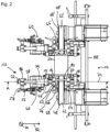
- Figure 2 shows a view of the longitudinal sealing device 12 opposite to the transport direction 70, in particular an underside of the longitudinal sealing device 12.
- the sealing device 10 comprises the sealing jaw 16.
- the sealing device 10 comprises the further sealing jaw 20.
- the sealing device 10 comprises at least one seal holder 14 for fixing the sealing jaw 16.
- the sealing device 10 comprises at least one further seal holder 18 for fixing the further sealing jaw 20.
- the seal holder 14 and the further seal holder 18 are mounted so as to be movable relative to one another.
- the sealing device 10 comprises a mechanical coupling unit 22.
- the seal holder 14 and the further seal holder 18 are arranged on the coupling unit 22.
- the coupling unit 22 comprises at least one force transmission element 24 (cf. Fig.3 ).
- the coupling unit 22 comprises at least one further force transmission element 26, 28, in particular two further force transmission elements 26, 28, one of which is referred to below as an additional force transmission element 28 if a distinction is necessary (cf. Fig.1 and 3 ).
- the force transmission element 24 is provided for transmitting a sealing force provided to the seal holder 14 in the form of a pressure force during sealing.
- the further force transmission elements 26, 28 are provided for transmitting the sealing force provided to the further seal holder 18 in the form of a tensile force during sealing.
- the sealing device 10 comprises at least one, in particular immovable, counter seal holder unit 52.
- the sealing device 10 comprises at least one, in particular immovable, further counter seal holder unit 54.
- the counter seal holder unit 52 forms a pressing surface for pressing on the sealing jaws 16.
- the further counter seal holder unit 54 forms a pressing surface for pressing on the further sealing jaws 20.
- the counter seal holder units 52, 54 comprise in particular a common Counter seal holder element 84, which forms the pressing surfaces of both counter seal holder units 52, 54.
- the counter seal holder unit 52 comprises in particular a counter seal holder and the further counter seal holder unit 54 preferably a further counter seal holder to which the common counter seal holder element 84 is fastened, in particular screwed.
- the contact conveying element 62 is at least partially arranged between the seal holders 14, 18.
- the contact conveying element 62 is arranged between the counter seal holder units 52, 54.
- the counter seal holder units 52, 54 are arranged together with the contact conveying element 62 between the seal holders 14, 18.
- the sealing jaw 16, the further sealing jaw 20 and the contact conveying element 62 are arranged at least substantially flush with respect to a plane perpendicular to the transport direction 70.
- the seal holders 14, 18 are in particular mounted in such a way that they can be displaced relative to one another along a displacement direction 82.
- the seal holder 14, the counter seal holder unit 52, the packaging transport unit 48, the further counter seal holder unit 54 and/or the further seal holder 18, in particular in this order, are arranged on the further force transmission elements 26, 28.
- An axis of rotation of the guide element 64 or of the further guide element 66 runs at least substantially parallel to the displacement direction 82 of the seal holder 14 and/or the further seal holder 18.
- Figure 3 shows a sectional view of the longitudinal sealing device 12 in a sealing plane 72.
- the sealing plane 72 runs in particular perpendicular to the transport direction 70.
- the coupling unit 22 comprises at least one, in particular pneumatic, piston unit 30 with at least one piston chamber 32 and with a piston 34 mounted in the piston chamber 32.
- the piston 34 is operatively connected to the force transmission element 24.
- the piston chamber 32 is operatively connected to the further force transmission elements 26, 28.
- the coupling unit 22 comprises at least one further piston unit 36 with a further piston 38.
- the further piston 38 is arranged along a mechanical chain of action in rows with the piston 34.
- the coupling unit 22 comprises at least one additional piston unit 40 with an additional piston 42.
- the additional piston 42 is arranged parallel to the further piston 38.
- the additional piston unit 40, the piston unit 30 and/or the further piston unit 36 are arranged on a common mounting plate 44 of the piston units 30, 36, 40.
- the sealing device 10 comprises in particular a structural unit as a deflection unit 86.
- the deflection unit 86 is in particular operatively connected to further pistons 38 and/or the additional piston 38.
- the deflection unit 86 is in particular fixed, in particular clamped, to the further force transmission elements 26, 28.
- the coupling unit 22 comprises at least one adjustment element 56, 58, with which a starting position of the seal holder 14 and/or the further seal holder 18 relative to the force transmission element 24 and/or the further force transmission elements 26, 28 and/or relative to the contact conveying element 62 can be adjusted without tools.
- the sealing device 10 comprises a bearing unit 46 for floatingly supporting the coupling unit 22.
- the bearing unit 46 is intended to absorb at least substantially the entire weight of the coupling unit 22 and the seal holder 14, 18.
- the further force transmission element 26, 28 is arranged so as to protrude through a material recess of the seal holder 14.
- the bearing unit 46 comprises a seal holder bearing element 74.
- the seal holder bearing element 74 is designed, for example, as a sliding bearing.
- the seal holder bearing element 74 is arranged in particular in the material recess of the seal holder 14.
- the further force transmission element 26 is mounted in particular in the seal holder bearing element 74.
- the further force transmission element 26, 28 is arranged so as to protrude through a material recess of the packaging transport unit 48.
- the bearing unit 46 comprises a transport bearing element 76.
- the transport bearing element 76 is designed, for example, as a sliding bearing.
- the transport bearing element 76 is arranged, in particular, in the material recess of the packaging transport unit 48.
- the further force transmission element 26 is arranged, in particular, in the transport bearing element 76.
- the further force transmission element 26, 28 is arranged so as to protrude through a material recess of the counter-seal holder unit 52, 54.
- the bearing unit 46 comprises a counter-seal holder bearing element 78.
- the counter-seal holder bearing element 78 is designed, for example, as a sliding bearing.
- the counter-seal holder bearing element 78 is arranged, in particular, in the material recess of the counter-seal holder unit 52.
- the further Force transmission element 26 is mounted in particular in the counter seal holder bearing element 78.
- the bearing unit 46 comprises a further counter seal holder bearing element 80.
- the further counter seal holder bearing element 80 is designed, for example, as a sliding bearing.
- the counter seal holder bearing element 80 is arranged in particular in the material recess of the further counter seal holder unit 54.
- the further force transmission element 26 is mounted in particular in the further counter seal holder bearing element 80.
- the counter seal holder bearing element 78 and/or the further counter seal holder bearing element 80 are arranged in particular within the transport bearing element 76.
- the counter seal holder unit 52 and/or the further counter seal holder unit 54 of the sealing device 10 is arranged, in particular fixed, on the bearing unit 46, in particular on the transport bearing element 76.
- the guide element 64 and/or the further guide element 66 of the packaging transport unit 48 for guiding the contact conveyor element 62 are arranged on the bearing unit 46.
- the guide element 64 is mounted in particular on the transport bearing element 76.
- the sealing jaw 16 is in particular fastened to the seal holder 14.
- the seal holder 14 is preferably fastened to the force transmission element 24.
- the seal holder 14 is in particular movably mounted on the further force transmission elements 26, 28, in particular for carrying out a linear movement.
- the force transmission element 24 is in particular fastened to the piston 34.
- the piston 34 is preferably mounted in the piston chamber 32.
- the piston chamber 32 is preferably fastened to the common mounting plate 44.
- a further piston chamber of the further piston unit 36 and/or an additional piston chamber of the additional piston unit 40 is in particular fastened to the common mounting plate 44.
- the further piston 38 is in particular mounted in the further piston chamber.
- the additional piston 42 is in particular mounted in the additional piston chamber.
- the further piston 38 and/or the additional piston are in particular fastened to the deflection unit 86.
- the further force transmission elements 26, 28 are preferably fastened to the deflection unit 86.
- the further force transmission elements 26, 28 are mounted in particular within the transport bearing element 76.
- the transport bearing element 76 is arranged, in particular fixed, directly or indirectly on a machine frame 88 of the longitudinal seam device 12.
- the further seal holder 20 is attached to the further force transmission elements 18.
- the further sealing jaw 20 is in particular attached to the further seal holder 20.
- the seal holders 16, 20 move in opposite directions perpendicular to the transport direction 70 via the force transmission elements 24, 26, 28 and in particular via the deflection unit 86.
- a maximum longitudinal extension of the contact conveying element 62 parallel to the transport direction 70 and a maximum longitudinal extension of the seal holder 14 and/or the further seal holder 18 parallel to the transport direction 70 are at least substantially the same length.
- a longitudinal axis of a mounting rod of the sealing device 10, on which the seal holder 14 and/or the further seal holder 18 are arranged, and an axis of rotation of the guide element 64 or the further guide element 66 are arranged at least substantially coaxially.
- the mounting rod is formed in particular by the further force transmission element 26.
Landscapes
- Engineering & Computer Science (AREA)
- Mechanical Engineering (AREA)
- Auxiliary Devices For And Details Of Packaging Control (AREA)
Claims (8)
- Dispositif de scellement pour un appareil de scellement longitudinal d'une machine d'emballage,avec au moins une mâchoire de scellement (16) et au moins une mâchoire de scellement supplémentaire (20) pour le scellement d'un matériau d'emballage (50),avec au moins un support de scellage (14) pour fixer la mâchoire de scellement (16) et un support de scellage supplémentaire (18) pour fixer la mâchoire de scellement supplémentaire (20), le support de scellage (14) et le support de scellage supplémentaire (18) étant supportés de manière mobile l'un par rapport à l'autre,et avec au moins une unité de transport d'emballage (48) pour le transport d'un matériau d'emballage (50) le long d'une direction de transport (70) entre et à travers les mâchoires de scellement (16, 20),l'unité de transport d'emballage (48) comprenant au moins un élément-contact de transport (62) pour une liaison par friction et/ou par force avec le matériau d'emballage (50), l'élément-contact de transport (62) étant disposé au moins en partie entre les supports de scellage (14, 18),avec une barre de montage sur laquelle sont disposés le support de scellement (14) et/ou le support de scellement supplémentaire (18),l'unité de transport d'emballage (48) comprenant un élément de guidage (64) et un élément de guidage supplémentaire (66) pour un guidage de l'élément-contact de transport (62) le long de la direction de transport (70), caractérisé en ce qu'un axe longitudinal de la barre de montage et un axe rotatif de l'élément de guidage (64) ou de l'élément de guidage supplémentaire (66) sont disposés au moins sensiblement coaxialement.
- Dispositif de scellement selon la revendication 1,caractérisé par au moins une unité de support de contre-scellement (52, 54) qui forme une surface de pression pour presser l'une des mâchoires de scellement (16, 20) sur ladite surface de pression,et par une unité de palier (46) sur laquelle sont disposés l'au moins une unité de support de contre-scellement (52, 54) et un élément de guidage (64, 66) de l'unité de transport d'emballage (48) pour un guidage de l'élément-contact de transport (62).
- Dispositif de scellement selon la revendication 1 ou 2,
caractérisé en ce qu'une étendue longitudinale maximale de l'élément-contact de transport (62), qui est parallèle à la direction de transport (70), et une étendue longitudinale maximale du support de scellement (14) et/ou du support de scellement supplémentaire (18), qui est parallèle à la direction de transport (70), sont réalisées au moins sensiblement de même longueur. - Dispositif de scellement selon l'une des revendications précédentes,caractérisé en ce que l'unité de transport d'emballage (48) comprend au moins l'élément de guidage (64) et l'élément de guidage supplémentaire (66) pour un guidage de l'élément-contact de transport (62) le long de la direction de transport (70)et comprend un élément de transmission (68) disposé à l'écart de l'élément de guidage (64) et de l'élément de guidage supplémentaire (66) en direction perpendiculaire à la direction de transport (70) pour une transmission de force et/ou de couple à l'élément-contact de transport (62).
- Dispositif de scellement selon l'une des revendications précédentes, caractérisé en ce que l'unité de transport d'emballage (48) comprend l'élément de guidage (64) et l'élément de guidage supplémentaire (66) pour un guidage de l'élément-contact de transport (62) le long de la direction de transport (70),
où l'axe rotatif de l'élément de guidage (64) ou de l'élément de guidage supplémentaire (66) s'étend au moins sensiblement en parallèle à une direction de déplacement du support de scellement (14) et/ou du support de scellement supplémentaire (18). - Dispositif de scellement selon l'une des revendications précédentes, caractérisé en ce que la mâchoire de scellage (16), la mâchoire de scellage supplémentaire (20) et l'élément-contact de transport (62) sont disposés au moins sensiblement à fleur par rapport à un plan perpendiculaire à la direction de transport (70).
- Dispositif de scellement selon l'une des revendications précédentes, caractérisé par au moins un élément de réglage (56, 58) moyennant lequel une position initiale du support de scellement (14) et/ou du support de scellement supplémentaire (18) peut être réglée sans outil par rapport à l'élément-contact de transport (62).
- Appareil de scellement longitudinal avec au moins un dispositif de scellement selon l'une des revendications précédentes et avec au moins un dispositif de scellement supplémentaire selon l'une des revendications précédentes.
Applications Claiming Priority (1)
| Application Number | Priority Date | Filing Date | Title |
|---|---|---|---|
| DE102021125154.0A DE102021125154A1 (de) | 2021-09-28 | 2021-09-28 | Siegelvorrichtung und Längssiegelvorrichtung mit einer solchen Siegelvorrichtung |
Publications (2)
| Publication Number | Publication Date |
|---|---|
| EP4159628A1 EP4159628A1 (fr) | 2023-04-05 |
| EP4159628B1 true EP4159628B1 (fr) | 2024-08-28 |
Family
ID=83506702
Family Applications (1)
| Application Number | Title | Priority Date | Filing Date |
|---|---|---|---|
| EP22198078.2A Active EP4159628B1 (fr) | 2021-09-28 | 2022-09-27 | Dispositif de scellement et dispositif de scellement longitudinal doté d'un tel dispositif de scellement |
Country Status (2)
| Country | Link |
|---|---|
| EP (1) | EP4159628B1 (fr) |
| DE (1) | DE102021125154A1 (fr) |
Family Cites Families (4)
| Publication number | Priority date | Publication date | Assignee | Title |
|---|---|---|---|---|
| EP1167192A3 (fr) | 2000-06-30 | 2004-02-04 | O-Mega Packaging AG | Dispositif pour sceller les arêtes de sacs tenant debout dans une machine de fabrication de sacs tubulaires |
| JP4447882B2 (ja) * | 2003-10-17 | 2010-04-07 | 株式会社東京自働機械製作所 | 筋目付け機構を備えた製袋装置 |
| JPWO2007142114A1 (ja) | 2006-06-02 | 2009-10-22 | 株式会社イシダ | 包装装置 |
| DE102006046123B4 (de) | 2006-09-28 | 2019-04-04 | Rovema Gmbh | Schlauchbeutelmaschine |
-
2021
- 2021-09-28 DE DE102021125154.0A patent/DE102021125154A1/de active Pending
-
2022
- 2022-09-27 EP EP22198078.2A patent/EP4159628B1/fr active Active
Also Published As
| Publication number | Publication date |
|---|---|
| EP4159628A1 (fr) | 2023-04-05 |
| DE102021125154A1 (de) | 2023-03-30 |
Similar Documents
| Publication | Publication Date | Title |
|---|---|---|
| EP0086364B1 (fr) | Appareil pour sceller un emballage de fluides | |
| EP3678940B1 (fr) | Station de travail à mécanisme de course pour une machine d'emballage | |
| CH427622A (de) | Verfahren und Vorrichtung zur Herstellung von mit fliessfähigem Füllgut gefüllten Quaderpackungen | |
| DE102015102860A1 (de) | Vorrichtung und Verfahren zum Verpressen von Packungsmänteln | |
| DE4307142C1 (de) | Vorrichtung zum Greifen von Flächengebilden, insbesondere von erhitzten, biegeschlaffen, fasverstärkten Kunststoffmaterialzuschnitten | |
| DE1552017B2 (de) | Zwei-Walzenrundbiegemaschine | |
| EP0621187A1 (fr) | Machine de fabrication de sachets plats disposée verticalement et à opération intermittente | |
| DE602005006314T2 (de) | Schweisswerkzeug für eine umreifungsvorrichtung | |
| DE19757577C2 (de) | Verfahren und Vorrichtung zum Formen einer Bahn | |
| DE2423885C2 (de) | Vorrichtung zum Übergeben von Stapeln aus blattförmigen Materialzuschnitten | |
| EP4159628B1 (fr) | Dispositif de scellement et dispositif de scellement longitudinal doté d'un tel dispositif de scellement | |
| EP2156743B1 (fr) | Rail de guidage | |
| EP4408647B1 (fr) | Dispositif de scellement et dispositif de scellement longitudinal pourvu d'un tel dispositif de scellement | |
| DE69508535T2 (de) | Nockenvorrichtung | |
| EP0044395B1 (fr) | Dispositif pour fabriquer continuellement des emballages remplis de forme prismatique | |
| EP0545047B1 (fr) | Machine pour souder le joint de scellage d'un emballage | |
| EP0567769B1 (fr) | Dispositif pour replier le fond d'un carton d'emballage | |
| AT406252B (de) | Vorrichtung zum füllen und verschliessen von offenen säcken | |
| DE2928847C2 (de) | Vorrichtung zum Bearbeiten eines Schlauches aus Verpackungsmaterial | |
| DE69508042T2 (de) | Einrichtung zur Senkung von Drehmomentschwankungen in Antriebsgeräten | |
| DE2950553C2 (de) | Maschine zum Herstellen und Füllen von Säcken | |
| DE202008013097U1 (de) | Rotierende Füllmaschine | |
| DE69725928T2 (de) | Quersiegelvorrichtung für eine Verpackungsmaschine | |
| EP0049829A2 (fr) | Machine pour la fabrication d'emballages du type sachet à deux compartiments | |
| DE973238C (de) | Verfahren und Vorrichtung zum Zerlegen eines fluessigkeitsgefuellten Behaelters aus thermoplastischem Kunststoff |
Legal Events
| Date | Code | Title | Description |
|---|---|---|---|
| PUAI | Public reference made under article 153(3) epc to a published international application that has entered the european phase |
Free format text: ORIGINAL CODE: 0009012 |
|
| STAA | Information on the status of an ep patent application or granted ep patent |
Free format text: STATUS: THE APPLICATION HAS BEEN PUBLISHED |
|
| AK | Designated contracting states |
Kind code of ref document: A1 Designated state(s): AL AT BE BG CH CY CZ DE DK EE ES FI FR GB GR HR HU IE IS IT LI LT LU LV MC MK MT NL NO PL PT RO RS SE SI SK SM TR |
|
| STAA | Information on the status of an ep patent application or granted ep patent |
Free format text: STATUS: REQUEST FOR EXAMINATION WAS MADE |
|
| 17P | Request for examination filed |
Effective date: 20230927 |
|
| RBV | Designated contracting states (corrected) |
Designated state(s): AL AT BE BG CH CY CZ DE DK EE ES FI FR GB GR HR HU IE IS IT LI LT LU LV MC MK MT NL NO PL PT RO RS SE SI SK SM TR |
|
| RIC1 | Information provided on ipc code assigned before grant |
Ipc: B65B 51/26 20060101ALI20240213BHEP Ipc: B65B 9/213 20120101ALI20240213BHEP Ipc: B65B 9/207 20120101ALI20240213BHEP Ipc: B65B 9/20 20120101AFI20240213BHEP |
|
| GRAP | Despatch of communication of intention to grant a patent |
Free format text: ORIGINAL CODE: EPIDOSNIGR1 |
|
| STAA | Information on the status of an ep patent application or granted ep patent |
Free format text: STATUS: GRANT OF PATENT IS INTENDED |
|
| INTG | Intention to grant announced |
Effective date: 20240322 |
|
| GRAS | Grant fee paid |
Free format text: ORIGINAL CODE: EPIDOSNIGR3 |
|
| GRAA | (expected) grant |
Free format text: ORIGINAL CODE: 0009210 |
|
| STAA | Information on the status of an ep patent application or granted ep patent |
Free format text: STATUS: THE PATENT HAS BEEN GRANTED |
|
| AK | Designated contracting states |
Kind code of ref document: B1 Designated state(s): AL AT BE BG CH CY CZ DE DK EE ES FI FR GB GR HR HU IE IS IT LI LT LU LV MC MK MT NL NO PL PT RO RS SE SI SK SM TR |
|
| REG | Reference to a national code |
Ref country code: CH Ref legal event code: EP |
|
| REG | Reference to a national code |
Ref country code: DE Ref legal event code: R096 Ref document number: 502022001563 Country of ref document: DE |
|
| REG | Reference to a national code |
Ref country code: IE Ref legal event code: FG4D Free format text: LANGUAGE OF EP DOCUMENT: GERMAN |
|
| REG | Reference to a national code |
Ref country code: LT Ref legal event code: MG9D |
|
| PG25 | Lapsed in a contracting state [announced via postgrant information from national office to epo] |
Ref country code: NO Free format text: LAPSE BECAUSE OF FAILURE TO SUBMIT A TRANSLATION OF THE DESCRIPTION OR TO PAY THE FEE WITHIN THE PRESCRIBED TIME-LIMIT Effective date: 20241128 |
|
| PG25 | Lapsed in a contracting state [announced via postgrant information from national office to epo] |
Ref country code: NL Free format text: LAPSE BECAUSE OF FAILURE TO SUBMIT A TRANSLATION OF THE DESCRIPTION OR TO PAY THE FEE WITHIN THE PRESCRIBED TIME-LIMIT Effective date: 20240828 Ref country code: PL Free format text: LAPSE BECAUSE OF FAILURE TO SUBMIT A TRANSLATION OF THE DESCRIPTION OR TO PAY THE FEE WITHIN THE PRESCRIBED TIME-LIMIT Effective date: 20240828 Ref country code: GR Free format text: LAPSE BECAUSE OF FAILURE TO SUBMIT A TRANSLATION OF THE DESCRIPTION OR TO PAY THE FEE WITHIN THE PRESCRIBED TIME-LIMIT Effective date: 20241129 Ref country code: PT Free format text: LAPSE BECAUSE OF FAILURE TO SUBMIT A TRANSLATION OF THE DESCRIPTION OR TO PAY THE FEE WITHIN THE PRESCRIBED TIME-LIMIT Effective date: 20241230 Ref country code: FI Free format text: LAPSE BECAUSE OF FAILURE TO SUBMIT A TRANSLATION OF THE DESCRIPTION OR TO PAY THE FEE WITHIN THE PRESCRIBED TIME-LIMIT Effective date: 20240828 |
|
| PG25 | Lapsed in a contracting state [announced via postgrant information from national office to epo] |
Ref country code: BG Free format text: LAPSE BECAUSE OF FAILURE TO SUBMIT A TRANSLATION OF THE DESCRIPTION OR TO PAY THE FEE WITHIN THE PRESCRIBED TIME-LIMIT Effective date: 20240828 |
|
| PG25 | Lapsed in a contracting state [announced via postgrant information from national office to epo] |
Ref country code: LV Free format text: LAPSE BECAUSE OF FAILURE TO SUBMIT A TRANSLATION OF THE DESCRIPTION OR TO PAY THE FEE WITHIN THE PRESCRIBED TIME-LIMIT Effective date: 20240828 |
|
| REG | Reference to a national code |
Ref country code: NL Ref legal event code: MP Effective date: 20240828 |
|
| PG25 | Lapsed in a contracting state [announced via postgrant information from national office to epo] |
Ref country code: IS Free format text: LAPSE BECAUSE OF FAILURE TO SUBMIT A TRANSLATION OF THE DESCRIPTION OR TO PAY THE FEE WITHIN THE PRESCRIBED TIME-LIMIT Effective date: 20241228 |
|
| PG25 | Lapsed in a contracting state [announced via postgrant information from national office to epo] |
Ref country code: HR Free format text: LAPSE BECAUSE OF FAILURE TO SUBMIT A TRANSLATION OF THE DESCRIPTION OR TO PAY THE FEE WITHIN THE PRESCRIBED TIME-LIMIT Effective date: 20240828 |
|
| PG25 | Lapsed in a contracting state [announced via postgrant information from national office to epo] |
Ref country code: RS Free format text: LAPSE BECAUSE OF FAILURE TO SUBMIT A TRANSLATION OF THE DESCRIPTION OR TO PAY THE FEE WITHIN THE PRESCRIBED TIME-LIMIT Effective date: 20241128 Ref country code: ES Free format text: LAPSE BECAUSE OF FAILURE TO SUBMIT A TRANSLATION OF THE DESCRIPTION OR TO PAY THE FEE WITHIN THE PRESCRIBED TIME-LIMIT Effective date: 20240828 |
|
| PG25 | Lapsed in a contracting state [announced via postgrant information from national office to epo] |
Ref country code: RS Free format text: LAPSE BECAUSE OF FAILURE TO SUBMIT A TRANSLATION OF THE DESCRIPTION OR TO PAY THE FEE WITHIN THE PRESCRIBED TIME-LIMIT Effective date: 20241128 Ref country code: PT Free format text: LAPSE BECAUSE OF FAILURE TO SUBMIT A TRANSLATION OF THE DESCRIPTION OR TO PAY THE FEE WITHIN THE PRESCRIBED TIME-LIMIT Effective date: 20241230 Ref country code: PL Free format text: LAPSE BECAUSE OF FAILURE TO SUBMIT A TRANSLATION OF THE DESCRIPTION OR TO PAY THE FEE WITHIN THE PRESCRIBED TIME-LIMIT Effective date: 20240828 Ref country code: NO Free format text: LAPSE BECAUSE OF FAILURE TO SUBMIT A TRANSLATION OF THE DESCRIPTION OR TO PAY THE FEE WITHIN THE PRESCRIBED TIME-LIMIT Effective date: 20241128 Ref country code: NL Free format text: LAPSE BECAUSE OF FAILURE TO SUBMIT A TRANSLATION OF THE DESCRIPTION OR TO PAY THE FEE WITHIN THE PRESCRIBED TIME-LIMIT Effective date: 20240828 Ref country code: LV Free format text: LAPSE BECAUSE OF FAILURE TO SUBMIT A TRANSLATION OF THE DESCRIPTION OR TO PAY THE FEE WITHIN THE PRESCRIBED TIME-LIMIT Effective date: 20240828 Ref country code: IS Free format text: LAPSE BECAUSE OF FAILURE TO SUBMIT A TRANSLATION OF THE DESCRIPTION OR TO PAY THE FEE WITHIN THE PRESCRIBED TIME-LIMIT Effective date: 20241228 Ref country code: HR Free format text: LAPSE BECAUSE OF FAILURE TO SUBMIT A TRANSLATION OF THE DESCRIPTION OR TO PAY THE FEE WITHIN THE PRESCRIBED TIME-LIMIT Effective date: 20240828 Ref country code: GR Free format text: LAPSE BECAUSE OF FAILURE TO SUBMIT A TRANSLATION OF THE DESCRIPTION OR TO PAY THE FEE WITHIN THE PRESCRIBED TIME-LIMIT Effective date: 20241129 Ref country code: FI Free format text: LAPSE BECAUSE OF FAILURE TO SUBMIT A TRANSLATION OF THE DESCRIPTION OR TO PAY THE FEE WITHIN THE PRESCRIBED TIME-LIMIT Effective date: 20240828 Ref country code: ES Free format text: LAPSE BECAUSE OF FAILURE TO SUBMIT A TRANSLATION OF THE DESCRIPTION OR TO PAY THE FEE WITHIN THE PRESCRIBED TIME-LIMIT Effective date: 20240828 Ref country code: BG Free format text: LAPSE BECAUSE OF FAILURE TO SUBMIT A TRANSLATION OF THE DESCRIPTION OR TO PAY THE FEE WITHIN THE PRESCRIBED TIME-LIMIT Effective date: 20240828 |
|
| PG25 | Lapsed in a contracting state [announced via postgrant information from national office to epo] |
Ref country code: RO Free format text: LAPSE BECAUSE OF FAILURE TO SUBMIT A TRANSLATION OF THE DESCRIPTION OR TO PAY THE FEE WITHIN THE PRESCRIBED TIME-LIMIT Effective date: 20240828 Ref country code: DK Free format text: LAPSE BECAUSE OF FAILURE TO SUBMIT A TRANSLATION OF THE DESCRIPTION OR TO PAY THE FEE WITHIN THE PRESCRIBED TIME-LIMIT Effective date: 20240828 Ref country code: SM Free format text: LAPSE BECAUSE OF FAILURE TO SUBMIT A TRANSLATION OF THE DESCRIPTION OR TO PAY THE FEE WITHIN THE PRESCRIBED TIME-LIMIT Effective date: 20240828 |
|
| PG25 | Lapsed in a contracting state [announced via postgrant information from national office to epo] |
Ref country code: EE Free format text: LAPSE BECAUSE OF FAILURE TO SUBMIT A TRANSLATION OF THE DESCRIPTION OR TO PAY THE FEE WITHIN THE PRESCRIBED TIME-LIMIT Effective date: 20240828 |
|
| PG25 | Lapsed in a contracting state [announced via postgrant information from national office to epo] |
Ref country code: CZ Free format text: LAPSE BECAUSE OF FAILURE TO SUBMIT A TRANSLATION OF THE DESCRIPTION OR TO PAY THE FEE WITHIN THE PRESCRIBED TIME-LIMIT Effective date: 20240828 |
|
| PG25 | Lapsed in a contracting state [announced via postgrant information from national office to epo] |
Ref country code: SK Free format text: LAPSE BECAUSE OF FAILURE TO SUBMIT A TRANSLATION OF THE DESCRIPTION OR TO PAY THE FEE WITHIN THE PRESCRIBED TIME-LIMIT Effective date: 20240828 |
|
| PG25 | Lapsed in a contracting state [announced via postgrant information from national office to epo] |
Ref country code: LU Free format text: LAPSE BECAUSE OF NON-PAYMENT OF DUE FEES Effective date: 20240927 |
|
| REG | Reference to a national code |
Ref country code: DE Ref legal event code: R097 Ref document number: 502022001563 Country of ref document: DE |
|
| PLBE | No opposition filed within time limit |
Free format text: ORIGINAL CODE: 0009261 |
|
| STAA | Information on the status of an ep patent application or granted ep patent |
Free format text: STATUS: NO OPPOSITION FILED WITHIN TIME LIMIT |
|
| PG25 | Lapsed in a contracting state [announced via postgrant information from national office to epo] |
Ref country code: MC Free format text: LAPSE BECAUSE OF FAILURE TO SUBMIT A TRANSLATION OF THE DESCRIPTION OR TO PAY THE FEE WITHIN THE PRESCRIBED TIME-LIMIT Effective date: 20240828 |
|
| REG | Reference to a national code |
Ref country code: BE Ref legal event code: MM Effective date: 20240930 |
|
| PG25 | Lapsed in a contracting state [announced via postgrant information from national office to epo] |
Ref country code: BE Free format text: LAPSE BECAUSE OF NON-PAYMENT OF DUE FEES Effective date: 20240930 |
|
| PG25 | Lapsed in a contracting state [announced via postgrant information from national office to epo] |
Ref country code: IE Free format text: LAPSE BECAUSE OF NON-PAYMENT OF DUE FEES Effective date: 20240927 |
|
| 26N | No opposition filed |
Effective date: 20250530 |
|
| PG25 | Lapsed in a contracting state [announced via postgrant information from national office to epo] |
Ref country code: SE Free format text: LAPSE BECAUSE OF FAILURE TO SUBMIT A TRANSLATION OF THE DESCRIPTION OR TO PAY THE FEE WITHIN THE PRESCRIBED TIME-LIMIT Effective date: 20240828 |
|
| REG | Reference to a national code |
Ref country code: CH Ref legal event code: U11 Free format text: ST27 STATUS EVENT CODE: U-0-0-U10-U11 (AS PROVIDED BY THE NATIONAL OFFICE) Effective date: 20251001 |
|
| PGFP | Annual fee paid to national office [announced via postgrant information from national office to epo] |
Ref country code: DE Payment date: 20250919 Year of fee payment: 4 |
|
| PGFP | Annual fee paid to national office [announced via postgrant information from national office to epo] |
Ref country code: AT Payment date: 20251020 Year of fee payment: 4 Ref country code: FR Payment date: 20250926 Year of fee payment: 4 |
|
| PGFP | Annual fee paid to national office [announced via postgrant information from national office to epo] |
Ref country code: IT Payment date: 20250930 Year of fee payment: 4 |
|
| PGFP | Annual fee paid to national office [announced via postgrant information from national office to epo] |
Ref country code: CH Payment date: 20251001 Year of fee payment: 4 |
|
| PG25 | Lapsed in a contracting state [announced via postgrant information from national office to epo] |
Ref country code: CY Free format text: LAPSE BECAUSE OF FAILURE TO SUBMIT A TRANSLATION OF THE DESCRIPTION OR TO PAY THE FEE WITHIN THE PRESCRIBED TIME-LIMIT; INVALID AB INITIO Effective date: 20220927 |
|
| PG25 | Lapsed in a contracting state [announced via postgrant information from national office to epo] |
Ref country code: HU Free format text: LAPSE BECAUSE OF FAILURE TO SUBMIT A TRANSLATION OF THE DESCRIPTION OR TO PAY THE FEE WITHIN THE PRESCRIBED TIME-LIMIT; INVALID AB INITIO Effective date: 20220927 |
|
| REG | Reference to a national code |
Ref country code: DE Ref legal event code: R081 Ref document number: 502022001563 Country of ref document: DE Owner name: HESSER PACKAGING GMBH, DE Free format text: FORMER OWNER: SYNTEGON TECHNOLOGY GMBH, 71332 WAIBLINGEN, DE |