EP4159665A1 - Système de dosage d'un produit aromatique dans des conteneurs - Google Patents
Système de dosage d'un produit aromatique dans des conteneurs Download PDFInfo
- Publication number
- EP4159665A1 EP4159665A1 EP21200659.7A EP21200659A EP4159665A1 EP 4159665 A1 EP4159665 A1 EP 4159665A1 EP 21200659 A EP21200659 A EP 21200659A EP 4159665 A1 EP4159665 A1 EP 4159665A1
- Authority
- EP
- European Patent Office
- Prior art keywords
- valve
- duct
- aromatic product
- tank
- recirculation
- Prior art date
- Legal status (The legal status is an assumption and is not a legal conclusion. Google has not performed a legal analysis and makes no representation as to the accuracy of the status listed.)
- Withdrawn
Links
- 125000003118 aryl group Chemical group 0.000 title claims abstract description 156
- 238000004519 manufacturing process Methods 0.000 claims abstract description 18
- 238000011144 upstream manufacturing Methods 0.000 claims abstract description 16
- 238000005086 pumping Methods 0.000 claims abstract description 12
- 238000001816 cooling Methods 0.000 claims abstract description 11
- 239000002826 coolant Substances 0.000 claims abstract description 4
- 239000012530 fluid Substances 0.000 claims description 35
- 239000000203 mixture Substances 0.000 claims description 29
- 238000007599 discharging Methods 0.000 claims description 5
- 238000011010 flushing procedure Methods 0.000 claims description 5
- 230000003134 recirculating effect Effects 0.000 claims description 4
- 230000004913 activation Effects 0.000 claims description 2
- 230000001276 controlling effect Effects 0.000 description 23
- 235000013305 food Nutrition 0.000 description 9
- 238000000034 method Methods 0.000 description 8
- XLYOFNOQVPJJNP-UHFFFAOYSA-N water Substances O XLYOFNOQVPJJNP-UHFFFAOYSA-N 0.000 description 4
- IJGRMHOSHXDMSA-UHFFFAOYSA-N Atomic nitrogen Chemical compound N#N IJGRMHOSHXDMSA-UHFFFAOYSA-N 0.000 description 2
- 241001122767 Theaceae Species 0.000 description 2
- 238000002485 combustion reaction Methods 0.000 description 2
- 239000003599 detergent Substances 0.000 description 2
- 235000013399 edible fruits Nutrition 0.000 description 2
- 239000007789 gas Substances 0.000 description 2
- 239000007788 liquid Substances 0.000 description 2
- 239000000344 soap Substances 0.000 description 2
- 235000021028 berry Nutrition 0.000 description 1
- 235000020971 citrus fruits Nutrition 0.000 description 1
- 239000000796 flavoring agent Substances 0.000 description 1
- 235000019634 flavors Nutrition 0.000 description 1
- 239000003205 fragrance Substances 0.000 description 1
- 239000011521 glass Substances 0.000 description 1
- 239000011261 inert gas Substances 0.000 description 1
- 229910052757 nitrogen Inorganic materials 0.000 description 1
- 239000002304 perfume Substances 0.000 description 1
- 230000001105 regulatory effect Effects 0.000 description 1
Images



Classifications
-
- B—PERFORMING OPERATIONS; TRANSPORTING
- B67—OPENING, CLOSING OR CLEANING BOTTLES, JARS OR SIMILAR CONTAINERS; LIQUID HANDLING
- B67C—CLEANING, FILLING WITH LIQUIDS OR SEMILIQUIDS, OR EMPTYING, OF BOTTLES, JARS, CANS, CASKS, BARRELS, OR SIMILAR CONTAINERS, NOT OTHERWISE PROVIDED FOR; FUNNELS
- B67C3/00—Bottling liquids or semiliquids; Filling jars or cans with liquids or semiliquids using bottling or like apparatus; Filling casks or barrels with liquids or semiliquids
- B67C3/02—Bottling liquids or semiliquids; Filling jars or cans with liquids or semiliquids using bottling or like apparatus
Definitions
- the present invention relates to a system for dosing an aromatic product, preferably an aromatic food product, into containers adapted to contain a pourable product, preferably a pourable food product.
- Filling machines are known, which are used to fill containers, such as bottles, jars, cans or the like, with a pourable product.
- Such machines essentially comprise a carousel rotatable about a vertical axis, a reservoir for containing the pourable product, and a plurality of filling valves.
- the filling valves are peripherally carried by the carousel, are connected to the reservoir by respective ducts and are advanced by the carousel along a substantially arc-shaped filling path.
- the above-mentioned filling machines further comprise an inlet device, such as an inlet star wheel configured to sequentially feed empty containers to the carousel, and an outlet device, such as an outlet star wheel, configured to receive the filled containers from the carousel.
- an inlet device such as an inlet star wheel configured to sequentially feed empty containers to the carousel
- an outlet device such as an outlet star wheel, configured to receive the filled containers from the carousel.
- the carousel comprises a plurality of support members, each apt to receive and hold in vertical position, below the respective filling valve, one container to be filled at a time.
- Each filling valve is configured to feed a predetermined amount of pourable product to the relative container while the filling valve is advanced along the filling path due to the rotary motion imparted thereto by the carousel.
- a typical filling valve comprises a tubular body, a shutter movably engaging the tubular body, and an actuator to control the movement of the shutter.
- Such valves are well-known and they will not be described in detail herein.
- the pourable product fed to the containers is a food product, for example still or sparkling water, tea, or the like; in this case the aromatic product is also a food product, for example a fruit essence (such as citrus fruits, berries or the like) .
- the pourable product fed to the containers is a non-food product, for example soaps, detergents, room fragrances, or the like; in this case the aromatic product does not need to be a food product.
- the known filling machines comprise a system for dosing the aromatic product into the previously filled containers.
- the dosing system is typically arranged at a dosing station operatively downstream of the carousel, for example at the outlet star wheel.
- Such dosing system normally comprises a feeding circuit for supplying the aromatic product and at least one dosing valve hydraulically connected to the feeding circuit and configured to sequentially dose a predetermined quantity of aromatic product into each container when this latter transits at the dosing station.
- the dosing valve comprises an inlet receiving the aromatic product from the feeding circuit, an outlet for sequentially feeding the aromatic product to each container, a shutter interposed between the inlet and the outlet and an actuator to control a reciprocating motion of the shutter between an open position and a closed position.
- the dosing valve is typically fixed relative to the outlet star wheel, unlike the filling valves which are carried in rotation by the carousel to fill the respective containers placed under them. Therefore, the containers are to be dosed in a short time span corresponding to their transit below the dosing valve.
- number 1 indicates as a whole a filling machine configured to fill a plurality of containers 2 with a pourable product, preferably a pourable food product.
- the pourable product (for example still water, sparkling water, tea or the like) is of the type suitable for being diluted with an aromatic product, preferably an aromatic food product, for example a fruit essence or the like.
- the aromatic product can be a flavor.
- the present invention is equally applicable in the case in which the pourable product is of a non-food type (for example soap, detergent, perfume for environments, or the like) and destined to be diluted with the aromatic product.
- a non-food type for example soap, detergent, perfume for environments, or the like
- the containers 2 are defined by bottles, jars or flasks, made of plastic or glass, or by cans.
- the filling machine 1 essentially comprises:
- each filling valve 4 is configured to selectively feed a predetermined quantity of pourable product to one container 2 at a time, while the same container 2 is conveyed along the filling path due to the rotary motion imparted thereto by the carousel 3.
- each filling valve 4 is carried peripherally by the carousel 3 and is hydraulically connected to the tank by means of a respective duct 5 of the filling machine 1.
- the filling machine 1 also comprises an inlet conveyor, preferably a star wheel 6 adapted to feed a succession of empty containers 2 to the carousel 3, and an outlet conveyor, preferably a star wheel 7, adapted to receive the containers 2 filled by the carousel 3.
- an inlet conveyor preferably a star wheel 6 adapted to feed a succession of empty containers 2 to the carousel 3
- an outlet conveyor preferably a star wheel 7, adapted to receive the containers 2 filled by the carousel 3.
- the star wheels 6 and 7 rotate around respective axes A' and A" which are substantially parallel to the axis A of the carousel 3.
- the axes A, A' and A" are vertical.
- the filling machine 1 is further configured to feed a dose of aromatic product inside the containers 2, preferably into the containers 2 previously filled with the pourable product.
- the filling machine 1 further comprises a dosing system 8 (schematically illustrated in Figure 1 ), which is operatively arranged downstream of the carousel 3.
- a dosing system 8 (schematically illustrated in Figure 1 ), which is operatively arranged downstream of the carousel 3.
- the dosing system 8 is arranged at the output star wheel 7 to feed the aromatic product to the filled containers 2 that transit on the latter.
- the filling machine 1 is configured for feeding the dose of aromatic product inside the containers 2 which are still to be filled with the pourable product.
- the dosing system 8 is arranged operatively upstream of carousel 3, for example at the inlet star wheel 6.
- dosing system 8 comprises at least one dosing valve 10.
- the dosing valve 10 is hydraulically connected to a hydraulic circuit 11.
- the hydraulic circuit is configured for supplying the aromatic product to the dosing valve 10.
- the dosing valve 10 is configured for dosing (feed) a predetermined quantity of aromatic product inside each container 2, when this latter transits through a dosing station D.
- valve 10 is fixed with respect to the star wheel 7, with the aromatic product being dosed in each container 2 in the time interval corresponding to the transit of the container 2 below the valve 10 itself, at the dosing station D.
- the dosing station D is arranged at the outlet star wheel 7.
- the valve 10 is of the known type and comprises a tubular body, a shutter movably engaging the tubular body and an actuator to control the motion of the shutter.
- Dosing system 8 further comprises a cooling duct 12 for supplying a cooling medium, such as (preferably cooled) water or air or Freon ® .
- a cooling medium such as (preferably cooled) water or air or Freon ® .
- cooling duct 12 is configured for supplying, i.e. for circulating, the cooling medium in the vicinity of hydraulic circuit 11, as better explained below.
- Hydraulic circuit 11 comprises:
- hydraulic circuit 11 further comprises:
- the recirculation duct 17 comprises:
- the temperature of the aromatic product can be maintained low, i.e. at a temperature value below a certain predetermined threshold.
- the dosing system 8 comprises a control unit 21.
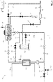
- the control unit 21 is configured for controlling the pump 18, the tank valve 20, the inlet recirculation valve 19 and the dosing valve 10, to define a production mode of the dosing system 8 in which, by means of the control unit 21:
- FIG. 2 The above-mentioned production mode is schematically depicted in Figure 2 , in which the open valves are depicted as empty white, the closed valves are depicted as full black and the selectively activatable valves (such as the tank valve 20 and the dosing valve 10) are depicted in mixed black and white.
- the aromatic product can be cooled during production, thereby avoiding undesired and dangerous combustion of the aromatic product. Hence, the safety problems related to the aromatic product being flammable can be avoided, resulting in an improvement of the overall safety of the dosing operation.
- the tank 13 is pressurized by a pressurization gas (known per se and not shown), for example air or an inert gas, such as nitrogen.
- a pressurization gas for example air or an inert gas, such as nitrogen.
- control unit 21 is configured for controlling the activation of the tank valve 20, based on the level of the aromatic product inside the tank 13 and/or based on the pressure of the pressurization gas inside the tank 13.
- the hydraulic circuit 11 further comprises:
- outlet recirculation valve 22 and the non-return valve 23 are arranged along the third portion 17c.
- the outlet recirculation valve 22 is configured for regulating the pressure of the aromatic product exiting the recirculation duct 17.
- the product coming from the recirculation duct 17 has been pressurized and is at a pressure greater than the pressure of the input duct 14. Therefore, there is a risk that the product coming from the recirculation duct 17 through the second branching 15b, pushes out the product coming from the input duct 14. Therefore the outlet recirculation valve 22 helps in allowing recirculation of the aromatic product.
- the hydraulic circuit 11 may comprise only one of the outlet recirculation valve 22 and the non-return valve 23.
- dosing system 8 comprises an input valve 24, which is arranged at the input duct 14, for selectively allowing the supply of aromatic product into the hydraulic circuit 11.
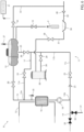
- control unit 21 is further configured for controlling the input valve 24 (i.e. for controlling the aforementioned components and additionally the input valve 24), to define a first recirculation mode of the dosing system 8 according to which, by means of the control unit 21:
- Such first recirculation mode is schematically depicted in Figure 3 .
- the above configuration is particularly advantageous when the production mode is stopped, for example voluntarily by the user due to a format change or to the need for resupplying containers 2, or the like.
- the continue recirculation of the aromatic product allows to maintain the product at a desired low temperature for a nominal introduction of the same into the tank 13 when the production mode is restored.
- the hydraulic circuit 11 further comprises:
- connection duct 25 connects the tank 13 to the second portion 17b.
- control unit 21 is configured for further controlling the connection valve 26 (i.e. to control the aforementioned components and additionally the connection valve 26), to define a second recirculation mode of the dosing system 8 according to which, by means of the control unit 21:
- the pump 18 recirculates the aromatic product, in sequence: along the delivery duct 15 and through the heat exchanger 16, through the tank 13, along the connection duct 25, along the second portion 17b, along the third portion 17c and, through the second branching 15b, again along the delivery duct 15 and the tank 13.
- Such second recirculation mode is schematically depicted in Figure 4 .
- the above configuration is particularly advantageous when the production mode is stopped and when the temperature of the aromatic product in the tank 13 reaches or is reaching a too high value.
- the second recirculation mode providing for a recirculation of the aromatic product also through the tank 13, allows to maintain the product contained therein at a desired low temperature.
- control unit 21 is configured for automatically controlling the dosing system 8 to operate in the first recirculation mode or in the second recirculation mode if the production mode is stopped.
- the dosing system 8 comprises a tank temperature sensor, which is arranged at the tank 13 for detecting the temperature of the aromatic product contained therein.
- control unit 21 is further configured for receiving a signal from the tank temperature sensor, and for automatically controlling the dosing system 8 to operate in the first recirculation mode or in the second recirculation mode, based on the temperature which has been detected by the tank sensor.
- control unit 21 controls the dosing system 8 to operate in the second recirculation mode if the temperature which has been detected by the tank sensor is greater than a tank recirculation threshold.
- the hydraulic circuit 11 further comprises:
- control unit 21 is further configured for controlling the safety valve 29 and the output valve 32 (i.e. for controlling the aforementioned components and additionally the safety valve 29 and the output valve 32), to define a local safety mode of the dosing system 8 according to which, by means of the control unit 21:
- Such local safety mode is schematically depicted in Figure 5 . Since the pump 18 is deactivated, the mixture is advanced along the hydraulic circuit 11 only by means of the push exerted by the safety fluid coming from the source 30.
- the above configuration is particularly advantageous when the temperature of the aromatic product reaches a too high value, as better explained below.
- connection valve 26 is closed and the outlet recirculation valve 22 is opened, by means of the control unit 21.
- the hydraulic circuit 11 further comprises:
- control unit 21 is further configured for controlling the discharge valve 34 (i.e. for controlling the aforementioned components and additionally the discharge valve 34), to define a global safety mode of the dosing system 8, according to which, by means of the control unit 21:
- control unit 21 controls the output valve 32 to be closed, to avoid outflow of the mixture through the outlet duct 31, which could cause the safety fluid not to reach the tank 13 and the discharge duct 33.
- control unit 21 is conveniently configured for controlling the connection valve 26 to be opened, to allow recirculation of the mixture along the connection duct 25.
- the outlet recirculation valve 22 is opened, by means of the control unit.
- the discharge valve 34 is closed in the production mode, in the first and second recirculation modes, and in the local safety mode.
- the above configuration is particularly advantageous when the temperature of the aromatic product reaches a too high value, as better explained below.
- the dosing system can comprise a first safety temperature sensor 35 and/or a second safety temperature sensor 27.
- the first safety sensor 35 is arranged at the delivery duct 15 and downstream of the heat exchanger 16, for detecting the temperature of the aromatic product at the delivery duct 15 and downstream of the heat exchanger 16.
- the second safety temperature sensor 27 is arranged at the tank 13, for detecting the temperature of the aromatic product contained therein.
- the second safety sensor 27 can correspond to the above-mentioned tank sensor.
- the control unit 21 can communicate with each safety sensor of the dosing system.
- the control unit 21 is configured for automatically controlling the system 8 to operate in the local safety mode, if the temperature of the aromatic product at the delivery duct 15 and downstream of the heat exchanger 16, or the temperature of the aromatic product in the tank 13, is greater than a first temperature threshold and lower than a second temperature threshold.
- the second temperature threshold is greater than the first temperature threshold.
- the control unit 21 is configured for automatically controlling the system 8 to operate in the global safety mode, if the temperature of the aromatic product in the tank 13 is greater than the second temperature threshold.
- control unit 21 can be configured for automatically controlling the system 8 to operate in the local safety mode, if the increase per unit of time of the temperature of the aromatic product at the delivery duct 15 and downstream of the heat exchanger 16, or the increase per unit time of the temperature of the product in the tank 13, is greater than a first temperature increase threshold and lower than a second temperature increase threshold.
- the second temperature increase threshold is greater than the first temperature increase threshold.
- control unit 21 is configured for automatically controlling the system 8 to operate in the global safety mode, if the increase per unit of time of the temperature of the product in the tank is greater than the second temperature increase threshold.
- the dosing system 8 comprises a receptacle, for example a tray 36.
- the tray is arranged below the dosing valve 10, for collecting aromatic product outflowing therefrom.
- the tray 36 helps to collect such undesired outflowing product.
- the hydraulic circuit 11 further comprises:
- control unit 21 is further configured for controlling the further safety valve 38 to be opened for flushing the tray 36 with safety fluid.
- control is carried out in the global safety mode.
- the hydraulic circuit 11 further comprises:
- the further duct 37 is not connected to the source 30, and the safety liquid is not the same as the first safety liquid.
- the dosing system 8 enables to implement a method for dosing an aromatic product into containers 2 adapted to contain a pourable product, the method comprising the step of controlling the system 8 into a production mode including:
- the method comprises the step of controlling the system 8 into a first recirculation mode including: closing the input valve 24, closing the tank valve 20, closing the dosing valve 10, opening the inlet recirculation valve 19, recirculating the product by means of the recirculation duct 17.
- the method comprises the step of controlling the system 8 into a second recirculation mode including: closing the input valve 24, closing the inlet recirculation valve 19, opening the tank valve 20, closing the dosing valve 10, opening the connection valve 26 to recirculate the aromatic product also through the tank 13.
- the method comprises the step of controlling the system 8 into a local safety mode including: closing the input valve 24, deactivating the pump 18, opening the safety valve 29, inletting safety fluid into the hydraulic circuit 11, opening the recirculation valve 19, closing the tank valve 20 and opening the output valve 32 for discharging the mixture.
- the method comprises the step of controlling the system 8 into a global safety mode including: closing the input valve 24, opening the safety valve 29, inletting safety fluid into the hydraulic circuit 11, opening the recirculation valve 19, opening the tank valve 20, closing the dosing valve 10, opening the discharge valve 34.
- the method further comprises opening the connection valve 26.
- the method further comprises the steps of:
- the aromatic product can be cooled during production, thereby avoiding undesired and dangerous combustion of the aromatic product.
- the aromatic product is efficiently maintained at a suitable low temperature, both outside (first recirculation mode) and inside (second recirculation mode) the tank 13.
- the system 8 is protected by flushing out the too hot aromatic product, partially (local safety mode) or completely (global safety mode), depending on the temperature time trend.
Landscapes
- Loading And Unloading Of Fuel Tanks Or Ships (AREA)
Priority Applications (2)
| Application Number | Priority Date | Filing Date | Title |
|---|---|---|---|
| EP21200659.7A EP4159665A1 (fr) | 2021-10-04 | 2021-10-04 | Système de dosage d'un produit aromatique dans des conteneurs |
| PCT/EP2022/074032 WO2023057130A1 (fr) | 2021-10-04 | 2022-08-30 | Système de dosage d'un produit aromatique dans des récipients |
Applications Claiming Priority (1)
| Application Number | Priority Date | Filing Date | Title |
|---|---|---|---|
| EP21200659.7A EP4159665A1 (fr) | 2021-10-04 | 2021-10-04 | Système de dosage d'un produit aromatique dans des conteneurs |
Publications (1)
| Publication Number | Publication Date |
|---|---|
| EP4159665A1 true EP4159665A1 (fr) | 2023-04-05 |
Family
ID=78371764
Family Applications (1)
| Application Number | Title | Priority Date | Filing Date |
|---|---|---|---|
| EP21200659.7A Withdrawn EP4159665A1 (fr) | 2021-10-04 | 2021-10-04 | Système de dosage d'un produit aromatique dans des conteneurs |
Country Status (2)
| Country | Link |
|---|---|
| EP (1) | EP4159665A1 (fr) |
| WO (1) | WO2023057130A1 (fr) |
Citations (1)
| Publication number | Priority date | Publication date | Assignee | Title |
|---|---|---|---|---|
| EP1719419A1 (fr) * | 2005-05-06 | 2006-11-08 | The Quaker Oats Company | Boisson remplit à chaud avec injection d'agent aromatisant |
-
2021
- 2021-10-04 EP EP21200659.7A patent/EP4159665A1/fr not_active Withdrawn
-
2022
- 2022-08-30 WO PCT/EP2022/074032 patent/WO2023057130A1/fr not_active Ceased
Patent Citations (1)
| Publication number | Priority date | Publication date | Assignee | Title |
|---|---|---|---|---|
| EP1719419A1 (fr) * | 2005-05-06 | 2006-11-08 | The Quaker Oats Company | Boisson remplit à chaud avec injection d'agent aromatisant |
Also Published As
| Publication number | Publication date |
|---|---|
| WO2023057130A1 (fr) | 2023-04-13 |
Similar Documents
| Publication | Publication Date | Title |
|---|---|---|
| AU724412B2 (en) | Cleaning system for a bag filling machine | |
| US8726946B2 (en) | Method for filling bottles or similar containers with an oxygen sensitive effervescent liquid beverage filling material under counterpressure and filling machine for the performance of this method | |
| EP1908726B1 (fr) | Machine rotative isobare de remplissage pour le remplissage de récipients avec du liquide | |
| JP5149255B2 (ja) | 液体充填方法及び装置 | |
| JP7856607B2 (ja) | 周囲温度充填システム及び方法 | |
| RU2645163C2 (ru) | Способ и устройство для изготовления ёмкостей для напитка | |
| SE462740B (sv) | Disk- och rengoeringssystem vid en foerpackningsmaskin | |
| US7011117B1 (en) | Filling valve | |
| JPH10194390A (ja) | 高速液体充填機械 | |
| CN111268615B (zh) | 用于将填充产品填充到待填充容器中的装置和方法 | |
| JP7283507B2 (ja) | 内容物充填システムおよび内容物充填方法 | |
| US11702328B2 (en) | Apparatus for filling a vessel with a filling product | |
| EP2128080A1 (fr) | Procédé destiné à nettoyer un appareil de remplissage et une cuve de remplissage | |
| JP3462856B2 (ja) | 充填装置における送り戻し方法と、このような方法を実施するための充填装置 | |
| WO2023057130A1 (fr) | Système de dosage d'un produit aromatique dans des récipients | |
| JP2004210402A (ja) | 液体充填設備及びその運転方法並びに保温方法 | |
| JP2001072189A (ja) | 飲料製造ライン | |
| EP0126584B1 (fr) | Machines de remplissage | |
| JP2017206299A (ja) | 充填機、充填方法、および充填システム | |
| KR20020001714A (ko) | 하부로 기울어진 밸브가 포함된 충전헤드를 갖춘 충전기 | |
| EP2716592B1 (fr) | Dispositif de remplissage | |
| JP6997028B2 (ja) | 充填システム | |
| US20250214824A1 (en) | Counter-current double-flow pasteurizer with conditioning control | |
| CN217838355U (zh) | 一种无菌冷灌装机 | |
| EP4281404A1 (fr) | Machine de remplissage conçue pour remplir des contenants avec un produit coulant et procédé |
Legal Events
| Date | Code | Title | Description |
|---|---|---|---|
| PUAI | Public reference made under article 153(3) epc to a published international application that has entered the european phase |
Free format text: ORIGINAL CODE: 0009012 |
|
| STAA | Information on the status of an ep patent application or granted ep patent |
Free format text: STATUS: THE APPLICATION HAS BEEN PUBLISHED |
|
| AK | Designated contracting states |
Kind code of ref document: A1 Designated state(s): AL AT BE BG CH CY CZ DE DK EE ES FI FR GB GR HR HU IE IS IT LI LT LU LV MC MK MT NL NO PL PT RO RS SE SI SK SM TR |
|
| STAA | Information on the status of an ep patent application or granted ep patent |
Free format text: STATUS: REQUEST FOR EXAMINATION WAS MADE |
|
| 17P | Request for examination filed |
Effective date: 20230713 |
|
| RBV | Designated contracting states (corrected) |
Designated state(s): AL AT BE BG CH CY CZ DE DK EE ES FI FR GB GR HR HU IE IS IT LI LT LU LV MC MK MT NL NO PL PT RO RS SE SI SK SM TR |
|
| GRAP | Despatch of communication of intention to grant a patent |
Free format text: ORIGINAL CODE: EPIDOSNIGR1 |
|
| STAA | Information on the status of an ep patent application or granted ep patent |
Free format text: STATUS: GRANT OF PATENT IS INTENDED |
|
| INTG | Intention to grant announced |
Effective date: 20231207 |
|
| STAA | Information on the status of an ep patent application or granted ep patent |
Free format text: STATUS: THE APPLICATION IS DEEMED TO BE WITHDRAWN |
|
| 18D | Application deemed to be withdrawn |
Effective date: 20240409 |