EP4159934B1 - Machine de travail - Google Patents
Machine de travail Download PDFInfo
- Publication number
- EP4159934B1 EP4159934B1 EP22193839.2A EP22193839A EP4159934B1 EP 4159934 B1 EP4159934 B1 EP 4159934B1 EP 22193839 A EP22193839 A EP 22193839A EP 4159934 B1 EP4159934 B1 EP 4159934B1
- Authority
- EP
- European Patent Office
- Prior art keywords
- display device
- detector
- cab
- window
- working machine
- Prior art date
- Legal status (The legal status is an assumption and is not a legal conclusion. Google has not performed a legal analysis and makes no representation as to the accuracy of the status listed.)
- Active
Links
Images


Classifications
-
- E—FIXED CONSTRUCTIONS
- E02—HYDRAULIC ENGINEERING; FOUNDATIONS; SOIL SHIFTING
- E02F—DREDGING; SOIL-SHIFTING
- E02F9/00—Component parts of dredgers or soil-shifting machines, not restricted to one of the kinds covered by groups E02F3/00 - E02F7/00
- E02F9/26—Indicating devices
-
- B—PERFORMING OPERATIONS; TRANSPORTING
- B62—LAND VEHICLES FOR TRAVELLING OTHERWISE THAN ON RAILS
- B62D—MOTOR VEHICLES; TRAILERS
- B62D33/00—Superstructures for load-carrying vehicles
- B62D33/06—Drivers' cabs
-
- E—FIXED CONSTRUCTIONS
- E02—HYDRAULIC ENGINEERING; FOUNDATIONS; SOIL SHIFTING
- E02F—DREDGING; SOIL-SHIFTING
- E02F9/00—Component parts of dredgers or soil-shifting machines, not restricted to one of the kinds covered by groups E02F3/00 - E02F7/00
- E02F9/08—Superstructures; Supports for superstructures
- E02F9/0858—Arrangement of component parts installed on superstructures not otherwise provided for, e.g. electric components, fenders, air-conditioning units
-
- E—FIXED CONSTRUCTIONS
- E02—HYDRAULIC ENGINEERING; FOUNDATIONS; SOIL SHIFTING
- E02F—DREDGING; SOIL-SHIFTING
- E02F9/00—Component parts of dredgers or soil-shifting machines, not restricted to one of the kinds covered by groups E02F3/00 - E02F7/00
- E02F9/16—Cabins, platforms, or the like, for drivers
- E02F9/163—Structures to protect drivers, e.g. cabins, doors for cabins; Falling object protection structure [FOPS]; Roll over protection structure [ROPS]
Definitions
- the present invention relates to a working machine.
- JP 6553201 B2 discloses an excavator including a stereo camera for picking up an image of an image pick-up range in front of a vehicular main body.
- the stereo camera is arranged in a cab along an upper edge defining a front window.
- JP 2019 203291 A discloses a hydraulic excavator including an imaging device for taking an image of a work implement.
- the work implement is adjacent to a right surface of a cab and supported on a revolving unit, and the imaging device is disposed in the cab and in a vicinity of a left front pillar in the cab.
- the left front pillar is away from the work implement farther than the right front pillar.
- the detector may have a detection region containing the upper edge defining the front window or the pillar and accordingly may fail to accurately detect information in front of a working machine.
- EP 3 730 704 A1 discloses a construction machine that has a commercially available tablet as a touch panel disposed in a corner defined between a side wall and a front wall in a cab. Assuming that the tablet has a camera on the back, EP 3 730 704 A1 discloses a working machine as specified in the preamble of claim 1.
- An object of the present invention is to facilitate arrangement of a detector at such a position as to ensure a visible range in front of an upper slewing body and to enable accurate detection of information in front of the upper slewing body.
- the present invention provides a working machine as specified in claim 1.
- the drawings show arrows each denoting a front-rear direction representing a traveling direction of a working machine, a left-right direction (called a left-right direction of an upper slewing body, and a left-right direction of a cab as well) representing a lateral direction from a view of an operator on the working machine, and an up-down direction representing a vertical direction of the working machine.
- arrows each denoting a front-rear direction representing a traveling direction of a working machine
- a left-right direction (called a left-right direction of an upper slewing body, and a left-right direction of a cab as well) representing a lateral direction from a view of an operator on the working machine
- an up-down direction representing a vertical direction of the working machine.
- Fig. 1 is a schematic side view of a working machine according to the embodiment.
- the working machine according to the embodiment is, for example, a hydraulic excavator 1.
- the hydraulic excavator 1 includes a lower traveling body 2 having a pair of left and right crawlers 2a, and an upper slewing body 3 mounted thereon slewably via a slewing bearing.
- the hydraulic excavator 1 includes an attachment 4, a cab 10, a machine chamber 6, and a counterweight 7 each mounted on the upper slewing body 3.
- the attachment 4 includes a bucket 4a, an arm 4b, and a boom 4c.
- the attachment 4 can perform various working operations including excavation in response to a rotation of each of the bucket 4a, the arm 4b, and the boom 4c under a drive control by a hydraulic cylinder.
- the boom 4c is tiltably and pivotally supported at a substantially center of the upper slewing body 3 in the left-right direction thereof and in front of the machine chamber 6, and extends frontward of the hydraulic excavator 1, as shown in Fig. 2 .
- the counterweight 7 has a heavy weight and lies on a rear end of the upper slewing body 3 to keep a balance with the attachment 4 that performs works in the front-rear direction.
- the machine chamber 6 is covered with a cover and located in front of the counterweight 7, and accommodates therein a driving device, such as an engine and a hydraulic pump.
- the machine chamber 6 further includes therein a fuel tank and a hydraulic fluid tank accompanied by the driving device.
- Fig. 2 is a schematic plan view of the upper slewing body 3 in the embodiment.
- Fig. 2 excludes illustration of a top surface of the cab 10.
- Fig. 3 is a perspective view of the cab 10 in the embodiment.
- Fig. 3 illustrates only a main portion for an inside of the cab 10.
- the cab 10 is adjacent to the attachment 4 on a left side thereof in front of the machine chamber 6.
- the cab 10 is a box-shaped operation compartment defined by a top wall 11, a bottom wall 12, a front wall 13, a rear wall 14, and left and right side walls 15, 16.
- the cab 10 has, in the inside, a space for execution of operations of the hydraulic excavator 1 relevant to a working manipulation of the attachment 4, a travelling manipulation of the crawlers 2a, a slewing manipulation of the upper slewing body 3, and other manipulations.
- the operator can get in the cab 10 through a getting-in-and-out section 17 formed in one of the side walls of the cab 10 in the left-right direction.
- the right side wall 16 of the cab 10 is adjacent to the attachment 4, and the left side wall 15 has the getting-in-and-out section 17.
- the cab 10 includes, as frame members, a pair of left and right top frame members 11a extending in the front-rear direction respectively along left and right sides of the top wall 11, a pair of left and right front pillars 13a extending downward respectively from front ends of the top frame members 11a, a door pillar 15a extending downward from a substantially center of the left top frame member 1 1a in the front-rear direction, and a pair of left and right rear pillars 14a extending downward respectively from rear ends of the top frame members 11a.
- the left and right side walls 15, 16 extend rearward respectively from the left and right front pillars 13a.
- the front wall 13 has a front window 13W located between the left and right front pillars 13a.
- the front window 13W has a window opening section 13H defined in the front wall 13 and is provided with a transparent front window member 13P (transparent member) for the window opening section.
- the front window member 13P includes an upper front window member section 18 at an upper position and a lower front window member section 19 at a lower position.
- the upper front window member section 18 is openable and closable.
- the front window member 13P for closing the window opening section 13H is made of material like glass and resin. The transparency of the front window member may be appropriately set in accordance with usage of the hydraulic excavator 1.
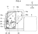
- Fig. 4 is a schematic side view showing a shifting state of the upper front window member section 18 of the cab 10 in the embodiment, and a position of a detector 50 to be described later.
- Fig. 4 excludes illustration of the getting-in-and-out section 17.
- the upper front window member section 18 is shiftable between a position (closing position) 18a to close the window opening section 13H ( Fig. 3 ) defined in the front wall 13 of the cab 10 and a position (opening position) 18b where the upper front window member section is accommodated below the top wall 11 of the cab 10 to open the window opening section 13H in the cab 10, as denoted by a long dashed and double-short dashed line in Fig. 4 .
- the upper front window member section 18 has an inner end X (on an inner plane) forming a shift locus in an arc shape in a front upper area of the cab 10 as denoted by a dashed line in Fig. 4 in a side view.
- the shift locus of the upper front window member section 18 falls within a range enclosed by: the inner end X having the arc shape to connect a lower portion of the front wall 13 than a center thereof in the up-down direction to a rear portion of the top wall 11 from the center thereof in the front-rear direction; the upper front window member section 18 at the closing position 18a; and the upper front window member section 18 at the opening position 18b.
- Each of the left and right front pillars 13a has an unillustrated rail for allowing the upper front window member section 18 to slide therein.
- each of the left and right top frame members 11a has an unillustrated rail for allowing the upper front window member 18 to slide therein in the front-rear direction.
- the cab 10 includes, in the inside, an operator seat 20 disposed on the bottom wall 12 for allowing the operator to sit thereon.
- the operator seat 20 has an upper portion provided with a headrest 20a.
- a console box 22 including a manipulation lever 21 for manipulating the attachment 4 is provided on each of left and right sides of the operator seat 20.
- a traveling pedal 23 and a traveling lever 24 are provided in front of and below the operator seat 20.
- the side wall 16 of the cab 10 facing the getting-in-and-out section 17 in the left-right direction is provided with a panel 30.
- the panel 30 protrudes upward from a front and lower portion of the side wall 16.
- the right side wall 16 of the cab 10 adjacent to the attachment 4 has the lower portion provided with an air conditioning unit, a ventilation duct, and various wires (not shown).
- the panel 30 extends upward from the bottom wall 12 to cover the air conditioning unit and other elements, and forms an inner surface of the side wall 16.
- the panel 30 obliquely extends upward from a vicinity of the operator seat 20 to the front pillar 13a to be gradually higher as advancing from the rear to the front.
- Fig. 5 is a perspective view of the main portion of the cab 10 in the embodiment.
- Fig. 5 excludes illustration of the front window 13W ( Fig. 3 ).
- the panel 30 has a plurality of outlet holes 30a for an air conditioner.
- the side wall 16 has a right window 16a (side window) located above the panel 30.
- the hydraulic excavator 1 further includes a display device 40 fixedly attached to an upper portion (top) of the panel 30. Specifically, as shown in Fig. 4 , the upper portion of the panel 30 to which the display device 40 is fixedly attached is at a position higher than a seat base of the operator seat 20 and lower than the headrest 20a.
- the display device 40 includes a display part 41 and a display part support member 42 (display screen attaching bracket) for supporting the display part 41.
- the display device 40 is fixedly attached to the panel 30 at the display part support member 42.
- the display part 41 includes a display part main body 41a ( Fig. 6 ) having a display screen, such as a touch screen, and an outer frame surrounding the display screen.
- the outer frame of the display part 41 is made of, for example, resin material.
- the display part main body 41a of the display part 41 has a back surface on which a box-shaped container 41b for accommodating electrical components is disposed.
- the box-shaped container 41b is located in a substantially right-half region of the display part main body 41a.
- the display part 41 can display various kinds of information representing a state of the hydraulic excavator 1, e.g., as indicated by a cluster gauge, and the operator can manipulate the display part 41.
- the display part 41 is attached to the display part support member 42 in a posture of facing the headrest 20a at a position obliquely downward from a sightline of the operator so as to be visible and operable by the operator sitting on the operator seat 20.
- the display part support member 42 is made of, for example, metal material.
- the display part support member 42 has a display part support plate 42a, a fixing section 42b, and a fixed section 42c.
- the display part support plate 42a is a rectangular flat member extending along a back surface (surface located at a front position in the front-rear direction) of the display part 41 as shown in Fig. 7 .
- the display part 41 is fastened to the display part support plate 42a with, for example, a bolt.
- the fixing section 42b is connected to the display part support plate 42a along a left edge thereof in such a manner as to extend rearward.
- the fixing section 42b agrees with a side surface of the box-shaped container 41b of the display part 41.
- the fixed section 42c is connected to a right end of the display part support plate 42a in such a manner as to extend frontward.
- the fixed section 42c has a front end extending downward farther than the display part support plate 42a and formed with three screw holes at intervals in the up-down direction. Each of the screw holes receives a screw 42d inserted therethrough so that the fixed section 42c is fixedly attached to the upper portion of the panel 30.
- the panel 30 has an exterior made of resin except a specific portion where the fixed section 42c made of metal is fixed and exposed.
- the display part support plate 42a and the fixed section 42c form a predetermined angle therebetween in a plan view. With this configuration, the display part 41 fixedly attached to the display part support plate 42a is arranged to face the headrest 20a at the position obliquely downward from the sightline of the operator so as to be visible and operative by the operator sitting on the operator seat 20.
- the hydraulic excavator 1 further includes the detector 50.
- the detector 50 is fixedly connected to the display device 40 so as to be located at a position closer to the center of the cab 10 in the left-right direction thereof than an inner (left) surface of the display device 40 in the left-right direction thereof.
- the hydraulic excavator 1 further includes a detector retainer 43 (retainer) ( Fig. 6 , Fig. 7 ).
- the detector retainer 43 extends from the fixing section 42b at a left edge portion of the display part support member 42 toward the center of the cab 10 in the left-right direction thereof, and the detector retainer 43 further has a distal end to which the detector 50 is fixedly attached. As also shown in Fig.
- the distal end of the detector retainer 43 bends frontward to form a detector attachment section 43a.
- the detector attachment section 43 retains (fixedly holds) the detector 50.
- the detector retainer 43 causes the detector 50 to be spaced leftward from the display part 41.
- the detector 50 is firmly connected to the panel 30 via the display part support member 42 and the detector retainer 43 each made of metal.
- the detector retainer 43 has a proximal end 43b which may be connected (fixedly attached) to the fixing section 42b of the display part support member 42 by way of welding, a bolt, adhesion, or other way. In this manner, the detector 50 is retrofittable to a display device 40 preliminarily fixedly attached to the panel 30 in the hydraulic excavator 1.
- the detector 50 is arranged (fixed) at an inner position than the shift locus of the upper front window member section 18 (transparent member) in the cab 10, i.e., at a rear position therein.
- This configuration can ensure the detection accuracy of the detector 50 without contact between the detector 50 and the upper front window member section 18 even in opening and closing of the upper front window member section 18.
- the upper front window member section 18 is smoothly openable and closable.
- the detector 50 faces frontward to detect information in front of the upper slewing body 3.
- the detector 50 includes, for example, an image-capturing device like a camera, or a sensor like a RIDAR and a millimeter-wave radar.
- the detector 50 is a camera which can capture an image in front of the upper slewing body 3.
- the display part support member 42 supporting the display device 40 is made of material having high attachment strength, such as metal.
- the attachment strength of the detector 50 is easily ensured owing to the connection of the detector retainer 43 to the display part support member 42 and the fixed attachment of the detector 50 to the end of the detector retainer 43.
- This configuration eliminates the need of changing each frame member (e.g., pillar) of the cab 10, and thus achieves facilitated attachment of the detector 50.
- the detector 50 is easily retrofittable to an already provided display device 40.
- the display device 40 is disposed in the corner defined between the right side wall 16 and the front wall 13 in the cab 10 while being fixedly attached to the right side wall 16.
- the detector 50 is fixedly connected to the display device 40. This arrangement allows the detector 50 to be spaced apart from the right front pillar 13a, and thus can keep the front pillar 13a and other frame members from entering the detection range of the detector 50 and ensure the detection accuracy.
- the detector 50 can detect a range approximating to a vision field of the operator on the operator seat 20.
- the display device 40 is at an inner position than the left and right front pillars 13a in the left-right direction and faces the front window 13W in the front-rear direction.
- This arrangement allows the detector 50 to be further spaced apart from each front pillar 13a, and accordingly, the detector 50 can detect a range further approximating to the vision field of the operator.
- the detector 50 is fixedly connected to the display device 40. Accordingly, when the display device 40 displays an image captured by the detector 50, the operator can easily grasp an orientation and a position of the captured image. In other words, it takes a long time to intuitively grasp an orientation of a captured image displayed on the display device 40 in a configuration where the detector 50 and the display device 40 are at different positions from each other. In the configuration where the detector 50 is fixedly connected to the display device 40, the operator has many occasions to look around the display device 40, for example, when getting in the cab. Accordingly, the operator can easily find a physical malfunction of the detector 50.
- the right side wall 16 has the right window 16a and the panel 30 located below the right window 16a and in the cab 10, and the display device 40 is fixedly attached to the upper portion of the panel 30.
- the display device 40 is easily and stably fixed in the corner.
- the position of the detector 50 is stably kept.
- the display device 40 is fixedly attached to the upper portion of the panel 30, and therefore, the display device 40 is easily arrangeable at a predetermined height from the bottom wall 12.
- the upper portion of the panel 30 obliquely extends upward as advancing to the front window 13W, and has the top to which the display device 40 is fixedly attached.
- the display device 40 is arrangeable at a relatively higher position to meet the sightline of the operator.
- the display device 40 may be fixedly attached to other portion of the panel 30.
- the panel 30 has the outlet hole 30a for blowing out air to at least a space between the front window 13W and the detector 50, as shown in Fig. 3 to Fig. 5 . Therefore, the air having blown out of the outlet hole 30a reaches the detector 50, resulting in preventing a large amount of dusts from being deposited and accumulating on the detector 50.
- a configuration where the detector 50 is in the form of a camera including lens suppresses a defect in a captured image attributed to dusts.
- warm air blowing out of the outlet hole 30a reduces fogging of a specific portion of the front window 13W located in front of the detector 50. Consequently, the detector 50 can accurately detect information in front.
- the working machine according to the present invention is not limited to the above-described embodiment, and covers various configurations.
- the detector 50 may be fixedly attached to the display device 40 to overlap the display device 40 (be hidden by the display device 40) within a dimension thereof from a view of the operator on the operator seat 20.
- the detector 50 may be arranged on the back surface (surface located at the front position in the front-rear direction) of the display part 41 to fall within the dimension of the display part 41, and fixedly attached thereto so as to be hidden by the display part 41 from the view of the operator on the operator seat 20.
- the detector 50 in this arrangement can avoid obstructing the vision field of the operator.
- the detector 50 having this configuration can detect a range approximating to the vision field of the operator in comparison with a detector 50 directly fixed to the front pillar 13a.
- the display device 40 may be provided to a front portion of the other (left) side wall 15 in the left-right direction. Specifically, the display device 40 may be disposed in another corner defined between the left side wall 15 and the front wall 13 in the cab 10 while being fixedly attached to the left side wall 15.
- the display device 40 may be attached to the front pillar 13a via, for example, a bracket (fixing member) without limitation to the upper portion of the panel 30.
- the display device 40 may be fixedly attached to the front wall 13 without limitation to the side walls 15, 16.
- the panel 30 may be arranged inside a portion of the front wall 13, corresponding to the lower front window member section 19 shown in Fig. 3 , which is not opened, and the display device 40 may be fixedly attached to the panel 30.
- the working machine according to the present invention may be another working machine without limitation to the hydraulic excavator.
Landscapes
- Engineering & Computer Science (AREA)
- Mining & Mineral Resources (AREA)
- Civil Engineering (AREA)
- General Engineering & Computer Science (AREA)
- Structural Engineering (AREA)
- Chemical & Material Sciences (AREA)
- Combustion & Propulsion (AREA)
- Transportation (AREA)
- Mechanical Engineering (AREA)
- Component Parts Of Construction Machinery (AREA)
Claims (7)
- Engin (1) de travaux, comprenant :un corps mobile inférieur (2) ;un corps pivotant supérieur (3) monté de façon pivotante sur le corps mobile inférieur (2) ;une cabine (10) montée sur le corps pivotant supérieur (3), la cabine (10) comprenant: une paroi avant (13) dotée d'une fenêtre avant (13W); une paire de montants avant gauche et droit (13a) s'étendant dans une direction haut-bas respectivement le long de côtés gauche et droit de la fenêtre avant (13W); et une paire de parois latérales gauche et droite (15, 16) s'étendant vers l'arrière respectivement à partir des montants avant gauche et droit (13a) ;un dispositif (40) d'affichage disposé dans un coin défini entre une des parois latérales gauche et droite (15, 16) et la paroi avant (13) dans la cabine (10) tout en étant en liaison complète avec la paroi latérale (16) considérée ou la paroi avant (13) pour afficher des informations prédéterminées ; etun détecteur (50) en liaison complète avec le dispositif (40) d'affichage pour détecter des informations en avant du corps pivotant supérieur (3),la paroi latérale (16) considérée étant dotée d'une fenêtre latérale (16a) et un panneau (30) situé au-dessous de la fenêtre latérale (16a) et dans la cabine (10), etle dispositif (40) d'affichage étant en liaison complète avec une partie supérieure du panneau (30),caractérisé en ce quele panneau (30) est doté d'un trou (30a) de sortie servant à souffler de l'air vers au moins un espace entre la fenêtre avant (13W) et le détecteur (50).
- Engin (1) de travaux selon la revendication 1,
le dispositif (40) d'affichage se trouvant dans une position intérieure par rapport aux montants avant gauche et droit (13a) dans une direction gauche-droite et faisant face à la fenêtre avant (13W) dans une direction avant-arrière. - Engin (1) de travaux selon la revendication 1 ou 2,la partie supérieure du panneau (30) s'étendant obliquement vers le haut en s'avançant vers la fenêtre avant (13W), etle dispositif (40) d'affichage étant en liaison complète avec un dessus de la partie supérieure du panneau (30).
- Engin (1) de travaux selon l'une quelconque des revendications 1 à 3,
le détecteur (50) étant en liaison complète avec le dispositif (40) d'affichage de façon à être situé dans une position plus proche d'un centre de la cabine (10) dans la direction gauche-droite de celle-ci qu'une surface intérieure du dispositif (40) d'affichage dans la direction gauche-droite de celui-ci. - Engin (1) de travaux selon l'une quelconque des revendications 1 à 4,
le dispositif (40) d'affichage comprenant :une partie (41) d'affichage ; etun élément (42) de support de partie d'affichage en liaison complète avec la paroi latérale (15, 16) considérée ou la paroi avant (13) pour supporter la partie (41) d'affichage, l'engin (1) de travaux comportant en outre un élément (43) de retenue lié à l'élément (42) de support de partie d'affichage pour retenir le détecteur (50). - Engin (1) de travaux selon l'une quelconque des revendications 1 à 5,la cabine (10) comprenant un siège (20) d'opérateur configuré pour permettre à un opérateur de s'asseoir dessus, etle détecteur (50) étant en liaison complète avec le dispositif (40) d'affichage de façon à être caché par le dispositif (40) d'affichage à la vue de l'opérateur présent sur le siège (20) d'opérateur.
- Engin (1) de travaux selon l'une quelconque des revendications 1 à 6,la cabine (10) comprenant en outre une paroi supérieure (11),la fenêtre avant (13W) étant dotée d'une section (13H) d'ouverture de fenêtre définie dans la paroi avant (13) et étant munie d'un élément transparent (13P) pour la section (13H) d'ouverture de fenêtre,l'élément transparent (13P) étant situé au-dessous de la paroi supérieure (11) et configuré pour pouvoir être déplacé entre une position de fermeture et une position d'ouverture pour fermer la section (13H) d'ouverture de fenêtre dans la position de fermeture et ouvrir la section (13H) d'ouverture de fenêtre dans la position d'ouverture dans la cabine (10), etle détecteur (50) se trouvant en arrière d'un lieu de déplacement de l'élément transparent (13P) entre la position de fermeture et la position d'ouverture.
Applications Claiming Priority (1)
| Application Number | Priority Date | Filing Date | Title |
|---|---|---|---|
| JP2021161774A JP7661859B2 (ja) | 2021-09-30 | 2021-09-30 | 作業機械 |
Publications (2)
| Publication Number | Publication Date |
|---|---|
| EP4159934A1 EP4159934A1 (fr) | 2023-04-05 |
| EP4159934B1 true EP4159934B1 (fr) | 2024-02-21 |
Family
ID=83193444
Family Applications (1)
| Application Number | Title | Priority Date | Filing Date |
|---|---|---|---|
| EP22193839.2A Active EP4159934B1 (fr) | 2021-09-30 | 2022-09-05 | Machine de travail |
Country Status (4)
| Country | Link |
|---|---|
| US (1) | US12246780B2 (fr) |
| EP (1) | EP4159934B1 (fr) |
| JP (1) | JP7661859B2 (fr) |
| CN (1) | CN115897694A (fr) |
Families Citing this family (1)
| Publication number | Priority date | Publication date | Assignee | Title |
|---|---|---|---|---|
| JP2026053928A (ja) * | 2024-09-13 | 2026-03-26 | ヤンマーホールディングス株式会社 | 作業機械 |
Family Cites Families (19)
| Publication number | Priority date | Publication date | Assignee | Title |
|---|---|---|---|---|
| JPS61235104A (ja) | 1985-04-11 | 1986-10-20 | 平岡金属工業株式会社 | 遠心力利用製管機 |
| JP4569739B2 (ja) * | 2003-11-28 | 2010-10-27 | 日立建機株式会社 | 建設機械の表示装置 |
| EP1889007B1 (fr) | 2005-06-06 | 2009-08-26 | TomTom International B.V. | Dispositif de navigation utilisant une caméra |
| JP2007320547A (ja) * | 2006-06-01 | 2007-12-13 | Hiroko Sano | 自動車用前方視認装置 |
| JP6084613B2 (ja) * | 2012-07-19 | 2017-02-22 | 住友建機株式会社 | ショベル |
| DE112015006347T5 (de) | 2015-09-30 | 2017-12-07 | Komatsu Ltd. | Bildaufnahmevorrichtung |
| CN108432241B (zh) | 2015-12-28 | 2022-11-29 | 住友建机株式会社 | 挖土机 |
| WO2018012047A1 (fr) * | 2016-07-14 | 2018-01-18 | コベルコ建機株式会社 | Cabine pour engin de construction |
| DE112017000135T5 (de) * | 2017-03-31 | 2019-03-14 | Komatsu Ltd. | Arbeitsfahrzeug |
| CN110869566A (zh) | 2017-08-23 | 2020-03-06 | 住友建机株式会社 | 挖土机 |
| JP7155516B2 (ja) | 2017-12-20 | 2022-10-19 | コベルコ建機株式会社 | 建設機械 |
| JP6922730B2 (ja) * | 2017-12-27 | 2021-08-18 | コベルコ建機株式会社 | 建設機械の表示システム |
| JP6946172B2 (ja) * | 2017-12-27 | 2021-10-06 | 株式会社クボタ | 作業機 |
| JP6673391B2 (ja) * | 2018-03-29 | 2020-03-25 | コベルコ建機株式会社 | 作業機械 |
| JP7045926B2 (ja) | 2018-05-22 | 2022-04-01 | 株式会社小松製作所 | 油圧ショベル、およびシステム |
| JP7281794B2 (ja) * | 2018-12-25 | 2023-05-26 | 株式会社ユピテル | システム等 |
| WO2020196516A1 (fr) | 2019-03-26 | 2020-10-01 | 住友建機株式会社 | Pelle |
| CN114080481B (zh) * | 2019-07-17 | 2024-01-16 | 住友建机株式会社 | 施工机械及支援基于施工机械的作业的支援装置 |
| JP7518650B2 (ja) | 2020-03-31 | 2024-07-18 | 積水化学工業株式会社 | 排水システムおよび排水管の乾式埋め戻し施工工法 |
-
2021
- 2021-09-30 JP JP2021161774A patent/JP7661859B2/ja active Active
-
2022
- 2022-08-30 US US17/823,211 patent/US12246780B2/en active Active
- 2022-09-05 EP EP22193839.2A patent/EP4159934B1/fr active Active
- 2022-09-23 CN CN202211169355.4A patent/CN115897694A/zh active Pending
Also Published As
| Publication number | Publication date |
|---|---|
| CN115897694A (zh) | 2023-04-04 |
| US20230100150A1 (en) | 2023-03-30 |
| EP4159934A1 (fr) | 2023-04-05 |
| JP2023051224A (ja) | 2023-04-11 |
| US12246780B2 (en) | 2025-03-11 |
| JP7661859B2 (ja) | 2025-04-15 |
Similar Documents
| Publication | Publication Date | Title |
|---|---|---|
| JP5538575B1 (ja) | コントローラ組立体、作業機械のキャブおよび作業機械 | |
| EP2107168B1 (fr) | Structure d'ensemble supérieur de machine de travail | |
| KR20010071427A (ko) | 건설기계용 캐브 | |
| EP3824142B1 (fr) | Position d'affichage pour cabine avec porte basculante | |
| EP4159934B1 (fr) | Machine de travail | |
| JP7592785B2 (ja) | キャブおよび作業車両 | |
| JP6875551B2 (ja) | 車両のモニタ配置構造 | |
| EP4306721A1 (fr) | Engin de chantier | |
| JP5536964B1 (ja) | 建設機械用キャブおよび建設機械 | |
| EP3842289B1 (fr) | Machine de travail comprenant une structure de rangement pour ranger une matière imprimée | |
| JP6003957B2 (ja) | 建設機械のインテリア配設構造 | |
| US9820393B2 (en) | Monitor and working vehicle provided with the monitor | |
| JP2021155957A (ja) | ショベル | |
| US20180051441A1 (en) | Cab and work vehicle | |
| JP2000170219A (ja) | 油圧ショベルのコントローラ配置構造 | |
| JP7567623B2 (ja) | 作業機械のキャブ | |
| JP7534933B2 (ja) | 建設機械 | |
| JP2002173956A (ja) | 油圧ショベルのモニタ装置 | |
| WO2025187321A1 (fr) | Appareil de prise de vues, structure de fixation d'appareil de prise de vues et machine de travail | |
| JP2005112049A (ja) | エンジンルームのカバー装置 | |
| JP2019173506A (ja) | 作業機械 | |
| JP2025136588A (ja) | 作業機 | |
| JP2001213198A (ja) | 建設機械の表示装置 | |
| KR20260046002A (ko) | 작업 기계 제어 방법, 작업 기계 제어 프로그램, 작업 기계 디스플레이 시스템 및 작업 기계 | |
| JP2000257117A (ja) | 運転室付き建設機械 |
Legal Events
| Date | Code | Title | Description |
|---|---|---|---|
| PUAI | Public reference made under article 153(3) epc to a published international application that has entered the european phase |
Free format text: ORIGINAL CODE: 0009012 |
|
| STAA | Information on the status of an ep patent application or granted ep patent |
Free format text: STATUS: THE APPLICATION HAS BEEN PUBLISHED |
|
| AK | Designated contracting states |
Kind code of ref document: A1 Designated state(s): AL AT BE BG CH CY CZ DE DK EE ES FI FR GB GR HR HU IE IS IT LI LT LU LV MC MK MT NL NO PL PT RO RS SE SI SK SM TR |
|
| STAA | Information on the status of an ep patent application or granted ep patent |
Free format text: STATUS: REQUEST FOR EXAMINATION WAS MADE |
|
| 17P | Request for examination filed |
Effective date: 20230801 |
|
| GRAP | Despatch of communication of intention to grant a patent |
Free format text: ORIGINAL CODE: EPIDOSNIGR1 |
|
| STAA | Information on the status of an ep patent application or granted ep patent |
Free format text: STATUS: GRANT OF PATENT IS INTENDED |
|
| INTG | Intention to grant announced |
Effective date: 20231006 |
|
| GRAS | Grant fee paid |
Free format text: ORIGINAL CODE: EPIDOSNIGR3 |
|
| GRAA | (expected) grant |
Free format text: ORIGINAL CODE: 0009210 |
|
| STAA | Information on the status of an ep patent application or granted ep patent |
Free format text: STATUS: THE PATENT HAS BEEN GRANTED |
|
| AK | Designated contracting states |
Kind code of ref document: B1 Designated state(s): AL AT BE BG CH CY CZ DE DK EE ES FI FR GB GR HR HU IE IS IT LI LT LU LV MC MK MT NL NO PL PT RO RS SE SI SK SM TR |
|
| REG | Reference to a national code |
Ref country code: GB Ref legal event code: FG4D |
|
| REG | Reference to a national code |
Ref country code: CH Ref legal event code: EP |
|
| REG | Reference to a national code |
Ref country code: DE Ref legal event code: R096 Ref document number: 602022002049 Country of ref document: DE |
|
| REG | Reference to a national code |
Ref country code: IE Ref legal event code: FG4D |
|
| REG | Reference to a national code |
Ref country code: LT Ref legal event code: MG9D |
|
| REG | Reference to a national code |
Ref country code: NL Ref legal event code: MP Effective date: 20240221 |
|
| PG25 | Lapsed in a contracting state [announced via postgrant information from national office to epo] |
Ref country code: IS Free format text: LAPSE BECAUSE OF FAILURE TO SUBMIT A TRANSLATION OF THE DESCRIPTION OR TO PAY THE FEE WITHIN THE PRESCRIBED TIME-LIMIT Effective date: 20240621 |
|
| PG25 | Lapsed in a contracting state [announced via postgrant information from national office to epo] |
Ref country code: LT Free format text: LAPSE BECAUSE OF FAILURE TO SUBMIT A TRANSLATION OF THE DESCRIPTION OR TO PAY THE FEE WITHIN THE PRESCRIBED TIME-LIMIT Effective date: 20240221 |
|
| PG25 | Lapsed in a contracting state [announced via postgrant information from national office to epo] |
Ref country code: GR Free format text: LAPSE BECAUSE OF FAILURE TO SUBMIT A TRANSLATION OF THE DESCRIPTION OR TO PAY THE FEE WITHIN THE PRESCRIBED TIME-LIMIT Effective date: 20240522 |
|
| REG | Reference to a national code |
Ref country code: AT Ref legal event code: MK05 Ref document number: 1659236 Country of ref document: AT Kind code of ref document: T Effective date: 20240221 |
|
| PG25 | Lapsed in a contracting state [announced via postgrant information from national office to epo] |
Ref country code: NL Free format text: LAPSE BECAUSE OF FAILURE TO SUBMIT A TRANSLATION OF THE DESCRIPTION OR TO PAY THE FEE WITHIN THE PRESCRIBED TIME-LIMIT Effective date: 20240221 Ref country code: HR Free format text: LAPSE BECAUSE OF FAILURE TO SUBMIT A TRANSLATION OF THE DESCRIPTION OR TO PAY THE FEE WITHIN THE PRESCRIBED TIME-LIMIT Effective date: 20240221 Ref country code: RS Free format text: LAPSE BECAUSE OF FAILURE TO SUBMIT A TRANSLATION OF THE DESCRIPTION OR TO PAY THE FEE WITHIN THE PRESCRIBED TIME-LIMIT Effective date: 20240521 |
|
| PG25 | Lapsed in a contracting state [announced via postgrant information from national office to epo] |
Ref country code: ES Free format text: LAPSE BECAUSE OF FAILURE TO SUBMIT A TRANSLATION OF THE DESCRIPTION OR TO PAY THE FEE WITHIN THE PRESCRIBED TIME-LIMIT Effective date: 20240221 |
|
| PG25 | Lapsed in a contracting state [announced via postgrant information from national office to epo] |
Ref country code: AT Free format text: LAPSE BECAUSE OF FAILURE TO SUBMIT A TRANSLATION OF THE DESCRIPTION OR TO PAY THE FEE WITHIN THE PRESCRIBED TIME-LIMIT Effective date: 20240221 |
|
| PG25 | Lapsed in a contracting state [announced via postgrant information from national office to epo] |
Ref country code: RS Free format text: LAPSE BECAUSE OF FAILURE TO SUBMIT A TRANSLATION OF THE DESCRIPTION OR TO PAY THE FEE WITHIN THE PRESCRIBED TIME-LIMIT Effective date: 20240521 Ref country code: NO Free format text: LAPSE BECAUSE OF FAILURE TO SUBMIT A TRANSLATION OF THE DESCRIPTION OR TO PAY THE FEE WITHIN THE PRESCRIBED TIME-LIMIT Effective date: 20240521 Ref country code: NL Free format text: LAPSE BECAUSE OF FAILURE TO SUBMIT A TRANSLATION OF THE DESCRIPTION OR TO PAY THE FEE WITHIN THE PRESCRIBED TIME-LIMIT Effective date: 20240221 Ref country code: LT Free format text: LAPSE BECAUSE OF FAILURE TO SUBMIT A TRANSLATION OF THE DESCRIPTION OR TO PAY THE FEE WITHIN THE PRESCRIBED TIME-LIMIT Effective date: 20240221 Ref country code: IS Free format text: LAPSE BECAUSE OF FAILURE TO SUBMIT A TRANSLATION OF THE DESCRIPTION OR TO PAY THE FEE WITHIN THE PRESCRIBED TIME-LIMIT Effective date: 20240621 Ref country code: HR Free format text: LAPSE BECAUSE OF FAILURE TO SUBMIT A TRANSLATION OF THE DESCRIPTION OR TO PAY THE FEE WITHIN THE PRESCRIBED TIME-LIMIT Effective date: 20240221 Ref country code: GR Free format text: LAPSE BECAUSE OF FAILURE TO SUBMIT A TRANSLATION OF THE DESCRIPTION OR TO PAY THE FEE WITHIN THE PRESCRIBED TIME-LIMIT Effective date: 20240522 Ref country code: FI Free format text: LAPSE BECAUSE OF FAILURE TO SUBMIT A TRANSLATION OF THE DESCRIPTION OR TO PAY THE FEE WITHIN THE PRESCRIBED TIME-LIMIT Effective date: 20240221 Ref country code: ES Free format text: LAPSE BECAUSE OF FAILURE TO SUBMIT A TRANSLATION OF THE DESCRIPTION OR TO PAY THE FEE WITHIN THE PRESCRIBED TIME-LIMIT Effective date: 20240221 Ref country code: BG Free format text: LAPSE BECAUSE OF FAILURE TO SUBMIT A TRANSLATION OF THE DESCRIPTION OR TO PAY THE FEE WITHIN THE PRESCRIBED TIME-LIMIT Effective date: 20240221 Ref country code: AT Free format text: LAPSE BECAUSE OF FAILURE TO SUBMIT A TRANSLATION OF THE DESCRIPTION OR TO PAY THE FEE WITHIN THE PRESCRIBED TIME-LIMIT Effective date: 20240221 |
|
| PG25 | Lapsed in a contracting state [announced via postgrant information from national office to epo] |
Ref country code: PT Free format text: LAPSE BECAUSE OF FAILURE TO SUBMIT A TRANSLATION OF THE DESCRIPTION OR TO PAY THE FEE WITHIN THE PRESCRIBED TIME-LIMIT Effective date: 20240621 Ref country code: PL Free format text: LAPSE BECAUSE OF FAILURE TO SUBMIT A TRANSLATION OF THE DESCRIPTION OR TO PAY THE FEE WITHIN THE PRESCRIBED TIME-LIMIT Effective date: 20240221 |
|
| PG25 | Lapsed in a contracting state [announced via postgrant information from national office to epo] |
Ref country code: SE Free format text: LAPSE BECAUSE OF FAILURE TO SUBMIT A TRANSLATION OF THE DESCRIPTION OR TO PAY THE FEE WITHIN THE PRESCRIBED TIME-LIMIT Effective date: 20240221 Ref country code: PT Free format text: LAPSE BECAUSE OF FAILURE TO SUBMIT A TRANSLATION OF THE DESCRIPTION OR TO PAY THE FEE WITHIN THE PRESCRIBED TIME-LIMIT Effective date: 20240621 Ref country code: PL Free format text: LAPSE BECAUSE OF FAILURE TO SUBMIT A TRANSLATION OF THE DESCRIPTION OR TO PAY THE FEE WITHIN THE PRESCRIBED TIME-LIMIT Effective date: 20240221 Ref country code: LV Free format text: LAPSE BECAUSE OF FAILURE TO SUBMIT A TRANSLATION OF THE DESCRIPTION OR TO PAY THE FEE WITHIN THE PRESCRIBED TIME-LIMIT Effective date: 20240221 |
|
| PG25 | Lapsed in a contracting state [announced via postgrant information from national office to epo] |
Ref country code: DK Free format text: LAPSE BECAUSE OF FAILURE TO SUBMIT A TRANSLATION OF THE DESCRIPTION OR TO PAY THE FEE WITHIN THE PRESCRIBED TIME-LIMIT Effective date: 20240221 |
|
| PG25 | Lapsed in a contracting state [announced via postgrant information from national office to epo] |
Ref country code: SM Free format text: LAPSE BECAUSE OF FAILURE TO SUBMIT A TRANSLATION OF THE DESCRIPTION OR TO PAY THE FEE WITHIN THE PRESCRIBED TIME-LIMIT Effective date: 20240221 |
|
| PG25 | Lapsed in a contracting state [announced via postgrant information from national office to epo] |
Ref country code: EE Free format text: LAPSE BECAUSE OF FAILURE TO SUBMIT A TRANSLATION OF THE DESCRIPTION OR TO PAY THE FEE WITHIN THE PRESCRIBED TIME-LIMIT Effective date: 20240221 Ref country code: CZ Free format text: LAPSE BECAUSE OF FAILURE TO SUBMIT A TRANSLATION OF THE DESCRIPTION OR TO PAY THE FEE WITHIN THE PRESCRIBED TIME-LIMIT Effective date: 20240221 |
|
| PG25 | Lapsed in a contracting state [announced via postgrant information from national office to epo] |
Ref country code: SK Free format text: LAPSE BECAUSE OF FAILURE TO SUBMIT A TRANSLATION OF THE DESCRIPTION OR TO PAY THE FEE WITHIN THE PRESCRIBED TIME-LIMIT Effective date: 20240221 |
|
| PG25 | Lapsed in a contracting state [announced via postgrant information from national office to epo] |
Ref country code: SM Free format text: LAPSE BECAUSE OF FAILURE TO SUBMIT A TRANSLATION OF THE DESCRIPTION OR TO PAY THE FEE WITHIN THE PRESCRIBED TIME-LIMIT Effective date: 20240221 Ref country code: SK Free format text: LAPSE BECAUSE OF FAILURE TO SUBMIT A TRANSLATION OF THE DESCRIPTION OR TO PAY THE FEE WITHIN THE PRESCRIBED TIME-LIMIT Effective date: 20240221 Ref country code: RO Free format text: LAPSE BECAUSE OF FAILURE TO SUBMIT A TRANSLATION OF THE DESCRIPTION OR TO PAY THE FEE WITHIN THE PRESCRIBED TIME-LIMIT Effective date: 20240221 Ref country code: EE Free format text: LAPSE BECAUSE OF FAILURE TO SUBMIT A TRANSLATION OF THE DESCRIPTION OR TO PAY THE FEE WITHIN THE PRESCRIBED TIME-LIMIT Effective date: 20240221 Ref country code: DK Free format text: LAPSE BECAUSE OF FAILURE TO SUBMIT A TRANSLATION OF THE DESCRIPTION OR TO PAY THE FEE WITHIN THE PRESCRIBED TIME-LIMIT Effective date: 20240221 Ref country code: CZ Free format text: LAPSE BECAUSE OF FAILURE TO SUBMIT A TRANSLATION OF THE DESCRIPTION OR TO PAY THE FEE WITHIN THE PRESCRIBED TIME-LIMIT Effective date: 20240221 |
|
| REG | Reference to a national code |
Ref country code: DE Ref legal event code: R097 Ref document number: 602022002049 Country of ref document: DE |
|
| PG25 | Lapsed in a contracting state [announced via postgrant information from national office to epo] |
Ref country code: IT Free format text: LAPSE BECAUSE OF FAILURE TO SUBMIT A TRANSLATION OF THE DESCRIPTION OR TO PAY THE FEE WITHIN THE PRESCRIBED TIME-LIMIT Effective date: 20240221 |
|
| PLBE | No opposition filed within time limit |
Free format text: ORIGINAL CODE: 0009261 |
|
| STAA | Information on the status of an ep patent application or granted ep patent |
Free format text: STATUS: NO OPPOSITION FILED WITHIN TIME LIMIT |
|
| PG25 | Lapsed in a contracting state [announced via postgrant information from national office to epo] |
Ref country code: IT Free format text: LAPSE BECAUSE OF FAILURE TO SUBMIT A TRANSLATION OF THE DESCRIPTION OR TO PAY THE FEE WITHIN THE PRESCRIBED TIME-LIMIT Effective date: 20240221 |
|
| 26N | No opposition filed |
Effective date: 20241122 |
|
| PG25 | Lapsed in a contracting state [announced via postgrant information from national office to epo] |
Ref country code: SI Free format text: LAPSE BECAUSE OF FAILURE TO SUBMIT A TRANSLATION OF THE DESCRIPTION OR TO PAY THE FEE WITHIN THE PRESCRIBED TIME-LIMIT Effective date: 20240221 Ref country code: MC Free format text: LAPSE BECAUSE OF FAILURE TO SUBMIT A TRANSLATION OF THE DESCRIPTION OR TO PAY THE FEE WITHIN THE PRESCRIBED TIME-LIMIT Effective date: 20240221 |
|
| PG25 | Lapsed in a contracting state [announced via postgrant information from national office to epo] |
Ref country code: LU Free format text: LAPSE BECAUSE OF NON-PAYMENT OF DUE FEES Effective date: 20240905 |
|
| REG | Reference to a national code |
Ref country code: BE Ref legal event code: MM Effective date: 20240930 |
|
| PG25 | Lapsed in a contracting state [announced via postgrant information from national office to epo] |
Ref country code: BE Free format text: LAPSE BECAUSE OF NON-PAYMENT OF DUE FEES Effective date: 20240930 |
|
| PG25 | Lapsed in a contracting state [announced via postgrant information from national office to epo] |
Ref country code: IE Free format text: LAPSE BECAUSE OF NON-PAYMENT OF DUE FEES Effective date: 20240905 |
|
| PGFP | Annual fee paid to national office [announced via postgrant information from national office to epo] |
Ref country code: DE Payment date: 20250730 Year of fee payment: 4 |
|
| PGFP | Annual fee paid to national office [announced via postgrant information from national office to epo] |
Ref country code: FR Payment date: 20250808 Year of fee payment: 4 |
|
| PG25 | Lapsed in a contracting state [announced via postgrant information from national office to epo] |
Ref country code: CY Free format text: LAPSE BECAUSE OF FAILURE TO SUBMIT A TRANSLATION OF THE DESCRIPTION OR TO PAY THE FEE WITHIN THE PRESCRIBED TIME-LIMIT; INVALID AB INITIO Effective date: 20220905 |
|
| PG25 | Lapsed in a contracting state [announced via postgrant information from national office to epo] |
Ref country code: HU Free format text: LAPSE BECAUSE OF FAILURE TO SUBMIT A TRANSLATION OF THE DESCRIPTION OR TO PAY THE FEE WITHIN THE PRESCRIBED TIME-LIMIT; INVALID AB INITIO Effective date: 20220905 |