EP4159939A1 - Véhicule ferroviaire avec dispositif de chasse d'eau - Google Patents
Véhicule ferroviaire avec dispositif de chasse d'eau Download PDFInfo
- Publication number
- EP4159939A1 EP4159939A1 EP22194019.0A EP22194019A EP4159939A1 EP 4159939 A1 EP4159939 A1 EP 4159939A1 EP 22194019 A EP22194019 A EP 22194019A EP 4159939 A1 EP4159939 A1 EP 4159939A1
- Authority
- EP
- European Patent Office
- Prior art keywords
- sensor
- toilet
- sensor signal
- triggering
- generates
- Prior art date
- Legal status (The legal status is an assumption and is not a legal conclusion. Google has not performed a legal analysis and makes no representation as to the accuracy of the status listed.)
- Withdrawn
Links
- 238000011010 flushing procedure Methods 0.000 title claims abstract description 63
- 238000000034 method Methods 0.000 claims abstract description 34
- XLYOFNOQVPJJNP-UHFFFAOYSA-N water Substances O XLYOFNOQVPJJNP-UHFFFAOYSA-N 0.000 claims description 29
- 230000001960 triggered effect Effects 0.000 claims description 11
- 238000013459 approach Methods 0.000 claims description 3
- 238000005192 partition Methods 0.000 description 6
- 241000894006 Bacteria Species 0.000 description 3
- 241000700605 Viruses Species 0.000 description 3
- 238000009434 installation Methods 0.000 description 2
- 230000005540 biological transmission Effects 0.000 description 1
- 230000001419 dependent effect Effects 0.000 description 1
- 230000004069 differentiation Effects 0.000 description 1
- 238000005457 optimization Methods 0.000 description 1
- 230000001681 protective effect Effects 0.000 description 1
Images




Classifications
-
- E—FIXED CONSTRUCTIONS
- E03—WATER SUPPLY; SEWERAGE
- E03D—WATER-CLOSETS OR URINALS WITH FLUSHING DEVICES; FLUSHING VALVES THEREFOR
- E03D5/00—Special constructions of flushing devices, e.g. closed flushing system
- E03D5/10—Special constructions of flushing devices, e.g. closed flushing system operated electrically, e.g. by a photo-cell; also combined with devices for opening or closing shutters in the bowl outlet and/or with devices for raising/or lowering seat and cover and/or for swiveling the bowl
- E03D5/105—Special constructions of flushing devices, e.g. closed flushing system operated electrically, e.g. by a photo-cell; also combined with devices for opening or closing shutters in the bowl outlet and/or with devices for raising/or lowering seat and cover and/or for swiveling the bowl touchless, e.g. using sensors
-
- E—FIXED CONSTRUCTIONS
- E03—WATER SUPPLY; SEWERAGE
- E03D—WATER-CLOSETS OR URINALS WITH FLUSHING DEVICES; FLUSHING VALVES THEREFOR
- E03D5/00—Special constructions of flushing devices, e.g. closed flushing system
- E03D5/02—Special constructions of flushing devices, e.g. closed flushing system operated mechanically or hydraulically (or pneumatically) also details such as push buttons, levers and pull-card therefor
- E03D5/06—Special constructions of flushing devices, e.g. closed flushing system operated mechanically or hydraulically (or pneumatically) also details such as push buttons, levers and pull-card therefor directly by the door
-
- E—FIXED CONSTRUCTIONS
- E03—WATER SUPPLY; SEWERAGE
- E03D—WATER-CLOSETS OR URINALS WITH FLUSHING DEVICES; FLUSHING VALVES THEREFOR
- E03D5/00—Special constructions of flushing devices, e.g. closed flushing system
- E03D5/02—Special constructions of flushing devices, e.g. closed flushing system operated mechanically or hydraulically (or pneumatically) also details such as push buttons, levers and pull-card therefor
- E03D5/08—Special constructions of flushing devices, e.g. closed flushing system operated mechanically or hydraulically (or pneumatically) also details such as push buttons, levers and pull-card therefor directly by the foot combined with devices for opening or closing shutters in the bowl outlet and/or with devices for raising or lowering seat and cover and/or for swiveling the bowl
-
- E—FIXED CONSTRUCTIONS
- E03—WATER SUPPLY; SEWERAGE
- E03D—WATER-CLOSETS OR URINALS WITH FLUSHING DEVICES; FLUSHING VALVES THEREFOR
- E03D5/00—Special constructions of flushing devices, e.g. closed flushing system
- E03D5/02—Special constructions of flushing devices, e.g. closed flushing system operated mechanically or hydraulically (or pneumatically) also details such as push buttons, levers and pull-card therefor
- E03D5/09—Special constructions of flushing devices, e.g. closed flushing system operated mechanically or hydraulically (or pneumatically) also details such as push buttons, levers and pull-card therefor directly by the hand
Definitions
- the invention relates to rail vehicles with toilets and toilet flushing devices and toilet flushing devices as such.
- Buttons for manual actuation are widely used in all areas (toilets, washrooms, etc.) of modern rail vehicles to control doors, flush toilets, garbage can flaps, hand dryers, etc. Their appearance is partly determined by European regulations such as the TSI PRM (tactile symbols, tactile triggering).
- Viruses and bacteria can spread from one user's hand to the next user's hand via the well-known buttons that are triggered by finger or palm pressure.
- the object of the invention is to optimize rail vehicles with regard to hygiene in view of the problems described above.
- the or at least one triggering device of the toilet flushing device can be actuated without contact.
- An essential advantage of the toilet flushing device according to the invention can be seen in the fact that it is not necessary to touch parts of the triggering device for the purpose of triggering a flushing process and transmission of bacteria or viruses can be avoided.
- the problem is solved in a simple and advantageous manner that passengers might find touching the toilet flush button unhygienic.
- the triggering device comprises a proximity sensor which reacts to approach and generates a sensor signal when approached, and the triggering device controls the triggering of the flushing process at least also as a function of the sensor signal.
- the triggering device enables gesture control by the user, with which the user can specify the amount of water for the next flushing process without contact.
- the triggering device comprises a first proximity sensor which reacts contact-free when approached and generates a first sensor signal when approached, and the triggering device comprises a second proximity sensor which reacts contact-free when approached and when approached generates a second sensor signal, and the triggering device has a control device which is connected to the first and second proximity sensors and triggers different flushing processes depending on the chronological order in which the first and second sensor signals occur.
- first and second are used here exclusively to distinguish between the proximity sensors and their sensor signals; they do not imply any priority or chronological order, which is why the “second” sensor signal can occur before or after the “first” sensor signal.
- first and second amounts of water, durations and time periods.
- the control device is preferably designed in such a way that it releases a first quantity of water for the flushing process when the first proximity sensor generates the first sensor signal and the second proximity sensor only generates the second sensor signal thereafter, preferably after the generation of the first sensor signal within a predetermined first period of time. and releases a second quantity of water for the flushing process if the second proximity sensor generates the second sensor signal and the first proximity sensor only generates the first sensor signal thereafter, preferably after the second sensor signal has been generated within a predetermined second period of time.
- the first amount of water is preferably greater than the second amount of water; In the last-mentioned configuration, the first amount of water can be referred to as a large amount of water and the second amount of water as a small amount of water.
- control device is designed in such a way that it enables the flushing process for a first period of time when the first proximity sensor generates the first sensor signal and the second proximity sensor only thereafter, preferably after the generation of the first sensor signal within a predetermined first period of time, generates the second sensor signal, and enables the rinsing process for a second period of time when the second proximity sensor generates the second sensor signal and the first proximity sensor only thereafter, preferably after the generation of the second sensor signal generates the first sensor signal within a predetermined second period of time.
- the first period of time is preferably longer than the second period of time; In the case of the latter embodiment, the first period of time can be referred to as a long period of time and the second period of time can be referred to as a short period of time.
- the first and second periods of time which should elapse at most between the sensor triggers in order to ensure the described differentiation between the different flushing processes, can be of the same length; alternatively, they may differ in length.
- the or at least one of the proximity sensors is preferably an infrared sensor. In a preferred embodiment, all of the proximity sensors are infrared sensors.
- the or at least one of the proximity sensors is structurally hidden and not visible.
- all proximity sensors are structurally hidden and not visible.
- the triggering device can be actuated both contactlessly and in a contact-controlled manner.
- the triggering device includes a foot switch that can be triggered by touch and enables the triggering device to be actuated by foot.
- the triggering device has a switch that indicates the locking status of a door assigned to the switch, and the triggering device triggers flushing when the switch Unlocking of the door, which is preferably the access door to the wet room equipped with the toilet, is signaled.
- the triggering device (or its control device) only triggers a flush if no flushing has been triggered since the door assigned to the switch was last locked, for example because a user of the toilet or the wet room has flushed had forgotten.
- a sensor that detects use of the toilet and generates a toilet use signal when use is detected.
- a toilet use signal is preferably generated when a person is sitting on the toilet or alternatively already when the toilet lid is in the open position.
- Such a sensor can also be referred to as a toilet use sensor.
- the triggering device only triggers a flush after unlocking the door if the toilet usage sensor has used the toilet since the door was last locked has signaled the toilet using the toilet use signal, but no flush has been triggered by the time the door is unlocked.
- the toilet flushing device is equipped with a pictogram that can be read tactilely is that explains or facilitates the operation of the toilet flushing device.
- the invention also relates to a wet cell. According to the invention it is provided that this is equipped with a toilet flushing device as described above.
- the invention also relates to a rail vehicle. According to the invention, it is provided that this is equipped with a toilet flushing device as described above or a wet cell as described above.
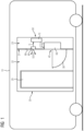
- the figure 1 shows a first exemplary embodiment of a rail vehicle 10 in a schematic cross-sectional representation, which is equipped with one or more sanitary units, of which FIG figure 1 one is shown by way of example and identified by the reference numeral 20.
- the wet room 20 is equipped with a toilet 30 attached to a partition wall 21 .
- the dividing wall 21 separates a section 22 of the wet room 20 that can be entered or used on the passing side from an installation section 23 of the wet room 20 that is covered by the dividing wall 21 .
- a toilet flushing device 40 is connected to the toilet 30 and is equipped with a triggering device 50 for triggering flushing processes.
- the triggering device 50 is connected to a water source 60, which is, for example, a water tank - as in the figure 1 shown - can act, which is equipped with an electrically or mechanically controllable valve.
- the controllable valve can be controlled by the triggering device by means of an electrical or mechanical triggering signal AS for the purpose of flushing the toilet 30 or for dispensing water.
- the water source 60 can also be a controllable shut-off valve alone, which is connected to a water line (not shown) of the rail vehicle 10 and can be opened by the triggering device 50 using the electrical or mechanical triggering signal AS to flush the toilet 30.
- the triggering device 50 includes a control device 70 which is connected to a proximity sensor 80 .
- the proximity sensor 80 is preferably an infrared sensor or a radar sensor that emits an infrared or radar signal SS and generates a sensor signal S when a body part approaches, for example, and transmits this to the triggering device.
- the proximity sensor 80 can be visible on the front - seen from the usable space section 22 - or hidden in the installation section 23.
- a visually and tactilely readable pictogram 90 is preferably arranged, which reveals the existence of the proximity sensor 80 and visualizes the possibility of actuation by approaching a finger, for example.
- the figure 2 shows the front of the partition wall 21 with the attached toilet 30 and the pictogram 90 in a plan view.
- the proximity sensor 80 covered by the partition wall 21 and the control device 70 covered by the partition wall 21 are shown with dashed lines.
- the figure 3 shows - in a plan view of the front of the partition 21 - a second exemplary embodiment of a wet cell 20 according to the invention of a rail vehicle 10.
- first proximity sensor 81 and a second proximity sensor 82 which are arranged next to one another and spaced apart from one another.
- the proximity sensors 81 and 82 can be arranged horizontally next to one another; alternatively, they can also be arranged vertically one above the other or completely differently.
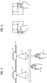
- the two proximity sensors 81 and 82 enable gesture control of the toilet flushing device 40 figure 4 recognize that a first sensor signal S1 can be generated contact-free by a hand movement in the direction of the first proximity sensor 81 and, subsequently, a second sensor signal S2 by pivoting the hand H in the direction of the second proximity sensor 82 and over it.
- the control device 70 will preferably trigger different flushing processes as a function of the chronological order in which the first and second sensor signals S1 and S2 occur.
- control device 70 can release a first, large amount of water for the flushing process if first proximity sensor 81 first generates the first sensor signal S1 and only then—within a predetermined maximum period of time—does second proximity sensor 82 generate the second sensor signal S2.
- a second amount of water which differs from the first amount of water and is, for example, smaller than the first and is therefore called small amount of water below, is released, for example, for the rinsing process if first the second proximity sensor 82 generates the second sensor signal S2 and only then--within the predetermined maximum period of time--does the first proximity sensor 81 generate the first sensor signal S1.
- the control device 70 can design the rinsing processes to have different lengths. For example, it can enable the rinsing process for a first, long period of time if the large amount of water is to be released, i.e. the first sensor signal S1 is generated before the second sensor signal S2, and the rinsing process for a second, short or shorter than the first period of time , release when the second sensor signal S2 is generated before the first sensor signal S1.
- the figure 5 shows the two proximity sensors 81 and 82 as part of a gesture control by a finger F, which is moved from left to right past the two proximity sensors 81 and 82 and thus triggers a flushing process with the large amount of water and the long period of time.
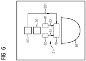
- the figure 6 shows - in a schematic plan view of the front of the partition 21 - a third exemplary embodiment of a wet cell 20 according to the invention of a rail vehicle 10.
- actuating device 100 which reacts to manual contact and is therefore touch-controlled.
- the actuating device 100 is connected to the control device 70 and this transmits an actuation signal BS1 when touched by the user and/or when the user exerts a contact pressure.
- the control device 70 If the actuation signal BS1 is present, then the control device 70 generates the trigger signal AS for triggering a flushing process.
- control device 70 triggers a rinsing process with the first large amount of water or the first, long rinsing duration when the actuation signal BS1 is present, i.e. the same rinsing process occurs as with a gesture control according to Figures 3 and 4 , so a triggering of the first proximity sensor 81 before the second proximity sensor 82, would have been the case.
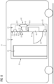
- the figure 7 shows the third embodiment in a schematic cross-sectional view.
- the figure 8 shows - in a schematic cross-sectional view - a fourth exemplary embodiment of a wet cell 20 according to the invention of a rail vehicle 10.
- the fourth exemplary embodiment there are two proximity sensors 81 and 82 which enable gesture control, as described above in connection with FIGS Figures 3 to 5 was explained.
- the components 81, 82 and 100 according to figure 8 can, for example, the components 81, 82 and 100 according to Figures 3 to 7 correspond, so that in this regard to the above explanations in connection with the Figures 3 to 7 be referred.
- a foot switch 110 is present in the fourth exemplary embodiment, which is arranged spatially below the toilet 30 and reacts to touch and enables actuation by foot.
- the foot switch 110 is connected to the control device 70 and transmits a foot switch-side actuation signal BS2 when touched and/or when the user exerts contact pressure.
- the control device 70 If the footswitch-side actuation signal BS2 of the footswitch 110 is present, the control device 70 generates the trigger signal AS for triggering a rinsing process.
- control device 70 triggers a rinsing process with the first large amount of water or the first long rinsing duration when the foot-switch-side actuation signal BS2 is present, i.e. the same rinsing process occurs as with a gesture control according to Figures 3 and 4 , so a triggering of the first proximity sensor 81 before the second proximity sensor 82, would have been the case.
- the figure 9 shows - in a schematic cross-sectional view - a fifth exemplary embodiment of a wet cell 20 according to the invention of a rail vehicle 10.
- the fifth embodiment there are two proximity sensors 81 and 82 that enable gesture control, as described above in connection with FIGS Figures 3 to 5 explained, an actuator 100, as above in connection with the figure 6 explained, and a footswitch 110, as related above with the figure 7 explained, available.
- the components 81, 82, 100 and 110 according to figure 8 can, for example, the components 81, 82 and 100 according to Figures 3 to 8 correspond, so that in this regard to the above explanations in connection with the Figures 3 to 8 be referred.
- a switch 120 is present in the fifth exemplary embodiment.
- the switch signals the respective locking state of a locking device 121 of an access door 25 of the wet room by means of a locking signal VS.
- the switch 120 is connected to the control device 70 and transmits the locking signal VS to it, so that the control device 70 knows the respective locking state of the access door 25 .
- the control device 70 triggers a flush by means of a trigger signal AS each time the switch 120 signals unlocking of the access door 25 .
- control device 70 triggers a flush only if no flush has been triggered since the access door 25 was last locked because none of the components 81, 82, 100 and 110 trigger a flush by transmitting suitable signals S1, S2, BS1 or BS2 initiated.
- the control device 70 preferably controls the flushing process in such a way that a flushing process with the first large amount of water or the first long flushing duration is triggered, i.e. the same flushing process occurs as with gesture control according to Figures 3 and 4 , so a triggering of the first proximity sensor 81 before the second proximity sensor 82, would have been the case.
- one of the two components 100 and 110 is omitted without replacement, ie either the actuating device 100 (first variant) or the foot switch 110 (second variant).
- both of the two components 100 and 110 are omitted without replacement, i.e. both the actuating device 100 and the foot switch 110.
- the figure 10 shows - in a schematic cross-sectional view - a sixth exemplary embodiment of a wet cell 20 according to the invention of a rail vehicle 10.
- a toilet use sensor 130 is additionally present, which detects use of the toilet 30 and generates a toilet use signal NS when use is detected.
- the toilet usage sensor 130 can be, for example, a proximity sensor, for example a radar or infrared sensor.
- the toilet use signal NS can be generated, for example, when a toilet lid is folded into the open position or only when a person is detected as sitting on the toilet.
- the control device 70 is designed in such a way that after the door contact switch 120 has detected the unlocking of the access door 25 by means of the locking signal VS, it only triggers a flush if the toilet use sensor 130 has been used since the last time the access door 25 was locked the toilet 30, but no flush had been triggered by the time it was unlocked.
- one of the two components 100 and 110 is omitted without replacement, ie either the actuating device 100 (first variant) or the foot switch 110 (second variant).
- both of the two components 100 and 110 are omitted without replacement, i.e. both the actuating device 100 and the foot switch 110.
- the actuator 100 as above in connection with the figure 6 explained, the foot switch 110, as above in connection with the figure 7 explained, the door contact switch 120, as above in connection with the figure 9 explained, and / or the toilet use sensor 130, as above in connection with figure 10 explained, also in the embodiment according to the figure 1 to be available.
- the proximity sensor 80 can itself also form the toilet use sensor 130 and thus replace it without replacement or also fulfill its function.
Landscapes
- Engineering & Computer Science (AREA)
- Aviation & Aerospace Engineering (AREA)
- Health & Medical Sciences (AREA)
- Life Sciences & Earth Sciences (AREA)
- Hydrology & Water Resources (AREA)
- Public Health (AREA)
- Water Supply & Treatment (AREA)
- Mechanical Engineering (AREA)
- Vehicle Waterproofing, Decoration, And Sanitation Devices (AREA)
Applications Claiming Priority (1)
| Application Number | Priority Date | Filing Date | Title |
|---|---|---|---|
| DE102021211001 | 2021-09-30 |
Publications (1)
| Publication Number | Publication Date |
|---|---|
| EP4159939A1 true EP4159939A1 (fr) | 2023-04-05 |
Family
ID=83228954
Family Applications (1)
| Application Number | Title | Priority Date | Filing Date |
|---|---|---|---|
| EP22194019.0A Withdrawn EP4159939A1 (fr) | 2021-09-30 | 2022-09-06 | Véhicule ferroviaire avec dispositif de chasse d'eau |
Country Status (1)
| Country | Link |
|---|---|
| EP (1) | EP4159939A1 (fr) |
Cited By (1)
| Publication number | Priority date | Publication date | Assignee | Title |
|---|---|---|---|---|
| DE102024113742A1 (de) * | 2024-05-16 | 2025-11-20 | Evac Gmbh | Betätigungsvorrichtung, System und Verfahren zum Steuern eines Wasserverbrauchs |
Citations (5)
| Publication number | Priority date | Publication date | Assignee | Title |
|---|---|---|---|---|
| EP1135559B1 (fr) * | 1999-10-06 | 2004-08-04 | Geberit Technik Ag | Dispositif d'actionnement de chasse d'eau sans contact pour des toilettes |
| US20170068228A1 (en) * | 2015-09-04 | 2017-03-09 | Grohe Ag | Method and assembly for operating a sanitary fixture |
| KR20210000298U (ko) * | 2019-07-29 | 2021-02-08 | 김흥준 | 양변기의 페달형 물내림 장치 |
| US20210222416A1 (en) * | 2020-01-16 | 2021-07-22 | Hydraze, Inc. | Programmable Toilet Flush Initiating, Monitoring and Management System and Method Thereof |
| CA3109019A1 (fr) * | 2020-03-25 | 2021-09-25 | Duravit Aktiengesellschaft | Installation sanitaire |
-
2022
- 2022-09-06 EP EP22194019.0A patent/EP4159939A1/fr not_active Withdrawn
Patent Citations (5)
| Publication number | Priority date | Publication date | Assignee | Title |
|---|---|---|---|---|
| EP1135559B1 (fr) * | 1999-10-06 | 2004-08-04 | Geberit Technik Ag | Dispositif d'actionnement de chasse d'eau sans contact pour des toilettes |
| US20170068228A1 (en) * | 2015-09-04 | 2017-03-09 | Grohe Ag | Method and assembly for operating a sanitary fixture |
| KR20210000298U (ko) * | 2019-07-29 | 2021-02-08 | 김흥준 | 양변기의 페달형 물내림 장치 |
| US20210222416A1 (en) * | 2020-01-16 | 2021-07-22 | Hydraze, Inc. | Programmable Toilet Flush Initiating, Monitoring and Management System and Method Thereof |
| CA3109019A1 (fr) * | 2020-03-25 | 2021-09-25 | Duravit Aktiengesellschaft | Installation sanitaire |
Cited By (2)
| Publication number | Priority date | Publication date | Assignee | Title |
|---|---|---|---|---|
| DE102024113742A1 (de) * | 2024-05-16 | 2025-11-20 | Evac Gmbh | Betätigungsvorrichtung, System und Verfahren zum Steuern eines Wasserverbrauchs |
| WO2025238031A1 (fr) * | 2024-05-16 | 2025-11-20 | Evac Gmbh | Dispositif d'actionnement, système et procédé de commande d'une consommation d'eau |
Similar Documents
| Publication | Publication Date | Title |
|---|---|---|
| DE102004019571B4 (de) | Vorrichtung zum Betätigen einer elektrischen oder mechanischen Schließeinrichtung an einer Tür und/oder einer Klappe eines Fahrzeugs | |
| EP1910631A1 (fr) | Dispositif de detecteur pour systeme de fermeture d'un vehicule automobile, et procede associe | |
| EP1774125A1 (fr) | Dispositif pour actionner un dispositif de fermeture electrique ou mecanique sur une portiere et/ou un volet d'un vehicule | |
| EP0825303A1 (fr) | Moyens de commande d'une vanne de décharge et/ou de chasse d'eau à dépression | |
| EP3519653A1 (fr) | Ensemble serrure de véhicule automobile | |
| EP3144436A1 (fr) | Procede et systeme de fonctionnement d'un dispositif sanitaire | |
| EP1964988B1 (fr) | Dispositif de chasse d'eau électromécanique | |
| EP4159939A1 (fr) | Véhicule ferroviaire avec dispositif de chasse d'eau | |
| DE10349926A1 (de) | Vorrichtung zum Verriegeln und zum Betätigen von Klappen, Türen od. dgl. | |
| EP3453803A1 (fr) | Dispositif d'actionnement permettant de faire fonctionner un dispositif de verrouillage destiné au verrouillage d'une ouverture d'écoulement | |
| EP3004717B1 (fr) | Porte d'ascenseur dotée d'un commutateur de contact de porte | |
| DE102011106786A1 (de) | Bedienelement, insbesondere für ein Automatikgetriebe eines Kraftfahrzeugs | |
| EP1135559B1 (fr) | Dispositif d'actionnement de chasse d'eau sans contact pour des toilettes | |
| EP3885501B1 (fr) | Dispositif sanitaire | |
| EP2388379A1 (fr) | Dispositif d'actionnement pour une chasse d'eau | |
| EP3763898B1 (fr) | Installation sanitaire et porte à battants en équerre | |
| DE102021123495A1 (de) | Flugzeug-Türschloss mit Antrieb | |
| DE102015003204B4 (de) | Bedienvorrichtung für ein Kraftfahrzeug, Kraftfahrzeug sowie Verfahren | |
| DE19945538C2 (de) | Verfahren zur Anzeige der Funktion eines Bedienelements sowie Vorrichtung zur Durchführung des Verfahrens | |
| DE102016123519A1 (de) | Verfahren zum Öffnen und/oder Schließen einer Tür oder Klappe eines Kraftfahrzeugs | |
| DE19932295C2 (de) | Vorrichtung zur Verstellung mindestens eines Fahrzeugsitzes | |
| EP1339923A1 (fr) | Dispositif de chasse sans contact pour w.-c., et procede d'actionnement sans contact d'une chasse de w.-c. | |
| DE10330334B4 (de) | Toilettensystem | |
| DE102004046903A1 (de) | Vorrichtung zur Auslösung eines Abfragesignals | |
| DE202013101922U1 (de) | Dampfbügelvorrichtung |
Legal Events
| Date | Code | Title | Description |
|---|---|---|---|
| PUAI | Public reference made under article 153(3) epc to a published international application that has entered the european phase |
Free format text: ORIGINAL CODE: 0009012 |
|
| STAA | Information on the status of an ep patent application or granted ep patent |
Free format text: STATUS: THE APPLICATION HAS BEEN PUBLISHED |
|
| AK | Designated contracting states |
Kind code of ref document: A1 Designated state(s): AL AT BE BG CH CY CZ DE DK EE ES FI FR GB GR HR HU IE IS IT LI LT LU LV MC MK MT NL NO PL PT RO RS SE SI SK SM TR |
|
| STAA | Information on the status of an ep patent application or granted ep patent |
Free format text: STATUS: THE APPLICATION IS DEEMED TO BE WITHDRAWN |
|
| 18D | Application deemed to be withdrawn |
Effective date: 20231006 |