EP4160026B1 - Stellglied mit doppelter elektrischer und pneumatischer steuerung - Google Patents
Stellglied mit doppelter elektrischer und pneumatischer steuerung Download PDFInfo
- Publication number
- EP4160026B1 EP4160026B1 EP22186757.5A EP22186757A EP4160026B1 EP 4160026 B1 EP4160026 B1 EP 4160026B1 EP 22186757 A EP22186757 A EP 22186757A EP 4160026 B1 EP4160026 B1 EP 4160026B1
- Authority
- EP
- European Patent Office
- Prior art keywords
- translation
- actuator
- electromagnet
- translation chamber
- chamber
- Prior art date
- Legal status (The legal status is an assumption and is not a legal conclusion. Google has not performed a legal analysis and makes no representation as to the accuracy of the status listed.)
- Active
Links
Images



Classifications
-
- F—MECHANICAL ENGINEERING; LIGHTING; HEATING; WEAPONS; BLASTING
- F15—FLUID-PRESSURE ACTUATORS; HYDRAULICS OR PNEUMATICS IN GENERAL
- F15B—SYSTEMS ACTING BY MEANS OF FLUIDS IN GENERAL; FLUID-PRESSURE ACTUATORS, e.g. SERVOMOTORS; DETAILS OF FLUID-PRESSURE SYSTEMS, NOT OTHERWISE PROVIDED FOR
- F15B15/00—Fluid-actuated devices for displacing a member from one position to another; Gearing associated therewith
- F15B15/08—Characterised by the construction of the motor unit
- F15B15/088—Characterised by the construction of the motor unit the motor using combined actuation, e.g. electric and fluid actuation
-
- E—FIXED CONSTRUCTIONS
- E05—LOCKS; KEYS; WINDOW OR DOOR FITTINGS; SAFES
- E05F—DEVICES FOR MOVING WINGS INTO OPEN OR CLOSED POSITION; CHECKS FOR WINGS; WING FITTINGS NOT OTHERWISE PROVIDED FOR, CONCERNED WITH THE FUNCTIONING OF THE WING
- E05F15/00—Power-operated mechanisms for wings
- E05F15/50—Power-operated mechanisms for wings using fluid-pressure actuators
-
- E—FIXED CONSTRUCTIONS
- E05—LOCKS; KEYS; WINDOW OR DOOR FITTINGS; SAFES
- E05F—DEVICES FOR MOVING WINGS INTO OPEN OR CLOSED POSITION; CHECKS FOR WINGS; WING FITTINGS NOT OTHERWISE PROVIDED FOR, CONCERNED WITH THE FUNCTIONING OF THE WING
- E05F15/00—Power-operated mechanisms for wings
- E05F15/60—Power-operated mechanisms for wings using electrical actuators
-
- E—FIXED CONSTRUCTIONS
- E05—LOCKS; KEYS; WINDOW OR DOOR FITTINGS; SAFES
- E05F—DEVICES FOR MOVING WINGS INTO OPEN OR CLOSED POSITION; CHECKS FOR WINGS; WING FITTINGS NOT OTHERWISE PROVIDED FOR, CONCERNED WITH THE FUNCTIONING OF THE WING
- E05F15/00—Power-operated mechanisms for wings
- E05F15/70—Power-operated mechanisms for wings with automatic actuation
- E05F15/72—Power-operated mechanisms for wings with automatic actuation responsive to emergency conditions, e.g. fire
-
- E—FIXED CONSTRUCTIONS
- E05—LOCKS; KEYS; WINDOW OR DOOR FITTINGS; SAFES
- E05Y—INDEXING SCHEME ASSOCIATED WITH SUBCLASSES E05D AND E05F, RELATING TO CONSTRUCTION ELEMENTS, ELECTRIC CONTROL, POWER SUPPLY, POWER SIGNAL OR TRANSMISSION, USER INTERFACES, MOUNTING OR COUPLING, DETAILS, ACCESSORIES, AUXILIARY OPERATIONS NOT OTHERWISE PROVIDED FOR, APPLICATION THEREOF
- E05Y2999/00—Subject-matter not otherwise provided for in this subclass
-
- F—MECHANICAL ENGINEERING; LIGHTING; HEATING; WEAPONS; BLASTING
- F15—FLUID-PRESSURE ACTUATORS; HYDRAULICS OR PNEUMATICS IN GENERAL
- F15B—SYSTEMS ACTING BY MEANS OF FLUIDS IN GENERAL; FLUID-PRESSURE ACTUATORS, e.g. SERVOMOTORS; DETAILS OF FLUID-PRESSURE SYSTEMS, NOT OTHERWISE PROVIDED FOR
- F15B15/00—Fluid-actuated devices for displacing a member from one position to another; Gearing associated therewith
- F15B15/08—Characterised by the construction of the motor unit
- F15B15/14—Characterised by the construction of the motor unit of the straight-cylinder type
- F15B15/1423—Component parts; Constructional details
- F15B15/1447—Pistons; Piston to piston rod assemblies
-
- F—MECHANICAL ENGINEERING; LIGHTING; HEATING; WEAPONS; BLASTING
- F15—FLUID-PRESSURE ACTUATORS; HYDRAULICS OR PNEUMATICS IN GENERAL
- F15B—SYSTEMS ACTING BY MEANS OF FLUIDS IN GENERAL; FLUID-PRESSURE ACTUATORS, e.g. SERVOMOTORS; DETAILS OF FLUID-PRESSURE SYSTEMS, NOT OTHERWISE PROVIDED FOR
- F15B15/00—Fluid-actuated devices for displacing a member from one position to another; Gearing associated therewith
- F15B15/20—Other details, e.g. assembly with regulating devices
- F15B15/26—Locking mechanisms
-
- F—MECHANICAL ENGINEERING; LIGHTING; HEATING; WEAPONS; BLASTING
- F15—FLUID-PRESSURE ACTUATORS; HYDRAULICS OR PNEUMATICS IN GENERAL
- F15B—SYSTEMS ACTING BY MEANS OF FLUIDS IN GENERAL; FLUID-PRESSURE ACTUATORS, e.g. SERVOMOTORS; DETAILS OF FLUID-PRESSURE SYSTEMS, NOT OTHERWISE PROVIDED FOR
- F15B15/00—Fluid-actuated devices for displacing a member from one position to another; Gearing associated therewith
- F15B15/20—Other details, e.g. assembly with regulating devices
- F15B2015/206—Combined actuation, e.g. electric and fluid actuated
-
- F—MECHANICAL ENGINEERING; LIGHTING; HEATING; WEAPONS; BLASTING
- F15—FLUID-PRESSURE ACTUATORS; HYDRAULICS OR PNEUMATICS IN GENERAL
- F15B—SYSTEMS ACTING BY MEANS OF FLUIDS IN GENERAL; FLUID-PRESSURE ACTUATORS, e.g. SERVOMOTORS; DETAILS OF FLUID-PRESSURE SYSTEMS, NOT OTHERWISE PROVIDED FOR
- F15B2211/00—Circuits for servomotor systems
- F15B2211/70—Output members, e.g. hydraulic motors or cylinders or control therefor
- F15B2211/705—Output members, e.g. hydraulic motors or cylinders or control therefor characterised by the type of output members or actuators
- F15B2211/7051—Linear output members
- F15B2211/7052—Single-acting output members
-
- F—MECHANICAL ENGINEERING; LIGHTING; HEATING; WEAPONS; BLASTING
- F15—FLUID-PRESSURE ACTUATORS; HYDRAULICS OR PNEUMATICS IN GENERAL
- F15B—SYSTEMS ACTING BY MEANS OF FLUIDS IN GENERAL; FLUID-PRESSURE ACTUATORS, e.g. SERVOMOTORS; DETAILS OF FLUID-PRESSURE SYSTEMS, NOT OTHERWISE PROVIDED FOR
- F15B2211/00—Circuits for servomotor systems
- F15B2211/80—Other types of control related to particular problems or conditions
- F15B2211/875—Control measures for coping with failures
- F15B2211/8752—Emergency operation mode, e.g. fail-safe operation mode
-
- F—MECHANICAL ENGINEERING; LIGHTING; HEATING; WEAPONS; BLASTING
- F15—FLUID-PRESSURE ACTUATORS; HYDRAULICS OR PNEUMATICS IN GENERAL
- F15B—SYSTEMS ACTING BY MEANS OF FLUIDS IN GENERAL; FLUID-PRESSURE ACTUATORS, e.g. SERVOMOTORS; DETAILS OF FLUID-PRESSURE SYSTEMS, NOT OTHERWISE PROVIDED FOR
- F15B2211/00—Circuits for servomotor systems
- F15B2211/80—Other types of control related to particular problems or conditions
- F15B2211/875—Control measures for coping with failures
- F15B2211/8757—Control measures for coping with failures using redundant components or assemblies
-
- F—MECHANICAL ENGINEERING; LIGHTING; HEATING; WEAPONS; BLASTING
- F15—FLUID-PRESSURE ACTUATORS; HYDRAULICS OR PNEUMATICS IN GENERAL
- F15B—SYSTEMS ACTING BY MEANS OF FLUIDS IN GENERAL; FLUID-PRESSURE ACTUATORS, e.g. SERVOMOTORS; DETAILS OF FLUID-PRESSURE SYSTEMS, NOT OTHERWISE PROVIDED FOR
- F15B2211/00—Circuits for servomotor systems
- F15B2211/80—Other types of control related to particular problems or conditions
- F15B2211/885—Control specific to the type of fluid, e.g. specific to magnetorheological fluid
- F15B2211/8855—Compressible fluids, e.g. specific to pneumatics
Definitions
- the present invention relates to the field of actuators, and relates more particularly to a pneumatically and electrically controlled actuator.
- actuators Electrically controlled actuators and pneumatically controlled actuators are known.
- Such actuators usually comprise a movable element received in a housing and movable under the effect of a piston between a retracted position and a position deployed outside the housing.
- Such actuators are commonly used in smoke extraction devices, the mobile element then being a push rod triggering the opening of a smoke extraction hatch, for example.
- the choice of the type of actuator to use depends on the installation.
- the actuator remains inoperative, which is particularly detrimental in the case of smoke extraction devices.
- the Applicant therefore proposes to meet these needs by using an actuator which integrates both pneumatic actuation means and electrical actuation means, which can be actuated both independently and simultaneously.
- Such an actuator has a compact configuration for dual operation. Also, such an actuator allows operation both independently and simultaneously in a pneumatic mode and in an electric mode. Such dual functionality allows, on the one hand, versatility and, on the other hand, allows use on different types of installations depending on the most appropriate actuation. The presence of actuation means of two different types allows also to benefit from the presence of secondary emergency actuation means in the event of failure of the actuation means previously defined as primary.
- the at least one projection may be, in the retracted position, completely in the translation chamber or partially project through the opening, the length of the projection outside the opening being greater in the trigger position for generate a force according to the direction of translation of the at least one projection on an element or object to be actuated located at a distance from the actuator less than the difference in projection length of the at least one projection between the trigger position and the retracted position.
- the elastic return element is a compression spring placed between the two elements, preferably surrounding the electromagnet.
- the elastic return element is a tension spring connected to the stop and disposed between the second element and the stop.
- the electromagnet is integral with the first element, the second element being made of a magnetic or magnetizable material.
- the electromagnet is integral with the second element, the first element being made of a magnetic or magnetizable material.
- the first element and the second element are made of a magnetic or magnetizable material.
- the actuator comprises means for locking in position of at least one of the two elements.
- the stop is constituted by the end of the translation chamber opposite the blind end.
- a slot is formed in the actuator in the part of the translation chamber upstream of the first element, to allow an electrical supply to the electromagnet, the slot allowing a stroke of the wires coming from the power supply electrical and powering the electromagnet.
- the first element and/or the second element allow sudden triggering of the stop so that it can, through the inertia generated, maneuver an element to be maneuvered.
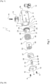
- an actuator 1 is represented. Such an actuator 1 is configured to actuate an element to be operated.
- the actuator 1 according to the present invention comprises a housing 2.
- the housing 2 shown on the Figures 1 to 4B is rectangular parallelepiped in shape.
- the housing 2 includes an internal hollow translation chamber 3.
- the translation chamber 3 defines a direction of translation between a first blind end 3b of the translation chamber 3 and an opposite end 5 in which an opening 4 is provided. This end 5 will subsequently be called front end 5. From before, means any side of the housing 2 intended in use to be placed opposite the element to be operated.
- the translation chamber 3 is of circular cylindrical shape and thus the opening 4 is of circular shape, the translation chamber 3 and the opening 4 being arranged centrally in the housing 2.
- the housing 2 comprises in in addition to an orifice 6 putting the translation chamber 3 in communication with the exterior of the housing 2.
- the orifice 6 is arranged on the housing 2 at the level of the blind end 3b, opposite the front end 5.
- the housing 2 is also equipped with a cover 7.
- the cover 7 has an orifice 8.
- the cover 7 is configured to partially obstruct the opening 4, the orifice 8 of the cover 7 then being brought opposite the opening 4 of the housing 2.
- the orifice 8 of the cover 7 is circular and of smaller diameter than that of the opening 4 of the housing 2.
- the cover 7 is fixed to the housing 2 by means of screws 9 passing through holes 10 made in the cover 7 and tapped holes 11 made in the front end 5 of the housing 2.
- screws 9 passing through holes 10 made in the cover 7 and tapped holes 11 made in the front end 5 of the housing 2.
- the cover 7 and the housing 2 can be made in one piece, the orifice then being directly formed in the front end of the housing.
- a slot 2f is formed on one side of the housing 2, extending from the front end 5 towards the rear of the housing 2, up to substantially before the position occupied by a seal 25 in the end position. race of one pneumatic piston 22 described below. The role of slot 2f will also be explained in more detail below.
- the actuator 1 comprises a pneumatic connection 12, which is connected to the housing 2 at the port 6.
- the pneumatic connection 12 is configured to connect the housing 2 to an external pneumatic circuit (shown in Figure 5 ), in particular, to circulate a fluid, such as air or a particular gas inside the translation chamber 3.
- the actuator 1 is also equipped with an electrical connector 13 connecting it to an external CE electrical circuit (represented in Figure 5 ).
- the electrical connector 13 is fixed to the housing 2 by means of a screw 14.
- those skilled in the art will be able to consider other means of securing the electrical connector 13 to the housing 2 without departing from the present invention .
- the actuator 1 comprises a trigger carrying a projection extending in the direction of translation and mounted movable in translation in the translation chamber 3 between a retracted position and an deployed trigger position.
- the actuator 1 thus comprises a push rod 15.
- the push rod 15 comprises a cylindrical axis 16, a first end 17 of which is provided with a head 18, optionally rounded as shown.
- the head 18 is configured to project through the orifice 8 out of the translation chamber 3 to come into contact with an element to be operated so that the push rod 15 pushes the element to be actuated.
- the second end 19 of the push rod 15 is provided with a nipple 20 whose role will be explained below.
- the push rod 15 is configured to be movable relative to the housing 2, between a retracted position and an deployed position, as can be seen more particularly on the Figures 2A , 3A And 4A .
- the push rod 15 passes through the orifice 8 of the cover 7, the orifice 8 of the cover 7 then having a diameter substantially greater than the diameter of the axis 16.
- Other geometries of the axis 16, of the push rod 15 and the orifice 8 of the cover 7 could be considered, provided that they are corresponding and allow the passage of the axis 16 through the orifice 8.
- the actuator 1 comprises pneumatic actuation means 21.
- the pneumatic actuation means 21 are configured to move the push rod 15 from the retracted position to the deployed position, as can be seen in the Figures 2A-2B And 3A-3B , respectively.
- the pneumatic actuation means 21 comprise a pneumatic piston 22.
- the pneumatic piston 22 is circular cylindrical, and more generally has an external geometry corresponding to the internal geometry of the translation chamber 3 of the housing 2, to allow translation of the pneumatic piston 22 in the translation chamber 3 of the housing 2.
- the pneumatic piston 22 is made of metallic material, in particular aluminum.
- the diameter of the cylindrical pneumatic piston 22 is substantially less than the diameter of the translation chamber 3 of the housing 2 so as to be received in a sealed manner inside the latter.
- the periphery 23 of the pneumatic piston 22, in contact with the internal surface of the translation chamber 3, is provided with a groove 24 in which a seal 25 is arranged.
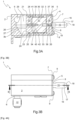
- the pneumatic piston 22 is configured to be movable inside the translation chamber 3 between a start of stroke position and an end of stroke position closer to the front end 5, the start of stroke position corresponding to the retracted position of the push rod 15 as shown on the Figure 2A , and the end position corresponding to the deployed position of the push rod 15 as shown in the Figure 3A .
- the pneumatic piston 22 has a front face 26 and an opposite rear face 27, the front face 26 being in use facing the internal face of the cover 7 of the housing 2.
- the pneumatic piston 22 has an orifice 28 whose role will be explained below.
- the pneumatic piston 22 is arranged on the blind end side 3b of the translation chamber 3 and defines on the rear face side 27 a sealed sub-chamber 29 within the translation chamber 3 and into which the orifice 6 opens.
- the volume of the sub-chamber 29 varies between a first volume defined when the pneumatic piston 22 is in the start position of the stroke, as shown on the Figure 2A , and a second volume, greater than the first volume, when the pneumatic piston 22 is in the end position, as shown in the Figure 3A .
- the sub-chamber 29 is filled with fluid coming from the pneumatic circuit and supplied via the orifice 6, the fluid being intended to exert a pneumatic action on the rear face 27 of the pneumatic piston 22, so as to move the pneumatic piston 22 between the start of stroke position and the end of stroke position.
- the actuator 1 also comprises electrical actuation means 30.
- the electrical actuation means 30 are also configured to move the push rod 15 from the retracted position to the deployed position, as can be seen in the Figures 2A-2B And 4A-4B , respectively.
- the electrical actuation means 30 comprise an electric suction cup 31 of the electromagnet type.
- the electric suction cup 31 is generally circular cylindrical, of a diameter less than that of the pneumatic piston 22 so as to leave a space 32 between the electric suction cup 31 and the housing 2.
- the electric suction cup 31 has a front face 33 and a face rear 34 opposite.
- the electric suction cup 31 is arranged in the translation chamber 3 of the housing 2 between the pneumatic piston 22 and the cover 7.
- the electrical connector 13 is connected to the electric suction cup 31, via an electric wire (not shown) passing through the slot 2f and connected to the electric suction cup 31, for example at the rear face 34 of the electric suction cup 31.
- the wire is protected by a sheath to avoid any risk of shearing by the edges of the slot 2 F.
- the electrical connector 13 is configured, as in a known manner, to trigger electrical actuation either by cutting off a permanent electrical supply of the electric suction cup 31, or by sending an electric pulse to the electric suction cup 31.
- the electric actuation means 30 also comprise an electric counterplate 35.
- the electric counter-plate 35 is generally circular cylindrical, of a diameter greater than that of the electric suction cup 31 and substantially equal to that of the pneumatic piston 22.
- the electric counter-plate 35 made of magnetic or magnetizable material, in particular treated steel , has a front face 36 and an opposite rear face 37.
- the electric counter-plate 35 is arranged in the translation chamber 3 of the housing 2, on the front end side 5, between the electric suction cup 31 and the cover 7.
- the electric counter-plate 35 is configured to be movable in the translation chamber 3 In the deployed position of the push rod 15, the front face 36 of the electrical counterplate 35 abuts against the cover 7.
- the front face 36 of the electrical counter-plate 35 has a hole 38.
- the hole 38 is intended to receive the pin 20 of the push rod 15 so as to secure the push rod 15 to the electrical counter-plate 35.
- the electrical counterplate 35 is arranged upstream of the push rod 15.
- the pin 20 and the hole 38 have corresponding threads or tappings. This configuration allows the push rod 15 to be movable depending on the movement of the electric counter-plate 35.
- the electric counterplate 35 and the push rod 15 can be made in one piece.
- the electrical actuation means 30 further comprise a spring 39 disposed in the translation chamber 3.
- spring 39 is a compression spring.
- the spring 39 is arranged around the electric suction cup 31 in the space 32 between the electric suction cup 31 and the housing 2.
- the spring 39 has a front end 40 intended to come into contact with the rear face 37 of the electric counterplate 35 and a rear end 41 intended to come into contact with the front face 26 of the pneumatic piston 22, as can be seen on the Figures 2A , 3A And 4A .
- the spring 39 is configured to move the electric counterplate 35, and thus the push rod 15 secured thereto, in the direction of the opening 4 between the retracted position and the deployed position of the push rod 15. To do this , in the retracted position of the push rod 15, the spring 39 is arranged in a compressed state between the pneumatic piston 22 and the electric counterplate 35.
- the spring is a tension spring.
- the spring is arranged in this case preferentially around the push rod 15, between the cover 7, to which it is secured by its front end, and the front face of the electrical counterplate 35, to which it is secured by its rear end .
- the diameter of the electric suction cup is no longer necessarily less than the diameters of the pneumatic piston and the electric counterplate and can be substantially equal to these.
- the electric suction cup 31 is secured to the pneumatic piston 22 via an axis 42 received in the orifice 28 of the pneumatic piston 22 and in an orifice 43 formed in the rear face 34 of the electric suction cup 31.
- the connection could also be obtained by a stud received in a tapping or a screw received in a tapping, without departing from the scope of the present invention.
- the orifice 28, the orifice 43 and the axis 42 have corresponding threads or tappings.
- the pneumatic piston and the electric suction cup can be made in one piece.
- the electric suction cup is no longer integral with the pneumatic piston but will be integral with an electric piston assembly by means such as those envisaged above.
- the electric suction cup 31 In the case where the electric suction cup 31 is mechanically secured by its rear face 34 to the pneumatic piston 22, the electric suction cup 31 performs a electromagnetic coupling by its front face 33 with the electrical counterplate 35.
- the electric suction cup In the case where the electric suction cup is mechanically secured via its front face to the aforementioned electric piston assembly, the electric suction cup produces an electromagnetic coupling via its rear face with the pneumatic piston.
- the actuator according to the present invention may comprise locking means, not shown, configured to maintain the pneumatic piston at the start of the stroke, i.e. in the retracted position of the push rod.
- the actuator according to the present invention may also comprise means for locking the electric piston and/or the electric suction cup in the retracted position of the push rod.
- the actuator 1 is shown in a waiting state before actuation.
- the pneumatic piston 22 is held at the start of the stroke, preferably by the locking means.
- the electric suction cup 31 secured to the pneumatic piston 22 is kept away from the opening 4 and the electric counterplate 35 is secured to the electric suction cup 31 by electromagnetic forces controlled by the electric actuators 13 so that the push rod 15 is in its retracted position, partially passing through the opening 5.
- the electric actuators 13 will be able to dimension the constituent elements so that, for example, the push rod 15 is completely retracted into the housing 2.
- the electric suction cup is mechanically integral with the electric piston assembly and produces an electromagnetic coupling with the pneumatic piston
- the integral electric suction cup 31-electric counterplate 35-push rod 15 assembly which is moved towards the front end 5 of the translation chamber 3 until the front face 36 of the electric piston 35 abuts against the cover 7, i.e. the deployed position of the push rod 15, only the pneumatic piston 22 remaining in position.
- the spring is a tension spring and the electric suction cup is mechanically secured to the pneumatic piston and produces an electromagnetic coupling with the counterplate
- the pneumatic piston-suction cup assembly is integral electric-counter-plate-push rod is moved towards the front end of the translation chamber until the front face of the electric piston abuts against the cover, i.e. the deployed position of the push rod.
- the spring is a tension spring and the electric suction cup forms an electromagnetic coupling with the pneumatic piston and is mechanically integral with the electric piston assembly
- the suction cup assembly is integral electric-electric piston assembly-push rod is moved towards the front side end of the translation chamber until the front face of the electric piston assembly abuts against the cover, i.e. the deployed position of the push rod, with only the pneumatic piston remaining in position.
- pneumatic and electric actuation means can be actuated simultaneously.
- FIG. 5 schematically represents the actuator 1 in place in a double electrical and pneumatic circuit, the pneumatic circuit connecting the actuator 1 to a pneumatic control member CP by a pneumatic circuit, the electrical circuit connecting the actuator 1 to an electrical control member CE via the electrical circuit.
- the CP pneumatic and CE electric control members can be actuated by the same triggers, the double electrical and pneumatic circuit then ensuring operational reliability of the actuator, and/or by different triggers, then allowing more actuation possibilities of the actuator 1.
- the triggers may in particular be sensors (not shown), for example temperature, smoke, CO2, humidity sensors, etc.
Landscapes
- Engineering & Computer Science (AREA)
- Physics & Mathematics (AREA)
- Fluid Mechanics (AREA)
- Mechanical Engineering (AREA)
- General Engineering & Computer Science (AREA)
- Actuator (AREA)
- Electromagnets (AREA)
Claims (9)
- Aktuator (1), umfassend eine Verschiebungskammer (3), die eine Verschiebungsrichtung zwischen einem ersten blinden Ende (3b) der Verschiebungskammer (3) und einem gegenüberliegenden Ende (5), in dem mindestens eine Öffnung (4) bereitgestellt ist, definiert, einen Auslöser (15), der mindestens einen sich entlang der Verschiebungsrichtung erstreckenden Vorsprung (18) trägt, der in der Verschiebungskammer (3b) zwischen einer zurückgezogenen Position und einer Auslöseposition verschiebbar beweglich montiert ist, in der der mindestens eine Vorsprung (18) weiter durch die mindestens eine Öffnung (4) hervorsteht als in der zurückgezogenen Position, der Aktuator umfassend:ein erstes Element (22) und ein zweites Element (35), die in der Verschiebungskammer (3) montiert sind, wobei mindestens eines der zwei Elemente (22, 35) aus einem magnetischen oder magnetisierbaren Material besteht und die zwei Elemente (22, 35) eine Form aufweisen, die komplementär zu der Innenform der Verschiebungskammer (3) ist, um eine Führung und eine Verschiebungsbewegung in der Verschiebungskammer (3) der zwei Elemente (22, 35) zu ermöglichen, wobei sich das erste Element (22) auf der Seite des blinden Endes (3b) der Verschiebungskammer (3) befindet und auf seinem Umfang (23), der mit der Innenfläche der Kammer (3) in Kontakt ist, ein Dichtungselement (25) trägt, um einen dichten Raum (29) zwischen dem Ende (27) des ersten Elements (22) auf der Seite des blinden Endes (3b) der Verschiebungskammer (3) und dem blinden Ende (3b) der Verschiebungskammer (3) zu bilden, wobei das zweite Element (35) auf der gegenüberliegenden Endseite (5) der Verschiebungskammer (3) in Verschiebungsrichtung vor dem Auslöser (15) angeordnet ist,einen Elektromagneten (31), der konfiguriert ist, um elektrisch durch Steuereinrichtungen des Elektromagneten gesteuert zu werden, wobei der Elektromagnet (31) zwischen dem ersten Element (22) und dem zweiten Element (35) angeordnet ist,ein elastisches Rückstellelement (39), das in der Verschiebungskammer (3) angeordnet ist, um in der deaktivierten Position des Elektromagneten (31) das zweite Element (35) zu bewegen, um den Auslöser (15) in seine Auslöseposition zu bringen,wobei der Aktuator (1) auch konfiguriert ist, um pneumatisch durch pneumatische Steuereinrichtungen gesteuert zu werden, um einen Überdruck in dem abgedichteten Raum (29) zu erzeugen, um das erste Element (22) und dann nach und nach den Elektromagneten (31), das zweite Element (35) und den Auslöser (15) zu bewegen, um den Auslöser (15) unabhängig von dem Zustand des Elektromagneten (31) in seine Auslöseposition zu bringen, undeinen Anschlag (7) in der Verschiebungskammer (3), um den Hub des Auslösers (15) in der Verschiebungskammer (3) zu begrenzen.
- Aktuator (1) nach Anspruch 1, dadurch gekennzeichnet, dass das elastische Rückstellelement (39) eine Druckfeder ist, die zwischen den zwei Elementen (22, 35) angeordnet ist, vorzugsweise den Elektromagneten (31) umgebend.
- Aktuator nach Anspruch 1, dadurch gekennzeichnet, dass das elastische Rückstellelement eine Zugfeder ist, die mit dem Anschlag verbunden und zwischen dem zweiten Element und dem Anschlag angeordnet ist.
- Aktuator (1) nach einem der Ansprüche 1 bis 3, dadurch gekennzeichnet, dass der Elektromagnet (31) fest mit dem ersten Element (22) verbunden ist, wobei das zweite Element (35) aus einem magnetischen oder magnetisierbaren Material besteht.
- Aktuator nach einem der Ansprüche 1 bis 3, dadurch gekennzeichnet, dass der Elektromagnet fest mit dem zweiten Element verbunden ist, wobei das erste Element aus einem magnetischen oder magnetisierbaren Material besteht.
- Aktuator (1) nach einem der Ansprüche 1 bis 3, dadurch gekennzeichnet, dass das erste Element (22) und das zweite Element (35) aus einem magnetischen oder magnetisierbaren Material bestehen.
- Aktuator nach einem der Ansprüche 1 bis 6, dadurch gekennzeichnet, dass er Einrichtungen zum Verriegeln mindestens eines der zwei Elemente in seiner Position umfasst.
- Aktuator nach einem der Ansprüche 1 bis 7, dadurch gekennzeichnet, dass der Anschlag durch das dem blinden Ende gegenüberliegende Ende der Verschiebungskammer gebildet ist.
- Aktuator nach einem der Ansprüche 1 bis 8, dadurch gekennzeichnet, dass in dem Aktuator in dem Teil der Verschiebungskammer stromaufwärts von dem ersten Element ein Schlitz gebildet ist, um eine Stromversorgung des Elektromagneten zu ermöglichen, wobei der Schlitz einen Lauf der Drähte ermöglicht, die von der Stromversorgung ausgehen und den Elektromagneten versorgen.
Applications Claiming Priority (1)
| Application Number | Priority Date | Filing Date | Title |
|---|---|---|---|
| FR2110482A FR3127797B1 (fr) | 2021-10-04 | 2021-10-04 | Actionneur à double commande électrique et pneumatique |
Publications (2)
| Publication Number | Publication Date |
|---|---|
| EP4160026A1 EP4160026A1 (de) | 2023-04-05 |
| EP4160026B1 true EP4160026B1 (de) | 2024-04-17 |
Family
ID=79830915
Family Applications (1)
| Application Number | Title | Priority Date | Filing Date |
|---|---|---|---|
| EP22186757.5A Active EP4160026B1 (de) | 2021-10-04 | 2022-07-25 | Stellglied mit doppelter elektrischer und pneumatischer steuerung |
Country Status (3)
| Country | Link |
|---|---|
| EP (1) | EP4160026B1 (de) |
| DK (1) | DK4160026T3 (de) |
| FR (1) | FR3127797B1 (de) |
Families Citing this family (1)
| Publication number | Priority date | Publication date | Assignee | Title |
|---|---|---|---|---|
| CN113250574B (zh) * | 2021-06-18 | 2022-06-21 | 合肥美的电冰箱有限公司 | 开门装置和储物设备 |
Family Cites Families (3)
| Publication number | Priority date | Publication date | Assignee | Title |
|---|---|---|---|---|
| IT1391924B1 (it) * | 2008-10-17 | 2012-02-02 | Ultraflex Control Systems Srl | Attuatore lineare elettromeccanico con azionamento di emergenza |
| JP6035590B2 (ja) * | 2014-05-27 | 2016-11-30 | 株式会社国際電気通信基礎技術研究所 | アクチュエータ装置、ヒューマノイド型ロボットおよびパワーアシスト装置 |
| DE102019214535A1 (de) * | 2019-09-24 | 2021-03-25 | Rheinisch-Westfälische Technische Hochschule (Rwth) Aachen | Fluidgetriebener Antrieb |
-
2021
- 2021-10-04 FR FR2110482A patent/FR3127797B1/fr active Active
-
2022
- 2022-07-25 DK DK22186757.5T patent/DK4160026T3/da active
- 2022-07-25 EP EP22186757.5A patent/EP4160026B1/de active Active
Also Published As
| Publication number | Publication date |
|---|---|
| FR3127797B1 (fr) | 2023-09-29 |
| EP4160026A1 (de) | 2023-04-05 |
| DK4160026T3 (da) | 2024-07-15 |
| FR3127797A1 (fr) | 2023-04-07 |
Similar Documents
| Publication | Publication Date | Title |
|---|---|---|
| EP1327808B1 (de) | Verbesserungen am Elektroventil | |
| EP4160026B1 (de) | Stellglied mit doppelter elektrischer und pneumatischer steuerung | |
| WO2005015031A1 (fr) | Telecommande pour engins de travaux publics a poussoir suiveur | |
| FR2569303A1 (fr) | Interrupteur de surete | |
| EP3970241B1 (de) | Montagesystem für elektrische verbindung | |
| CH635911A5 (fr) | Valve pour fluide a commande manuelle. | |
| EP1075055B1 (de) | Stromverteilereinrichtung mit mechanischer Steuerverriegelung des Steckers in der entsprechenden Steckdose | |
| EP0176417B1 (de) | Luftfeder mit Stellungsdetektor | |
| FR2613266A1 (fr) | Outil de prehension et de vissage oriente d'une vis a etrier | |
| CH666369A5 (fr) | Appareil interrupteur d'urgence commandant un interrupteur electrique. | |
| EP2141554A2 (de) | Drücker | |
| FR2692559A1 (fr) | Dispositif de sécurité pour récipient de conditionnement muni d'un organe de distribution comportant une tige de manÓoeuvre. | |
| FR2949367A1 (fr) | Appareil pour la pose d'un ecrou a sertir | |
| FR2801350A1 (fr) | Dispositif distributeur de fluide, notamment pour telecommande hydraulique | |
| EP0878818A1 (de) | Schalter mit pneumatischem Antrieb und mechanischer Verriegelung | |
| EP1375807B1 (de) | Türschliesser mit hydraulischer Dämpfung | |
| EP1672740B1 (de) | Schnellverbindungsanschlussklemme für Schalter und Steckdosen | |
| FR2820878A1 (fr) | Perfectionnement a un dispositif de manoeuvre bistable en translation d'un axe mobile | |
| EP1296342B1 (de) | Trennschalter mit Sicherung mit einem Sicherungshalter und einem Bedienelement für eine Sicherungsschaltung | |
| EP1845546A2 (de) | Bistabile Stellvorrichtung einer beweglichen Welle und Batteriestromunterbrecher mit einer solchen Vorrichtung | |
| EP3803001B1 (de) | Vorhängeschlossvorrichtung und verfahren zum zusammenbau einer solchen vorrichtung | |
| EP1052664A1 (de) | Abgedichtete Positionsdetektionsvorrichtung mit schneller Schaltzeit | |
| EP3419037B1 (de) | Detektionsvorrichtung | |
| FR2741332A1 (fr) | Dispositif de blocage d'une ligne defilante entrainee en translation | |
| EP0220102A1 (de) | Elektrisches Steuerventil |
Legal Events
| Date | Code | Title | Description |
|---|---|---|---|
| PUAI | Public reference made under article 153(3) epc to a published international application that has entered the european phase |
Free format text: ORIGINAL CODE: 0009012 |
|
| STAA | Information on the status of an ep patent application or granted ep patent |
Free format text: STATUS: THE APPLICATION HAS BEEN PUBLISHED |
|
| AK | Designated contracting states |
Kind code of ref document: A1 Designated state(s): AL AT BE BG CH CY CZ DE DK EE ES FI FR GB GR HR HU IE IS IT LI LT LU LV MC MK MT NL NO PL PT RO RS SE SI SK SM TR |
|
| STAA | Information on the status of an ep patent application or granted ep patent |
Free format text: STATUS: REQUEST FOR EXAMINATION WAS MADE |
|
| 17P | Request for examination filed |
Effective date: 20230608 |
|
| RBV | Designated contracting states (corrected) |
Designated state(s): AL AT BE BG CH CY CZ DE DK EE ES FI FR GB GR HR HU IE IS IT LI LT LU LV MC MK MT NL NO PL PT RO RS SE SI SK SM TR |
|
| RIC1 | Information provided on ipc code assigned before grant |
Ipc: F15B 15/20 20060101ALN20230926BHEP Ipc: F15B 15/26 20060101ALN20230926BHEP Ipc: F15B 15/14 20060101ALN20230926BHEP Ipc: F15B 15/08 20060101AFI20230926BHEP |
|
| GRAP | Despatch of communication of intention to grant a patent |
Free format text: ORIGINAL CODE: EPIDOSNIGR1 |
|
| STAA | Information on the status of an ep patent application or granted ep patent |
Free format text: STATUS: GRANT OF PATENT IS INTENDED |
|
| INTG | Intention to grant announced |
Effective date: 20231115 |
|
| GRAS | Grant fee paid |
Free format text: ORIGINAL CODE: EPIDOSNIGR3 |
|
| GRAA | (expected) grant |
Free format text: ORIGINAL CODE: 0009210 |
|
| STAA | Information on the status of an ep patent application or granted ep patent |
Free format text: STATUS: THE PATENT HAS BEEN GRANTED |
|
| AK | Designated contracting states |
Kind code of ref document: B1 Designated state(s): AL AT BE BG CH CY CZ DE DK EE ES FI FR GB GR HR HU IE IS IT LI LT LU LV MC MK MT NL NO PL PT RO RS SE SI SK SM TR |
|
| RAP3 | Party data changed (applicant data changed or rights of an application transferred) |
Owner name: EMFI |
|
| REG | Reference to a national code |
Ref country code: GB Ref legal event code: FG4D Free format text: NOT ENGLISH |
|
| REG | Reference to a national code |
Ref country code: CH Ref legal event code: EP |
|
| REG | Reference to a national code |
Ref country code: DE Ref legal event code: R096 Ref document number: 602022002896 Country of ref document: DE |
|
| REG | Reference to a national code |
Ref country code: IE Ref legal event code: FG4D Free format text: LANGUAGE OF EP DOCUMENT: FRENCH |
|
| REG | Reference to a national code |
Ref country code: DK Ref legal event code: T3 Effective date: 20240708 |
|
| REG | Reference to a national code |
Ref country code: LT Ref legal event code: MG9D |
|
| REG | Reference to a national code |
Ref country code: NL Ref legal event code: MP Effective date: 20240417 |
|
| PG25 | Lapsed in a contracting state [announced via postgrant information from national office to epo] |
Ref country code: NL Free format text: LAPSE BECAUSE OF FAILURE TO SUBMIT A TRANSLATION OF THE DESCRIPTION OR TO PAY THE FEE WITHIN THE PRESCRIBED TIME-LIMIT Effective date: 20240417 |
|
| PG25 | Lapsed in a contracting state [announced via postgrant information from national office to epo] |
Ref country code: NL Free format text: LAPSE BECAUSE OF FAILURE TO SUBMIT A TRANSLATION OF THE DESCRIPTION OR TO PAY THE FEE WITHIN THE PRESCRIBED TIME-LIMIT Effective date: 20240417 |
|
| PG25 | Lapsed in a contracting state [announced via postgrant information from national office to epo] |
Ref country code: IS Free format text: LAPSE BECAUSE OF FAILURE TO SUBMIT A TRANSLATION OF THE DESCRIPTION OR TO PAY THE FEE WITHIN THE PRESCRIBED TIME-LIMIT Effective date: 20240817 |
|
| PG25 | Lapsed in a contracting state [announced via postgrant information from national office to epo] |
Ref country code: BG Free format text: LAPSE BECAUSE OF FAILURE TO SUBMIT A TRANSLATION OF THE DESCRIPTION OR TO PAY THE FEE WITHIN THE PRESCRIBED TIME-LIMIT Effective date: 20240417 |
|
| PG25 | Lapsed in a contracting state [announced via postgrant information from national office to epo] |
Ref country code: HR Free format text: LAPSE BECAUSE OF FAILURE TO SUBMIT A TRANSLATION OF THE DESCRIPTION OR TO PAY THE FEE WITHIN THE PRESCRIBED TIME-LIMIT Effective date: 20240417 Ref country code: FI Free format text: LAPSE BECAUSE OF FAILURE TO SUBMIT A TRANSLATION OF THE DESCRIPTION OR TO PAY THE FEE WITHIN THE PRESCRIBED TIME-LIMIT Effective date: 20240417 |
|
| PG25 | Lapsed in a contracting state [announced via postgrant information from national office to epo] |
Ref country code: GR Free format text: LAPSE BECAUSE OF FAILURE TO SUBMIT A TRANSLATION OF THE DESCRIPTION OR TO PAY THE FEE WITHIN THE PRESCRIBED TIME-LIMIT Effective date: 20240718 |
|
| PG25 | Lapsed in a contracting state [announced via postgrant information from national office to epo] |
Ref country code: PT Free format text: LAPSE BECAUSE OF FAILURE TO SUBMIT A TRANSLATION OF THE DESCRIPTION OR TO PAY THE FEE WITHIN THE PRESCRIBED TIME-LIMIT Effective date: 20240819 |
|
| PG25 | Lapsed in a contracting state [announced via postgrant information from national office to epo] |
Ref country code: ES Free format text: LAPSE BECAUSE OF FAILURE TO SUBMIT A TRANSLATION OF THE DESCRIPTION OR TO PAY THE FEE WITHIN THE PRESCRIBED TIME-LIMIT Effective date: 20240417 |
|
| PG25 | Lapsed in a contracting state [announced via postgrant information from national office to epo] |
Ref country code: PL Free format text: LAPSE BECAUSE OF FAILURE TO SUBMIT A TRANSLATION OF THE DESCRIPTION OR TO PAY THE FEE WITHIN THE PRESCRIBED TIME-LIMIT Effective date: 20240417 |
|
| PG25 | Lapsed in a contracting state [announced via postgrant information from national office to epo] |
Ref country code: LV Free format text: LAPSE BECAUSE OF FAILURE TO SUBMIT A TRANSLATION OF THE DESCRIPTION OR TO PAY THE FEE WITHIN THE PRESCRIBED TIME-LIMIT Effective date: 20240417 |
|
| PG25 | Lapsed in a contracting state [announced via postgrant information from national office to epo] |
Ref country code: PT Free format text: LAPSE BECAUSE OF FAILURE TO SUBMIT A TRANSLATION OF THE DESCRIPTION OR TO PAY THE FEE WITHIN THE PRESCRIBED TIME-LIMIT Effective date: 20240819 Ref country code: PL Free format text: LAPSE BECAUSE OF FAILURE TO SUBMIT A TRANSLATION OF THE DESCRIPTION OR TO PAY THE FEE WITHIN THE PRESCRIBED TIME-LIMIT Effective date: 20240417 Ref country code: NO Free format text: LAPSE BECAUSE OF FAILURE TO SUBMIT A TRANSLATION OF THE DESCRIPTION OR TO PAY THE FEE WITHIN THE PRESCRIBED TIME-LIMIT Effective date: 20240717 Ref country code: LV Free format text: LAPSE BECAUSE OF FAILURE TO SUBMIT A TRANSLATION OF THE DESCRIPTION OR TO PAY THE FEE WITHIN THE PRESCRIBED TIME-LIMIT Effective date: 20240417 Ref country code: IS Free format text: LAPSE BECAUSE OF FAILURE TO SUBMIT A TRANSLATION OF THE DESCRIPTION OR TO PAY THE FEE WITHIN THE PRESCRIBED TIME-LIMIT Effective date: 20240817 Ref country code: HR Free format text: LAPSE BECAUSE OF FAILURE TO SUBMIT A TRANSLATION OF THE DESCRIPTION OR TO PAY THE FEE WITHIN THE PRESCRIBED TIME-LIMIT Effective date: 20240417 Ref country code: GR Free format text: LAPSE BECAUSE OF FAILURE TO SUBMIT A TRANSLATION OF THE DESCRIPTION OR TO PAY THE FEE WITHIN THE PRESCRIBED TIME-LIMIT Effective date: 20240718 Ref country code: FI Free format text: LAPSE BECAUSE OF FAILURE TO SUBMIT A TRANSLATION OF THE DESCRIPTION OR TO PAY THE FEE WITHIN THE PRESCRIBED TIME-LIMIT Effective date: 20240417 Ref country code: ES Free format text: LAPSE BECAUSE OF FAILURE TO SUBMIT A TRANSLATION OF THE DESCRIPTION OR TO PAY THE FEE WITHIN THE PRESCRIBED TIME-LIMIT Effective date: 20240417 Ref country code: BG Free format text: LAPSE BECAUSE OF FAILURE TO SUBMIT A TRANSLATION OF THE DESCRIPTION OR TO PAY THE FEE WITHIN THE PRESCRIBED TIME-LIMIT Effective date: 20240417 Ref country code: RS Free format text: LAPSE BECAUSE OF FAILURE TO SUBMIT A TRANSLATION OF THE DESCRIPTION OR TO PAY THE FEE WITHIN THE PRESCRIBED TIME-LIMIT Effective date: 20240717 |
|
| REG | Reference to a national code |
Ref country code: DE Ref legal event code: R097 Ref document number: 602022002896 Country of ref document: DE |
|
| PG25 | Lapsed in a contracting state [announced via postgrant information from national office to epo] |
Ref country code: EE Free format text: LAPSE BECAUSE OF FAILURE TO SUBMIT A TRANSLATION OF THE DESCRIPTION OR TO PAY THE FEE WITHIN THE PRESCRIBED TIME-LIMIT Effective date: 20240417 |
|
| PG25 | Lapsed in a contracting state [announced via postgrant information from national office to epo] |
Ref country code: CZ Free format text: LAPSE BECAUSE OF FAILURE TO SUBMIT A TRANSLATION OF THE DESCRIPTION OR TO PAY THE FEE WITHIN THE PRESCRIBED TIME-LIMIT Effective date: 20240417 |
|
| PG25 | Lapsed in a contracting state [announced via postgrant information from national office to epo] |
Ref country code: SK Free format text: LAPSE BECAUSE OF FAILURE TO SUBMIT A TRANSLATION OF THE DESCRIPTION OR TO PAY THE FEE WITHIN THE PRESCRIBED TIME-LIMIT Effective date: 20240417 Ref country code: RO Free format text: LAPSE BECAUSE OF FAILURE TO SUBMIT A TRANSLATION OF THE DESCRIPTION OR TO PAY THE FEE WITHIN THE PRESCRIBED TIME-LIMIT Effective date: 20240417 |
|
| PG25 | Lapsed in a contracting state [announced via postgrant information from national office to epo] |
Ref country code: SM Free format text: LAPSE BECAUSE OF FAILURE TO SUBMIT A TRANSLATION OF THE DESCRIPTION OR TO PAY THE FEE WITHIN THE PRESCRIBED TIME-LIMIT Effective date: 20240417 |
|
| PG25 | Lapsed in a contracting state [announced via postgrant information from national office to epo] |
Ref country code: SM Free format text: LAPSE BECAUSE OF FAILURE TO SUBMIT A TRANSLATION OF THE DESCRIPTION OR TO PAY THE FEE WITHIN THE PRESCRIBED TIME-LIMIT Effective date: 20240417 Ref country code: SK Free format text: LAPSE BECAUSE OF FAILURE TO SUBMIT A TRANSLATION OF THE DESCRIPTION OR TO PAY THE FEE WITHIN THE PRESCRIBED TIME-LIMIT Effective date: 20240417 Ref country code: RO Free format text: LAPSE BECAUSE OF FAILURE TO SUBMIT A TRANSLATION OF THE DESCRIPTION OR TO PAY THE FEE WITHIN THE PRESCRIBED TIME-LIMIT Effective date: 20240417 Ref country code: EE Free format text: LAPSE BECAUSE OF FAILURE TO SUBMIT A TRANSLATION OF THE DESCRIPTION OR TO PAY THE FEE WITHIN THE PRESCRIBED TIME-LIMIT Effective date: 20240417 Ref country code: CZ Free format text: LAPSE BECAUSE OF FAILURE TO SUBMIT A TRANSLATION OF THE DESCRIPTION OR TO PAY THE FEE WITHIN THE PRESCRIBED TIME-LIMIT Effective date: 20240417 |
|
| PG25 | Lapsed in a contracting state [announced via postgrant information from national office to epo] |
Ref country code: MC Free format text: LAPSE BECAUSE OF FAILURE TO SUBMIT A TRANSLATION OF THE DESCRIPTION OR TO PAY THE FEE WITHIN THE PRESCRIBED TIME-LIMIT Effective date: 20240417 |
|
| PLBE | No opposition filed within time limit |
Free format text: ORIGINAL CODE: 0009261 |
|
| STAA | Information on the status of an ep patent application or granted ep patent |
Free format text: STATUS: NO OPPOSITION FILED WITHIN TIME LIMIT |
|
| PG25 | Lapsed in a contracting state [announced via postgrant information from national office to epo] |
Ref country code: LU Free format text: LAPSE BECAUSE OF NON-PAYMENT OF DUE FEES Effective date: 20240725 |
|
| 26N | No opposition filed |
Effective date: 20250120 |
|
| PG25 | Lapsed in a contracting state [announced via postgrant information from national office to epo] |
Ref country code: LU Free format text: LAPSE BECAUSE OF NON-PAYMENT OF DUE FEES Effective date: 20240725 |
|
| PG25 | Lapsed in a contracting state [announced via postgrant information from national office to epo] |
Ref country code: SI Free format text: LAPSE BECAUSE OF FAILURE TO SUBMIT A TRANSLATION OF THE DESCRIPTION OR TO PAY THE FEE WITHIN THE PRESCRIBED TIME-LIMIT Effective date: 20240417 |
|
| PG25 | Lapsed in a contracting state [announced via postgrant information from national office to epo] |
Ref country code: IE Free format text: LAPSE BECAUSE OF NON-PAYMENT OF DUE FEES Effective date: 20240725 |
|
| PG25 | Lapsed in a contracting state [announced via postgrant information from national office to epo] |
Ref country code: SE Free format text: LAPSE BECAUSE OF FAILURE TO SUBMIT A TRANSLATION OF THE DESCRIPTION OR TO PAY THE FEE WITHIN THE PRESCRIBED TIME-LIMIT Effective date: 20240417 |
|
| PGFP | Annual fee paid to national office [announced via postgrant information from national office to epo] |
Ref country code: DE Payment date: 20250725 Year of fee payment: 4 Ref country code: DK Payment date: 20250715 Year of fee payment: 4 |
|
| PGFP | Annual fee paid to national office [announced via postgrant information from national office to epo] |
Ref country code: IT Payment date: 20250731 Year of fee payment: 4 |
|
| REG | Reference to a national code |
Ref country code: AT Ref legal event code: UEP Ref document number: 1677497 Country of ref document: AT Kind code of ref document: T Effective date: 20240417 |
|
| PGFP | Annual fee paid to national office [announced via postgrant information from national office to epo] |
Ref country code: BE Payment date: 20250722 Year of fee payment: 4 |
|
| PGFP | Annual fee paid to national office [announced via postgrant information from national office to epo] |
Ref country code: AT Payment date: 20251020 Year of fee payment: 4 Ref country code: FR Payment date: 20250715 Year of fee payment: 4 |
|
| PGFP | Annual fee paid to national office [announced via postgrant information from national office to epo] |
Ref country code: CH Payment date: 20250801 Year of fee payment: 4 |
|
| PG25 | Lapsed in a contracting state [announced via postgrant information from national office to epo] |
Ref country code: CY Free format text: LAPSE BECAUSE OF FAILURE TO SUBMIT A TRANSLATION OF THE DESCRIPTION OR TO PAY THE FEE WITHIN THE PRESCRIBED TIME-LIMIT; INVALID AB INITIO Effective date: 20220725 |
|
| PG25 | Lapsed in a contracting state [announced via postgrant information from national office to epo] |
Ref country code: HU Free format text: LAPSE BECAUSE OF FAILURE TO SUBMIT A TRANSLATION OF THE DESCRIPTION OR TO PAY THE FEE WITHIN THE PRESCRIBED TIME-LIMIT; INVALID AB INITIO Effective date: 20220725 |