EP4160030A1 - Drehfederanschlag mit fret-dichtung und -rückhaltung - Google Patents
Drehfederanschlag mit fret-dichtung und -rückhaltung Download PDFInfo
- Publication number
- EP4160030A1 EP4160030A1 EP22198892.6A EP22198892A EP4160030A1 EP 4160030 A1 EP4160030 A1 EP 4160030A1 EP 22198892 A EP22198892 A EP 22198892A EP 4160030 A1 EP4160030 A1 EP 4160030A1
- Authority
- EP
- European Patent Office
- Prior art keywords
- hooping
- annular
- lips
- seal
- lip
- Prior art date
- Legal status (The legal status is an assumption and is not a legal conclusion. Google has not performed a legal analysis and makes no representation as to the accuracy of the status listed.)
- Granted
Links
Images


Classifications
-
- F—MECHANICAL ENGINEERING; LIGHTING; HEATING; WEAPONS; BLASTING
- F16—ENGINEERING ELEMENTS AND UNITS; GENERAL MEASURES FOR PRODUCING AND MAINTAINING EFFECTIVE FUNCTIONING OF MACHINES OR INSTALLATIONS; THERMAL INSULATION IN GENERAL
- F16C—SHAFTS; FLEXIBLE SHAFTS; ELEMENTS OR CRANKSHAFT MECHANISMS; ROTARY BODIES OTHER THAN GEARING ELEMENTS; BEARINGS
- F16C19/00—Bearings with rolling contact, for exclusively rotary movement
- F16C19/02—Bearings with rolling contact, for exclusively rotary movement with bearing balls essentially of the same size in one or more circular rows
- F16C19/10—Bearings with rolling contact, for exclusively rotary movement with bearing balls essentially of the same size in one or more circular rows for axial load mainly
-
- B—PERFORMING OPERATIONS; TRANSPORTING
- B60—VEHICLES IN GENERAL
- B60G—VEHICLE SUSPENSION ARRANGEMENTS
- B60G15/00—Resilient suspensions characterised by arrangement, location or type of combined spring and vibration damper, e.g. telescopic type
- B60G15/02—Resilient suspensions characterised by arrangement, location or type of combined spring and vibration damper, e.g. telescopic type having mechanical spring
- B60G15/06—Resilient suspensions characterised by arrangement, location or type of combined spring and vibration damper, e.g. telescopic type having mechanical spring and fluid damper
- B60G15/062—Resilient suspensions characterised by arrangement, location or type of combined spring and vibration damper, e.g. telescopic type having mechanical spring and fluid damper the spring being arranged around the damper
- B60G15/063—Resilient suspensions characterised by arrangement, location or type of combined spring and vibration damper, e.g. telescopic type having mechanical spring and fluid damper the spring being arranged around the damper characterised by the mounting of the spring on the damper
-
- F—MECHANICAL ENGINEERING; LIGHTING; HEATING; WEAPONS; BLASTING
- F16—ENGINEERING ELEMENTS AND UNITS; GENERAL MEASURES FOR PRODUCING AND MAINTAINING EFFECTIVE FUNCTIONING OF MACHINES OR INSTALLATIONS; THERMAL INSULATION IN GENERAL
- F16C—SHAFTS; FLEXIBLE SHAFTS; ELEMENTS OR CRANKSHAFT MECHANISMS; ROTARY BODIES OTHER THAN GEARING ELEMENTS; BEARINGS
- F16C17/00—Sliding-contact bearings for exclusively rotary movement
- F16C17/10—Sliding-contact bearings for exclusively rotary movement for both radial and axial load
-
- F—MECHANICAL ENGINEERING; LIGHTING; HEATING; WEAPONS; BLASTING
- F16—ENGINEERING ELEMENTS AND UNITS; GENERAL MEASURES FOR PRODUCING AND MAINTAINING EFFECTIVE FUNCTIONING OF MACHINES OR INSTALLATIONS; THERMAL INSULATION IN GENERAL
- F16C—SHAFTS; FLEXIBLE SHAFTS; ELEMENTS OR CRANKSHAFT MECHANISMS; ROTARY BODIES OTHER THAN GEARING ELEMENTS; BEARINGS
- F16C33/00—Parts of bearings; Special methods for making bearings or parts thereof
- F16C33/72—Sealings
- F16C33/74—Sealings of sliding-contact bearings
-
- F—MECHANICAL ENGINEERING; LIGHTING; HEATING; WEAPONS; BLASTING
- F16—ENGINEERING ELEMENTS AND UNITS; GENERAL MEASURES FOR PRODUCING AND MAINTAINING EFFECTIVE FUNCTIONING OF MACHINES OR INSTALLATIONS; THERMAL INSULATION IN GENERAL
- F16C—SHAFTS; FLEXIBLE SHAFTS; ELEMENTS OR CRANKSHAFT MECHANISMS; ROTARY BODIES OTHER THAN GEARING ELEMENTS; BEARINGS
- F16C33/00—Parts of bearings; Special methods for making bearings or parts thereof
- F16C33/72—Sealings
- F16C33/76—Sealings of ball or roller bearings
- F16C33/78—Sealings of ball or roller bearings with a diaphragm, disc, or ring, with or without resilient members
- F16C33/7816—Details of the sealing or parts thereof, e.g. geometry, material
- F16C33/782—Details of the sealing or parts thereof, e.g. geometry, material of the sealing region
- F16C33/7823—Details of the sealing or parts thereof, e.g. geometry, material of the sealing region of sealing lips
-
- F—MECHANICAL ENGINEERING; LIGHTING; HEATING; WEAPONS; BLASTING
- F16—ENGINEERING ELEMENTS AND UNITS; GENERAL MEASURES FOR PRODUCING AND MAINTAINING EFFECTIVE FUNCTIONING OF MACHINES OR INSTALLATIONS; THERMAL INSULATION IN GENERAL
- F16C—SHAFTS; FLEXIBLE SHAFTS; ELEMENTS OR CRANKSHAFT MECHANISMS; ROTARY BODIES OTHER THAN GEARING ELEMENTS; BEARINGS
- F16C33/00—Parts of bearings; Special methods for making bearings or parts thereof
- F16C33/72—Sealings
- F16C33/76—Sealings of ball or roller bearings
- F16C33/78—Sealings of ball or roller bearings with a diaphragm, disc, or ring, with or without resilient members
- F16C33/7816—Details of the sealing or parts thereof, e.g. geometry, material
- F16C33/783—Details of the sealing or parts thereof, e.g. geometry, material of the mounting region
-
- F—MECHANICAL ENGINEERING; LIGHTING; HEATING; WEAPONS; BLASTING
- F16—ENGINEERING ELEMENTS AND UNITS; GENERAL MEASURES FOR PRODUCING AND MAINTAINING EFFECTIVE FUNCTIONING OF MACHINES OR INSTALLATIONS; THERMAL INSULATION IN GENERAL
- F16C—SHAFTS; FLEXIBLE SHAFTS; ELEMENTS OR CRANKSHAFT MECHANISMS; ROTARY BODIES OTHER THAN GEARING ELEMENTS; BEARINGS
- F16C33/00—Parts of bearings; Special methods for making bearings or parts thereof
- F16C33/72—Sealings
- F16C33/76—Sealings of ball or roller bearings
- F16C33/78—Sealings of ball or roller bearings with a diaphragm, disc, or ring, with or without resilient members
- F16C33/7886—Sealings of ball or roller bearings with a diaphragm, disc, or ring, with or without resilient members mounted outside the gap between the inner and outer races, e.g. sealing rings mounted to an end face or outer surface of a race
-
- B—PERFORMING OPERATIONS; TRANSPORTING
- B60—VEHICLES IN GENERAL
- B60G—VEHICLE SUSPENSION ARRANGEMENTS
- B60G2204/00—Indexing codes related to suspensions per se or to auxiliary parts
- B60G2204/40—Auxiliary suspension parts; Adjustment of suspensions
- B60G2204/418—Bearings, e.g. ball or roller bearings
-
- F—MECHANICAL ENGINEERING; LIGHTING; HEATING; WEAPONS; BLASTING
- F16—ENGINEERING ELEMENTS AND UNITS; GENERAL MEASURES FOR PRODUCING AND MAINTAINING EFFECTIVE FUNCTIONING OF MACHINES OR INSTALLATIONS; THERMAL INSULATION IN GENERAL
- F16C—SHAFTS; FLEXIBLE SHAFTS; ELEMENTS OR CRANKSHAFT MECHANISMS; ROTARY BODIES OTHER THAN GEARING ELEMENTS; BEARINGS
- F16C2326/00—Articles relating to transporting
- F16C2326/01—Parts of vehicles in general
- F16C2326/05—Vehicle suspensions, e.g. bearings, pivots or connecting rods used therein
Definitions
- the invention relates to a rotary suspension thrust bearing for interfacing an upper coil of a vehicle suspension coil spring with the body of the vehicle.
- a rotary suspension thrust bearing for a suspension strut comprising a lower support forming a bearing surface for an upper turn of a helical spring, a bearing supported by the lower support and a cover forming with the lower support a housing for the bearing.
- An annular seal is shrunk onto the cover and has sealing lips which come into sliding contact with the lower support to create a protective seal for the housing where the bearing is located.
- This seal also has a heel which projects radially into an annular groove formed in the lower support to guarantee cohesion between the cover and the lower support before the mounting of the rotary stop on the vehicle.
- This solution is suitable for a lower support made of molded material with movable mold parts in a radial plane relative to the axis of revolution of the rotary stop. If the lower support is made by an axial casting process, it is necessary to machine the annular groove, which is not acceptable from an economic point of view. Furthermore, in the event that the lower support is made of metallic material, it is necessary to provide a particular finish for the sliding contact surface with the sealing lip.
- a suspension bearing whose lower support is made of axially molded metallic material is disclosed in the document WO 2021/018837 .
- This solution which does not include the sealing function but only the function of maintaining the cohesion of the rotary thrust bearing before it is mounted on the vehicle, has the disadvantage of requiring tight tolerances and of generating significant stresses at the shrinking interface between the lower washer of the bearing and the lower support.
- the document EP3693625 A1 has a rotating suspension bearing equipped with a sealing and retaining joint, comprising a joint body fixed to the lower support in an unspecified manner, and a lip which comes into sliding contact with a cylindrical wall of the cover to realize a sealing function, the lid being provided at the end of the cylindrical wall with a bead in radial overlap with the lip to ensure the axial retention between the lid and the lower support.
- the seal body is in surface contact with the lower support along a cylindrical interface and a planar annular interface.
- One solution for fixing the seal to the lower support is overmoulding, as described for example in the document FR 2 989 634 A1 .
- the invention aims to remedy the drawbacks of the state of the art and to propose a solution for achieving sealing, and preferably axial retention, between a cover and a lower support of a suspension rotary bearing, which can be used in particular with a lower support whose manufacturing tolerances are imprecise, and is compatible with an axial molding of the lower support.
- hooping here is meant an assembly by means of a tight fit guaranteeing, under operating conditions, a connection between the seal and the lower support.
- the area of the contact surface between the first shrinking lip(s) and the shrinking surface is relatively small - substantially smaller than the surface area of the body of the seal facing the shrinking surface - which allows to obtain a high contact pressure without however requiring a significant effort to assemble.
- the elasticity of the first hooping lip or lips makes it possible to obtain a controlled hooping pressure even if the manufacturing tolerances concerning the hooping bearing surface are significant.
- the body of the seal which is interposed between the first hooping lip(s) and the sealing lip makes it possible to limit the incidence of cylindricity defects of the hooping seat on the sliding contact between the sealing lip and the skirt.
- the first shrinking lip or lips protrude from a junction zone with the body, located axially at a distance from a junction zone of the sealing lip with the body, preferably in an axial direction opposite to the upward axial direction.
- the axial distance between the junction zone of the sealing lip and the junction zone of the first shrink-fit lip(s) makes it possible to increase the elastic deformation capacity of the seal body in order to absorb the defects of the shrink-fit surface by limiting their impact on the sealing lip.
- the first shrinking lip or lips protrude from the body radially in a radial direction opposite to the radial direction of reference and axially in the upward direction.
- the orientation of the hooping lip(s) of the first set facilitates their assembly by force insertion of the gasket on the lower support in the direction opposite to the upward direction, and opposes the shrinkage of the gasket in the upward axial direction.
- the first hooping lip or lips have a free end forming, in axial section, a vertex with a sharp angle greater than 20°, preferably greater than 70° and less than 90°, preferably less than 80°, the vertex having, in axial section, a bisector forming a angle preferably greater than 10°, preferably greater than 30° with the upward axial direction.
- the cover comprises at least one retaining abutment projecting from the annular skirt in a radial direction opposite to the radial reference direction, the sealing lip being partly in radial overlap with the abutment of retainer, away from the retainer stop in the upward axial direction.
- the seal then performs the function of sealing and retaining the cover before mounting the rotary stop on the vehicle.
- the sealing lip has a V-shaped axial section, with a V apex pointing in the upward axial direction. This shape ensures good flexibility of the sealing lip and good control of the contact pressure with the annular skirt, and therefore of the drag torque resisting the relative rotation of the lower support with respect to the cover around the reference axis. of the rotating stop.
- the body has two opposite axial end faces, preferably annular, preferably radially overlapping with each other.
- the sealing lip is located axially entirely between the two opposite axial ends of the body. In the event of significant deformation, for example during assembly or in extreme conditions of use, the sealing lip comes into contact with the seal body, on which it can rest without risk of damage.
- the invention is particularly suitable for a suspension bearing, the lower support of which is made from a single piece of light metallic material.
- the lower support can be manufactured by axial molding, that is to say between two mold parts separating by translation parallel to the reference axis of the rotating stop, without requiring side drawers for undercut shapes.
- the hooping surface has a cylindrical or substantially cylindrical envelope.
- substantially cylindrical is meant here a surface which, within manufacturing tolerances, has a draft angle of less than 3°, to allow axial demolding of the lower support without degrading the hooping zone of the seal.
- the shrinking surface is positioned, with reference to the upward axial direction, axially above the bearing surface.
- the first set of one or more first hooping lips consists of a first elastic annular hooping lip.
- the first set of one or more first hooping lips consists of a row of N first lips having a symmetry of revolution of order N around the reference axis, where N is a whole number greater than or equal to 2, and preferably greater than or equal to 3.
- control of the deformation of the seal body during shrinking may require shrinking lips located in several planes perpendicular to the reference axis.
- the seal comprises at least a second set of one or more second hooping lips, located axially at a distance from the first hooping lip(s) of the first set.
- the sealing lip has an annular zone of sliding or uncertain contact with the annular skirt of the cover, located axially between a zone of hooping contact between the first lip(s) of hooping and the hooping surface and a zone of shrinking contact between the second shrinking lip(s) and the shrinking surface.
- the first set consists of several first hooping lips distributed over the same first circumference of the seal
- the second set consists of several second hooping lips distributed over a same second circumference of the seal
- the second shrinking lips do not overlap with the first shrinking lips
- the lower support comprises an annular transition face extending from the shrinking surface radially in the radial direction of reference and axially turned in the upward direction, the seal preferably being in sealed annular support against the transition face, preferably by a static sealing lip or a static sealing heel.
- the annular support constitutes a static seal which completes the dynamic seal between the sealing lip and the annular skirt of the cover in order to protect the annular volume for the bearing between the lower support and the cover.
- the sealing lip is in sliding contact with the annular skirt.
- the gasket may be without contact with the annular skirt, the sealing being achieved by the partial closing of the space between the shrinking surface of the lower support and the annular skirt of the cover.
- the annular skirt is provided with a retaining abutment, preferably annular, the latter can constitute with the projecting lip with or without contact of the seal a baffle contributing to the sealing .
- the radial reference direction is turned radially outward, the skirt preferably being positioned radially outside the bearing.
- the reference radial direction is turned radially inwards, the skirt being preferably positioned radially inside the bearing.
- the bearing comprises an annular upper guide path fixed relative to the cover, an annular lower guide path fixed relative to the lower support, arranged opposite the upper guide path, and means interposed between the path upper guide path and the lower guide path to allow rotation of the lower guide path relative to the upper guide path around the reference axis of the rotating stop.
- These means may for example include a film of lubricant or an annular pad in sliding contact with the upper guide path and the lower guide path in the case of a plain bearing, or rolling bodies, if necessary housed in a cage , and rolling on the upper guide path and the lower guide path, in the case of a rolling bearing.
- the upper guide path can be formed in one piece with the cover or on a guide washer resting on the cover.
- the lower guide path can be formed in one piece with the lower support or on a guide washer resting on the lower support.
- the seal and retainer is made of synthetic material, preferably plastic, in particular polyketone (PK), or polyoxymethylene (POM), preferably without reinforcement.
- PK polyketone
- POM polyoxymethylene
- a rotating stop 10 for a vehicle suspension strut comprising a lower support 12 forming a bearing surface 14 for an upper turn 16 of a helical spring, a bearing 18 supported by the lower support 12 and a cover 20 forming with the lower support 12 a housing volume 300 for the bearing 18 .
- the bearing 18 has been illustrated as a rolling bearing comprising an upper washer 22 resting under the cover 20 , a lower washer 24 resting on the lower support 12 and bodies rollers 26 retained by a roller cage 28 so as to roll on an upper guide path 30 formed on the upper washer 22 and a lower guide path 32 formed on the lower washer 24 .
- the bearing 18 allows a relative movement of rotation between the upper guide path 30 and the lower guide path 32 , therefore between the cover 20 and the lower support 12 , around an axis of revolution 100 of the bearing 18 , which constitutes a reference axis of the rotating stop 10 .
- the bearing 18 also defines an upward direction 200 parallel to the reference axis 100 and such that the bearing surface 14 of the lower support 12 is located under the bearing 18 , itself located under the cover 20 .
- the reference axis 100 of the rotary stop 10 can be vertical or inclined.
- the lower washer 24 bears against a bearing face 34 of the lower support 12 facing axially in the upward direction and which, in this embodiment, is positioned radially overlapping with the bearing surface 14 formed on the lower support 12 for coil spring 16 .
- the support span 14 of the lower support 12 is turned axially opposite the upward axial direction 200 , and is extended by a centering skirt 36 projecting axially downwards.
- the lower support 12 further comprises an annular outer hooping surface 38 facing radially outwards and located radially outside the bearing face 34 , as well as an inner hooping surface 40 annular facing radially towards the outside. inside, located radially inside the bearing face 34 .
- These two hooping bearing surfaces 38 , 40 are cylindrical or frustoconical with a clearance angle preferably less than 5 ° (converging in the upward direction for the outer hooping bearing surface 38 and in the descending direction for the inner hooping bearing surface 40 ).
- Outer shrink-fit land 38 is extended by an outer transition annular face 42 which extends from outer shrink-fit land 38 radially outward and faces axially in the upward direction 200 .
- the inner shrinking surface 40 is extended by an inner transition ring face 44 which extends from the inner shrinking surface 40 radially inward and faces axially in the upward direction 200 .
- the cover 20 comprises an annular outer skirt 46 facing and at a distance from the outer shrinking surface 38 and an annular inner skirt 48 facing and at a distance from the inner shrinking surface 40 , so that an outer annular passage is delimited. 50 for access to the housing volume 300 of the bearing 18 between the outer hooping surface 38 and the outer skirt 46 , and an inner annular passage 52 for access to the housing volume 300 of the bearing 18 between the inner hooping surface 40 and the inner skirt 48 .
- One of the two skirts 46 , 48 of the cover 20 here the outer skirt 46 , can be provided with one or more retaining stops projecting radially from the skirt towards the lower support, made here in the form of a bead 54 at the end of the outer skirt 46 .
- a sealing and retaining gasket 56 In the outer annular passage 50 is engaged a sealing and retaining gasket 56 , called in the following outer gasket, intended both to protect the bearing 18 against external pollution and to maintain the cohesion between the cover 20 and the support. lower 12 before mounting the rotary stop 10 on the vehicle.
- the outer seal 56 is realised of a synthetic material part without insert, and comprises an annular body 58 , an elastic hooping lip 60 projecting from a junction zone 62 with the body 58 towards the external hooping surface 38 of the lower support 12 , a lip of sealing 64 protruding from a junction zone 66 with the body 58 towards the outer skirt 46 of the cover 20 , coming into sliding contact with the outer skirt 46 of the cover 20 , and a heel 68 coming into elastic support against the annular face of exterior transition 42 .
- the elastic hooping lip 60 is here annular, substantially frustoconical and in dimensional interference with the hooping bearing surface 38 , so as to be hooped on the hooping bearing surface 38 during the assembly of the rotary stop 10 , before the cover is fitted. 20 , by a force-fitting movement in the downward direction on the hooping surface 38 .
- the shrink-fit lip 60 protrudes from the body of the outer seal 56 both radially towards the outer shrink-fit surface 38 and axially in the direction ascending 200 .
- the sliding sealing lip 64 has an axial V-section, with a V apex pointing in the upward axial direction 200 , while the free end of the sealing lip 64 , in contact with the outer skirt 46 of the cover , points in the downward axial direction, towards the abutment formed by the bead 54 at the end of the outer skirt 46 .
- This shape facilitates the assembly of the cover 20 by snap-fastening onto the assembly formed by the lower support 12 , the bearing 18 and the outer seal 56 , and allows an elastic attachment which opposes a separation of the cover 20 after assembly, and until 'assembly on the vehicle.
- the junction zone 66 between the sealing and retaining lip 64 and the body 58 of the seal is located axially at a distance from the junction zone 62 between the shrink-fit lip 60 and the body 58 of the seal.
- the stresses induced in the material of the gasket 56 by the deformation of the hooping lip 60 following the hooping on the hooping surface 38 are distributed in the body 58 of the gasket and do not result in significant deformations at the level of the sealing and retaining lip 64 .
- the junction zone 66 between the sealing lip 64 and the body 58 of the seal is positioned, with reference to the direction ascending 200 , below the junction zone 62 between the hooping lip 60 and the body 58 of the seal.
- the heel 68 is located at a lower end of the body 58 of the joint and constitutes a static seal with the lower support 12 .
- the upper end 70 of the seal projects axially with respect to the sealing and shrinking lips 64 , 60 , so that the two lips 64 , 60 are located one and the other axially entirely between the two axial ends. 68 , 70 opposite body 58 . This makes it possible to ensure that in the event of significant radial stresses on one or the other of the lips, during assembly or use, the lips 64, 60 come to rest against the body 58 of the seal in a controlled manner. .
- the upper end 70 of the seal is radially overlapping with the heel 68 , so that it is possible to stack several seals 56 before their assembly without risk of nesting, and without risk of contact of the lips 64 , 60 of a seal with lips 64 , 60 of an adjacent seal.
- a second seal 72 located in the inner annular passage 52 delimited by the inner skirt 48 of the cover 20 and the inner shrinking surface 40 of the lower support 12 .
- This inner seal 72 has a structure similar to the outer seal 56 described above, with a body 74 , an elastic hooping lip 76 projecting from a junction zone 78 with the body 74 towards the inner hooping surface 40 of the lower support 12 of so as to be hooped on the hooping surface 40 , a sealing lip 80 projecting from a junction zone 82 with the body 78 towards the inner skirt 48 of the cover 20 , to come into sliding contact with the inner skirt 48 , and a heel 84 coming into elastic abutment against the inner annular transition face 44 to form a static seal therein.
- junction zones 78 , 82 of the two lips 76 , 80 with the body 74 are spaced apart and the two lips 76 , 80 are located axially entirely between the axial ends 84 , 86 of the body 74 .
- no retaining function has been given to the inner seal 72 , but those skilled in the art will understand that they can, as a variant, provide at the lower end of the inner skirt 48 a bead projecting radially towards the inner shrinking surface 40 , so as to to achieve an elastic attachment of the cover 20 with respect to the subassembly formed by the lower support 12 and the inner seal 72 .
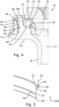
- the example of realization of figures 4 and 5 differs from the previous one on the one hand by the absence of an inner seal, and on the other hand by the structure of the outer seal 56 , of which the junction zone 66 between the sealing lip 64 and the body 58 is positioned, by reference in the upward direction 200 , at a distance above the junction zone 62 between the shrinking lip 60 and the body 56 .
- the position of the bead 54 serving as a stop has also been shifted to maintain the desired clearance with the sealing and retaining lip 64 .
- the example of realization of figures 6 and 7 differs from the previous ones by the structure of the outer seal 56 .
- the shape of the sealing lip 64 which is substantially tapered, and the replacement of the static sealing heel by an elastic lip 168 resting against the annular transition face 42 .
- the hooping of the outer seal 56 on the outer hooping surface 38 is carried out by two annular hooping lips 60 , 160 arranged axially at a distance from one another.
- each of the two hooping lips 60 , 160 has a free end forming, in axial section and before hooping on the hooping surface, a sharp corner vertex 400 greater than 20°, preferably greater than 70° and less at 90°, preferably less than 80°, the vertex having, in axial section, a bisector forming an angle 500 preferably greater than 10°, preferably greater than 30° with the ascending axial direction 200 .
- a first of the two hooping lips 60 has a junction zone 62 with the body 58 of the seal, which is located at a distance below the junction zone 66 of the sealing lip 64 with the body 58 of the seal.
- the free end of the sealing lip 64 in sliding or uncertain contact with the annular skirt 46 of the cover, is located axially between a shrinking contact zone between the first lip of hooping 60 and the hooping surface 38 and a hooping contact zone between the second hooping lip 160 and the hooping surface 38 .
- the seal thus obtained has excellent characteristics in terms of the mechanical strength of the hooping.
- the molding of the gasket in a mold whose parts are movable in translation parallel to the axis of revolution of the gasket is hampered by the presence of undercut shapes.
- the alternative embodiment of the figure 8 offers a solution to this problem, by no longer providing two annular hooping lips, but two sets of several hooping lips, namely a first set constituting a first row of N first lips 60 , where N is an integer greater than or equal to 2, and preferably greater than or equal to 3, this first row having a symmetry of revolution of order N around the reference axis, and a second set constituting a second row of N second lips 160 , also having a symmetry of revolution of order N around the reference axis, and offset with respect to the first lips 60 so that there is no superposition between the first and the second lips, for example by an angle equal to 360°/(2N).
- the seal 56 , 72 is not in sliding contact with the associated annular skirt 46 , 48 under normal operating conditions, sealing being ensured in this case by the labyrinth formed between the skirt annular 46 , 48 and the area of the seal 56 , 72 which faces it directly.
- the bearing 18 can be of any type, rolling or smooth, and the guide paths 30 , 32 can be made on attached washers 22 , 24 or directly on the cover 20 and the lower support 12 .
- the annular bead 54 can be replaced by one or more stops projecting radially towards the hooping surface, these stops being distributed over the circumference of the relevant skirt 46 , 48 .
- the seal 56 , 72 is provided with a rigid annular reinforcement, in material more stiff as the lips.
Landscapes
- Engineering & Computer Science (AREA)
- General Engineering & Computer Science (AREA)
- Mechanical Engineering (AREA)
- Sealing Of Bearings (AREA)
- Vehicle Body Suspensions (AREA)
- Rolling Contact Bearings (AREA)
- Sealing With Elastic Sealing Lips (AREA)
Applications Claiming Priority (1)
| Application Number | Priority Date | Filing Date | Title |
|---|---|---|---|
| FR2110338A FR3127536B1 (fr) | 2021-09-30 | 2021-09-30 | Butée tournante de suspension pourvue d’un joint d’étanchéité et de retenue fretté |
Publications (2)
| Publication Number | Publication Date |
|---|---|
| EP4160030A1 true EP4160030A1 (de) | 2023-04-05 |
| EP4160030B1 EP4160030B1 (de) | 2024-07-10 |
Family
ID=78212366
Family Applications (1)
| Application Number | Title | Priority Date | Filing Date |
|---|---|---|---|
| EP22198892.6A Active EP4160030B1 (de) | 2021-09-30 | 2022-09-29 | Drehfederanschlag mit fret-dichtung und -rückhaltung |
Country Status (5)
| Country | Link |
|---|---|
| US (1) | US20230100010A1 (de) |
| EP (1) | EP4160030B1 (de) |
| JP (1) | JP2023051824A (de) |
| CN (1) | CN115875369A (de) |
| FR (1) | FR3127536B1 (de) |
Families Citing this family (1)
| Publication number | Priority date | Publication date | Assignee | Title |
|---|---|---|---|---|
| JP2024140610A (ja) | 2023-03-28 | 2024-10-10 | 日本碍子株式会社 | ハニカムフィルタ |
Citations (8)
| Publication number | Priority date | Publication date | Assignee | Title |
|---|---|---|---|---|
| WO2011103921A1 (en) | 2010-02-25 | 2011-09-01 | Aktiebolaget Skf | Axial thrust bearing device with a sealing ring |
| FR2989634A1 (fr) | 2012-04-23 | 2013-10-25 | Skf Ab | Dispositif de butee de suspension et jambe de force equipee d'un tel dispositif |
| DE102017125906A1 (de) * | 2017-11-07 | 2019-05-09 | Schaeffler Technologies AG & Co. KG | Federbeinlager für ein Federbein |
| DE102018110461A1 (de) * | 2018-05-02 | 2019-11-07 | Schaeffler Technologies AG & Co. KG | Federbeinlager zur Abstützung eines Federbeins und Federbein mit dem Federbeinlager |
| EP3626486A1 (de) | 2018-09-20 | 2020-03-25 | Ntn-Snr Roulements | Aufhängungsanschlag eines kraftfahrzeugs |
| EP3693625A1 (de) | 2017-10-06 | 2020-08-12 | Oiles Corporation | Gleitlager |
| WO2021018837A1 (fr) | 2019-07-29 | 2021-02-04 | Ntn-Snr Roulements | Support de butee, butee de suspension et jambe de force comprenant une telle butee |
| FR3101279A1 (fr) | 2019-09-26 | 2021-04-02 | Ntn-Snr Roulements | GARNITURE D’ÉTANCHÉITÉ DE butÉE de suspension et BUTÉE DE SUSPENSION ASSOCIÉE |
Family Cites Families (28)
| Publication number | Priority date | Publication date | Assignee | Title |
|---|---|---|---|---|
| US4400041A (en) * | 1982-01-15 | 1983-08-23 | General Motors Corporation | Unitized seal bearing assembly |
| JPS6045108U (ja) * | 1983-08-31 | 1985-03-29 | 日本精工株式会社 | ストラツト形サスペンシヨン用軸受の密封装置 |
| US4948272A (en) * | 1989-03-28 | 1990-08-14 | General Motors Corporation | Plastic housing thrust bearing with complete sealing |
| US4925323A (en) * | 1989-08-23 | 1990-05-15 | General Motors Corporation | Unitized sealed thrust bearing assembly |
| JP3521483B2 (ja) * | 1994-06-03 | 2004-04-19 | 日本精工株式会社 | ストラット用密封型スラスト軸受 |
| US5467971A (en) * | 1994-08-08 | 1995-11-21 | General Motors Corporation | Strut assembly with integral bearing and spring seat |
| DE19614649A1 (de) * | 1996-04-13 | 1997-10-16 | Fag Automobiltechnik Ag | Dichtung, insbesondere Wälzlagerdichtung |
| US6257605B1 (en) * | 1997-06-30 | 2001-07-10 | Ina Walzlager Schaeffler Ohg | Suspension strut bearing |
| US6186507B1 (en) * | 1997-09-25 | 2001-02-13 | Michael R. Oldenburg | Retrofittable severe duty seal for a shaft |
| JPH11257360A (ja) * | 1998-01-07 | 1999-09-21 | Nippon Seiko Kk | シールリング付転がり軸受及び自動車用変速機 |
| FR2779096B1 (fr) * | 1998-05-28 | 2000-12-15 | Skf France | Dispositif de butee de suspension |
| DE59801135D1 (de) * | 1998-11-12 | 2001-09-06 | Joerg Schwarzbich | Federbeinlager |
| DE10104788C2 (de) * | 2001-02-02 | 2003-06-26 | Federal Mogul Friedberg Gmbh | Gleitringdichtung mit radialer Verdrehsicherung |
| FR2829429B1 (fr) * | 2001-09-12 | 2003-12-12 | Skf Ab | Dispositif de butee de suspension |
| FR2902699B1 (fr) * | 2006-06-26 | 2010-10-22 | Skf Ab | Dispositif de butee de suspension et jambe de force. |
| FR2918138B1 (fr) * | 2007-06-29 | 2009-10-23 | Snr Roulements Sa | Butee de suspension comprenant un element d'etancheite mobile. |
| FR2928187B1 (fr) * | 2008-02-28 | 2010-04-02 | Skf Ab | Dispositif de butee de suspension et jambe de force |
| JP5334287B2 (ja) * | 2008-06-25 | 2013-11-06 | 内山工業株式会社 | ベアリングシール |
| FR2934656B1 (fr) * | 2008-08-01 | 2013-05-17 | Skf Ab | Dispositif de butee de suspension et jambe de force. |
| FR2936580B1 (fr) * | 2008-09-26 | 2013-03-22 | Skf Ab | Butee de suspension et jambe de force associee |
| FR2948739B1 (fr) * | 2009-07-29 | 2016-02-19 | Skf Ab | Dispositif de butee de suspension et jambe de force. |
| FR2973291B1 (fr) * | 2011-03-30 | 2016-01-08 | Ntn Snr Roulements | Butee de suspension a etancheite renforcee |
| US8783960B2 (en) * | 2012-10-31 | 2014-07-22 | Thai Dieng Industry Co., Ltd. | Dust-proof housing device for an assembly and bearing assembly including the same |
| EP3002137B1 (de) * | 2014-09-30 | 2018-12-26 | Aktiebolaget SKF | Hängelagervorrichtung, Motorfahrzeug mit einer solchen Hängelagervorrichtung und Herstellungsverfahren |
| US9618045B1 (en) * | 2015-11-18 | 2017-04-11 | Schaeffler Technologies AG & Co. KG | Strut bearing |
| FR3075103B1 (fr) * | 2017-12-20 | 2019-11-22 | Aktiebolaget Skf | Dispositif de butee de suspension et jambe de force equipee d’un tel dispositif |
| DE102021105500A1 (de) * | 2021-03-08 | 2022-09-08 | Carl Freudenberg Kg | Dichtring |
| JP7719443B2 (ja) * | 2021-10-22 | 2025-08-06 | 中西金属工業株式会社 | ストラットベアリング装置、及び車両のストラット式サスペンション |
-
2021
- 2021-09-30 FR FR2110338A patent/FR3127536B1/fr active Active
-
2022
- 2022-09-27 JP JP2022154118A patent/JP2023051824A/ja active Pending
- 2022-09-27 US US17/935,583 patent/US20230100010A1/en active Pending
- 2022-09-29 EP EP22198892.6A patent/EP4160030B1/de active Active
- 2022-09-30 CN CN202211217684.1A patent/CN115875369A/zh active Pending
Patent Citations (8)
| Publication number | Priority date | Publication date | Assignee | Title |
|---|---|---|---|---|
| WO2011103921A1 (en) | 2010-02-25 | 2011-09-01 | Aktiebolaget Skf | Axial thrust bearing device with a sealing ring |
| FR2989634A1 (fr) | 2012-04-23 | 2013-10-25 | Skf Ab | Dispositif de butee de suspension et jambe de force equipee d'un tel dispositif |
| EP3693625A1 (de) | 2017-10-06 | 2020-08-12 | Oiles Corporation | Gleitlager |
| DE102017125906A1 (de) * | 2017-11-07 | 2019-05-09 | Schaeffler Technologies AG & Co. KG | Federbeinlager für ein Federbein |
| DE102018110461A1 (de) * | 2018-05-02 | 2019-11-07 | Schaeffler Technologies AG & Co. KG | Federbeinlager zur Abstützung eines Federbeins und Federbein mit dem Federbeinlager |
| EP3626486A1 (de) | 2018-09-20 | 2020-03-25 | Ntn-Snr Roulements | Aufhängungsanschlag eines kraftfahrzeugs |
| WO2021018837A1 (fr) | 2019-07-29 | 2021-02-04 | Ntn-Snr Roulements | Support de butee, butee de suspension et jambe de force comprenant une telle butee |
| FR3101279A1 (fr) | 2019-09-26 | 2021-04-02 | Ntn-Snr Roulements | GARNITURE D’ÉTANCHÉITÉ DE butÉE de suspension et BUTÉE DE SUSPENSION ASSOCIÉE |
Also Published As
| Publication number | Publication date |
|---|---|
| CN115875369A (zh) | 2023-03-31 |
| FR3127536A1 (fr) | 2023-03-31 |
| US20230100010A1 (en) | 2023-03-30 |
| EP4160030B1 (de) | 2024-07-10 |
| FR3127536B1 (fr) | 2023-12-08 |
| JP2023051824A (ja) | 2023-04-11 |
Similar Documents
| Publication | Publication Date | Title |
|---|---|---|
| EP3027440B1 (de) | Axialwälzlager für eine fahrzeugaufhängung | |
| EP1555144B1 (de) | Axialwälzlager für eine Aufhängung | |
| FR2934656A1 (fr) | Dispositif de butee de suspension et jambe de force. | |
| FR2936580A1 (fr) | Butee de suspension et jambe de force associee | |
| EP1243446B1 (de) | Axialwälzlager für eine Fahrzeugaufhängung mit Rückhaltemittel | |
| FR2928187A1 (fr) | Dispositif de butee de suspension et jambe de force | |
| FR2948066A1 (fr) | Dispositif de butee de suspension et jambe de force. | |
| FR2961439A1 (fr) | Dispositif de butee de suspension | |
| FR3075103A1 (fr) | Dispositif de butee de suspension et jambe de force equipee d’un tel dispositif | |
| FR2965028A1 (fr) | Dispositif de butee de suspension | |
| EP0057348B1 (de) | Schrägwälzlager mit zwei Reihen Wälzkörper und Verfahren zum Zusammenbau | |
| EP3219521B1 (de) | Anschlagpuffer mit axial gepresster monoblockschale | |
| EP4160030B1 (de) | Drehfederanschlag mit fret-dichtung und -rückhaltung | |
| EP0561704B1 (de) | Axialwälzlager für Fahrzeugaufhängung und sein Montageverfahren | |
| WO2021018837A1 (fr) | Support de butee, butee de suspension et jambe de force comprenant une telle butee | |
| FR3101279A1 (fr) | GARNITURE D’ÉTANCHÉITÉ DE butÉE de suspension et BUTÉE DE SUSPENSION ASSOCIÉE | |
| FR3039600A1 (fr) | Assemblage de roulement | |
| FR2966086A1 (fr) | Dispositif de butee de suspension | |
| FR2910944A1 (fr) | Butee de suspension a roulement, cage de roulement et garniture d'etancheite | |
| FR2984978A1 (fr) | Procede de fabrication d'un roulement, roulement et dispositif rotatif comportant un tel roulement | |
| FR2925943A1 (fr) | Assemblage pour roulement a rouleaux coniques et son procede de fabrication | |
| FR3029245A1 (fr) | Piece et systeme d'etancheite pour roulements, et roulement muni de tels pieces et systemes | |
| FR2966087A1 (fr) | Dispositif de butee de suspension | |
| EP4607049A1 (de) | Drehfederanschlag mit eingebauter dichtung | |
| FR2966084A1 (fr) | Dispositif de butee de suspension |
Legal Events
| Date | Code | Title | Description |
|---|---|---|---|
| PUAI | Public reference made under article 153(3) epc to a published international application that has entered the european phase |
Free format text: ORIGINAL CODE: 0009012 |
|
| STAA | Information on the status of an ep patent application or granted ep patent |
Free format text: STATUS: THE APPLICATION HAS BEEN PUBLISHED |
|
| STAA | Information on the status of an ep patent application or granted ep patent |
Free format text: STATUS: REQUEST FOR EXAMINATION WAS MADE |
|
| AK | Designated contracting states |
Kind code of ref document: A1 Designated state(s): AL AT BE BG CH CY CZ DE DK EE ES FI FR GB GR HR HU IE IS IT LI LT LU LV MC MK MT NL NO PL PT RO RS SE SI SK SM TR |
|
| 17P | Request for examination filed |
Effective date: 20230328 |
|
| RBV | Designated contracting states (corrected) |
Designated state(s): AL AT BE BG CH CY CZ DE DK EE ES FI FR GB GR HR HU IE IS IT LI LT LU LV MC MK MT NL NO PL PT RO RS SE SI SK SM TR |
|
| RAP3 | Party data changed (applicant data changed or rights of an application transferred) |
Owner name: NTN EUROPE |
|
| GRAP | Despatch of communication of intention to grant a patent |
Free format text: ORIGINAL CODE: EPIDOSNIGR1 |
|
| STAA | Information on the status of an ep patent application or granted ep patent |
Free format text: STATUS: GRANT OF PATENT IS INTENDED |
|
| RIC1 | Information provided on ipc code assigned before grant |
Ipc: B60G 15/06 20060101ALI20240220BHEP Ipc: F16C 33/78 20060101ALI20240220BHEP Ipc: F16C 19/10 20060101AFI20240220BHEP |
|
| INTG | Intention to grant announced |
Effective date: 20240325 |
|
| GRAS | Grant fee paid |
Free format text: ORIGINAL CODE: EPIDOSNIGR3 |
|
| GRAA | (expected) grant |
Free format text: ORIGINAL CODE: 0009210 |
|
| STAA | Information on the status of an ep patent application or granted ep patent |
Free format text: STATUS: THE PATENT HAS BEEN GRANTED |
|
| AK | Designated contracting states |
Kind code of ref document: B1 Designated state(s): AL AT BE BG CH CY CZ DE DK EE ES FI FR GB GR HR HU IE IS IT LI LT LU LV MC MK MT NL NO PL PT RO RS SE SI SK SM TR |
|
| REG | Reference to a national code |
Ref country code: CH Ref legal event code: EP |
|
| REG | Reference to a national code |
Ref country code: DE Ref legal event code: R096 Ref document number: 602022004461 Country of ref document: DE |
|
| P01 | Opt-out of the competence of the unified patent court (upc) registered |
Free format text: CASE NUMBER: APP_42425/2024 Effective date: 20240718 |
|
| REG | Reference to a national code |
Ref country code: LT Ref legal event code: MG9D |
|
| REG | Reference to a national code |
Ref country code: NL Ref legal event code: MP Effective date: 20240710 |
|
| PG25 | Lapsed in a contracting state [announced via postgrant information from national office to epo] |
Ref country code: PT Free format text: LAPSE BECAUSE OF FAILURE TO SUBMIT A TRANSLATION OF THE DESCRIPTION OR TO PAY THE FEE WITHIN THE PRESCRIBED TIME-LIMIT Effective date: 20241111 |
|
| REG | Reference to a national code |
Ref country code: AT Ref legal event code: MK05 Ref document number: 1702258 Country of ref document: AT Kind code of ref document: T Effective date: 20240710 |
|
| PG25 | Lapsed in a contracting state [announced via postgrant information from national office to epo] |
Ref country code: NL Free format text: LAPSE BECAUSE OF FAILURE TO SUBMIT A TRANSLATION OF THE DESCRIPTION OR TO PAY THE FEE WITHIN THE PRESCRIBED TIME-LIMIT Effective date: 20240710 |
|
| PG25 | Lapsed in a contracting state [announced via postgrant information from national office to epo] |
Ref country code: PT Free format text: LAPSE BECAUSE OF FAILURE TO SUBMIT A TRANSLATION OF THE DESCRIPTION OR TO PAY THE FEE WITHIN THE PRESCRIBED TIME-LIMIT Effective date: 20241111 Ref country code: NL Free format text: LAPSE BECAUSE OF FAILURE TO SUBMIT A TRANSLATION OF THE DESCRIPTION OR TO PAY THE FEE WITHIN THE PRESCRIBED TIME-LIMIT Effective date: 20240710 |
|
| PG25 | Lapsed in a contracting state [announced via postgrant information from national office to epo] |
Ref country code: NO Free format text: LAPSE BECAUSE OF FAILURE TO SUBMIT A TRANSLATION OF THE DESCRIPTION OR TO PAY THE FEE WITHIN THE PRESCRIBED TIME-LIMIT Effective date: 20241010 |
|
| PG25 | Lapsed in a contracting state [announced via postgrant information from national office to epo] |
Ref country code: GR Free format text: LAPSE BECAUSE OF FAILURE TO SUBMIT A TRANSLATION OF THE DESCRIPTION OR TO PAY THE FEE WITHIN THE PRESCRIBED TIME-LIMIT Effective date: 20241011 Ref country code: PL Free format text: LAPSE BECAUSE OF FAILURE TO SUBMIT A TRANSLATION OF THE DESCRIPTION OR TO PAY THE FEE WITHIN THE PRESCRIBED TIME-LIMIT Effective date: 20240710 Ref country code: FI Free format text: LAPSE BECAUSE OF FAILURE TO SUBMIT A TRANSLATION OF THE DESCRIPTION OR TO PAY THE FEE WITHIN THE PRESCRIBED TIME-LIMIT Effective date: 20240710 |
|
| PG25 | Lapsed in a contracting state [announced via postgrant information from national office to epo] |
Ref country code: BG Free format text: LAPSE BECAUSE OF FAILURE TO SUBMIT A TRANSLATION OF THE DESCRIPTION OR TO PAY THE FEE WITHIN THE PRESCRIBED TIME-LIMIT Effective date: 20240710 |
|
| PG25 | Lapsed in a contracting state [announced via postgrant information from national office to epo] |
Ref country code: LV Free format text: LAPSE BECAUSE OF FAILURE TO SUBMIT A TRANSLATION OF THE DESCRIPTION OR TO PAY THE FEE WITHIN THE PRESCRIBED TIME-LIMIT Effective date: 20240710 |
|
| PG25 | Lapsed in a contracting state [announced via postgrant information from national office to epo] |
Ref country code: IS Free format text: LAPSE BECAUSE OF FAILURE TO SUBMIT A TRANSLATION OF THE DESCRIPTION OR TO PAY THE FEE WITHIN THE PRESCRIBED TIME-LIMIT Effective date: 20241110 Ref country code: AT Free format text: LAPSE BECAUSE OF FAILURE TO SUBMIT A TRANSLATION OF THE DESCRIPTION OR TO PAY THE FEE WITHIN THE PRESCRIBED TIME-LIMIT Effective date: 20240710 |
|
| PG25 | Lapsed in a contracting state [announced via postgrant information from national office to epo] |
Ref country code: HR Free format text: LAPSE BECAUSE OF FAILURE TO SUBMIT A TRANSLATION OF THE DESCRIPTION OR TO PAY THE FEE WITHIN THE PRESCRIBED TIME-LIMIT Effective date: 20240710 |
|
| PG25 | Lapsed in a contracting state [announced via postgrant information from national office to epo] |
Ref country code: ES Free format text: LAPSE BECAUSE OF FAILURE TO SUBMIT A TRANSLATION OF THE DESCRIPTION OR TO PAY THE FEE WITHIN THE PRESCRIBED TIME-LIMIT Effective date: 20240710 Ref country code: RS Free format text: LAPSE BECAUSE OF FAILURE TO SUBMIT A TRANSLATION OF THE DESCRIPTION OR TO PAY THE FEE WITHIN THE PRESCRIBED TIME-LIMIT Effective date: 20241010 |
|
| PG25 | Lapsed in a contracting state [announced via postgrant information from national office to epo] |
Ref country code: RS Free format text: LAPSE BECAUSE OF FAILURE TO SUBMIT A TRANSLATION OF THE DESCRIPTION OR TO PAY THE FEE WITHIN THE PRESCRIBED TIME-LIMIT Effective date: 20241010 Ref country code: PL Free format text: LAPSE BECAUSE OF FAILURE TO SUBMIT A TRANSLATION OF THE DESCRIPTION OR TO PAY THE FEE WITHIN THE PRESCRIBED TIME-LIMIT Effective date: 20240710 Ref country code: NO Free format text: LAPSE BECAUSE OF FAILURE TO SUBMIT A TRANSLATION OF THE DESCRIPTION OR TO PAY THE FEE WITHIN THE PRESCRIBED TIME-LIMIT Effective date: 20241010 Ref country code: LV Free format text: LAPSE BECAUSE OF FAILURE TO SUBMIT A TRANSLATION OF THE DESCRIPTION OR TO PAY THE FEE WITHIN THE PRESCRIBED TIME-LIMIT Effective date: 20240710 Ref country code: IS Free format text: LAPSE BECAUSE OF FAILURE TO SUBMIT A TRANSLATION OF THE DESCRIPTION OR TO PAY THE FEE WITHIN THE PRESCRIBED TIME-LIMIT Effective date: 20241110 Ref country code: HR Free format text: LAPSE BECAUSE OF FAILURE TO SUBMIT A TRANSLATION OF THE DESCRIPTION OR TO PAY THE FEE WITHIN THE PRESCRIBED TIME-LIMIT Effective date: 20240710 Ref country code: GR Free format text: LAPSE BECAUSE OF FAILURE TO SUBMIT A TRANSLATION OF THE DESCRIPTION OR TO PAY THE FEE WITHIN THE PRESCRIBED TIME-LIMIT Effective date: 20241011 Ref country code: FI Free format text: LAPSE BECAUSE OF FAILURE TO SUBMIT A TRANSLATION OF THE DESCRIPTION OR TO PAY THE FEE WITHIN THE PRESCRIBED TIME-LIMIT Effective date: 20240710 Ref country code: ES Free format text: LAPSE BECAUSE OF FAILURE TO SUBMIT A TRANSLATION OF THE DESCRIPTION OR TO PAY THE FEE WITHIN THE PRESCRIBED TIME-LIMIT Effective date: 20240710 Ref country code: BG Free format text: LAPSE BECAUSE OF FAILURE TO SUBMIT A TRANSLATION OF THE DESCRIPTION OR TO PAY THE FEE WITHIN THE PRESCRIBED TIME-LIMIT Effective date: 20240710 Ref country code: AT Free format text: LAPSE BECAUSE OF FAILURE TO SUBMIT A TRANSLATION OF THE DESCRIPTION OR TO PAY THE FEE WITHIN THE PRESCRIBED TIME-LIMIT Effective date: 20240710 |
|
| REG | Reference to a national code |
Ref country code: DE Ref legal event code: R097 Ref document number: 602022004461 Country of ref document: DE |
|
| PG25 | Lapsed in a contracting state [announced via postgrant information from national office to epo] |
Ref country code: RO Free format text: LAPSE BECAUSE OF FAILURE TO SUBMIT A TRANSLATION OF THE DESCRIPTION OR TO PAY THE FEE WITHIN THE PRESCRIBED TIME-LIMIT Effective date: 20240710 Ref country code: SM Free format text: LAPSE BECAUSE OF FAILURE TO SUBMIT A TRANSLATION OF THE DESCRIPTION OR TO PAY THE FEE WITHIN THE PRESCRIBED TIME-LIMIT Effective date: 20240710 Ref country code: DK Free format text: LAPSE BECAUSE OF FAILURE TO SUBMIT A TRANSLATION OF THE DESCRIPTION OR TO PAY THE FEE WITHIN THE PRESCRIBED TIME-LIMIT Effective date: 20240710 |
|
| PG25 | Lapsed in a contracting state [announced via postgrant information from national office to epo] |
Ref country code: MC Free format text: LAPSE BECAUSE OF FAILURE TO SUBMIT A TRANSLATION OF THE DESCRIPTION OR TO PAY THE FEE WITHIN THE PRESCRIBED TIME-LIMIT Effective date: 20240710 Ref country code: EE Free format text: LAPSE BECAUSE OF FAILURE TO SUBMIT A TRANSLATION OF THE DESCRIPTION OR TO PAY THE FEE WITHIN THE PRESCRIBED TIME-LIMIT Effective date: 20240710 |
|
| PG25 | Lapsed in a contracting state [announced via postgrant information from national office to epo] |
Ref country code: CZ Free format text: LAPSE BECAUSE OF FAILURE TO SUBMIT A TRANSLATION OF THE DESCRIPTION OR TO PAY THE FEE WITHIN THE PRESCRIBED TIME-LIMIT Effective date: 20240710 |
|
| PG25 | Lapsed in a contracting state [announced via postgrant information from national office to epo] |
Ref country code: SK Free format text: LAPSE BECAUSE OF FAILURE TO SUBMIT A TRANSLATION OF THE DESCRIPTION OR TO PAY THE FEE WITHIN THE PRESCRIBED TIME-LIMIT Effective date: 20240710 Ref country code: IT Free format text: LAPSE BECAUSE OF FAILURE TO SUBMIT A TRANSLATION OF THE DESCRIPTION OR TO PAY THE FEE WITHIN THE PRESCRIBED TIME-LIMIT Effective date: 20240710 |
|
| PLBE | No opposition filed within time limit |
Free format text: ORIGINAL CODE: 0009261 |
|
| STAA | Information on the status of an ep patent application or granted ep patent |
Free format text: STATUS: NO OPPOSITION FILED WITHIN TIME LIMIT |
|
| PG25 | Lapsed in a contracting state [announced via postgrant information from national office to epo] |
Ref country code: LU Free format text: LAPSE BECAUSE OF NON-PAYMENT OF DUE FEES Effective date: 20240929 |
|
| 26N | No opposition filed |
Effective date: 20250411 |
|
| REG | Reference to a national code |
Ref country code: BE Ref legal event code: MM Effective date: 20240930 |
|
| PG25 | Lapsed in a contracting state [announced via postgrant information from national office to epo] |
Ref country code: BE Free format text: LAPSE BECAUSE OF NON-PAYMENT OF DUE FEES Effective date: 20240930 |
|
| PG25 | Lapsed in a contracting state [announced via postgrant information from national office to epo] |
Ref country code: IE Free format text: LAPSE BECAUSE OF NON-PAYMENT OF DUE FEES Effective date: 20240929 |
|
| PG25 | Lapsed in a contracting state [announced via postgrant information from national office to epo] |
Ref country code: SE Free format text: LAPSE BECAUSE OF FAILURE TO SUBMIT A TRANSLATION OF THE DESCRIPTION OR TO PAY THE FEE WITHIN THE PRESCRIBED TIME-LIMIT Effective date: 20240710 |
|
| PGFP | Annual fee paid to national office [announced via postgrant information from national office to epo] |
Ref country code: DE Payment date: 20250919 Year of fee payment: 4 |
|
| PGFP | Annual fee paid to national office [announced via postgrant information from national office to epo] |
Ref country code: FR Payment date: 20250922 Year of fee payment: 4 |
|
| PG25 | Lapsed in a contracting state [announced via postgrant information from national office to epo] |
Ref country code: CY Free format text: LAPSE BECAUSE OF FAILURE TO SUBMIT A TRANSLATION OF THE DESCRIPTION OR TO PAY THE FEE WITHIN THE PRESCRIBED TIME-LIMIT; INVALID AB INITIO Effective date: 20220929 |
|
| PG25 | Lapsed in a contracting state [announced via postgrant information from national office to epo] |
Ref country code: HU Free format text: LAPSE BECAUSE OF FAILURE TO SUBMIT A TRANSLATION OF THE DESCRIPTION OR TO PAY THE FEE WITHIN THE PRESCRIBED TIME-LIMIT; INVALID AB INITIO Effective date: 20220929 |