EP4160037A1 - Accouplement de limitation de couple - Google Patents
Accouplement de limitation de couple Download PDFInfo
- Publication number
- EP4160037A1 EP4160037A1 EP21199694.7A EP21199694A EP4160037A1 EP 4160037 A1 EP4160037 A1 EP 4160037A1 EP 21199694 A EP21199694 A EP 21199694A EP 4160037 A1 EP4160037 A1 EP 4160037A1
- Authority
- EP
- European Patent Office
- Prior art keywords
- shaft
- coupling
- torque
- coupling ring
- shear
- Prior art date
- Legal status (The legal status is an assumption and is not a legal conclusion. Google has not performed a legal analysis and makes no representation as to the accuracy of the status listed.)
- Granted
Links
Images
Classifications
-
- F—MECHANICAL ENGINEERING; LIGHTING; HEATING; WEAPONS; BLASTING
- F16—ENGINEERING ELEMENTS AND UNITS; GENERAL MEASURES FOR PRODUCING AND MAINTAINING EFFECTIVE FUNCTIONING OF MACHINES OR INSTALLATIONS; THERMAL INSULATION IN GENERAL
- F16D—COUPLINGS FOR TRANSMITTING ROTATION; CLUTCHES; BRAKES
- F16D1/00—Couplings for rigidly connecting two coaxial shafts or other movable machine elements
- F16D1/06—Couplings for rigidly connecting two coaxial shafts or other movable machine elements for attachment of a member on a shaft or on a shaft-end
- F16D1/08—Couplings for rigidly connecting two coaxial shafts or other movable machine elements for attachment of a member on a shaft or on a shaft-end with clamping hub; with hub and longitudinal key
- F16D1/0805—Couplings for rigidly connecting two coaxial shafts or other movable machine elements for attachment of a member on a shaft or on a shaft-end with clamping hub; with hub and longitudinal key with radial clamping due to deformation of a resilient body or a body of fluid
-
- F—MECHANICAL ENGINEERING; LIGHTING; HEATING; WEAPONS; BLASTING
- F16—ENGINEERING ELEMENTS AND UNITS; GENERAL MEASURES FOR PRODUCING AND MAINTAINING EFFECTIVE FUNCTIONING OF MACHINES OR INSTALLATIONS; THERMAL INSULATION IN GENERAL
- F16D—COUPLINGS FOR TRANSMITTING ROTATION; CLUTCHES; BRAKES
- F16D1/00—Couplings for rigidly connecting two coaxial shafts or other movable machine elements
- F16D1/06—Couplings for rigidly connecting two coaxial shafts or other movable machine elements for attachment of a member on a shaft or on a shaft-end
- F16D1/08—Couplings for rigidly connecting two coaxial shafts or other movable machine elements for attachment of a member on a shaft or on a shaft-end with clamping hub; with hub and longitudinal key
- F16D1/09—Couplings for rigidly connecting two coaxial shafts or other movable machine elements for attachment of a member on a shaft or on a shaft-end with clamping hub; with hub and longitudinal key with radial clamping due to axial loading of at least one pair of conical surfaces
- F16D1/092—Couplings for rigidly connecting two coaxial shafts or other movable machine elements for attachment of a member on a shaft or on a shaft-end with clamping hub; with hub and longitudinal key with radial clamping due to axial loading of at least one pair of conical surfaces the pair of conical mating surfaces being provided on the coupled hub and shaft
-
- F—MECHANICAL ENGINEERING; LIGHTING; HEATING; WEAPONS; BLASTING
- F16—ENGINEERING ELEMENTS AND UNITS; GENERAL MEASURES FOR PRODUCING AND MAINTAINING EFFECTIVE FUNCTIONING OF MACHINES OR INSTALLATIONS; THERMAL INSULATION IN GENERAL
- F16D—COUPLINGS FOR TRANSMITTING ROTATION; CLUTCHES; BRAKES
- F16D7/00—Slip couplings, e.g. slipping on overload, for absorbing shock
- F16D7/02—Slip couplings, e.g. slipping on overload, for absorbing shock of the friction type
- F16D7/021—Slip couplings, e.g. slipping on overload, for absorbing shock of the friction type with radially applied torque-limiting friction surfaces
-
- F—MECHANICAL ENGINEERING; LIGHTING; HEATING; WEAPONS; BLASTING
- F16—ENGINEERING ELEMENTS AND UNITS; GENERAL MEASURES FOR PRODUCING AND MAINTAINING EFFECTIVE FUNCTIONING OF MACHINES OR INSTALLATIONS; THERMAL INSULATION IN GENERAL
- F16D—COUPLINGS FOR TRANSMITTING ROTATION; CLUTCHES; BRAKES
- F16D9/00—Couplings with safety member for disconnecting, e.g. breaking or melting member
- F16D9/06—Couplings with safety member for disconnecting, e.g. breaking or melting member by breaking due to shear stress
-
- Y—GENERAL TAGGING OF NEW TECHNOLOGICAL DEVELOPMENTS; GENERAL TAGGING OF CROSS-SECTIONAL TECHNOLOGIES SPANNING OVER SEVERAL SECTIONS OF THE IPC; TECHNICAL SUBJECTS COVERED BY FORMER USPC CROSS-REFERENCE ART COLLECTIONS [XRACs] AND DIGESTS
- Y10—TECHNICAL SUBJECTS COVERED BY FORMER USPC
- Y10T—TECHNICAL SUBJECTS COVERED BY FORMER US CLASSIFICATION
- Y10T403/00—Joints and connections
- Y10T403/22—Joints and connections with fluid pressure responsive component
-
- Y—GENERAL TAGGING OF NEW TECHNOLOGICAL DEVELOPMENTS; GENERAL TAGGING OF CROSS-SECTIONAL TECHNOLOGIES SPANNING OVER SEVERAL SECTIONS OF THE IPC; TECHNICAL SUBJECTS COVERED BY FORMER USPC CROSS-REFERENCE ART COLLECTIONS [XRACs] AND DIGESTS
- Y10—TECHNICAL SUBJECTS COVERED BY FORMER USPC
- Y10T—TECHNICAL SUBJECTS COVERED BY FORMER US CLASSIFICATION
- Y10T403/00—Joints and connections
- Y10T403/76—Joints and connections having a cam, wedge, or tapered portion
Definitions
- the present invention relates to a torque limiting coupling comprising a first shaft, a shear plate fixedly connected with the first shaft and a coupling ring arranged coaxially to the first shaft, where the coupling ring comprises a lateral surface which is in contact with a lateral surface of the first shaft, where the coupling ring has a double-walled section with an internal annular pressure fluid chamber, designed in such a way, that this section increases its radial thickness when the fluid chamber is filled with pressurized fluid and thereby increases the pressure forces and the friction forces between the lateral surfaces of the coupling ring and the first shaft in order to allow torque transfer.
- the coupling ring transfers no torque anymore, because the lateral contact surface of the coupling ring can rotate relatively to the lateral surface of the first shaft due to no or reduced friction forces.
- the coupling ring comprises furthermore a shear tube closing the pressurized fluid chamber to hold the pressure, whereby the shear plate is designed to cut off a tip of the shear tube in order to open the pressure fluid chamber if the first shaft is slipping relatively to the coupling ring, which is the case, when the torque is higher than a predefined maximum transferable torque given by the fluid pressure and the design of the coupling.
- the pressure fluid chamber is opened and the fluid pressure is relieved.
- the surface pressure between the lateral surface of the coupling ring and the first shaft is reduced and no torque is transferred.
- the coupling After refilling the pressure fluid chamber with pressurized fluid and closing the opening, for example with a new shear tube, the coupling is reset and again transfers torque between first shaft and coupling ring.
- Such torque limiting couplings are known in prior art for example disclosed in US 4,264,229 as shown in the embodiment according to figure 5. These couplings are often used as safety couplings to protect a drive train from overload. That is especially important for drive trains where a blockage could occur at the load side.
- These couplings comprises a coupling ring and the thickness of the coupling ring can be increased by a pressurized fluid chamber within that ring. So sufficient contact pressure is created for transferring torque. Once the fluid pressure is relieved, the contact pressure and with that the friction forces are low, torque transfer is no longer possible. The shaft and the coupling ring rotate relatively to each other.
- the torque limiting couplings need to provide a high reliability, should take not too much space for installation and should be easily refillable after release of the coupling. These are in many applications diverging demands.
- the correct assembly is very difficult and critical regarding functionality. It needs to become easier and less sensitive to failures.
- the task of the invention is an improvement of the torque limiting coupling by saving space for installation, increasing reliability and allowing an easier assembly, as well as a reduction of costs in order to overcome the above mentioned problems.
- the inventive torque limiting coupling is characterized in that the first shaft comprises a conical connector and that the shear plate is fixed by one central bolt to the first shaft, by pressing a conical bushing, which is connected to or part of the shear plate, against the conical connector.
- the shear plate is reliably connected to the first shaft with low space demand for installation.
- the conical connector and the appropriate conical bushing of the shear plate provides a high friction force between the first shaft and the shear plate even at a quite low tightening torque of the bolt. That allows to use a smaller bolt, which on one hand saves space for the components and on the other hand gives the possibility to use smaller tools for assembly. In many cases not only space for the components itself is limited but also space for handling the tools during assembly. Furthermore the assembly is easier and faster.
- a further advantage of this solution is the better access for refilling after release of the coupling.
- the shear tube After the release of the coupling the shear tube is cut off and needs to be replaced.
- the shear plate blocks access to the bore of the shear tube.
- the shear plate is fixed to the first shaft by only one central bolt for fastening. That allows always to bring a recess of the shear plate over the position of the shear tube just by loosen the bolt and rotating only the shear plate independently to the first shaft. After replacing the shear tube the shear plate can be fixed in any angular position. So the refilling and the reset of the coupling can happen with minimum effort.
- the conical connection between first shaft and shear plate can be a conical connector like a pin at the first shaft and a conical bushing with an appropriate cavity. Or vice versa with a conical bushing forming a conical pin and a conical connector formed as an appropriate conical cavity in the first shaft.
- a preferred pressure fluid for the coupling is oil or any other fluid suitable for this function.
- the shear plate comprises at least two recesses each with a shear edge suitable to cut off the shear tube. An improved balancing is achieved with two recesses in opposite position.
- the shear plate comprises at least one recess, especially preferred at least two recesses, giving an open area with an opening angle ⁇ with reference to the axis of at least 20°, preferred of at least 40°.
- the access to the coupling ring is further improved, especially for access to the shear tube and simultaneously to the pressure fluid port.
- the balancing is improved.
- the conical connector has an angle of the taper ⁇ of more than 6°, preferred of more than 12°.
- the angle ⁇ it is avoidable that the conical connection becomes self-retaining.
- the limit for self-retaining is region of 5° or up to 11°.
- the conical connector has the conical connector an angle of the taper ⁇ of less than 35°, preferred of less than 25°. With such an upper limit for the angle ⁇ the pressing effect in the conical connection can be optimized. The required strength for the connection can be reached even with lower bolt preload, so that a smaller bolt and a moderate tightening torque can be used.
- a further preferred embodiment is a torque limiting coupling comprising additionally a second shaft which is connected to the coupling ring, where the coupling ring comprises a coupling sleeve which is arranged in radial direction (R) between the first shaft and the second shaft, and where the coupling sleeve is the double-walled section with the internal annular pressure fluid chamber.
- the coupling sleeve transfers the torque between the lateral surfaces of the first shaft and the second shaft.
- the second shaft is preferred formed by a hollow shaft. The advantage is that the coupling ring is a separate component. First and second shaft can be part of the drive side or the load side of the drive train.
- the length L of the coupling sleeve is between 50 mm and 250 mm, preferred between 80 mm and 180 mm. With that length there is on the one hand enough contact area for the torque transfer and on the other hand enough length for adjustment of the position of the second shaft. As the length L is considered the length of the outer surface in longitudinal direction where the coupling sleeve is in contact with the second shaft.
- the thickness t of the coupling sleeve is between 10 mm and 30 mm.
- the mechanical properties such as diameter, length and thickness of the coupling sleeve as well as the fluid pressure.
- the coupling comprises a first roller bearing between the first shaft and the second shaft or between the first shaft and the coupling ring, and that it comprises a second roller bearing between the first shaft and the coupling ring.
- the second shaft is a hollow shaft of a rotor of an electric motor. Due to the improved possibilities for adjustment of the second shaft it is possible to directly include the hollow shaft of a rotor in the torque limiting coupling.
- the first shaft is formed by the driven shaft of an electric motor to be connected to a load or a gear.
- That feature allows an integration of the torque limiting coupling in an electric motor and saves installation space in applications.
- the torque limiting coupling is designed to be used in the main drive train of a tunnel boring machine, especially in an electric motor of the main drive. Particularly in tunnel boring machines it is important to protect the drive train reliable against overload. But it is also necessary to save space for installation and simplifies the assembly.
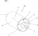
- the torque limiting coupling 20a comprises the first shaft 1, the coupling ring 3a and the shear plate 9 tightly connected to the first shaft 1 with a central bolt 11.
- the coupling ring 3a is positioned concentric to the first shaft 1 with its axis 19.
- the central bolt 11 presses the conical bushing 10 onto the not visible conical connector 1.1 of the first shaft 1.
- the shear plate 9 comprises several recesses 18 each with a shear edge 15.
- the first shaft 1 slips relatively to the coupling ring 3a.
- the shear plate 9 tightly connected to the first shaft 1 cuts off the tip of the shear tube 8 by one of the shear edges 15.
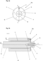
- Fig.2a shows the front view of the torque limiting coupling 20a.
- the shear tube 8 For refilling after release of the coupling the shear tube 8 needs to be replaced by a new one. And therefore, access to the bore of the shear tube 8 is necessary.
- the shear plate 9 becomes rotatable and can be adjusted in any angular position.
- the shear plate is fixed by tightening the central bolt 11.
- Fig.2b a sectional view along A-A is shown.
- the first shaft 1 is connected to a load 21, and the coupling ring 3a is connected to a drive or motor 22.
- the shear tube 8 is cut off by the shear plate 9.
- the fluid flows through the pressure fluid channel 7 out of the pressure fluid chamber 6 and thus the contact pressure between first shaft 1 and coupling ring 3a is reduced. No torque transfer takes place anymore.
- the coupling 20a is released.
- the sectional view shows the conical connector 1.1 of the first shaft with the central bore 5 for the bolt 11 and the conical bushing 10 of the shear plate 9.
- the conical bushing 10 and the shear plate 9 are made in one piece. Alternatively, they can be made as two parts tightly connected. Due to the tightening torque of the central bolt 11 the conical connection 1.1,10 is pressed together to build up a torque-proof connection between shear plate 9 and first shaft 1.
- the transferable torque in that conical connection needs to be significantly higher than the transferable torque in the coupling and high enough to cut off the shear tube 8 reliably.
- the lower limit for the cone angle ⁇ preferred at least 6°, especially at least 12°.
- the inventive solution can also be realized with a conical connection where the conical bushing is forming a conical pin and the conical connector is formed as an appropriate conical cavity in the first shaft.
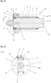
- Fig.3a and 3b show a preferred embodiment for the torque limiting coupling 20 according to the invention with the first shaft 1 and the second shaft 2 and the coupling ring 3 as a separate component.
- the first shaft 1 is connected or is designed to be connected to a load 21.
- the coupling ring 3 is mounted on the cylindrical surface of the first shaft 1.
- the coupling ring 3 comprises a connection flange and the coupling sleeve 4.
- the coupling sleeve 4 is positioned in radial direction R between the first shaft 1 and the second shaft 2.
- the second shaft 2 is designed as hollow shaft or as hub. It is connected or is designed to be connected to a drive 22, for example to the rotor of an electric motor.
- the coupling sleeve 4 has an inner surface, which is in contact with the cylindrical surface of the first shaft 1, and an outer surface, which is in areal contact with the second shaft 2.
- the coupling sleeve 4 includes the pressure fluid chamber 6, which is designed as a narrow annular gap. If this pressure fluid chamber 6 is filled with pressurized fluid the thickness of the sleeve 4 increases and creates the desired contact pressure for the torque transmission between the first shaft 1, the coupling ring 3 and the second shaft 2. If the fluid pressure is relieved there is no torque transmission and the coupling ring 3 slips at the inner surface relatively to the first shaft 1. The torque limiting coupling is released by relieving the fluid pressure.
- the shear tube 8 closes the pressure fluid channel 7 and the pressure fluid chamber 6 to maintain the fluid pressure and with it the contact pressure and the ability to transfer torque.
- the shear tube has a dedicated tip with a breaking point. If the tip is cut off, the pressure fluid channel 7 is open to the ambient, the fluid pressure is relieved and no torque will be transferred over the coupling ring 3.
- roller bearings 13,14 For a reliable rotation in case of release of the coupling there are two roller bearings 13,14 to stabilize the two shafts 1,2.
- the first roller bearing 14 could be also be positioned between the first shaft 1 and the coupling ring 3.
- Preferred one or both roller bearings 13,14 are designed as ball bearings.
- the roller bearings can be design for example as needle bearings or conical roller bearings or as any other type of roller bearings.
- the shear ring 9 is connected to the first shaft 1 by one central bolt 11.
- the first shaft 1 comprises a conical connector 1.1 formed like a pin and the shear plate 9 comprises a conical bushing 10.
- the distance ring 12 allows a uniform force application into the bushing 10 and for the bolt 11.
- the Fig.3a shows a sectional view of the torque limiting coupling 20 along the axis 19.
- Fig.3b the front view along the line B-B of figure 1 is shown.
- the mounted shear ring 9 is connected to the first shaft by one central bolt 11.
- the shear ring 9 comprises several recesses 18 each with a shear edge 15 and is dedicated to release the coupling in case of too high torque. If the torque is higher than the maximum transferable torque of the coupling ring 3, the second shaft 2 and the coupling ring 3 slips at the inner surface relatively to the first shaft 1 and the connected shear ring 9. This leads to that the shear edge 15 of the shear ring 9 cuts off the tip of the shear tube 8 and the fluid pressure will be relieved.
- the shear plate 9 comprises two recesses 18 with enlarged open area with an opening angle ⁇ .
- the opening angle ⁇ is especially at least 20°, or preferred at least 40° to give better access to the coupling ring 3 for maintenance or refilling.
- the further recesses 18a are advantageous to give also simultaneously access to further ports or screws, like for example lubrication oil ports.
- the opposite position of the two recesses 18 and the two recesses 18a are for improved balancing of the shear plate 9.
- the first shaft 1 slips relatively to the coupling ring 3 connected with the second shaft 2.
- the shear ring 9 rotates relatively to the coupling ring 3 and cuts off the tip of the shear tube 8 and due to this the coupling is released.
- a replacement of the shear tube 8 and a refill of the pressure fluid chamber with pressurized fluid via the pressure fluid port 16 is required after the release.
- the coupling ring 3 is screwed to the second shaft 2.
- the adjustment essentially takes place in longitudinal direction to adapt to any manufacturing or assembly tolerances.
- the connection between the lateral surfaces of coupling sleeve 4 and second shaft 2 can be a tapered connection or a crimp connection.
Landscapes
- Engineering & Computer Science (AREA)
- General Engineering & Computer Science (AREA)
- Mechanical Engineering (AREA)
- Physics & Mathematics (AREA)
- Fluid Mechanics (AREA)
- Clamps And Clips (AREA)
- One-Way And Automatic Clutches, And Combinations Of Different Clutches (AREA)
Priority Applications (5)
| Application Number | Priority Date | Filing Date | Title |
|---|---|---|---|
| EP21199694.7A EP4160037B1 (fr) | 2021-09-29 | 2021-09-29 | Accouplement de limitation de couple |
| PCT/EP2022/069080 WO2023051968A1 (fr) | 2021-09-29 | 2022-07-08 | Accouplement limiteur de couple |
| CN202280064227.5A CN117980617A (zh) | 2021-09-29 | 2022-07-08 | 扭矩限制联轴器 |
| JP2024519480A JP2024536204A (ja) | 2021-09-29 | 2022-07-08 | トルク制限カップリング |
| US18/621,760 US20240240673A1 (en) | 2021-09-29 | 2024-03-29 | Torque-limiting coupling |
Applications Claiming Priority (1)
| Application Number | Priority Date | Filing Date | Title |
|---|---|---|---|
| EP21199694.7A EP4160037B1 (fr) | 2021-09-29 | 2021-09-29 | Accouplement de limitation de couple |
Publications (3)
| Publication Number | Publication Date |
|---|---|
| EP4160037A1 true EP4160037A1 (fr) | 2023-04-05 |
| EP4160037C0 EP4160037C0 (fr) | 2024-02-21 |
| EP4160037B1 EP4160037B1 (fr) | 2024-02-21 |
Family
ID=78211809
Family Applications (1)
| Application Number | Title | Priority Date | Filing Date |
|---|---|---|---|
| EP21199694.7A Active EP4160037B1 (fr) | 2021-09-29 | 2021-09-29 | Accouplement de limitation de couple |
Country Status (5)
| Country | Link |
|---|---|
| US (1) | US20240240673A1 (fr) |
| EP (1) | EP4160037B1 (fr) |
| JP (1) | JP2024536204A (fr) |
| CN (1) | CN117980617A (fr) |
| WO (1) | WO2023051968A1 (fr) |
Cited By (1)
| Publication number | Priority date | Publication date | Assignee | Title |
|---|---|---|---|---|
| CN117249256A (zh) * | 2023-11-20 | 2023-12-19 | 山东锦恒矿业科技有限公司 | 地埋阀门连接装置 |
Families Citing this family (2)
| Publication number | Priority date | Publication date | Assignee | Title |
|---|---|---|---|---|
| EP4119809B1 (fr) * | 2021-07-14 | 2025-03-05 | Voith Patent GmbH | Accouplement limiteur de couple |
| EP4160037B1 (fr) * | 2021-09-29 | 2024-02-21 | Voith Patent GmbH | Accouplement de limitation de couple |
Citations (6)
| Publication number | Priority date | Publication date | Assignee | Title |
|---|---|---|---|---|
| US4264229A (en) | 1978-06-15 | 1981-04-28 | Curt Falk Ab | Coupling |
| EP2233762A1 (fr) * | 2008-01-08 | 2010-09-29 | JTEKT Corporation | Limiteur de couple |
| US7963714B2 (en) * | 2003-12-23 | 2011-06-21 | Voith Turbo Safeset Ab | Safety coupling arrangement |
| CN103027373A (zh) * | 2012-12-28 | 2013-04-10 | 龙岩烟草工业有限责任公司 | 一种剪切销联轴器过载保护装置 |
| EP2837844A2 (fr) * | 2013-08-05 | 2015-02-18 | Jtekt Corporation | Vanne à cisaillement et limiteur de couple |
| EP2896845A2 (fr) * | 2013-08-05 | 2015-07-22 | Jtekt Corporation | Limiteur de couple |
Family Cites Families (5)
| Publication number | Priority date | Publication date | Assignee | Title |
|---|---|---|---|---|
| US1946661A (en) * | 1928-01-20 | 1934-02-13 | Trinity Wheel Corp | Flexible driving mechanism |
| US1903060A (en) * | 1931-06-18 | 1933-03-28 | Mitchell Orville | Shaft mounting for rotatable cylinders |
| SE514868C2 (sv) * | 2000-04-04 | 2001-05-07 | Voith Safeset Ab | Kopplingsanordning för snabb frikoppling av två element i en transmission |
| EP4119809B1 (fr) * | 2021-07-14 | 2025-03-05 | Voith Patent GmbH | Accouplement limiteur de couple |
| EP4160037B1 (fr) * | 2021-09-29 | 2024-02-21 | Voith Patent GmbH | Accouplement de limitation de couple |
-
2021
- 2021-09-29 EP EP21199694.7A patent/EP4160037B1/fr active Active
-
2022
- 2022-07-08 WO PCT/EP2022/069080 patent/WO2023051968A1/fr not_active Ceased
- 2022-07-08 CN CN202280064227.5A patent/CN117980617A/zh active Pending
- 2022-07-08 JP JP2024519480A patent/JP2024536204A/ja not_active Withdrawn
-
2024
- 2024-03-29 US US18/621,760 patent/US20240240673A1/en active Pending
Patent Citations (6)
| Publication number | Priority date | Publication date | Assignee | Title |
|---|---|---|---|---|
| US4264229A (en) | 1978-06-15 | 1981-04-28 | Curt Falk Ab | Coupling |
| US7963714B2 (en) * | 2003-12-23 | 2011-06-21 | Voith Turbo Safeset Ab | Safety coupling arrangement |
| EP2233762A1 (fr) * | 2008-01-08 | 2010-09-29 | JTEKT Corporation | Limiteur de couple |
| CN103027373A (zh) * | 2012-12-28 | 2013-04-10 | 龙岩烟草工业有限责任公司 | 一种剪切销联轴器过载保护装置 |
| EP2837844A2 (fr) * | 2013-08-05 | 2015-02-18 | Jtekt Corporation | Vanne à cisaillement et limiteur de couple |
| EP2896845A2 (fr) * | 2013-08-05 | 2015-07-22 | Jtekt Corporation | Limiteur de couple |
Cited By (2)
| Publication number | Priority date | Publication date | Assignee | Title |
|---|---|---|---|---|
| CN117249256A (zh) * | 2023-11-20 | 2023-12-19 | 山东锦恒矿业科技有限公司 | 地埋阀门连接装置 |
| CN117249256B (zh) * | 2023-11-20 | 2024-02-02 | 山东锦恒矿业科技有限公司 | 地埋阀门连接装置 |
Also Published As
| Publication number | Publication date |
|---|---|
| JP2024536204A (ja) | 2024-10-04 |
| WO2023051968A1 (fr) | 2023-04-06 |
| CN117980617A (zh) | 2024-05-03 |
| EP4160037C0 (fr) | 2024-02-21 |
| US20240240673A1 (en) | 2024-07-18 |
| EP4160037B1 (fr) | 2024-02-21 |
Similar Documents
| Publication | Publication Date | Title |
|---|---|---|
| US20240240673A1 (en) | Torque-limiting coupling | |
| CN101561020B (zh) | 过载保护装置 | |
| EP3148061B1 (fr) | Dispositif de protection d'auto-alignement de coupleur à aimants permanents | |
| US8425189B2 (en) | Rotor mounting | |
| JP5151484B2 (ja) | トルクリミッタ | |
| US4411635A (en) | Shear overload release coupling | |
| EP4119809B1 (fr) | Accouplement limiteur de couple | |
| EP3055141B1 (fr) | Ensemble de roue entraînée et véhicule automobile comportant un tel ensemble | |
| CN101627214B (zh) | 连接装置和包括在其中的锁定螺栓 | |
| CN105722596A (zh) | 回转破碎机主轴和组件 | |
| US5667331A (en) | Shaft-hub joint for transmission of torque between two equiaxial machine parts | |
| US6540055B2 (en) | Driving arrangement with a free-wheel coupling | |
| WO2019218047A1 (fr) | Réducteur de vitesse cycloïdal et procédé d'installation rétroactive associé | |
| EP0878271A2 (fr) | Un écrou hydraulique | |
| JP6299404B2 (ja) | シャーバルブおよびトルクリミッタ | |
| EP2119917A1 (fr) | Agencement de connexion et pompe centrifuge comprenant ledit agencement | |
| JP6089498B2 (ja) | トルクリミッタ | |
| US6109792A (en) | Combination stack tightener and journal bearing assembly | |
| JP2001132824A5 (fr) | ||
| JP5443866B2 (ja) | 液圧継手 | |
| GB2252392A (en) | A detachable, positive-locking coupling | |
| WO2018088148A1 (fr) | Pompe à palettes | |
| CN111005947A (zh) | 一种液压轮毂 | |
| CN120641669A (zh) | 用于支撑至少一个轴承部件的模块化轴系统 | |
| CN102537109A (zh) | 用于辊扎机驱动装置的爪齿离合器 |
Legal Events
| Date | Code | Title | Description |
|---|---|---|---|
| PUAI | Public reference made under article 153(3) epc to a published international application that has entered the european phase |
Free format text: ORIGINAL CODE: 0009012 |
|
| STAA | Information on the status of an ep patent application or granted ep patent |
Free format text: STATUS: THE APPLICATION HAS BEEN PUBLISHED |
|
| AK | Designated contracting states |
Kind code of ref document: A1 Designated state(s): AL AT BE BG CH CY CZ DE DK EE ES FI FR GB GR HR HU IE IS IT LI LT LU LV MC MK MT NL NO PL PT RO RS SE SI SK SM TR |
|
| STAA | Information on the status of an ep patent application or granted ep patent |
Free format text: STATUS: REQUEST FOR EXAMINATION WAS MADE |
|
| 17P | Request for examination filed |
Effective date: 20231005 |
|
| RBV | Designated contracting states (corrected) |
Designated state(s): AL AT BE BG CH CY CZ DE DK EE ES FI FR GB GR HR HU IE IS IT LI LT LU LV MC MK MT NL NO PL PT RO RS SE SI SK SM TR |
|
| GRAP | Despatch of communication of intention to grant a patent |
Free format text: ORIGINAL CODE: EPIDOSNIGR1 |
|
| STAA | Information on the status of an ep patent application or granted ep patent |
Free format text: STATUS: GRANT OF PATENT IS INTENDED |
|
| INTG | Intention to grant announced |
Effective date: 20231205 |
|
| GRAS | Grant fee paid |
Free format text: ORIGINAL CODE: EPIDOSNIGR3 |
|
| GRAA | (expected) grant |
Free format text: ORIGINAL CODE: 0009210 |
|
| STAA | Information on the status of an ep patent application or granted ep patent |
Free format text: STATUS: THE PATENT HAS BEEN GRANTED |
|
| AK | Designated contracting states |
Kind code of ref document: B1 Designated state(s): AL AT BE BG CH CY CZ DE DK EE ES FI FR GB GR HR HU IE IS IT LI LT LU LV MC MK MT NL NO PL PT RO RS SE SI SK SM TR |
|
| REG | Reference to a national code |
Ref country code: GB Ref legal event code: FG4D |
|
| REG | Reference to a national code |
Ref country code: CH Ref legal event code: EP |
|
| REG | Reference to a national code |
Ref country code: IE Ref legal event code: FG4D |
|
| REG | Reference to a national code |
Ref country code: DE Ref legal event code: R096 Ref document number: 602021009565 Country of ref document: DE |
|
| U01 | Request for unitary effect filed |
Effective date: 20240319 |
|
| U07 | Unitary effect registered |
Designated state(s): AT BE BG DE DK EE FI FR IT LT LU LV MT NL PT SE SI Effective date: 20240325 |
|
| PG25 | Lapsed in a contracting state [announced via postgrant information from national office to epo] |
Ref country code: IS Free format text: LAPSE BECAUSE OF FAILURE TO SUBMIT A TRANSLATION OF THE DESCRIPTION OR TO PAY THE FEE WITHIN THE PRESCRIBED TIME-LIMIT Effective date: 20240621 |
|
| PG25 | Lapsed in a contracting state [announced via postgrant information from national office to epo] |
Ref country code: GR Free format text: LAPSE BECAUSE OF FAILURE TO SUBMIT A TRANSLATION OF THE DESCRIPTION OR TO PAY THE FEE WITHIN THE PRESCRIBED TIME-LIMIT Effective date: 20240522 |
|
| PG25 | Lapsed in a contracting state [announced via postgrant information from national office to epo] |
Ref country code: HR Free format text: LAPSE BECAUSE OF FAILURE TO SUBMIT A TRANSLATION OF THE DESCRIPTION OR TO PAY THE FEE WITHIN THE PRESCRIBED TIME-LIMIT Effective date: 20240221 Ref country code: RS Free format text: LAPSE BECAUSE OF FAILURE TO SUBMIT A TRANSLATION OF THE DESCRIPTION OR TO PAY THE FEE WITHIN THE PRESCRIBED TIME-LIMIT Effective date: 20240521 |
|
| PG25 | Lapsed in a contracting state [announced via postgrant information from national office to epo] |
Ref country code: ES Free format text: LAPSE BECAUSE OF FAILURE TO SUBMIT A TRANSLATION OF THE DESCRIPTION OR TO PAY THE FEE WITHIN THE PRESCRIBED TIME-LIMIT Effective date: 20240221 |
|
| PG25 | Lapsed in a contracting state [announced via postgrant information from national office to epo] |
Ref country code: RS Free format text: LAPSE BECAUSE OF FAILURE TO SUBMIT A TRANSLATION OF THE DESCRIPTION OR TO PAY THE FEE WITHIN THE PRESCRIBED TIME-LIMIT Effective date: 20240521 Ref country code: NO Free format text: LAPSE BECAUSE OF FAILURE TO SUBMIT A TRANSLATION OF THE DESCRIPTION OR TO PAY THE FEE WITHIN THE PRESCRIBED TIME-LIMIT Effective date: 20240521 Ref country code: IS Free format text: LAPSE BECAUSE OF FAILURE TO SUBMIT A TRANSLATION OF THE DESCRIPTION OR TO PAY THE FEE WITHIN THE PRESCRIBED TIME-LIMIT Effective date: 20240621 Ref country code: HR Free format text: LAPSE BECAUSE OF FAILURE TO SUBMIT A TRANSLATION OF THE DESCRIPTION OR TO PAY THE FEE WITHIN THE PRESCRIBED TIME-LIMIT Effective date: 20240221 Ref country code: GR Free format text: LAPSE BECAUSE OF FAILURE TO SUBMIT A TRANSLATION OF THE DESCRIPTION OR TO PAY THE FEE WITHIN THE PRESCRIBED TIME-LIMIT Effective date: 20240522 Ref country code: ES Free format text: LAPSE BECAUSE OF FAILURE TO SUBMIT A TRANSLATION OF THE DESCRIPTION OR TO PAY THE FEE WITHIN THE PRESCRIBED TIME-LIMIT Effective date: 20240221 |
|
| PG25 | Lapsed in a contracting state [announced via postgrant information from national office to epo] |
Ref country code: PL Free format text: LAPSE BECAUSE OF FAILURE TO SUBMIT A TRANSLATION OF THE DESCRIPTION OR TO PAY THE FEE WITHIN THE PRESCRIBED TIME-LIMIT Effective date: 20240221 |
|
| PG25 | Lapsed in a contracting state [announced via postgrant information from national office to epo] |
Ref country code: PL Free format text: LAPSE BECAUSE OF FAILURE TO SUBMIT A TRANSLATION OF THE DESCRIPTION OR TO PAY THE FEE WITHIN THE PRESCRIBED TIME-LIMIT Effective date: 20240221 |
|
| PG25 | Lapsed in a contracting state [announced via postgrant information from national office to epo] |
Ref country code: SM Free format text: LAPSE BECAUSE OF FAILURE TO SUBMIT A TRANSLATION OF THE DESCRIPTION OR TO PAY THE FEE WITHIN THE PRESCRIBED TIME-LIMIT Effective date: 20240221 |
|
| PG25 | Lapsed in a contracting state [announced via postgrant information from national office to epo] |
Ref country code: CZ Free format text: LAPSE BECAUSE OF FAILURE TO SUBMIT A TRANSLATION OF THE DESCRIPTION OR TO PAY THE FEE WITHIN THE PRESCRIBED TIME-LIMIT Effective date: 20240221 |
|
| PG25 | Lapsed in a contracting state [announced via postgrant information from national office to epo] |
Ref country code: SK Free format text: LAPSE BECAUSE OF FAILURE TO SUBMIT A TRANSLATION OF THE DESCRIPTION OR TO PAY THE FEE WITHIN THE PRESCRIBED TIME-LIMIT Effective date: 20240221 |
|
| U20 | Renewal fee for the european patent with unitary effect paid |
Year of fee payment: 4 Effective date: 20240925 |
|
| PG25 | Lapsed in a contracting state [announced via postgrant information from national office to epo] |
Ref country code: SM Free format text: LAPSE BECAUSE OF FAILURE TO SUBMIT A TRANSLATION OF THE DESCRIPTION OR TO PAY THE FEE WITHIN THE PRESCRIBED TIME-LIMIT Effective date: 20240221 Ref country code: SK Free format text: LAPSE BECAUSE OF FAILURE TO SUBMIT A TRANSLATION OF THE DESCRIPTION OR TO PAY THE FEE WITHIN THE PRESCRIBED TIME-LIMIT Effective date: 20240221 Ref country code: RO Free format text: LAPSE BECAUSE OF FAILURE TO SUBMIT A TRANSLATION OF THE DESCRIPTION OR TO PAY THE FEE WITHIN THE PRESCRIBED TIME-LIMIT Effective date: 20240221 Ref country code: CZ Free format text: LAPSE BECAUSE OF FAILURE TO SUBMIT A TRANSLATION OF THE DESCRIPTION OR TO PAY THE FEE WITHIN THE PRESCRIBED TIME-LIMIT Effective date: 20240221 |
|
| REG | Reference to a national code |
Ref country code: DE Ref legal event code: R097 Ref document number: 602021009565 Country of ref document: DE |
|
| PLBE | No opposition filed within time limit |
Free format text: ORIGINAL CODE: 0009261 |
|
| STAA | Information on the status of an ep patent application or granted ep patent |
Free format text: STATUS: NO OPPOSITION FILED WITHIN TIME LIMIT |
|
| 26N | No opposition filed |
Effective date: 20241122 |
|
| PG25 | Lapsed in a contracting state [announced via postgrant information from national office to epo] |
Ref country code: MC Free format text: LAPSE BECAUSE OF FAILURE TO SUBMIT A TRANSLATION OF THE DESCRIPTION OR TO PAY THE FEE WITHIN THE PRESCRIBED TIME-LIMIT Effective date: 20240221 |
|
| REG | Reference to a national code |
Ref country code: CH Ref legal event code: PL |
|
| PG25 | Lapsed in a contracting state [announced via postgrant information from national office to epo] |
Ref country code: CH Free format text: LAPSE BECAUSE OF NON-PAYMENT OF DUE FEES Effective date: 20240930 |
|
| PG25 | Lapsed in a contracting state [announced via postgrant information from national office to epo] |
Ref country code: IE Free format text: LAPSE BECAUSE OF NON-PAYMENT OF DUE FEES Effective date: 20240929 |
|
| U20 | Renewal fee for the european patent with unitary effect paid |
Year of fee payment: 5 Effective date: 20250924 |
|
| PG25 | Lapsed in a contracting state [announced via postgrant information from national office to epo] |
Ref country code: CY Free format text: LAPSE BECAUSE OF FAILURE TO SUBMIT A TRANSLATION OF THE DESCRIPTION OR TO PAY THE FEE WITHIN THE PRESCRIBED TIME-LIMIT; INVALID AB INITIO Effective date: 20210929 |
|
| PG25 | Lapsed in a contracting state [announced via postgrant information from national office to epo] |
Ref country code: HU Free format text: LAPSE BECAUSE OF FAILURE TO SUBMIT A TRANSLATION OF THE DESCRIPTION OR TO PAY THE FEE WITHIN THE PRESCRIBED TIME-LIMIT; INVALID AB INITIO Effective date: 20210929 |