EP4160100A1 - An air delivery system - Google Patents
An air delivery system Download PDFInfo
- Publication number
- EP4160100A1 EP4160100A1 EP22168183.6A EP22168183A EP4160100A1 EP 4160100 A1 EP4160100 A1 EP 4160100A1 EP 22168183 A EP22168183 A EP 22168183A EP 4160100 A1 EP4160100 A1 EP 4160100A1
- Authority
- EP
- European Patent Office
- Prior art keywords
- air
- delivery system
- exit
- openings
- flow
- Prior art date
- Legal status (The legal status is an assumption and is not a legal conclusion. Google has not performed a legal analysis and makes no representation as to the accuracy of the status listed.)
- Withdrawn
Links
Images


Classifications
-
- F—MECHANICAL ENGINEERING; LIGHTING; HEATING; WEAPONS; BLASTING
- F24—HEATING; RANGES; VENTILATING
- F24F—AIR-CONDITIONING; AIR-HUMIDIFICATION; VENTILATION; USE OF AIR CURRENTS FOR SCREENING
- F24F8/00—Treatment, e.g. purification, of air supplied to human living or working spaces otherwise than by heating, cooling, humidifying or drying
- F24F8/10—Treatment, e.g. purification, of air supplied to human living or working spaces otherwise than by heating, cooling, humidifying or drying by separation, e.g. by filtering
- F24F8/108—Treatment, e.g. purification, of air supplied to human living or working spaces otherwise than by heating, cooling, humidifying or drying by separation, e.g. by filtering using dry filter elements
-
- F—MECHANICAL ENGINEERING; LIGHTING; HEATING; WEAPONS; BLASTING
- F04—POSITIVE - DISPLACEMENT MACHINES FOR LIQUIDS; PUMPS FOR LIQUIDS OR ELASTIC FLUIDS
- F04D—NON-POSITIVE-DISPLACEMENT PUMPS
- F04D17/00—Radial-flow pumps, e.g. centrifugal pumps; Helico-centrifugal pumps
- F04D17/06—Helico-centrifugal pumps
-
- F—MECHANICAL ENGINEERING; LIGHTING; HEATING; WEAPONS; BLASTING
- F04—POSITIVE - DISPLACEMENT MACHINES FOR LIQUIDS; PUMPS FOR LIQUIDS OR ELASTIC FLUIDS
- F04D—NON-POSITIVE-DISPLACEMENT PUMPS
- F04D17/00—Radial-flow pumps, e.g. centrifugal pumps; Helico-centrifugal pumps
- F04D17/08—Centrifugal pumps
- F04D17/16—Centrifugal pumps for displacing without appreciable compression
-
- F—MECHANICAL ENGINEERING; LIGHTING; HEATING; WEAPONS; BLASTING
- F04—POSITIVE - DISPLACEMENT MACHINES FOR LIQUIDS; PUMPS FOR LIQUIDS OR ELASTIC FLUIDS
- F04D—NON-POSITIVE-DISPLACEMENT PUMPS
- F04D25/00—Pumping installations or systems
- F04D25/02—Units comprising pumps and their driving means
- F04D25/08—Units comprising pumps and their driving means the working fluid being air, e.g. for ventilation
-
- F—MECHANICAL ENGINEERING; LIGHTING; HEATING; WEAPONS; BLASTING
- F04—POSITIVE - DISPLACEMENT MACHINES FOR LIQUIDS; PUMPS FOR LIQUIDS OR ELASTIC FLUIDS
- F04D—NON-POSITIVE-DISPLACEMENT PUMPS
- F04D27/00—Control, e.g. regulation, of pumps, pumping installations or pumping systems specially adapted for elastic fluids
- F04D27/003—Control, e.g. regulation, of pumps, pumping installations or pumping systems specially adapted for elastic fluids by throttling
-
- F—MECHANICAL ENGINEERING; LIGHTING; HEATING; WEAPONS; BLASTING
- F04—POSITIVE - DISPLACEMENT MACHINES FOR LIQUIDS; PUMPS FOR LIQUIDS OR ELASTIC FLUIDS
- F04D—NON-POSITIVE-DISPLACEMENT PUMPS
- F04D29/00—Details, component parts, or accessories
- F04D29/40—Casings; Connections of working fluid
- F04D29/42—Casings; Connections of working fluid for radial or helico-centrifugal pumps
- F04D29/4206—Casings; Connections of working fluid for radial or helico-centrifugal pumps especially adapted for elastic fluid pumps
- F04D29/4226—Fan casings
- F04D29/4246—Fan casings comprising more than one outlet
-
- F—MECHANICAL ENGINEERING; LIGHTING; HEATING; WEAPONS; BLASTING
- F04—POSITIVE - DISPLACEMENT MACHINES FOR LIQUIDS; PUMPS FOR LIQUIDS OR ELASTIC FLUIDS
- F04D—NON-POSITIVE-DISPLACEMENT PUMPS
- F04D29/00—Details, component parts, or accessories
- F04D29/40—Casings; Connections of working fluid
- F04D29/42—Casings; Connections of working fluid for radial or helico-centrifugal pumps
- F04D29/44—Fluid-guiding means, e.g. diffusers
- F04D29/46—Fluid-guiding means, e.g. diffusers adjustable
- F04D29/462—Fluid-guiding means, e.g. diffusers adjustable especially adapted for elastic fluid pumps
- F04D29/464—Fluid-guiding means, e.g. diffusers adjustable especially adapted for elastic fluid pumps adjusting flow cross-section, otherwise than by using adjustable stator blades
-
- F—MECHANICAL ENGINEERING; LIGHTING; HEATING; WEAPONS; BLASTING
- F04—POSITIVE - DISPLACEMENT MACHINES FOR LIQUIDS; PUMPS FOR LIQUIDS OR ELASTIC FLUIDS
- F04D—NON-POSITIVE-DISPLACEMENT PUMPS
- F04D29/00—Details, component parts, or accessories
- F04D29/58—Cooling; Heating; Diminishing heat transfer
- F04D29/582—Cooling; Heating; Diminishing heat transfer specially adapted for elastic fluid pumps
-
- F—MECHANICAL ENGINEERING; LIGHTING; HEATING; WEAPONS; BLASTING
- F04—POSITIVE - DISPLACEMENT MACHINES FOR LIQUIDS; PUMPS FOR LIQUIDS OR ELASTIC FLUIDS
- F04F—PUMPING OF FLUID BY DIRECT CONTACT OF ANOTHER FLUID OR BY USING INERTIA OF FLUID TO BE PUMPED; SIPHONS
- F04F5/00—Jet pumps, i.e. devices in which flow is induced by pressure drop caused by velocity of another fluid flow
- F04F5/14—Jet pumps, i.e. devices in which flow is induced by pressure drop caused by velocity of another fluid flow the inducing fluid being elastic fluid
- F04F5/16—Jet pumps, i.e. devices in which flow is induced by pressure drop caused by velocity of another fluid flow the inducing fluid being elastic fluid displacing elastic fluids
-
- F—MECHANICAL ENGINEERING; LIGHTING; HEATING; WEAPONS; BLASTING
- F24—HEATING; RANGES; VENTILATING
- F24F—AIR-CONDITIONING; AIR-HUMIDIFICATION; VENTILATION; USE OF AIR CURRENTS FOR SCREENING
- F24F1/00—Room units for air-conditioning, e.g. separate or self-contained units or units receiving primary air from a central station
- F24F1/01—Room units for air-conditioning, e.g. separate or self-contained units or units receiving primary air from a central station in which secondary air is induced by injector action of the primary air
-
- F—MECHANICAL ENGINEERING; LIGHTING; HEATING; WEAPONS; BLASTING
- F24—HEATING; RANGES; VENTILATING
- F24F—AIR-CONDITIONING; AIR-HUMIDIFICATION; VENTILATION; USE OF AIR CURRENTS FOR SCREENING
- F24F11/00—Control or safety arrangements
- F24F11/62—Control or safety arrangements characterised by the type of control or by internal processing, e.g. using fuzzy logic, adaptive control or estimation of values
- F24F11/63—Electronic processing
- F24F11/65—Electronic processing for selecting an operating mode
-
- F—MECHANICAL ENGINEERING; LIGHTING; HEATING; WEAPONS; BLASTING
- F24—HEATING; RANGES; VENTILATING
- F24F—AIR-CONDITIONING; AIR-HUMIDIFICATION; VENTILATION; USE OF AIR CURRENTS FOR SCREENING
- F24F11/00—Control or safety arrangements
- F24F11/70—Control systems characterised by their outputs; Constructional details thereof
- F24F11/72—Control systems characterised by their outputs; Constructional details thereof for controlling the supply of treated air, e.g. its pressure
- F24F11/79—Control systems characterised by their outputs; Constructional details thereof for controlling the supply of treated air, e.g. its pressure for controlling the direction of the supplied air
-
- F—MECHANICAL ENGINEERING; LIGHTING; HEATING; WEAPONS; BLASTING
- F24—HEATING; RANGES; VENTILATING
- F24F—AIR-CONDITIONING; AIR-HUMIDIFICATION; VENTILATION; USE OF AIR CURRENTS FOR SCREENING
- F24F13/00—Details common to, or for air-conditioning, air-humidification, ventilation or use of air currents for screening
- F24F13/08—Air-flow control members, e.g. louvres, grilles, flaps or guide plates
- F24F13/10—Air-flow control members, e.g. louvres, grilles, flaps or guide plates movable, e.g. dampers
- F24F13/12—Air-flow control members, e.g. louvres, grilles, flaps or guide plates movable, e.g. dampers built up of sliding members
-
- F—MECHANICAL ENGINEERING; LIGHTING; HEATING; WEAPONS; BLASTING
- F24—HEATING; RANGES; VENTILATING
- F24F—AIR-CONDITIONING; AIR-HUMIDIFICATION; VENTILATION; USE OF AIR CURRENTS FOR SCREENING
- F24F13/00—Details common to, or for air-conditioning, air-humidification, ventilation or use of air currents for screening
- F24F13/20—Casings or covers
-
- F—MECHANICAL ENGINEERING; LIGHTING; HEATING; WEAPONS; BLASTING
- F24—HEATING; RANGES; VENTILATING
- F24F—AIR-CONDITIONING; AIR-HUMIDIFICATION; VENTILATION; USE OF AIR CURRENTS FOR SCREENING
- F24F6/00—Air-humidification, e.g. cooling by humidification
- F24F6/02—Air-humidification, e.g. cooling by humidification by evaporation of water in the air
- F24F6/04—Air-humidification, e.g. cooling by humidification by evaporation of water in the air using stationary unheated wet elements
-
- F—MECHANICAL ENGINEERING; LIGHTING; HEATING; WEAPONS; BLASTING
- F24—HEATING; RANGES; VENTILATING
- F24F—AIR-CONDITIONING; AIR-HUMIDIFICATION; VENTILATION; USE OF AIR CURRENTS FOR SCREENING
- F24F8/00—Treatment, e.g. purification, of air supplied to human living or working spaces otherwise than by heating, cooling, humidifying or drying
- F24F8/80—Self-contained air purifiers
-
- F—MECHANICAL ENGINEERING; LIGHTING; HEATING; WEAPONS; BLASTING
- F05—INDEXING SCHEMES RELATING TO ENGINES OR PUMPS IN VARIOUS SUBCLASSES OF CLASSES F01-F04
- F05D—INDEXING SCHEME FOR ASPECTS RELATING TO NON-POSITIVE-DISPLACEMENT MACHINES OR ENGINES, GAS-TURBINES OR JET-PROPULSION PLANTS
- F05D2250/00—Geometry
- F05D2250/50—Inlet or outlet
- F05D2250/52—Outlet
-
- F—MECHANICAL ENGINEERING; LIGHTING; HEATING; WEAPONS; BLASTING
- F24—HEATING; RANGES; VENTILATING
- F24F—AIR-CONDITIONING; AIR-HUMIDIFICATION; VENTILATION; USE OF AIR CURRENTS FOR SCREENING
- F24F1/00—Room units for air-conditioning, e.g. separate or self-contained units or units receiving primary air from a central station
- F24F1/0007—Indoor units, e.g. fan coil units
- F24F1/0071—Indoor units, e.g. fan coil units with means for purifying supplied air
-
- F—MECHANICAL ENGINEERING; LIGHTING; HEATING; WEAPONS; BLASTING
- F24—HEATING; RANGES; VENTILATING
- F24F—AIR-CONDITIONING; AIR-HUMIDIFICATION; VENTILATION; USE OF AIR CURRENTS FOR SCREENING
- F24F6/00—Air-humidification, e.g. cooling by humidification
- F24F6/02—Air-humidification, e.g. cooling by humidification by evaporation of water in the air
- F24F6/04—Air-humidification, e.g. cooling by humidification by evaporation of water in the air using stationary unheated wet elements
- F24F2006/046—Air-humidification, e.g. cooling by humidification by evaporation of water in the air using stationary unheated wet elements with a water pump
-
- F—MECHANICAL ENGINEERING; LIGHTING; HEATING; WEAPONS; BLASTING
- F24—HEATING; RANGES; VENTILATING
- F24F—AIR-CONDITIONING; AIR-HUMIDIFICATION; VENTILATION; USE OF AIR CURRENTS FOR SCREENING
- F24F2221/00—Details or features not otherwise provided for
- F24F2221/34—Heater, e.g. gas burner, electric air heater
Definitions
- This invention relates to an air delivery system, for example for cooling, filtering and optionally also heating.
- One treatment function is to provide air purification by driving ambient air through a filter.
- Another treatment function is to provide air heating, and to deliver a flow of heated air.
- a further function is simply to deliver a jet of ambient temperature air to provide cooling.
- Air delivery systems typically implement one or more of these functions. However, each function requires different air flow rates and/or flow velocities to be optimal. For example, for air purification, there is no need for a user to feel the air flow and a large flow rate (rather than velocity) is desirable. For cooling (particularly using ambient temperature air rather than cooled air) the user should feel the air flow to provide skin cooling. Thus a more directed and higher air flow velocity is desired.
- an air delivery system comprising:
- This air delivery system can be switched between a high flow velocity from a small exit port in a fan mode (and optionally therefore with a more limited direction as well) and a low flow velocity from a large exit port in an air purification mode.
- the high flow velocity can for example allow a user to use the air delivery system as a cooling fan, whereas the low flow velocity can allow the user to use the air delivery system for air purification and/or heating, depending on the additional functions enabled by the air delivery system.
- the low flow velocity may nevertheless be for a large overall flow rate as is desired for an air purification function.
- the adjustment preferably does not change the general outer appearance of the system.
- the configuration is implemented by an internal blocking function but as a shutter against the portion of the exit area to be blocked. In this way, flow restrictions such as valves or other diverting elements can be reduced to a minimum.
- the air exit port externally has the same appearance, but internally air is only allowed to reach a portion of the air exit port when in the blocked configuration.
- the air delivery system for example further comprises a filter within the housing for filtering the ambient air.
- a filter within the housing for filtering the ambient air.
- This purification function for example uses the low flow velocity air delivery, but with a large flow rate when the total exit area is taken into account.
- the air delivery system may further comprise a heater within the housing for heating the ambient air.
- a heater within the housing for heating the ambient air.
- This heating function may use the low flow velocity air delivery to provide heating in all directions, but it may use the high velocity air delivery to provide a more targeted heated air flow.
- the high velocity air delivery is for example used for a cooling function, whereby a user wishes to feel the air flow to provide cooling of the skin.
- the air entry port for example extends at least partially around a base part of the housing, and the air exit port comprises a ring of openings extending at least partially around the housing above the air entry port.
- air exit port in the form of a ring or partial ring of openings above the air entry port.
- the ring of openings is for example formed by vanes, wherein the vanes are sloped to direct the air exit upwardly away from the air entry port. This prevents mixing of the cleaner exit airflow with the dirty entry airflow.
- the invention may be applied to different types of air delivery system.
- the air delivery system comprises an air channel, wherein the air exit port further comprises at least one air exit slot formed around the air channel.
- the air exit port comprises a first portion in the form of at least one slot around the air channel and a second portion in the form of the ring of openings.
- the ring of openings extends at least partially around the housing below the air channel.
- the slot (or there may be multiple slots) have a small area to create a directed flow, in particular to create the air multiplication effect.
- the area of the second portion (the ring of openings) is thus larger than the area of the first portion.
- the blocking arrangement is for example for selectively blocking the second portion.
- the air exit port may either be only the first portion, for creating a flow using the air channel, or it may be both portions.
- the second portion receives most of the flow because the area is larger and it is nearer to the internal fan.
- the flow from the second portion may also create a reduced pressure which draws air from the first portion thus disabling the fan function, and performing only the lower speed purification mode.
- the he blocking arrangement is for example configured to block the air exit flow from the ring of openings when the air delivery system is working in the fan mode and the air flow outside the air delivery system is drawn through the air channel by the air exit flow from the at least one air exit slot, thus creating amplified air flow.
- the blocking arrangement is configured to at least partially open the air exit flow from the ring of openings when the air delivery system is working in the air purification mode.
- the blocking arrangement may comprise a wall which extends alongside the ring of openings of the exit port, wherein the wall is drivable towards and away from the ring of openings of the exit port.
- the wall may be drivable up and down.
- the ring of openings (the second portion of the air exit port) is for example located around the fan so that it dominates the exit flow when the blocking arrangement is disengaged.
- the air exit port is at the top of the housing (without an addition channel above). In this case, there may be only the ring of openings defining the air exit port.
- the blocking arrangement is then for blocking a part of the ring of openings.
- This blocking function thus changes the area of the exit port but also changes the range of directions from which the air exits the unit. Thus, the blocking function switches between a less directed lower velocity air flow to a more directed higher velocity air flow.
- the blocking arrangement for example comprises a wall which extends around an angle of between 180 and 270 degrees with a space between the ends of the wall, wherein the wall is drivable towards and away from the ring of openings.
- the space defines a line of openings (which is a sub-set of the ring of openings) which becomes the exit port when the blocking function is engaged.
- the exit port can be the full ring of openings.
- the system, or portion thereof, may also be rotatable to set an angular position of the space.
- the flow velocity can be controlled as well as the direction of the high velocity flow.
- the invention provides an air delivery system which comprises a fan within a housing, an air entry port to the housing and an air exit port from the housing.
- the air exit port has an air exit area, and this area can be selectively blocked by a shutter such that the air treatment system is configurable between a relatively high flow velocity air delivery from a relatively small air exit area and a relatively low flow velocity air delivery from a relatively large air exit area.
- the system is thus configurable into different air flow modes for different air treatment functions.
- the invention can be applied to different types of air delivery system. However, generally it of interest for free standing air delivery systems, in particular air purifiers, or air heaters, or devices for air purification and air heating.
- the air delivery device may also perform humidification and/or dehumidification and may thus be a complete air treatment system.
- the air delivery system (only) has the function of air filtering and a fan function or has (only) the functions of air filtering, heating humidification and a fan function.
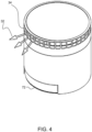
- Figures 1 to 4 show an example of a first type of air delivery system 10 to which the invention has been applied.
- the system comprises a free standing upright air purifier.
- the system has an air entry port 20 at a lower portion of the system and an air exit port 30 at the top.
- the air entry is represented by arrows 22 and the air exit is represented by arrows 32.
- the system has a housing 12.
- the ambient air is drawn into the housing through the air entry port which extends at least partly around a base part of the housing, and it passes through a filter or set of filters 14.
- a fan 16 provides an upward air flow of the filtered air.
- the fan is for example a centrifugal fan, although any suitable fan may be used.
- the flow direction from the fan may be defined by the combination of a fan impeller and a shroud around the fan impeller.
- the air entry port for example comprises a mesh all around a lower part of the outer housing 36 of the system 10.
- the air exit port 30 in this example comprises a ring of openings 34 around a top of the unit.
- the air exit port 30 has an air exit area, which is the sum of the areas of the openings 34.
- a heater 35 is provided upstream of the air exit port 30.
- a blocking arrangement 40 is provided for selectively blocking a portion of the air exit port, namely a subset of the ring of openings 36.
- the blocking arrangement comprises a shutter which is movable to a position directly behind said portion of the air exit area. Thus, it prevents the air flow from the fan exiting a portion of the ring of openings but allows air flow to exit from the remainder of the ring of openings.
- the air delivery system is in this way configurable between:
- Figure 1 also shows a water delivery system for enabling a humidifier function.
- the water delivery system comprises a water tank 17, a pump 18 and a wick 19 for delivering water to the air flow through the system.
- FIG 2 shows the system with the top removed so that the blocking arrangement 40 can be seen more easily.
- the blocking arrangement 40 comprises an annular wall which functions as a shield.
- the wall extends around an angle of 180 to 270 degrees, and 270 degrees in the example shown.
- a space is defined between the ends 42 of the wall (the space extends for 90 degrees in this example), and this space becomes the only region where an air exit flow is allowed when the blocking arrangement is engaged.
- the blocking arrangement In order to engage the blocking arrangement, it is driven up and down. When driven up, it internally covers those openings which are aligned with the wall. Thus, it acts as shutter which blocks the final flow to the openings so that all flow is redirected to the uncovered openings. When dropped down, there is no blocking function and the exit flow is uniformly from all the openings in the ring.
- Figure 2 shows a drive cog 50 and a gear 52 around the inside of a portion of the blocking arrangement.
- the blocking arrangement can thus be rotated by a small angle. This rotation is used to raise or lower the blocking arrangement, using a pin and slot arrangement.
- Figure 2 also shows the fan 16 having a fan motor 16a and a fan impeller 16b. The fan is a centrifugal or mixed flow fan.
- Figure 3 shows the blocking arrangement 40 in its dropped position, with no blocking function.
- the bottom part of Figure 3 shows the blocking arrangement 40 in its raised position so that a sub-set of the openings is blocked.
- Figure 3 shows the pin 60 and slot 62 used to convert rotation into up-down translation.
- the blocking arrangement is thereby drivable towards and away from the ring of openings, in this particular example in an up-down direction.
- Figure 4 shows the exit flow 32 when the blocking arrangement is engaged.
- the exit flow is only from a portion of the air exit port, i.e. from only a sub-set of the ring of openings.
- the flow will have a higher velocity and hence greater reach.
- the exit flow is also more directional.
- the angular direction of the space may be adjustable.
- the flow velocity can be controlled as well as the direction of the high velocity flow.
- This may involve manual rotation of a top part of the unit, or it may involve rotating the whole unit about a base 72, or it may simply involve setting the direction which the whole unit faces (i.e. choosing the position and orientation on the floor).
- the rotational control of the direction of the exit flow may instead be electrically adjustable, by having the angular position of the blocking arrangement controlled as well as the up-down position.
- the air delivery system can thus be switched between a fan mode with a high flow velocity from a small exit port (with more limited direction) and an air purification mode with a low flow velocity from a large exit port.
- the high flow velocity can for example allow a user to use the air delivery system as a cooling fan, whereas the low flow velocity can allow the user to use the air delivery system for air purification and/or for heating.
- the air delivery system will further comprise the heater 35 within the housing for heating the ambient air.
- Figure 5 is used to explain a further feature, by which the outlet of the air delivery system, which is at the top of the device, is directed upwardly. This assists in separating clean air exiting the device from dirty air entering the device, and this can thereby increase the purification efficiency.
- the exit flow 32 is shown with an upward component, and the inlet flow 38 is also shown.
- the upward component of the exit flow separates the delivered clean air from the air inlet, so that most of the air that goes through the inlet is dirty air.
- the fan delivers the exit flow in a radial direction.
- an arrangement is needed to change the direction of flow to include an axial upward direction.
- a stator downstream of the fan impeller is one option, to change the air direction, but this will increase the air path length and hence increase the air resistance. This will reduce the airflow and purification performance as well as increasing the size of device.
- the ring of openings 34 is provided radially outside the fan impeller 16b, hence in the radial direction from the impeller. This reduces the air resistance.
- the openings 34 are defined by vanes 39, and they are angled such that the exit flow is guided to a radial and upward direction, but without significantly increasing the resistance. This increases the distance between the clean air and the dirty air.
- FIG. 6 shows that the vanes 39 are at at an angle ⁇ to the radial direction. This direction of flow may also be generated by a shroud around the fan impeller, so that the shroud and the vanes have the same angle of elevation (or for example within 10 degrees of each other).
- the angled vanes can reduce the air resistance and guide the clean air exiting the device to the oblique upward direction.
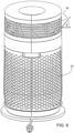
- Figures 7 to 12 show an example of a second type of air delivery system 10 to which the invention has been applied.
- the system again comprises a free standing upright air purifier.
- Figure 7 shows the system from in front and Figure 8 shows the system from behind.
- This type of fan (or heater) is known as bladeless fan. It uses multiplication of air flows to provide a high exit flow rate from a small internal fan.
- the system 10 comprises an air entry port 20 at a lower portion, and an air multiplier channel 80 extending laterally through an upper portion.
- the air exit port in this type of device comprises comprises a slot at least partially around the air multiplier channel 80.
- the air exit port comprises a first and second vertical slots 30a, 30b at the sides of the air multiplier channel 80.
- the air exit port includes a second portion 30c extending at least partially around the housing below the air multiplier channel 80.
- the second portion 30c comprises a ring or partial ring of openings 34 as described above.
- the ring in the example shown only extends partially around the housing. In particular, it extends around a back part of the housing, wherein the slots 30a, 30b are at a front part of the housing.
- the fan mode delivers air forwardly
- the air purification mode delivers air in a backward direction.
- the air inlet 20 is in this example also only at the back.
- the air exit port thus has an upper first portion arranged at the air channel 80 (for inducing a flow of ambient air through the air channel, hence creating an air multiplication), and a lower second portion arranged at the level of the fan.
- the air resistance from the fan to the second portion is less than the air resistance to the first portion, so that when all parts of the air exit port are open, the flow preferentially flows to the second portion 30c.
- the area of the second portion 30c (i.e. the combined area of the openings 34) is larger than the area of the first portion 30a, 30b, i.e. the combined area of the slots.
- the blocking arrangement of the invention is for selectively blocking the second portion 30c, i.e. all of the opening in the partial ring.
- the slots 30a, 30b have a small area to create a directed flow, in particular to create the air multiplication effect.
- the exit port may either be only the first portion, i.e. the slots 30a, 30b, for creating a high flow velocity air flow rate using the air multiplier channel, or it may be both portions.
- the air multiplier delivers a large flow rate, much of this is entrained ambient air rather than newly filtered air. Thus, the air purification volume remains low.
- the second portion 30c receives most of the flow because the area is larger and it is nearer to the internal fan.
- the ring of openings is around the fan impeller 32b. This gives a large flow rate of purified air.
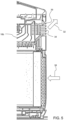
- FIG. 9 shows the system in cross section.
- the fan 16 is approximately at the same level (i.e. height up the housing) as the second portion 30c of the air exit port, i.e. the partial ring of openings.
- the fan motor 32a and impeller 32b are in the middle of device, and the filter 14 is downstream of the air inlet port inlet 20 and upstream of the fan, to purify the air.
- Figure 10 shows the fan motor 16a and impeller 16b and shows that the second portion 30c of the air exit port is around the periphery of the fan, in particular around the impeller 16b.
- the blocking arrangement 40 is similar to the example above, in that it comprises a shutter which can be raised or lowered to block the exit passage of air from the partial ring of openings.
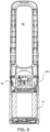
- Figure 11 shows the blocking arrangement 40, by illustrating the system with a cover removed.
- the blocking arrangement 40 comprises a wall which can be driven up and down.
- Figure 11 shows the up position of the wall, in which it blocks the second portion 30c of the exit port.
- This is the fan mode, since all air is routed to the first portion of the air exit port, i.e. the slots 30a, 30b.
- a pin 60 and slot 62 arrangement is again used to covert a small amount of rotation of the blocking arrangement 40 into up-down movement.
- the blocking arrangement is placed near the impeller of the fan. When the blocking arrangement 40 is engaged, all of the air will be blown out from the first portion of the exit port, namely the slots 30a, 30b. Because the opening area of the first portion is small, the flow velocity will be high.
- the air multiplier uses the high velocity air from the upper first portion of the air exit port to entrain the surrounding air, thereby to increase the air flow rate and enhance the cooling effect, in known manner.
- the air flow when in the air purification mode, when most of the air flows from the second portion 30c, the air flow generates a negative pressure area above the second portion 30c of the exit port, and this draws air down from the opening 80.
- the second portion When the second portion is at the back of the housing as shown, this draws air to the back of the opening 80.
- the shape of the second opening may also take advantage of the Coanda effect in steering a flow down the back of the housing. This is also assisted by the upward direction of the exit flow from the second portion using the angled vanes (and angled impeller shroud) as explained above. This reduces further the exit air flow from the first portion, which is for example not desired during air purification in the winter, when a high flow of cold air during air purification is not desired by the user.
- the heater can be placed at the top, upstream of the first portion 30a, 30b of the air exit port (to deliver high velocity hot air in the fan mode) or upstream of the second portion (to deliver low velocity high flow rate hot air in the purification mode).
- the flow from the first portion 30a, 30b is in a forward direction, and the second portion 30c of the air exit port faces in a rearward direction.
- the second portion 30c of the air exit port may instead extend all around the housing to provide the low velocity flow in all directions.
Landscapes
- Engineering & Computer Science (AREA)
- Mechanical Engineering (AREA)
- General Engineering & Computer Science (AREA)
- Chemical & Material Sciences (AREA)
- Combustion & Propulsion (AREA)
- Physics & Mathematics (AREA)
- Signal Processing (AREA)
- Fuzzy Systems (AREA)
- Mathematical Physics (AREA)
- Fluid Mechanics (AREA)
- Thermal Sciences (AREA)
- Structures Of Non-Positive Displacement Pumps (AREA)
Priority Applications (5)
| Application Number | Priority Date | Filing Date | Title |
|---|---|---|---|
| PCT/EP2022/076125 WO2023052203A1 (en) | 2021-09-30 | 2022-09-20 | An air delivery system |
| AU2022354521A AU2022354521A1 (en) | 2021-09-30 | 2022-09-20 | An air delivery system |
| EP22786928.6A EP4409202A1 (en) | 2021-09-30 | 2022-09-20 | An air delivery system |
| CN202211203947.3A CN115898914A (zh) | 2021-09-30 | 2022-09-29 | 空气输送系统 |
| CN202222596283.3U CN218882551U (zh) | 2021-09-30 | 2022-09-29 | 空气输送系统 |
Applications Claiming Priority (1)
| Application Number | Priority Date | Filing Date | Title |
|---|---|---|---|
| CN2021122392 | 2021-09-30 |
Publications (1)
| Publication Number | Publication Date |
|---|---|
| EP4160100A1 true EP4160100A1 (en) | 2023-04-05 |
Family
ID=81307803
Family Applications (2)
| Application Number | Title | Priority Date | Filing Date |
|---|---|---|---|
| EP22168183.6A Withdrawn EP4160100A1 (en) | 2021-09-30 | 2022-04-13 | An air delivery system |
| EP22786954.2A Active EP4409203B1 (en) | 2021-09-30 | 2022-09-27 | Air delivery device |
Family Applications After (1)
| Application Number | Title | Priority Date | Filing Date |
|---|---|---|---|
| EP22786954.2A Active EP4409203B1 (en) | 2021-09-30 | 2022-09-27 | Air delivery device |
Country Status (5)
| Country | Link |
|---|---|
| EP (2) | EP4160100A1 (pl) |
| CN (1) | CN217876311U (pl) |
| AU (1) | AU2022354085A1 (pl) |
| PL (1) | PL4409203T3 (pl) |
| WO (1) | WO2023052361A1 (pl) |
Citations (4)
| Publication number | Priority date | Publication date | Assignee | Title |
|---|---|---|---|---|
| EP3040632A1 (en) * | 2014-12-30 | 2016-07-06 | Samsung Electronics Co., Ltd. | Air cleaner and home appliance having air processing unit |
| US20190170162A1 (en) * | 2017-12-01 | 2019-06-06 | Dyson Technology Limited | Fan assembly |
| US20200400152A1 (en) * | 2018-03-05 | 2020-12-24 | Dyson Technology Limited | Fan assembly |
| US20210270282A1 (en) * | 2018-06-27 | 2021-09-02 | Dyson Technology Limited | Nozzle for a fan assembly |
Family Cites Families (5)
| Publication number | Priority date | Publication date | Assignee | Title |
|---|---|---|---|---|
| KR101783177B1 (ko) * | 2012-06-07 | 2017-09-28 | 미디어 그룹 코 엘티디 | 사류 팬, 사류 송풍기 및 이를 구비한 콘솔형 에어컨 |
| KR102513480B1 (ko) * | 2015-07-17 | 2023-03-27 | 삼성전자주식회사 | 공기조화기 |
| KR20200058826A (ko) * | 2018-11-20 | 2020-05-28 | 엘지전자 주식회사 | 공기청정기 |
| GB201900025D0 (en) * | 2019-01-02 | 2019-02-13 | Dyson Technology Ltd | A fan assembly |
| KR102887228B1 (ko) * | 2020-07-10 | 2025-11-14 | 엘지전자 주식회사 | 서큘레이터 및 서큘레이터를 포함하는 공기청정기 |
-
2022
- 2022-04-13 EP EP22168183.6A patent/EP4160100A1/en not_active Withdrawn
- 2022-04-14 CN CN202220880933.4U patent/CN217876311U/zh active Active
- 2022-09-27 EP EP22786954.2A patent/EP4409203B1/en active Active
- 2022-09-27 PL PL22786954.2T patent/PL4409203T3/pl unknown
- 2022-09-27 WO PCT/EP2022/076846 patent/WO2023052361A1/en not_active Ceased
- 2022-09-27 AU AU2022354085A patent/AU2022354085A1/en active Pending
Patent Citations (4)
| Publication number | Priority date | Publication date | Assignee | Title |
|---|---|---|---|---|
| EP3040632A1 (en) * | 2014-12-30 | 2016-07-06 | Samsung Electronics Co., Ltd. | Air cleaner and home appliance having air processing unit |
| US20190170162A1 (en) * | 2017-12-01 | 2019-06-06 | Dyson Technology Limited | Fan assembly |
| US20200400152A1 (en) * | 2018-03-05 | 2020-12-24 | Dyson Technology Limited | Fan assembly |
| US20210270282A1 (en) * | 2018-06-27 | 2021-09-02 | Dyson Technology Limited | Nozzle for a fan assembly |
Also Published As
| Publication number | Publication date |
|---|---|
| PL4409203T3 (pl) | 2026-03-09 |
| WO2023052361A1 (en) | 2023-04-06 |
| EP4409203A1 (en) | 2024-08-07 |
| AU2022354085A1 (en) | 2024-05-16 |
| CN217876311U (zh) | 2022-11-22 |
| EP4409203B1 (en) | 2025-12-03 |
Similar Documents
| Publication | Publication Date | Title |
|---|---|---|
| KR20160012796A (ko) | 가습청정기 | |
| AU2022354521A1 (en) | An air delivery system | |
| EP3273063B1 (en) | Blower | |
| CN208579428U (zh) | 空气净化器 | |
| GB2500274A (en) | Bladeless fan with channel to increase volume and speed of flow | |
| KR102625904B1 (ko) | 청정기 | |
| CN109780631A (zh) | 一种空调室内机、控制方法和空调器 | |
| EP3273062B1 (en) | Blower | |
| CN111868451A (zh) | 空调设备的室内机 | |
| KR101939405B1 (ko) | 열 교환기용 팬 유닛 | |
| EP4160100A1 (en) | An air delivery system | |
| US2899803A (en) | Air conditioning apparatus | |
| CN112032837A (zh) | 空调器及其出风控制方法 | |
| EP3425207B1 (en) | Blowing device | |
| KR20170040162A (ko) | 가습청정기 | |
| KR102267526B1 (ko) | 가습청정기 | |
| CN107477729A (zh) | 一种侧墙壁挂式新风机 | |
| CN220377189U (zh) | 吹风机 | |
| US20240376899A1 (en) | Fan | |
| CN216693659U (zh) | 一种加速吸烟装置及其吸油烟机 | |
| EP0723112A1 (en) | Steam generator | |
| KR102301589B1 (ko) | 청정기 | |
| EP4095391A1 (en) | Improved fan | |
| US20240149199A1 (en) | Air purification device with optimized air guidance | |
| CN215675487U (zh) | 空气调节设备 |
Legal Events
| Date | Code | Title | Description |
|---|---|---|---|
| PUAI | Public reference made under article 153(3) epc to a published international application that has entered the european phase |
Free format text: ORIGINAL CODE: 0009012 |
|
| STAA | Information on the status of an ep patent application or granted ep patent |
Free format text: STATUS: THE APPLICATION HAS BEEN PUBLISHED |
|
| AK | Designated contracting states |
Kind code of ref document: A1 Designated state(s): AL AT BE BG CH CY CZ DE DK EE ES FI FR GB GR HR HU IE IS IT LI LT LU LV MC MK MT NL NO PL PT RO RS SE SI SK SM TR |
|
| RAP3 | Party data changed (applicant data changed or rights of an application transferred) |
Owner name: VERSUNI HOLDING B.V. |
|
| STAA | Information on the status of an ep patent application or granted ep patent |
Free format text: STATUS: THE APPLICATION IS DEEMED TO BE WITHDRAWN |
|
| 18D | Application deemed to be withdrawn |
Effective date: 20231006 |