EP4160122A1 - Procédé de commande de condensation sur un appareil de réfrigération et réfrigérateur associé - Google Patents
Procédé de commande de condensation sur un appareil de réfrigération et réfrigérateur associé Download PDFInfo
- Publication number
- EP4160122A1 EP4160122A1 EP22186804.5A EP22186804A EP4160122A1 EP 4160122 A1 EP4160122 A1 EP 4160122A1 EP 22186804 A EP22186804 A EP 22186804A EP 4160122 A1 EP4160122 A1 EP 4160122A1
- Authority
- EP
- European Patent Office
- Prior art keywords
- compressor
- refrigerator
- duty cycle
- temperature
- storage compartment
- Prior art date
- Legal status (The legal status is an assumption and is not a legal conclusion. Google has not performed a legal analysis and makes no representation as to the accuracy of the status listed.)
- Withdrawn
Links
- 238000000034 method Methods 0.000 title claims abstract description 34
- 238000009833 condensation Methods 0.000 title claims abstract description 32
- 230000005494 condensation Effects 0.000 title claims abstract description 27
- 239000003507 refrigerant Substances 0.000 claims abstract description 52
- 238000009413 insulation Methods 0.000 claims abstract description 19
- 230000000977 initiatory effect Effects 0.000 claims abstract description 11
- 239000012080 ambient air Substances 0.000 claims description 16
- 238000012545 processing Methods 0.000 abstract description 7
- 238000011056 performance test Methods 0.000 abstract description 4
- 238000001816 cooling Methods 0.000 description 6
- 239000003570 air Substances 0.000 description 5
- 230000002829 reductive effect Effects 0.000 description 5
- 230000008901 benefit Effects 0.000 description 4
- 230000008569 process Effects 0.000 description 4
- 230000000694 effects Effects 0.000 description 3
- 230000009467 reduction Effects 0.000 description 3
- 238000013459 approach Methods 0.000 description 2
- 230000008859 change Effects 0.000 description 2
- 230000008878 coupling Effects 0.000 description 2
- 238000010168 coupling process Methods 0.000 description 2
- 238000005859 coupling reaction Methods 0.000 description 2
- 239000007788 liquid Substances 0.000 description 2
- 239000000463 material Substances 0.000 description 2
- 230000000717 retained effect Effects 0.000 description 2
- 238000012546 transfer Methods 0.000 description 2
- 238000010792 warming Methods 0.000 description 2
- 238000009825 accumulation Methods 0.000 description 1
- 238000004364 calculation method Methods 0.000 description 1
- 230000003247 decreasing effect Effects 0.000 description 1
- 238000011161 development Methods 0.000 description 1
- 238000010586 diagram Methods 0.000 description 1
- 239000012774 insulation material Substances 0.000 description 1
- 230000000670 limiting effect Effects 0.000 description 1
- 238000005259 measurement Methods 0.000 description 1
- 238000013508 migration Methods 0.000 description 1
- 230000005012 migration Effects 0.000 description 1
- 230000000116 mitigating effect Effects 0.000 description 1
- 238000012544 monitoring process Methods 0.000 description 1
- 230000003287 optical effect Effects 0.000 description 1
- 238000005057 refrigeration Methods 0.000 description 1
- 230000002441 reversible effect Effects 0.000 description 1
- 230000000630 rising effect Effects 0.000 description 1
- 238000007789 sealing Methods 0.000 description 1
- 230000032258 transport Effects 0.000 description 1
- 230000001960 triggered effect Effects 0.000 description 1
- 238000011144 upstream manufacturing Methods 0.000 description 1
Images


Classifications
-
- F—MECHANICAL ENGINEERING; LIGHTING; HEATING; WEAPONS; BLASTING
- F25—REFRIGERATION OR COOLING; COMBINED HEATING AND REFRIGERATION SYSTEMS; HEAT PUMP SYSTEMS; MANUFACTURE OR STORAGE OF ICE; LIQUEFACTION SOLIDIFICATION OF GASES
- F25D—REFRIGERATORS; COLD ROOMS; ICE-BOXES; COOLING OR FREEZING APPARATUS NOT OTHERWISE PROVIDED FOR
- F25D21/00—Defrosting; Preventing frosting; Removing condensed or defrost water
- F25D21/04—Preventing the formation of frost or condensate
-
- F—MECHANICAL ENGINEERING; LIGHTING; HEATING; WEAPONS; BLASTING
- F25—REFRIGERATION OR COOLING; COMBINED HEATING AND REFRIGERATION SYSTEMS; HEAT PUMP SYSTEMS; MANUFACTURE OR STORAGE OF ICE; LIQUEFACTION SOLIDIFICATION OF GASES
- F25B—REFRIGERATION MACHINES, PLANTS OR SYSTEMS; COMBINED HEATING AND REFRIGERATION SYSTEMS; HEAT PUMP SYSTEMS
- F25B49/00—Arrangement or mounting of control or safety devices
- F25B49/02—Arrangement or mounting of control or safety devices for compression type machines, plants or systems
-
- F—MECHANICAL ENGINEERING; LIGHTING; HEATING; WEAPONS; BLASTING
- F25—REFRIGERATION OR COOLING; COMBINED HEATING AND REFRIGERATION SYSTEMS; HEAT PUMP SYSTEMS; MANUFACTURE OR STORAGE OF ICE; LIQUEFACTION SOLIDIFICATION OF GASES
- F25B—REFRIGERATION MACHINES, PLANTS OR SYSTEMS; COMBINED HEATING AND REFRIGERATION SYSTEMS; HEAT PUMP SYSTEMS
- F25B13/00—Compression machines, plants or systems, with reversible cycle
-
- F—MECHANICAL ENGINEERING; LIGHTING; HEATING; WEAPONS; BLASTING
- F25—REFRIGERATION OR COOLING; COMBINED HEATING AND REFRIGERATION SYSTEMS; HEAT PUMP SYSTEMS; MANUFACTURE OR STORAGE OF ICE; LIQUEFACTION SOLIDIFICATION OF GASES
- F25B—REFRIGERATION MACHINES, PLANTS OR SYSTEMS; COMBINED HEATING AND REFRIGERATION SYSTEMS; HEAT PUMP SYSTEMS
- F25B2600/00—Control issues
- F25B2600/11—Fan speed control
-
- F—MECHANICAL ENGINEERING; LIGHTING; HEATING; WEAPONS; BLASTING
- F25—REFRIGERATION OR COOLING; COMBINED HEATING AND REFRIGERATION SYSTEMS; HEAT PUMP SYSTEMS; MANUFACTURE OR STORAGE OF ICE; LIQUEFACTION SOLIDIFICATION OF GASES
- F25B—REFRIGERATION MACHINES, PLANTS OR SYSTEMS; COMBINED HEATING AND REFRIGERATION SYSTEMS; HEAT PUMP SYSTEMS
- F25B2700/00—Sensing or detecting of parameters; Sensors therefor
- F25B2700/02—Humidity
-
- F—MECHANICAL ENGINEERING; LIGHTING; HEATING; WEAPONS; BLASTING
- F25—REFRIGERATION OR COOLING; COMBINED HEATING AND REFRIGERATION SYSTEMS; HEAT PUMP SYSTEMS; MANUFACTURE OR STORAGE OF ICE; LIQUEFACTION SOLIDIFICATION OF GASES
- F25B—REFRIGERATION MACHINES, PLANTS OR SYSTEMS; COMBINED HEATING AND REFRIGERATION SYSTEMS; HEAT PUMP SYSTEMS
- F25B2700/00—Sensing or detecting of parameters; Sensors therefor
- F25B2700/21—Temperatures
- F25B2700/2104—Temperatures of an indoor room or compartment
-
- F—MECHANICAL ENGINEERING; LIGHTING; HEATING; WEAPONS; BLASTING
- F25—REFRIGERATION OR COOLING; COMBINED HEATING AND REFRIGERATION SYSTEMS; HEAT PUMP SYSTEMS; MANUFACTURE OR STORAGE OF ICE; LIQUEFACTION SOLIDIFICATION OF GASES
- F25B—REFRIGERATION MACHINES, PLANTS OR SYSTEMS; COMBINED HEATING AND REFRIGERATION SYSTEMS; HEAT PUMP SYSTEMS
- F25B2700/00—Sensing or detecting of parameters; Sensors therefor
- F25B2700/21—Temperatures
- F25B2700/2106—Temperatures of fresh outdoor air
-
- F—MECHANICAL ENGINEERING; LIGHTING; HEATING; WEAPONS; BLASTING
- F25—REFRIGERATION OR COOLING; COMBINED HEATING AND REFRIGERATION SYSTEMS; HEAT PUMP SYSTEMS; MANUFACTURE OR STORAGE OF ICE; LIQUEFACTION SOLIDIFICATION OF GASES
- F25D—REFRIGERATORS; COLD ROOMS; ICE-BOXES; COOLING OR FREEZING APPARATUS NOT OTHERWISE PROVIDED FOR
- F25D29/00—Arrangement or mounting of control or safety devices
Definitions
- the present device generally relates to a refrigerator, and more specifically, to a refrigerator having anti-condensation features.
- a method of controlling condensation on an appliance includes the steps of (1) providing a refrigerator with a cabinet structure, a door operably coupled to the cabinet structure for selectively providing access to a storage compartment, a compressor, one or more sensors, a controller operably coupled to the compressor and the one or more sensors, a heat loop operably coupled to the compressor, wherein the heat loop circulates a heated medium during a duty cycle of the compressor; (2) sensing a first temperature level using the one or more sensors within the storage compartment at a first time interval during an off-duty cycle of the compressor; (3) sensing a second temperature level using the one or more sensors within the storage compartment at a second time interval during the off-duty cycle of the compressor; (4) calculating a rate of temperature rise within the storage compartment using the controller; (5) initiating the duty cycle of the compressor when the rate of temperature rise reaches a predetermined threshold rate; and (6) changing an operating parameter of the refrigerator to increase the duty cycle of the compressor.
- a method of controlling condensation on an appliance includes the steps of (1) providing a refrigerator having a refrigerant circuit with a heat loop, wherein the heat loop is configured to circulate heated refrigerant adjacent to an exterior surface of a cabinet structure during a duty cycle of a compressor; (2) using one or more sensors to collect data, wherein the data includes a temperature value of the exterior surface of the cabinet structure, an ambient air temperature value associated with the exterior surface of the cabinet structure, and a relative humidity value associated with the exterior surface of the cabinet structure; (3) sending the data to a controller for processing; (4) calculating a dew point temperature value from the data using the controller; (5) comparing the dew point temperature value with the temperature value of the exterior surface of the cabinet structure using the controller; (6) initiating the duty cycle of the compressor when the temperature value of the exterior surface of the cabinet structure reaches a threshold temperature relative to the dew point temperature value; and (7) changing an operating parameter of the refrigerator to increase a time interval for which the duty cycle of the compressor is run.
- a method of controlling condensation on an appliance includes the steps of (1) providing a refrigerator having a refrigerant circuit with a heat loop, wherein the heat loop is configured to circulate heated refrigerant within a cabinet structure during a duty cycle of a compressor, and further wherein the refrigerator includes a storage compartment and an insulation space substantially surrounding the same; (2) running an insulation performance test, wherein a rate of temperature rise within the storage compartment is calculated during an off-duty cycle of the compressor; (3) sending the data to a controller for processing; (4) initiating the duty cycle of the compressor when the rate of temperature rise reaches a predetermined threshold rate; and (5) changing an operating parameter of the refrigerator to increase a time interval for which the duty cycle of the compressor is run.
- the present illustrated embodiments reside primarily in combinations of method steps and apparatus components related to an anti-condensation feature for an appliance. Accordingly, the apparatus components and method steps have been represented, where appropriate, by conventional symbols in the drawings, showing only those specific details that are pertinent to understanding the embodiments of the present disclosure so as not to obscure the disclosure with details that will be readily apparent to those of ordinary skill in the art having the benefit of the description herein. Further, like numerals in the description and drawings represent like elements.
- the terms “upper,” “lower,” “right,” “left,” “rear,” “front,” “vertical,” “horizontal,” and derivatives thereof shall relate to the disclosure as oriented in FIG. 1 .
- the term “front” shall refer to the surface of the element closer to an intended viewer, and the term “rear” shall refer to the surface of the element further from the intended viewer.
- the disclosure may assume various alternative orientations, except where expressly specified to the contrary.
- the specific devices and processes illustrated in the attached drawings, and described in the following specification are simply exemplary embodiments of the inventive concepts defined in the appended claims. Hence, specific dimensions and other physical characteristics relating to the embodiments disclosed herein are not to be considered as limiting, unless the claims expressly state otherwise.
- substantially is intended to note that a described feature is equal or approximately equal to a value or description.
- a “substantially planar” surface is intended to denote a surface that is planar or approximately planar.
- substantially is intended to denote that two values are equal or approximately equal.
- substantially may denote values within about 10% of each other, such as within about 5% of each other, or within about 2% of each other.
- a refrigerator 1 includes a cabinet structure 2 which, in the embodiment of FIG. 1 , further includes a refrigerator compartment 28 positioned above a freezer compartment 44.
- the refrigerator compartment 28 and the freezer compartment 44 may be referred to herein as compartments 28, 44 and may also be referred to herein on an individual basis as a storage compartment.
- Doors 5 and 6 are provided to selectively provide access to the refrigerator compartment 28, while a drawer 7 is used to provide access to the freezer compartment 44.
- the cabinet structure 2 is surrounded by an exterior wrapper 8.
- the configuration of the refrigerator 1 as shown in FIG. 1 is exemplary only and the present concept is contemplated for use in all refrigerator styles including, but not limited to, side-by-side refrigerators, whole refrigerator and freezers, and refrigerators with upper freezer compartments.
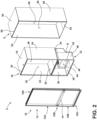
- the cabinet structure 2 generally includes a trim breaker 10.
- the trim breaker 10 or thermal bridge, includes a frame 12 having an upper opening 12A and a lower opening 12B with a mullion portion 14 disposed therebetween.
- the trim breaker 10 further includes an upper portion 10A, a middle portion 10B and a lower portion 10C.
- the cabinet structure 2 further includes a refrigerator liner 16 having a top wall 18, a bottom wall 20, opposed sidewalls 22, 24, and a rear wall 26. Together, the walls 18, 20, 22, and 24 of the refrigerator liner 16 cooperate to define the refrigerator compartment 28 when the cabinet structure 2 is assembled.
- the refrigerator liner 16 further includes a front edge 30 disposed on a front portion thereof. The front edge 30 is disposed along the top wall 18, the bottom wall 20 and the opposed sidewalls 22, 24 in a quadrilateral ring configuration.
- a freezer liner 32 is provided and includes a top wall 34, a bottom wall 36, opposed sidewalls 38, 40, and a rear wall 42. Together, the walls 34, 36, 38, 40 and 42 of the freezer liner 32 cooperate to define the freezer compartment 44.
- the rear wall 42 is shown in FIG. 2 as being a contoured rear wall that provides a spacing S for housing mechanical equipment 43 ( FIG. 4 ) for cooling both the refrigerator compartment 28 and freezer compartment 44.
- Such equipment may include a compressor, a condenser, an expansion valve, an evaporator, a plurality of conduits, and other related components used for cooling the refrigerator and freezer compartments 28, 44, as further described below with specific reference to FIG. 7 .
- the freezer liner 32 includes a front edge 46 disposed on a front portion thereof.
- the front edge 46 is disposed along the top wall 34, the bottom wall 36 and the opposed sidewalls 38, 40 in a quadrilateral ring configuration.
- the front edge 30 of the refrigerator liner 16 and the front edge 46 of the freezer liner 32 are configured to couple with coupling portions disposed about the upper and lower openings 12A, 12B of the trim breaker 10.
- the cabinet structure 2 also includes the exterior wrapper 8.
- the exterior wrapper 8 includes a top wall 50, a bottom wall 52, opposed sidewalls 54, 56, and a rear wall 58 which cooperate to define a cavity 59.
- the exterior wrapper 8 further includes a front edge 60 which is disposed along the top wall 50, the bottom wall 52, and the opposed sidewalls 54, 56 in a quadrilateral ring configuration.
- the front edge 60 of the exterior wrapper 8 is coupled to coupling portions of the trim breaker 10 around the refrigerator liner 16 and the freezer liner 32. In this way, the trim breaker 10 interconnects the exterior wrapper 8 and the refrigerator liner 16 and the freezer liner 32 when assembled.
- the refrigerator liner 16 and the freezer liner 32 are received within the cavity 59 of the exterior wrapper 8 when assembled, such that an insulation space 62 ( FIG. 3 ) is defined between the outer surfaces of the refrigerator liner 16 and the freezer liner 32 relative to the inner surfaces of the exterior wrapper 8.
- the insulation space 62 can be used to create a vacuum insulated cavity provided at a negative pressure, or can be used to receive an insulation material to insulate the refrigerator compartment 28 and the freezer compartment 44, or both.
- the trim breaker 10 may be configured to provide an air-tight connection between the exterior wrapper 8 and the liners 16, 32 which allows for a vacuum to be held between the trim breaker 10, the exterior wrapper 8 and the liners 16, 32 in the insulation space 62 ( FIG. 3 ).
- the trim breaker 10 may also be formed from any suitable material that is substantially impervious to gasses to maintain a vacuum in the insulation space 62, if so desired.
- the trim breaker 10 connects to the front edge 60 ( FIG. 2 ) of the exterior wrapper 8, and further connects to the front edge 30 ( FIG. 2 ) of the refrigerator liner 16, and to the front edge 46 ( FIG. 2 ) of the freezer liner 32. In this way, the trim breaker 10 interconnects the exterior wrapper 8 and the liners 16, 32.
- the exterior wrapper 8 is typically exposed to ambient room temperature air, whereas the liners 16, 32 are generally exposed to refrigerated air in the refrigerator compartment 28 or the freezer compartment 44.
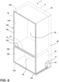
- the trim breaker 10 With the trim breaker 10 being made of a material that is substantially non-conductive with respect to heat, the trim breaker 10 reduces transfer of heat from the exterior wrapper 8 to the liners 16, 32. As shown in FIG.3 , the insulation space 62 substantially surrounds the refrigerator compartment 28 and the freezer compartment 44.
- the refrigerator 1 is shown in a cross-sectional view having the refrigerator liner 16 and the freezer liner 32 coupled to the trim breaker 10 at upper and lower openings 12A, 12B, respectively.
- the exterior wrapper 8 is also coupled to the trim breaker 10, such that the trim breaker 10 interconnects the exterior wrapper 8 with the refrigerator liner 16 and freezer liner 32.
- the trim breaker 10 of the present concept is coupled to the liners 16, 32 and exterior wrapper 8 to hermetically seal the components together as a unitary whole as shown in FIG. 3 .
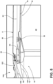
- the trim breaker 10 is shown along the upper portion 10A thereof.
- the trim breaker 10 includes a door-to-cabinet interface 72 that defines a sealing surface for the refrigerator 1 between the trim breaker 10 and the doors 5, 6 and drawer 7 ( FIG. 1 ) thereof.
- An outwardly opening channel 68 is disposed along the door-to-cabinet interface 72 of the trim breaker 10, and a heat loop 100 is shown positioned therein.
- the heat loop 100 comprises a continuous conduit of tubing 102 that is routed through the refrigerator 1 ( FIG. 1 ), and is substantially disposed along the door-to-cabinet interface 72, as best shown in FIG. 6 .
- the heat loop 100 is configured to circulate heated refrigerant adjacent to an exterior surface of a cabinet structure 2 during a duty cycle of a compressor.
- the heat loop 100 may be referred to herein as a conduit, a Yoder loop or a condenser loop, but is not meant to be limited to any one shape or configuration by the term "loop.”
- the heat loop 100 circulates, or otherwise transports, a heated medium, such as heated refrigerant that is generated by the mechanical equipment 43 ( FIGS. 4 and 6 ) when the mechanical equipment 43 is cooling the compartments 28 and 44.
- the heated refrigerant contained and transported through the tubing 102 of the heat loop 100 provides for an anti-condensation feature to help prevent condensation that can develop when the cold surfaces of the compartments 28 and 44 are exposed to ambient air in which the refrigerator 1 is disposed. This warm and humid air can cause condensation to develop along the door-to-cabinet interface 72 of the trim breaker 10.
- the circulating warmed refrigerant of the heat loop 100 provides a mitigating factor for combatting condensation buildup, particularly at the door-to-cabinet interface 72 where condensation is likely to occur.
- the heat loop 100 positioned in the outwardly opening channel 68 (see FIG. 5 ) of the trim breaker 10 is substantially disposed around the door-to-cabinet interface 72.
- the term "substantially disposed" indicates that the majority of the conduit defining the heat loop 100 is disposed along the door-to-cabinet interface 72 of the refrigerator 1, where the refrigerator 1 is most susceptible to condensation accumulation.
- An intermediate portion 104 of the tubing 102 of the heat loop 100 is shown covering the mullion portion 14 of the trim breaker 10.
- the heat loop 100 fully surrounds the openings 12A and 12B of the trim breaker 10 along the door-to-cabinet interface 72.
- a return portion 107 is illustrated as running the heat loop 100 back to the spacing S of the refrigerator 1 where the mechanical equipment 43 is housed that generates the heated refrigerant for circulation within the heat loop 100.
- the refrigerator 1 is shown with a refrigerant circuit 120 and various control components. More particularly, the refrigerant circuit 120 includes conduits (not labeled) allowing for a flow of refrigerant 128 through a compressor 122, to a condenser 124, to the heat loop 100, to a pressure reduction device 126, to an evaporator 132 and then back to the compressor 122.
- the compressor 122 supplies refrigerant 128 through a compressor outlet line 130 to the condenser 124.
- a check valve 134 may be placed in the compressor outlet line 130 to prevent reverse migration of refrigerant back into the compressor 122 during compressor OFF cycles.
- the condenser 124 is optionally paired with a variable-speed condenser fan 135.
- the condenser fan 135 can operate to improve an efficiency of the condenser 124 by imparting a flow of ambient air over the condenser 124. This additional air flow over the condenser 124 facilitates additional heat transfer (i.e., heat removal) during the phase change of refrigerant 128 from a gas to a liquid within condenser 124. As such, the refrigerant 128 is heated within the condenser 124 and directed to the heat loop 100.
- the heat loop 100 is contemplated to be positioned at the door-to-cabinet interface 72 along the refrigerator 1, as best shown in FIG. 6 .
- the refrigerant 128 then flows out of the heat loop 100 and is presented to the pressure reduction device 126, which is located upstream from the evaporator 132. Accordingly, the refrigerant 128 flows through the pressure reduction device 126 and into the evaporator 132. The refrigerant 128 then exits the evaporator 132 and flows through a compressor inlet line 136 back into the compressor 122, thus completing refrigerant circuit 120.
- the compressor 122 may be a single-speed or single-capacity compressor that is appropriately sized based on the particular system parameters of the refrigerator 1.
- the compressor 122 may also be a multi-capacity compressor capable of operation at any one of a finite group of capacities or speeds.
- the compressor 122 may also be a variable capacity or variable speed compressor (e.g., a variable speed, reciprocating compressor operating from 1600 to 4500 rpm or 3:1 capacity range) or a linear compressor, capable of operating within a large, continuous range of compressor speeds and capacities.
- the refrigerator 1 will likely include variable-speed compartment fans and/or evaporator fans, such as fans 144, 146, 142 shown in FIG. 7 .
- a controller 140 is provided.
- the controller 140 is contemplated to control the general operations of the refrigerator 1.
- the controller 140 operates the compressor 122, for example, to maintain the refrigerator compartment 28 and the freezer compartment 44 at various temperatures desired by the user.
- the controller 140 may operate the condenser fan 135 (if present) to further effect control of the temperature in the refrigerator compartment 28 and the freezer compartment 44.
- the controller 140 may operate an evaporator fan 142, a freezer compartment fan 144, a refrigerator compartment fan 146 and/or the check valve 134 to maintain desired temperatures in the refrigerator compartment 28 and the freezer compartment 44.
- controller 140 may be configured to control and optimize the thermodynamic efficiency of the refrigerator 1 by controlling or adjusting speeds of the compressor 122, the condenser fan 135, the evaporator fan 142, the freezer compartment fan 144 and/or the refrigerator compartment fan 146.
- the controller 140 is configured to receive and generate control signals via interconnecting wires provided in the form of leads arranged between and coupled to the compressor 122, the condenser fan 135, the evaporator fan 142, the freezer compartment fan 144, and the refrigerator compartment fan 146.
- a lead 122a is arranged to couple the controller 140 with the compressor 122.
- Lead 134a is arranged to couple the controller 140 with the check valve 134.
- Lead 135a is arranged to couple the controller 140 with the condenser fan 135.
- leads 142a, 144a, and 146a are arranged to couple the controller 140 with the evaporator fan 142, the freezer compartment fan 144, and the refrigerator compartment fan 146, respectively.
- the controller 140 also relies on compartment temperature sensors to perform its intended function within the refrigerator 1.
- controller 140 is operably coupled to sensors 23 and 25 via leads 23a and 25a, respectively.
- the sensors 23 and 25 are arranged in the refrigerator compartment 28 and the freezer compartment 44, respectively.
- the sensors 23 and 25 are configured to generate signals indicative of temperature levels in their respective compartments 28 and 44, and send this data to the controller 140.
- Thermistors, thermocouples, and other types of temperature sensors known in the art are suitable for use as the sensors 23 and 25.
- a sensor 21 is shown in FIG.
- the sensor 21 is also configured to provide temperature information for a particular surface of the refrigerator 1 one which the sensor 21 is disposed. Information provided from the sensor 21 is delivered to the controller 140 via lead 21a. It is further contemplated that the sensors 21, 23 and 25 may be wirelessly coupled to the controller 140 for collecting and delivering signal information thereto.
- the present concept provides for the controller 140 to adjust cooling component parameters to initiate circulation of heated refrigerant 128 through the heat loop 100 as an anti-condensation measure of the refrigerator 1.
- the sensor 21 is contemplated to be an exterior sensor positioned on an exterior surface of the refrigerator 1.
- An exterior surface of the refrigerator 1 is used herein to denote a portion of the exterior wrapper 8 or the trim breaker 10, or a cover covering the trim breaker 10 that is exposed to the outside environment or ambient air in which the refrigerator 1 is disposed.
- the sensor 21 may include multiple sensors that can provide the different values necessary for running a runtime algorithm for the refrigerant circuit 120.
- the controller 140 is configured to receive data from the sensor 21 via lead 21a which operably couples the sensor 21 to the controller 140.
- the data received from sensor 21 is used in controlling the refrigerant circuit 120, such as runtime, duration, modulated power level, and other like parameters of the mechanical equipment 43 used to cool the compartments 28, 44 of the refrigerator 1.
- the controller 140 of the present concept is configured to provide a more effective anti-condensation feature for the refrigerator 1.
- the controller 140 may be hardwired to the sensors 21, 23 and 25, or may be electronically coupled with the sensors 21, 23 and 25 using a wireless connection.
- the sensors 21, 23 and 25 may be described as monitoring, sensing, detecting and providing data regarding the refrigerator compartments 28, 44, the ambient air around the refrigerator 1, the relative humidity, or the exterior surfaces of the refrigerator 1. All such terms, and other like terms, are contemplated to indicate that the sensors 21, 23 and 25 are configured to gather data and send the same to the controller 140 for processing.
- the sensors 21, 23 and 25 may, either alone or in combination, include temperature sensors configured to provide temperature values for the ambient air temperature from the environment in which the refrigerator 1 is located, the refrigerator compartment temperature, and the freezer compartment temperature, respectively.
- Such temperature sensing units may include thermistors or other like sensors.
- Such relative humidity sensing units may also include optical sensors configured to detect the presence of condensation.
- the sensors 21, 23 and 25 may, either alone or in combination, include dew point sensing units configured to provide dew point temperature values for the environment in which the refrigerator 1 is disposed.
- dew point sensing units may be configured to send dew point calculations to the controller 140 for further processing and for controlling the refrigerant circuit 120 (and associated heat loop 100).
- the mechanical equipment 43 of the refrigerator 1 can be adjusted to effectively combat the development of dew/condensation on surfaces of the refrigerator in a more energy efficient manner, and in real time.
- the dew point temperature (Td) will be compared with a temperature value of the exterior surface of the refrigerator 1 itself (Txr).
- the temperature value (Txr) of the refrigerator 1 may be a temperature of a particular surface of the refrigerator 1 taken by sensor 21 in an area where condensation is likely to form, such as the door-to-cabinet interface 72 of the refrigerator 1.
- the refrigerant circuit 120 can be adjusted by the controller 140.
- Txr temperature of the exterior surface of the cabinet structure 2
- Td dew point temperature
- the controller 140 will initiate a refrigerant circulation sequence as the temperature (Txr) of the exterior surface of the refrigerator 1 approaches the dew point temperature (Td) to keep moisture from developing on exterior surface of the refrigerator 1.
- a refrigerant circulation sequence can be triggered as the temperature (Txr) of the exterior surface of the refrigerator 1 approaches a temperature level that is less than 1°C away from the dew point temperature (Td).
- the present concept provides for another way in which a refrigerant circulation sequence can be initiated to circulate heated refrigerant 128 through the heat loop 100.
- the refrigerator 1 is provided with a vacuum insulated cabinet structure 2 and vacuum insulated doors 5, 6, the thermal conductivity can lessen over time, such that insulating performance may need to be evaluated.
- the refrigerator 1 may be designed to allow a pressure level increase from 1 to 10 mbar over the life of the product.
- the door-cabinet interface 72 is often the first place where condensation will be observed if the insulation performance begins to lessen.
- the dew point is calculated by the controller 140 using the sensor 21. This requires the sensor 21 to be capable of measuring the ambient air temperature level and the relative humidity level. With the current temperature and humidity conditions, the dew point can be calculated by the controller 140. After the dew point is calculated, potential condensation conditions can be detected in a second step. This can be done by running an insulation performance test to estimate the current insulation performance by observing the rate of temperature rise in either the refrigerator compartment 28 or the freezer compartment 44 during an off-cycle of the compressor 122 and, as a corollary, the refrigerant circuit 120.
- the compressor 122 When the compressor 122 is running, the refrigerant 128 in the heat loop 100 warms the cabinet structure 2 along the areas where the heat loop 100 is routed, such as the door-to-cabinet interface 72. When the compressor 122 is off, no refrigerant 128 is pumped through the heat loop 100 and these areas will then cool.
- the rate of temperature rise in either the refrigerator compartment 28 or the freezer compartment 44 during an off-cycle of the refrigerant circuit 120 can be combined with the ambient air temperature level taken from the first step to estimate how effective the insulation is and if the performance of the insulation has degraded over time.
- Off-cycle readings can be affected by many outside factures, such as a user opening the refrigerator doors 5, 6, or if a user puts something warm inside the refrigerator compartment 28 or the freezer compartment 44 to be cooled. Such occurrences will cause for the off-cycle time to be shorter than normal.
- the controller 140 can be programmed to evaluate off-cycles in which no door opening event occurred. Said differently, the doors (5, 6) of the refrigerator 1 are continuously closed and retained in the closed position during the off-duty cycle in which the first temperature level and the second temperature level are sensed by the sensors (23 or 25). Several measurements could be taken during such an off-cycle to thereby provide a series of temperature levels sensed, from which an average can be calculated.
- the calculated average rate of temperature rise can be evaluated by the controller 140 in order to reduce variation due to other factors and provide a consistent number for the average rate of temperature rise. If the average rate of temperature rise evaluated meets a predetermined threshold, the controller 140 can initiate a duty cycle of the compressor 122. Condensation will form on surfaces that have a surface temperature below the dew point of the ambient air. Thus, if insulation performance is less than optimal, increased rates of temperature rise will be detected in the refrigerator compartment 28 or the freezer compartment 44. This will lead to cooler temperatures for the exterior surfaces of the refrigerator 1, and therefore, these exterior surface temperatures may fall below the dew point of the ambient air in which the refrigerator 1 is located.
- Determining the rate of temperature rise can be done using sensor 23 or sensor 25, or both. In this way, either the refrigerator compartment temperature level or the freezer compartment temperature level can be evaluated for a rising temperature rate over time.
- This method generally includes sensing a first temperature level using the one or more sensors (23 or 25) within the storage compartment (28 or 44) at a first time interval during an off-duty cycle of the compressor 122; sensing a second temperature level using the one or more sensors (23 or 25) within the storage compartment (28 or 44) at a second time interval during the off-duty cycle of the compressor 122; calculating a rate of temperature rise within the storage compartment (28 or 44) using the controller 140; initiating the duty cycle of the compressor 122 when the rate of temperature rise reaches a predetermined threshold rate; and changing an operating parameter of the refrigerator 1 to increase the duty cycle of the compressor 122.
- a threshold rate of temperature rise may include a fixed value that is programmed to initiate the circulation of refrigerant by initiating the duty cycle of the compressor 122 in order to avoid condensation.
- the threshold rate of temperature rise and the threshold temperature noted above can be stored values retained by and preprogrammed into the controller 140. Further, the threshold rate of temperature rise and the threshold temperature noted above are exemplary values only, and are not mean to limit the scope of the present concept.
- a control algorithm of the controller 140 can be adjusted by changing an operating parameter of the refrigerator 1 to increase the duty cycle (runtime) of the compressor 122 in order to circulate warm refrigerant 128 through the heat loop 100 for longer time intervals.
- An increased time interval for the circulation of warm refrigerant 128 helps to reduce or eliminate external condensation at the door-to-cabinet interface 72 by warming the exterior surfaces of the refrigerator 1.
- a first operating parameter adjustment involves an adjustment of a speed of the compressor 122 as run during a duty cycle.
- the compressor 122 is a variable speed compressor, or a linear compressor which can be run at variable speeds
- the speed at which the compressor 122 is run can be reduced to a lower or lowest speed setting during a duty cycle of the compressor 122 in order to increase the overall run time of the compressor 122 during a duty cycle.
- the evaporator fan 142 is variable speed fan or a pulse width modulation (PWM) controlled device, the speed of the evaporator fan 142 can be reduced to increase the run time of the compressor 122 as another operating parameter adjustment.
- PWM pulse width modulation
- the evaporator fan 142 is not a variable speed fan, then the evaporator fan 142 could be turned off or deactivated during the cooling cycle to get a similar effect. With the evaporator fan 142 reduced in speed or turned off, the duty cycle of the compressor 122 will increase from a standard duty cycle, as the storage compartment (28 or 44) will take longer to cool. Similarly, if the condenser fan 135 is variable speed or PWM controlled device, the speed of the condenser fan 135 could be reduced as another operating parameter adjustment. If the condenser fan 135 is not a variable speed or PWM controlled device, then the condenser fan 135 could be turned off or deactivated during the cooling cycle to get a similar effect.
- the duty cycle of the compressor 122 will increase as compared to a standard duty cycle, as the condenser 124 will take longer to condense the refrigerant 128 into a liquid medium.
- Reducing air flow over the condenser 124 by manipulating the behavior of the condenser fan 135 has the additional benefit of raising the condensing temperature.
- the condensing temperature increases, so does the temperature of the refrigerant 128 cycled through the heat loop 100 which has the additional benefit of warming the door-to-cabinet interface 72 in an effort to combat or avoid external condensation.
- a method of controlling condensation on an appliance includes the steps of (1) providing a refrigerator with a cabinet structure, a door operably coupled to the cabinet structure for selectively providing access to a storage compartment, a compressor, one or more sensors, a controller operably coupled to the compressor and the one or more sensors, a heat loop operably coupled to the compressor, wherein the heat loop circulates a heated medium during a duty cycle of the compressor; (2) sensing a first temperature level using the one or more sensors within the storage compartment at a first time interval during an off-duty cycle of the compressor; (3) sensing a second temperature level using the one or more sensors within the storage compartment at a second time interval during the off-duty cycle of the compressor; (4) calculating a rate of temperature rise within the storage compartment using the controller; (5) initiating the duty cycle of the compressor when the rate of temperature rise reaches a predetermined threshold rate; and (6) changing an operating parameter of the refrigerator to increase the duty cycle of the compressor.
- the heat loop is substantially disposed along a door-to-cabinet interface of the cabinet structure.
- the heated medium is a refrigerant.
- the door of the refrigerator is continuously closed during the off-duty cycle in which the first temperature level and the second temperature level are sensed.
- the first and second temperature levels are first and second temperature levels of a series of temperature levels sensed during the off-duty cycle of the compressor.
- an average rate of temperature rise within the storage compartment is calculated using data from the series of temperature levels sensed during the off-duty cycle of the compressor, and the duty cycle of the compressor is initiated when the average rate of temperature rise within the storage compartment reaches the predetermined threshold rate.
- the step of changing an operating parameter of the refrigerator to increase the duty cycle of the compressor includes reducing a speed of the compressor.
- the refrigerator includes an evaporator fan
- the step of changing an operating parameter of the refrigerator to increase the duty cycle of the compressor includes reducing a speed of the evaporator fan
- the step of reducing a speed of the evaporator fan further includes deactivating the evaporator fan.
- the refrigerator includes a condenser fan
- the step of changing an operating parameter of the refrigerator to increase the duty cycle of the compressor includes reducing a speed of the condenser fan
- the step of reducing a speed of the condenser fan further includes deactivating the condenser fan.
- a method of controlling condensation on an appliance includes the steps of (1) providing a refrigerator having a refrigerant circuit with a heat loop, wherein the heat loop is configured to circulate heated refrigerant adjacent to an exterior surface of a cabinet structure during a duty cycle of a compressor; (2) using one or more sensors to collect data, wherein the data includes a temperature value of the exterior surface of the cabinet structure, an ambient air temperature value associated with the exterior surface of the cabinet structure, and a relative humidity value associated with the exterior surface of the cabinet structure; (3) sending the data to a controller for processing; (4) calculating a dew point temperature value from the data using the controller; (5) comparing the dew point temperature value with the temperature value of the exterior surface of the cabinet structure using the controller; (6) initiating the duty cycle of the compressor when the temperature value of the exterior surface of the cabinet structure reaches a threshold temperature relative to the dew point temperature value; and (7) changing an operating parameter of the refrigerator to increase a time interval for which the duty cycle of the compressor is run.
- the step of changing an operating parameter of the refrigerator to increase a time interval for which the duty cycle of the compressor is run includes reducing a speed of the compressor.
- the refrigerator includes an evaporator fan
- the step of changing an operating parameter of the refrigerator to increase a time interval for which the duty cycle of the compressor is run includes reducing a speed of the evaporator fan
- the step of reducing a speed of the evaporator fan further includes deactivating the evaporator fan.
- the refrigerator includes a condenser fan
- the step of changing an operating parameter of the refrigerator to increase a time interval for which the duty cycle of the compressor is run includes reducing a speed of the condenser fan
- the step of reducing a speed of the condenser fan further includes deactivating the condenser fan.
- a method of controlling condensation on an appliance includes the steps of (1) providing a refrigerator having a refrigerant circuit with a heat loop, wherein the heat loop is configured to circulate heated refrigerant within a cabinet structure during a duty cycle of a compressor, and further wherein the refrigerator includes a storage compartment and an insulation space substantially surrounding the same; (2) running an insulation performance test, wherein a rate of temperature rise within the storage compartment is calculated during an off-duty cycle of the compressor; (3) sending the data to a controller for processing; (4) initiating the duty cycle of the compressor when the rate of temperature rise reaches a predetermined threshold rate; and (5) changing an operating parameter of the refrigerator to increase a time interval for which the duty cycle of the compressor is run.
- a series of temperature levels are sensed within the storage compartment during the off-duty cycle of the compressor
- the refrigerator includes a door to the storage compartment that remains closed during the off-duty cycle of the compressor in which the series of temperature levels are sensed, and an average rate of temperature rise within the storage compartment is calculated using data from the series of temperature levels sensed during the off-duty cycle of the compressor, and the duty cycle of the compressor is initiated when the average rate of temperature rise within the storage compartment reaches the predetermined threshold rate.
- the step of changing an operating parameter of the refrigerator to increase a time interval for which the duty cycle of the compressor is run includes at least one of the following operating parameters: reducing a speed of the compressor; reducing a speed of an evaporator fan; and reducing a speed of a condenser fan.
- a method of controlling condensation on an appliance includes the steps of (1) providing a refrigerator with a cabinet structure, a door operably coupled to the cabinet structure for selectively providing access to a storage compartment, a compressor, one or more sensors, a controller operably coupled to the compressor and the one or more sensors, a heat loop operably coupled to the compressor, wherein the heat loop circulates a heated medium during a duty cycle of the compressor; (2) sensing a first temperature level using the one or more sensors within the storage compartment at a first time interval during an off-duty cycle of the compressor; (3) sensing a second temperature level using the one or more sensors within the storage compartment at a second time interval during the off-duty cycle of the compressor; (4) calculating a rate of temperature rise within the storage compartment using the controller; (5) initiating the duty cycle of the compressor when the rate of temperature rise reaches a predetermined threshold rate; and (6) changing an operating parameter of the refrigerator to increase the duty cycle of the compressor.
- the door of the refrigerator is continuously closed during the off-duty cycle in which the first temperature level and the second temperature level are sensed.
- the first and second temperature levels are first and second temperature levels of a series of temperature levels sensed during the off-duty cycle of the compressor.
- an average rate of temperature rise within the storage compartment is calculated using data from the series of temperature levels sensed during the off-duty cycle of the compressor.
- the duty cycle of the compressor is initiated when the average rate of temperature rise within the storage compartment reaches the predetermined threshold rate.
- the step of changing an operating parameter of the refrigerator to increase the duty cycle of the compressor includes reducing a speed of the compressor.
- the refrigerator includes an evaporator fan.
- the step of changing an operating parameter of the refrigerator to increase the duty cycle of the compressor includes reducing a speed of the evaporator fan.
- the step of reducing a speed of the evaporator fan further includes deactivating the evaporator fan.
- the refrigerator includes a condenser fan.
- the step of changing an operating parameter of the refrigerator to increase the duty cycle of the compressor includes reducing a speed of the condenser fan.
- the step of reducing a speed of the condenser fan further includes deactivating the condenser fan.
- the heat loop is substantially disposed along a door-to-cabinet interface of the cabinet structure.
- the heated medium is a refrigerant.
Landscapes
- Engineering & Computer Science (AREA)
- Physics & Mathematics (AREA)
- Mechanical Engineering (AREA)
- Thermal Sciences (AREA)
- General Engineering & Computer Science (AREA)
- Chemical & Material Sciences (AREA)
- Combustion & Propulsion (AREA)
- Devices That Are Associated With Refrigeration Equipment (AREA)
Applications Claiming Priority (1)
| Application Number | Priority Date | Filing Date | Title |
|---|---|---|---|
| US17/492,717 US12331973B2 (en) | 2021-10-04 | 2021-10-04 | Refrigerator with anti-condensation features |
Publications (1)
| Publication Number | Publication Date |
|---|---|
| EP4160122A1 true EP4160122A1 (fr) | 2023-04-05 |
Family
ID=82742929
Family Applications (1)
| Application Number | Title | Priority Date | Filing Date |
|---|---|---|---|
| EP22186804.5A Withdrawn EP4160122A1 (fr) | 2021-10-04 | 2022-07-25 | Procédé de commande de condensation sur un appareil de réfrigération et réfrigérateur associé |
Country Status (3)
| Country | Link |
|---|---|
| US (1) | US12331973B2 (fr) |
| EP (1) | EP4160122A1 (fr) |
| CN (1) | CN115930516A (fr) |
Families Citing this family (1)
| Publication number | Priority date | Publication date | Assignee | Title |
|---|---|---|---|---|
| US20260055946A1 (en) * | 2024-08-21 | 2026-02-26 | Haier Us Appliance Solutions, Inc. | Refrigerator appliance self-optimizing control scheme |
Citations (4)
| Publication number | Priority date | Publication date | Assignee | Title |
|---|---|---|---|---|
| JPH10197122A (ja) * | 1997-01-08 | 1998-07-31 | Toshiba Corp | スプリット型冷蔵庫 |
| EP2172725A1 (fr) * | 2008-10-03 | 2010-04-07 | Whirpool Corporation | Réfrigérateur doté d'un contrôle optimisé de la conservation des aliments |
| US20120017612A1 (en) * | 2010-07-20 | 2012-01-26 | Brent Alden Junge | System to control external condensation on a refrigerator |
| EP2743616A2 (fr) * | 2012-12-11 | 2014-06-18 | Dongbu Daewoo Electronics Corporation | Réfrigérateur comportant une prévention de rosée et/ou dispositif de commande et procédé pour empêcher la formation de rosée dans celui-ci et/ou sur celui-ci |
Family Cites Families (12)
| Publication number | Priority date | Publication date | Assignee | Title |
|---|---|---|---|---|
| US4481787A (en) * | 1982-07-16 | 1984-11-13 | Whirlpool Corporation | Sequentially controlled single evaporator refrigerator |
| JP2000065461A (ja) | 1998-08-20 | 2000-03-03 | Hitachi Ltd | 冷蔵庫及びかかる冷蔵庫における結露防止運転制御方法 |
| JP2003302146A (ja) | 2002-04-05 | 2003-10-24 | Toshiba Corp | 冷蔵庫 |
| US7165411B2 (en) * | 2004-09-03 | 2007-01-23 | Nissan Technical Center North America, Inc. | Control logic for HVAC heat management |
| KR20120023272A (ko) * | 2010-09-01 | 2012-03-13 | 삼성전자주식회사 | 직냉식 냉장고 및 그 제어방법 |
| JP2014020715A (ja) | 2012-07-20 | 2014-02-03 | Toshiba Corp | 冷蔵庫 |
| US10634414B2 (en) * | 2016-01-04 | 2020-04-28 | Haier Us Appliance Solutions, Inc. | Method for operating a fan within a refrigerator appliance |
| US20170211871A1 (en) * | 2016-01-21 | 2017-07-27 | General Electric Company | Sealed System and a Method For Defrosting an Evaporator |
| CN106766578B (zh) | 2016-12-23 | 2019-07-02 | 青岛海尔股份有限公司 | 冷藏冷冻设备的防凝露方法与装置 |
| CN106802051A (zh) | 2017-02-06 | 2017-06-06 | 青岛海尔股份有限公司 | 冷藏冷冻装置及其防凝露控制方法 |
| CN106839608B (zh) | 2017-03-03 | 2019-12-10 | 青岛海尔股份有限公司 | 具有防凝露功能的冰箱与冰箱的防凝露控制方法 |
| JP6838535B2 (ja) * | 2017-09-21 | 2021-03-03 | 株式会社デンソー | 冷凍サイクル装置 |
-
2021
- 2021-10-04 US US17/492,717 patent/US12331973B2/en active Active
-
2022
- 2022-07-25 EP EP22186804.5A patent/EP4160122A1/fr not_active Withdrawn
- 2022-09-27 CN CN202211181295.8A patent/CN115930516A/zh active Pending
Patent Citations (4)
| Publication number | Priority date | Publication date | Assignee | Title |
|---|---|---|---|---|
| JPH10197122A (ja) * | 1997-01-08 | 1998-07-31 | Toshiba Corp | スプリット型冷蔵庫 |
| EP2172725A1 (fr) * | 2008-10-03 | 2010-04-07 | Whirpool Corporation | Réfrigérateur doté d'un contrôle optimisé de la conservation des aliments |
| US20120017612A1 (en) * | 2010-07-20 | 2012-01-26 | Brent Alden Junge | System to control external condensation on a refrigerator |
| EP2743616A2 (fr) * | 2012-12-11 | 2014-06-18 | Dongbu Daewoo Electronics Corporation | Réfrigérateur comportant une prévention de rosée et/ou dispositif de commande et procédé pour empêcher la formation de rosée dans celui-ci et/ou sur celui-ci |
Also Published As
| Publication number | Publication date |
|---|---|
| CN115930516A (zh) | 2023-04-07 |
| US20230105421A1 (en) | 2023-04-06 |
| US12331973B2 (en) | 2025-06-17 |
Similar Documents
| Publication | Publication Date | Title |
|---|---|---|
| KR101130638B1 (ko) | 냉각 저장고 및 그 압축기의 제어 방법 | |
| EP3356752B1 (fr) | Contrôle de température des cavités de réfrigération dans des conditions de basse température ambiante | |
| US12173950B2 (en) | Temperature control of refrigeration cavities with a variable speed compressor and a variable speed evaporator fan | |
| EP0803689B1 (fr) | Régulation de la température d'un appareil avec determination de la température ambiante | |
| JP6366237B2 (ja) | 冷蔵庫 | |
| AU2015410544A1 (en) | Refrigerator | |
| JP2001082850A (ja) | 冷蔵庫 | |
| EP4160122A1 (fr) | Procédé de commande de condensation sur un appareil de réfrigération et réfrigérateur associé | |
| CN112639382B (zh) | 冰箱及其控制方法 | |
| JP2007071520A (ja) | 冷却貯蔵庫及びその圧縮機の制御方法 | |
| US12298069B2 (en) | Vacuum insulated appliance with pressure monitoring | |
| US10429863B2 (en) | Systems and methods for refrigerator control | |
| US20160084565A1 (en) | Refrigerator appliance and method of operating a refrigerator appliance | |
| JP5927428B2 (ja) | 冷蔵庫 | |
| JP7201450B2 (ja) | 恒温高湿庫 | |
| CA2414048C (fr) | Methode et appareil de commande de temperature de systeme de refroidissement | |
| KR100597304B1 (ko) | 냉장고의 제상 운전방법 | |
| KR100291300B1 (ko) | 3면입체냉장고에서의센서제어장치및그방법 | |
| JP2014156946A (ja) | 冷蔵庫 | |
| JP3180275B2 (ja) | 冷蔵庫 | |
| KR20200041198A (ko) | 냉장고 및 그 냉장고의 제어 방법 | |
| JPH09229530A (ja) | 冷蔵庫 | |
| KR20070032417A (ko) | 냉장고의 보관온도 제어장치 |
Legal Events
| Date | Code | Title | Description |
|---|---|---|---|
| PUAI | Public reference made under article 153(3) epc to a published international application that has entered the european phase |
Free format text: ORIGINAL CODE: 0009012 |
|
| STAA | Information on the status of an ep patent application or granted ep patent |
Free format text: STATUS: THE APPLICATION HAS BEEN PUBLISHED |
|
| AK | Designated contracting states |
Kind code of ref document: A1 Designated state(s): AL AT BE BG CH CY CZ DE DK EE ES FI FR GB GR HR HU IE IS IT LI LT LU LV MC MK MT NL NO PL PT RO RS SE SI SK SM TR |
|
| P01 | Opt-out of the competence of the unified patent court (upc) registered |
Effective date: 20230920 |
|
| STAA | Information on the status of an ep patent application or granted ep patent |
Free format text: STATUS: THE APPLICATION IS DEEMED TO BE WITHDRAWN |
|
| 18D | Application deemed to be withdrawn |
Effective date: 20231006 |