EP4160132B1 - Rohrwicklung einer gaskondensationswärmeaustauschzelle für einen kessel - Google Patents
Rohrwicklung einer gaskondensationswärmeaustauschzelle für einen kessel Download PDFInfo
- Publication number
- EP4160132B1 EP4160132B1 EP22178478.8A EP22178478A EP4160132B1 EP 4160132 B1 EP4160132 B1 EP 4160132B1 EP 22178478 A EP22178478 A EP 22178478A EP 4160132 B1 EP4160132 B1 EP 4160132B1
- Authority
- EP
- European Patent Office
- Prior art keywords
- tube
- sides
- value
- curvature
- tube profile
- Prior art date
- Legal status (The legal status is an assumption and is not a legal conclusion. Google has not performed a legal analysis and makes no representation as to the accuracy of the status listed.)
- Active
Links
Images


Classifications
-
- F—MECHANICAL ENGINEERING; LIGHTING; HEATING; WEAPONS; BLASTING
- F24—HEATING; RANGES; VENTILATING
- F24H—FLUID HEATERS, e.g. WATER OR AIR HEATERS, HAVING HEAT-GENERATING MEANS, e.g. HEAT PUMPS, IN GENERAL
- F24H1/00—Water heaters, e.g. boilers, continuous-flow heaters or water-storage heaters
- F24H1/22—Water heaters other than continuous-flow or water-storage heaters, e.g. water heaters for central heating
- F24H1/40—Water heaters other than continuous-flow or water-storage heaters, e.g. water heaters for central heating with water tube or tubes
- F24H1/43—Water heaters other than continuous-flow or water-storage heaters, e.g. water heaters for central heating with water tube or tubes helically or spirally coiled
-
- F—MECHANICAL ENGINEERING; LIGHTING; HEATING; WEAPONS; BLASTING
- F28—HEAT EXCHANGE IN GENERAL
- F28D—HEAT-EXCHANGE APPARATUS, NOT PROVIDED FOR IN ANOTHER SUBCLASS, IN WHICH THE HEAT-EXCHANGE MEDIA DO NOT COME INTO DIRECT CONTACT
- F28D21/00—Heat-exchange apparatus not covered by any of the groups F28D1/00 - F28D20/00
- F28D21/0001—Recuperative heat exchangers
- F28D21/0003—Recuperative heat exchangers the heat being recuperated from exhaust gases
- F28D21/0005—Recuperative heat exchangers the heat being recuperated from exhaust gases for domestic or space-heating systems
- F28D21/0007—Water heaters
-
- F—MECHANICAL ENGINEERING; LIGHTING; HEATING; WEAPONS; BLASTING
- F24—HEATING; RANGES; VENTILATING
- F24H—FLUID HEATERS, e.g. WATER OR AIR HEATERS, HAVING HEAT-GENERATING MEANS, e.g. HEAT PUMPS, IN GENERAL
- F24H1/00—Water heaters, e.g. boilers, continuous-flow heaters or water-storage heaters
- F24H1/10—Continuous-flow heaters, i.e. heaters in which heat is generated only while the water is flowing, e.g. with direct contact of the water with the heating medium
- F24H1/12—Continuous-flow heaters, i.e. heaters in which heat is generated only while the water is flowing, e.g. with direct contact of the water with the heating medium in which the water is kept separate from the heating medium
- F24H1/14—Continuous-flow heaters, i.e. heaters in which heat is generated only while the water is flowing, e.g. with direct contact of the water with the heating medium in which the water is kept separate from the heating medium by tubes, e.g. bent in serpentine form
- F24H1/16—Continuous-flow heaters, i.e. heaters in which heat is generated only while the water is flowing, e.g. with direct contact of the water with the heating medium in which the water is kept separate from the heating medium by tubes, e.g. bent in serpentine form helically or spirally coiled
- F24H1/165—Continuous-flow heaters, i.e. heaters in which heat is generated only while the water is flowing, e.g. with direct contact of the water with the heating medium in which the water is kept separate from the heating medium by tubes, e.g. bent in serpentine form helically or spirally coiled using fluid fuel
-
- F—MECHANICAL ENGINEERING; LIGHTING; HEATING; WEAPONS; BLASTING
- F24—HEATING; RANGES; VENTILATING
- F24H—FLUID HEATERS, e.g. WATER OR AIR HEATERS, HAVING HEAT-GENERATING MEANS, e.g. HEAT PUMPS, IN GENERAL
- F24H8/00—Fluid heaters characterised by means for extracting latent heat from flue gases by means of condensation
-
- F—MECHANICAL ENGINEERING; LIGHTING; HEATING; WEAPONS; BLASTING
- F28—HEAT EXCHANGE IN GENERAL
- F28D—HEAT-EXCHANGE APPARATUS, NOT PROVIDED FOR IN ANOTHER SUBCLASS, IN WHICH THE HEAT-EXCHANGE MEDIA DO NOT COME INTO DIRECT CONTACT
- F28D21/00—Heat-exchange apparatus not covered by any of the groups F28D1/00 - F28D20/00
-
- F—MECHANICAL ENGINEERING; LIGHTING; HEATING; WEAPONS; BLASTING
- F28—HEAT EXCHANGE IN GENERAL
- F28D—HEAT-EXCHANGE APPARATUS, NOT PROVIDED FOR IN ANOTHER SUBCLASS, IN WHICH THE HEAT-EXCHANGE MEDIA DO NOT COME INTO DIRECT CONTACT
- F28D7/00—Heat-exchange apparatus having stationary tubular conduit assemblies for both heat-exchange media, the media being in contact with different sides of a conduit wall
- F28D7/02—Heat-exchange apparatus having stationary tubular conduit assemblies for both heat-exchange media, the media being in contact with different sides of a conduit wall the conduits being helically coiled
- F28D7/024—Heat-exchange apparatus having stationary tubular conduit assemblies for both heat-exchange media, the media being in contact with different sides of a conduit wall the conduits being helically coiled the conduits of only one medium being helically coiled tubes, the coils having a cylindrical configuration
-
- F—MECHANICAL ENGINEERING; LIGHTING; HEATING; WEAPONS; BLASTING
- F28—HEAT EXCHANGE IN GENERAL
- F28F—DETAILS OF HEAT-EXCHANGE AND HEAT-TRANSFER APPARATUS, OF GENERAL APPLICATION
- F28F1/00—Tubular elements; Assemblies of tubular elements
- F28F1/02—Tubular elements of cross-section which is non-circular
- F28F1/04—Tubular elements of cross-section which is non-circular polygonal, e.g. rectangular
-
- F—MECHANICAL ENGINEERING; LIGHTING; HEATING; WEAPONS; BLASTING
- F28—HEAT EXCHANGE IN GENERAL
- F28D—HEAT-EXCHANGE APPARATUS, NOT PROVIDED FOR IN ANOTHER SUBCLASS, IN WHICH THE HEAT-EXCHANGE MEDIA DO NOT COME INTO DIRECT CONTACT
- F28D21/00—Heat-exchange apparatus not covered by any of the groups F28D1/00 - F28D20/00
- F28D2021/0019—Other heat exchangers for particular applications; Heat exchange systems not otherwise provided for
- F28D2021/0024—Other heat exchangers for particular applications; Heat exchange systems not otherwise provided for for combustion apparatus, e.g. for boilers
-
- F—MECHANICAL ENGINEERING; LIGHTING; HEATING; WEAPONS; BLASTING
- F28—HEAT EXCHANGE IN GENERAL
- F28F—DETAILS OF HEAT-EXCHANGE AND HEAT-TRANSFER APPARATUS, OF GENERAL APPLICATION
- F28F2250/00—Arrangements for modifying the flow of the heat exchange media, e.g. flow guiding means; Particular flow patterns
- F28F2250/02—Streamline-shaped elements
-
- Y—GENERAL TAGGING OF NEW TECHNOLOGICAL DEVELOPMENTS; GENERAL TAGGING OF CROSS-SECTIONAL TECHNOLOGIES SPANNING OVER SEVERAL SECTIONS OF THE IPC; TECHNICAL SUBJECTS COVERED BY FORMER USPC CROSS-REFERENCE ART COLLECTIONS [XRACs] AND DIGESTS
- Y02—TECHNOLOGIES OR APPLICATIONS FOR MITIGATION OR ADAPTATION AGAINST CLIMATE CHANGE
- Y02B—CLIMATE CHANGE MITIGATION TECHNOLOGIES RELATED TO BUILDINGS, e.g. HOUSING, HOUSE APPLIANCES OR RELATED END-USER APPLICATIONS
- Y02B30/00—Energy efficient heating, ventilation or air conditioning [HVAC]
Definitions
- the present invention belongs to the technical field of heat exchangers and relates to a tube profile for manufacturing a heat exchanger, where the tube profile is adapted to cause a first fluid to flow therein and to be externally lapped by a second fluid, allowing a heat exchange between the first fluid and the second fluid through the tube profile.
- the first fluid is a liquid, generally water, for a heating or domestic water system
- the second fluid consists of the hot combustion fumes of a gas-air mixture.
- the invention further relates to a tube winding comprising the aforesaid tube profile, suitably shaped for a gas heat exchange cell for a boiler for environmental heating and/or for heating domestic water, e.g., for a heat exchange cell for a condensing boiler.
- a condensing gas boiler for heating generally is a device in which a heat transfer fluid to be heated, generally water, flows by traveling through a heat exchanger, which is in contact with a flow of hot fumes transmitting heat to the heat transfer fluid.
- the hot fumes are generated in a combustion chamber comprising a burner capable of producing heat from the combustion of a mixture of combustion air and gas.
- a heat exchanger for a boiler also referred to as a heat exchange cell, comprises a tube bundle in which the heat transfer fluid circulates, in particular water to be heated
- Such a tube bundle sometimes comprises tubes connected in series and/or parallel to one another, for example, substantially straight, or it comprises a tube winding, where the tube is wound as a solenoid or a helix according to a plurality of turns about a central axis forming an inner central chamber for said winding and wound by said winding, adapted to form a combustion chamber in use.
- Such a tube winding is generally referred to as a "spiral" winding as the tube is wound according to a series of turns about a central axis.
- the exchanger comprises a tube winding
- the latter is contained inside a container body extending about, and outside, said tube winding thus forming an outer chamber, which is radially interposed with respect to the central axis, between the tube winding and the casing, adapted to form a fume collection chamber in use.
- the heat transfer fluid in particular water to be heated, flows inside the tube forming the tube winding, while a gas-air combustion is performed in the inner central combustion chamber, in which the flames of the burner is generated.
- the resulting combustion fumes externally lap the tube forming the tube winding by flowing, according to a radial direction orthogonal to the central axis of the tube winding, from the combustion chamber to the fume collection chamber, passing through a calibrated passage, formed by an axial space, between each turn and the adjacent turns.
- Such a type of heat exchange cell is referred to as a condensing heat exchange cell and is used in a condensing boiler.
- the wound tube of the tube winding has a cross section being circular in shape or rectangular with radial edges or oval or rectangular having a portion exposed to the source of heat in the shape of a semi-circle.
- the prior art also provides that there is a calibrated passage between one turn and the adjacent one, or between one tube and the adjacent one.
- Tube cross-section shapes are known, which are symmetrical to a smaller axis of such a cross-section, having a portion facing the combustion chamber, or fume inlet portion, which is substantially equal to a fume outlet portion opposite to the fume inlet portion, seen according to a flow direction of such fumes.
- the high heat exchange coefficient generated for the movement of the fumes in the passage between the turns allows reaching high levels of efficiency, but the level of pollutants generated and emitted is barely sufficient to respect current legal requirements and is elevated and beyond the limits with respect to the expectations of the future standards.
- a tube profile for manufacturing a heat exchanger for a boiler e.g., a condensing boiler, capable of reducing the production of combustion pollutants, as well as improving the thermal efficiency.
- US 2017/102164 A1 discloses a tube profile according to the preamble of claim 1.
- a tube winding in particular for a gas heat exchange cell, e.g., of the condensing type, for a boiler for heating an environment and/or domestic water, which allows meeting the aforesaid needs and overcoming, at least partially, the drawbacks claimed above with reference to the prior art.
- a tube profile as well as by a tube exchanger having said tube profile, and by a tube winding for a heat exchange cell for a boiler for heating an environment and/or domestic water, as well as by a condensing heat exchange cell having such a tube winding, in accordance with the independent claims.
- a tube profile e.g., for manufacturing a heat exchanger for a boiler, for example for a condensing boiler, has the cross-section thereof comprising a rectangular portion having two greater sides parallel to each other and two smaller sides parallel to each other and orthogonal to the greater sides, and an ogival portion with a base and two curved sides, where said base coincides with a first side of said two smaller sides of the rectangular portion, and where each of said two curved sides continuously joins to one end of a respective one of said two greater sides in a first joining point, each of said two curved sides being tangent to said respective one of said two greater sides in said first joining point, where the two greater sides, a second side of said two smaller sides, and said two curved sides define the outer surfaces of the walls of said tube profile.
- a flow of hot fumes having a predetermined direction and orientation laps the outer lateral surface of the tube according to a direction from the ogival portion to the rectangular portion.
- the geometry of the claimed cross-section meets this requirement, therefore it allows optimizing the heat exchange at a constant quantity of material which is used.
- the rectangular portion of the cross-section of the tube profile allows having a hot fume flow speed along the greater sides of the rectangular portion of such a section which is uniform and on average higher than that along the ogival portion, along which the curve of the hot fume speed varies gradually, reducing the speed peaks.
- the shape of the cross-section of the tube profile according to the invention if the pollutant level is desired to be kept more or less equal to that of a profile according to the prior art, allows reducing the air index of the combustion, resulting in further increasing the efficiency with respect to the traditional profile.
- a reduction in the air index corresponds to a better thermal efficiency but, on the other hand, to an increased production of pollutants, which has represented an obstacle to increasing the efficiency for traditional profiles.
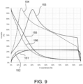
- figure 9 shows a comparison of the speed and temperature trends of the bullet-shaped cross-section according to the invention with respect to a traditional cross-section having the portion exposed to the fumes in the shape of a semi-circle, where the outer perimeter of the bullet-shaped cross-section is equal to the outer perimeter of the cross-section of the profile having the portion exposed to the fumes in the shape of a semi-circle.
- the continuous line 151 and the dashed line 152 represent an upper half of a bullet-shaped cross-section according to the invention with respect to the axis of symmetry S-S, and a corresponding upper half of a traditional cross-section having the portion exposed to the fumes in a shape of semi-circle, respectively.
- the continuous line 153 represents the trend of the fume speed along the outer surface of the bullet-shaped cross-section according to the invention
- the dashed line 154 represents the trend of the fume speed along the outer surface of a traditional cross-section having the portion exposed to the fumes in a shape of semi-circle.
- the continuous line 155 represents the trend of the fume temperature along the outer surface of the bullet-shaped cross-section according to the invention
- the dashed line 156 represents the trend of the fume temperature along the outer surface of the traditional cross-section having the portion exposed to the fumes in the shape of a semi-circle.
- the geometry of the cross-section of the bullet-shaped tube profile according to the invention has a more gradual trend of the fume speed than the traditional tube, which has instead a more marked speed peak.
- this allows the tube profile according to the invention to complete the combustion reaction and thus reduce the level of pollutants with respect to a tube cross-section having the portion exposed to the fumes in the shape of a semi-circle.
- the traditional tube profile e.g., having the portion exposed to the fumes with a semi-circular shape, having a relatively high speed peak, gives rise to the formation of pollutants, in particular carbon monoxide CO.
- the shape of the cross-section of the tube profile according to the invention gives rise to a high thermal efficiency with respect to that of a known tube profile having the portion of the cross-section exposed to the fumes in the shape of a semi-circle.
- Another advantage produced by the geometry of the cross-section of the tube profile according to the invention is the reduction of the potential effects of erosion of the outer surface of the tube profile.
- the particular shape of the cross-section of the tube profile according to the invention reduces the potential risk of erosion of the metal of the tube at local speed peaks caused by the concurrence of high speed and high temperature, which are reduced and beneficial for said profile.
- the cross-section of the tube profile according to the invention comprising a rectangular portion and an ogival portion, allows increasing the passage sections of the fumes between one tube profile and another tube profile, which are mutually adjacent along the ogival portion with respect to a tube having a circular cross-section with equal perimeter.
- the cross-section of the tube profile according to the invention allows extending the passages of the fumes between one tube profile and another tube profile, which are mutually adjacent along the greater sides of the rectangular portion, and allows reducing the size of the smaller side of the rectangular section opposite to the ogival portion, where the heat exchange is very low, resulting in the aforesaid advantages.
- a tube profile according to the invention is globally indicated by reference numeral 1.
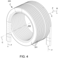
- a tube winding formed with the tube profile 1 according to the invention is globally indicated by reference numeral 200.
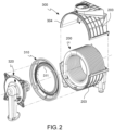
- a gas condensing heat exchange cell containing the tube winding 200 is generally indicated by reference numeral 300.
- an "axial direction” will be understood as a Z direction, coinciding with, or parallel to, the central winding axis C-C, and a radial direction R will be understood as a direction orthogonal to the central winding axis C-C.
- a "development axis" F of the tube profile is understood as a line extending along the central axis of the tube.
- a "cross-section" of the tube profile is as a section made by means of a sectional plane orthogonal to the central axis of the tube.
- a “tube profile” is understood as a tubular elongated element.
- the tube profile 1 is particularly adapted to manufacture a heat exchanger for a condensing boiler.
- the cross-section 10 of the tube profile 1 comprises a rectangular portion 20 having two greater sides 21, 22 parallel to each other and two smaller sides 31, 32 parallel to each other and orthogonal to the greater sides 21, 22, and an ogival portion 40 defined by a convex flat figure formed by a base 41 and two curved sides 42, 43 connected to each other in an apical zone 48 opposite to said base 41.
- the cross-section 10 of the tube profile 1 consists of said rectangular portion 20 and said ogival portion 40.
- the base 41 coincides with a first side 31 of said two smaller sides 31, 32 of the rectangular portion 20, therefore it has the same length as the first smaller side 31 of the two smaller sides of the rectangular portion.
- the two curved sides 42, 43 are symmetrical to an axis of symmetry S-S parallel to the greater sides 21, 22 of the rectangular portion and passing through the central points 33, 34 of said smaller sides 31, 32 of the rectangular portion.
- Each of said two curved sides 42, 43 extends continuously from, and tangent to a respective one of said two greater sides 21, 22.
- each of said two curved sides 42, 43 joins to one end of a respective one of said two greater sides 21, 22 in a first joining point PH1, each of said two curved sides 42, 43 being tangent to said respective one of said two greater sides 21, 22 in said first joining point PH1.
- the overall size of said ogival portion HO equal to the difference between the overall cross-section width H and the width H1 of the rectangular portion measured along the axis of symmetry S-S, is greater than the length of said base 41, thus greater than the length of the first smaller side 31 of the rectangular portion 20.
- the two greater sides 21, 22, a second side of said two smaller sides 32, and said two curved sides 42, 43 define the outer surfaces 50 of the walls of said tube profile 1.
- the tube profile is made of a material configured to be used in a heat exchanger, therefore such a material has a high thermal conductivity, e.g., it is made of metal, e.g., of aluminum or an alloy thereof, e.g., of steel.
- the tube profile 1 configured to be internally crossed by a fluid to be heated and to be externally lapped by a heating fluid having a higher temperature than the fluid to be heated, is arranged with the ogival portion 40 thereof facing in the flow direction of the heating fluid, but in the opposite direction to the direction of such a flow, while the rectangular portion is arranged oriented according to the direction of the flow.
- the ogival portion corresponds to a "hot side” of the tube profile, while the rectangular portion corresponds to a "cold side” of the tube profile.
- the ogival portion is configured to face a hot source, e.g., a combustion chamber, in countercurrent to the flow direction of the hot fumes from the hot source or the combustion chamber. That is, the flow of hot fumes first hits the ogival portion and then the remaining part of the cross-section.
- a hot source e.g., a combustion chamber
- the ogival portion faces the opposite direction to the advancing direction of the fumes, and since the fumes are introduced into the passages between one tube profile and another adjacent one, meeting first the ogival portion and then the rectangular one, the ogival portion can be seen as a fume inlet portion, and the rectangular portion can be seen as a fume outlet portion.
- the cross-section 10 of the tube profile 1 has a symmetrical shape with respect to an axis of symmetry S-S parallel to said greater sides 21, 22 and passing through the central points 33, 34 of said smaller sides 31, 32.
- the cross-section 10 of the tube profile 1 preferably has a non-symmetrical shape to an axis orthogonal to the axis of symmetry S-S.
- the cross-section of the fume inlet portion is different from the cross-section of the fume outlet portion.
- the cross-section 10 of the tube profile 1 consists of only one rectangular portion 20 and only one ogival portion 40, having the opposite end of the cross-section with respect to the ogival portion 40, being flat or substantially flat in shape.
- the opposite end of the cross-section with respect to the ogival portion 40, or the second side 32 of said two smaller sides 31, 32 of the rectangular portion can have a slight curvature outwards, preferably with a high value of radius of curvature, e.g., with radius of curvature being greater than the overall cross-section width value H or greater than double the value H of the overall cross-section width, for example.
- the heat exchange efficiency value between the first and second fluids through the tube profile 1 according to the invention is greater than any cross-section shape being symmetrical to an axis orthogonal to the axis of symmetry S-S.
- the cross-section 10 has an overall cross-section width value H measured along a direction parallel to said two greater sides 21, 22 and an overall cross-section height value L measured along a direction orthogonal to said two greater sides 21, 22, where the overall cross-section width value H is greater than said overall cross-section height value L.
- the overall cross-section height value L is about 1/3 of the overall cross-section width value H.
- the size of the ogival portion 40 measured in a direction parallel to the greater sides 21, 22 of the rectangular portion is about 1/3 of the overall cross-section width value H.
- the value of the width H1 of the rectangular portion measured along the axis of symmetry S-S is substantially equal to the value of the radius of curvature R3 of each of said two curved sides 42, 43 in said joining point PH1.
- the two curved sides 42, 43 of said ogival portion are connected to each other by means of an apex connection arc of circumference 44 having a first preset value of apex radius of curvature R1, for example the apex connection arc of circumference 44 is tangent to the two curved sides 42, 43 of said ogival portion 40.
- each curved side 42, 43 of said ogival portion 40 comprises at least two successive arcs of a circle 45, 46, each having a respective preset constant value of radius of curvature R2, R3, and where each arc of circumference 45, 46 is arranged so as to have said respective preset constant value of radius of curvature R2, R3 in an increasing order proceeding in a direction from said ogival portion 40 towards said rectangular portion 10, said successive arcs of circumference 45, 46 having centers of curvature C2, C3 not mutually coinciding, and where each arc of circumference of said at least two successive arcs of circumference 45, 46 is tangent to the adjacent arcs of circumference.
- the apex radius of curvature value R1 is smaller than the smallest of the values of radius of curvature of said at least two successive arcs of circumference 45, 46.
- each curved side 42, 43 of said ogival portion 40 is formed by a second arc of circumference 45 having a second preset value of radius of curvature R2 and by a third arc of circumference 46 having a third value of radius of curvature R3, where the third arc of circumference 46 is connected and tangent to one of said greater sides 21, 22, and the second arc of circumference 45 is connected and tangent to said third arc of circumference 45, and where the second value of radius of curvature R2 is less than the third value of radius of curvature R3.
- the apex radius of curvature value R1 is smaller than the second radius of curvature value R2.
- each curved side 42, 43 of said ogival portion 40 has a radius of curvature of gradually decreasing value proceeding from said base 41 towards said apical zone 48.
- each curved side 42, 43 of said ogival portion 40 has a radius of curvature of gradually decreasing value proceeding from said base 41 towards said apical zone 48 according to an elliptical function.
- the two curved sides 42, 43 of the ogival portion 40 globally form half of an ellipse, where the smaller axis of the ellipse coincides with the base of the ogival portion 41, and where the greater axis of the ellipse lies on the axis of symmetry S-S.
- the center of the ellipse is arranged in the central point 34 of the first smaller side 31 of the rectangular portion.
- each of the two greater sides 21, 22 of the rectangular portion 20 is connected to the second side 32 of said two smaller sides of said rectangular portion 20 by means of a respective end arc of circumference 47 having a preset end radius of curvature value R4.
- said end radius of R 4 ⁇ ⁇ ⁇ 1 ⁇ ⁇ H 10 curvature value R4 has the following value: where:
- said end radius of curvature value R4 is less than, or equal to, 1/2 of the overall cross-section height value L.
- the value of the aforesaid constant ⁇ is given by the relationship: 2.5 ⁇ ⁇ ⁇ 4
- a tube heat exchanger 100 comprising at least one tube profile 1 with any of the features described above, where the tube profile 1 is adapted to be internally crossed by a first fluid 101 to be heated, and is adapted to be externally lapped by a second heating fluid 102 according to a predetermined flow direction and orientation 103, where said predetermined flow direction 103 is orthogonal to an extension direction F-F of the tube profile, where said rectangular portion 20 of the cross-section 10 of said tube profile 1 is arranged with the two greater sides 21, 22 thereof along said predetermined flow direction 103, and with said ogival portion 40 facing an opposite direction to said predetermined flow direction 103.
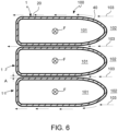
- a tube winding 200 in particular for a gas condensing heat exchange cell 300 for a boiler for heating an environment.
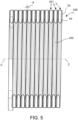
- the aforesaid tube winding 200 is formed by a tube profile 1 having any of the features described above, wound according to a plurality of turns 201 about a central winding axis C-C.
- the turns 201 of said plurality are spaced apart from one another according to a direction parallel to the central axis C-C forming calibrated axial passages (A) therebetween, adapted to be crossed, in a radial direction R with respect to said central axis C-C, from the central axis towards C-C the exterior of the tube winding.
- the tube winding 200 defines a central chamber 202 radially inside said at least one tube winding 200 and coaxial to said central axis C-C, defining a combustion chamber 202.
- the combustion chamber 202 is laterally delimited by the surfaces of said turns 201, corresponding to the ogival portion 40 of each of them.
- the rectangular portion 20 of the cross-section 10 of said tube profile 1 is arranged with the two greater sides 21, 22 thereof lying on planes orthogonal to the central axis C-C of the tube winding 200, and the ogival portion 40 of the cross-section 10 of said tube profile 1 faces said central axis C-C.
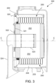
- a gas condensing heat exchange cell 300 for a boiler for heating an environment comprising at least one tube winding 200, as described above, adapted to be crossed by a heat transfer fluid.
- the heat exchange cell comprises a container body 203 containing said at least one tube winding 200 therein, where the container body 203 is arranged about, and outside, said at least one tube winding 200, forming a fume collection chamber 204 arranged radially outside said at least one tube winding 200 and radially interposed between said tube winding 200 and said container body 203 so that the fumes of the combustion which takes place in the combustion chamber 202 can flow from the combustion chamber 202 to the fume collection chamber 204 through said axial space A between said turns 201, lapping said at least one tube winding 200 and transferring an amount of heat to said heat transfer fluid.
- the second smaller sides 32 of the rectangular portions 20 of the cross-sections 10 define a radially internal lateral surface of said fume collection chamber 204.
- the heat exchange cell 300 comprises a closing flange 310, preferably made from a printed sheet, configured to close a front opening 304 of the container body 203.
- the closing flange 310 has a central flange opening 311 configured to allow access to the interior of the combustion chamber 202 for carrying out maintenance.
- the heat exchange cell 300 comprises a closing door 320 adapted to be removably mounted to said closing flange 310 for closing said central flange opening 311 in use.
- the closing door 320 supports, on an inner face 321 thereof, a gas burner 323 so that it is arranged, in use, inside the combustion chamber 202 and, on the outer face 322 thereof, a feeding sleeve 324 for feeding a combustible gas-air mixture to said burner 323.
- Figure 9 illustrates a comparison of the speed and temperature trends of the bullet-shaped cross-section according to the invention with respect to a traditional cross-section having the portion exposed to the fumes in the shape of a semi-circle, where the outer perimeter of the bullet-shaped cross-section is equal to the outer perimeter of the cross-section of the profile having the portion exposed to the fumes in the shape of a semi-circle.
- the continuous line 151 and the dashed line 152 represent an upper half of a bullet-shaped cross section according to the invention, and an upper half of a traditional cross-section having the portion exposed to the fumes shaped as a semi-circle, respectively.
- the continuous line 153 represents the trend of the fume speed along the outer surface of the bullet-shaped cross-section according to the invention
- the dashed line 154 represents the trend of the fume speed along the outer surface of a traditional tube cross-section having the portion exposed to the fumes shaped as a semi-circle.
- the continuous line 155 represents the trend of the fume temperature along the outer surface of the bullet-shaped cross-section according to the invention
- the dashed line 156 represents the trend of the fume temperature along the outer surface of the traditional cross-section having the portion exposed to the fumes shaped as a semi-circle.
Landscapes
- Engineering & Computer Science (AREA)
- Physics & Mathematics (AREA)
- Thermal Sciences (AREA)
- Mechanical Engineering (AREA)
- General Engineering & Computer Science (AREA)
- Chemical & Material Sciences (AREA)
- Combustion & Propulsion (AREA)
- Geometry (AREA)
- Heat-Exchange Devices With Radiators And Conduit Assemblies (AREA)
- Fuel Cell (AREA)
Claims (17)
- Rohrprofil (1), insbesondere zum Herstellen eines Wärmetauschers für einen Boiler, wobei ein Querschnitt (10) des Rohrprofils (1) umfasst:- einen rechteckigen Abschnitt (20), welcher zwei längere Seiten (21, 22) parallel zueinander und zwei kürzere Seiten (31, 32) parallel zueinander und orthogonal zu den längeren Seiten (21, 22) aufweist, und- einen ogivalen Abschnitt (40), welcher durch eine konvexe ebene Figur definiert ist, welche durch eine Basis (41) und zwei gebogene Seiten (42, 43) gebildet ist, welche miteinander in einer apikalen Zone (48) gegenüber der Basis (41) verbunden sind, wobei die Basis (41) mit einer ersten Seite (31) der beiden kürzeren Seiten (31, 32) des rechteckigen Abschnitts (20) zusammenfällt, wobei die beiden gebogenen Seiten (42, 43) symmetrisch zu einer Symmetrieachse (S-S) parallel zu den längeren Seiten (21, 22) sind und durch zentrale Punkte (33, 34) der kürzeren Seiten (31, 32) hindurchlaufen, wobei ein Ende von jeder der beiden gebogenen Seiten (42, 43) kontinuierlich in ein Ende einer entsprechenden der beiden längeren Seiten (21, 22) in einem Übergangspunkt (PH1) übergeht, wobei jede der beiden gebogenen Seiten (42, 43) tangential zu der entsprechenden der beiden längeren Seiten (21, 22) in dem Übergangspunkt (PH1) ist, und
wobei die beiden längeren Seiten (21, 22), eine zweite Seite der beiden kürzeren Seiten (32) und die beiden gebogenen Seiten (42, 43) die äußeren Flächen (50) der Wände des Rohrprofils (1) definieren, dadurch gekennzeichnet, dass eine Gesamtabmessung des ogivalen Abschnitts (H0), gemessen entlang der Symmetrieachse (S-S) größer als die Länge der Basis (41) ist. - Rohrprofil (1) nach Anspruch 1, wobei der Querschnitt (10) eine symmetrische Form bezüglich der Symmetrieachse (S-S) aufweist.
- Rohrprofil (1) nach Anspruch 1 oder 2, wobei der Querschnitt (10) einen Gesamtquerschnitt-Breitenwert (H), gemessen entlang einer Richtung parallel zu den beiden längeren Seiten (21, 22), und einen Gesamtquerschnitt-Höhenwert (L), gemessen entlang einer Richtung orthogonal zu den beiden längeren Seiten (21, 22), aufweist, wobei der Gesamtquerschnitt-Breitenwert (H) größer als der Gesamtquerschnitt-Höhenwert (L) ist.
- Rohrprofil (1) nach wenigstens einem vorhergehenden Anspruch, wobei der Breitenwert (H1) des rechteckigen Abschnitts, gemessen entlang der Symmetrieachse (S-S), im Wesentlichen gleich dem Wert des Krümmungsradius (R3) von jeder der beiden gebogenen Seiten (42, 43) in dem Übergangspunkt (PH1) ist.
- Rohrprofil (1) nach wenigstens einem vorhergehenden Anspruch, wobei die beiden gebogenen Seiten (42, 43) des ogivalen Abschnitts miteinander mittels eines Scheitel-Verbindungsumfangsbogens (44) mit einem ersten vorbestimmten Wert eines Scheitel-Krümmungsradius (R1) verbunden sind.
- Rohrprofil (1) nach wenigstens einem vorhergehenden Anspruch, wobei jede gebogene Seite (42, 43) des ogivalen Abschnitts (40) wenigstens zwei aufeinander folgende Umfangsbögen (45, 46) umfasst, welche jeweils einen entsprechenden vorbestimmten konstanten Krümmungsradius-Wert (R2, R3) aufweisen, und wobei jeder Umfangsbogen (45, 46) derart eingerichtet ist, dass er den entsprechenden vorbestimmten konstanten Krümmungsradius-Wert (R2, R3) in einer zunehmenden Reihenfolge in einer Richtung von dem ogivalen Abschnitt (40) zu dem rechteckigen Abschnitt (10) hin verlaufend aufweist, wobei aufeinander folgende Umfangsbögen (45, 46) Krümmungsmittelpunkte (C2, C3) aufweisen, welche nicht wechselseitig zusammenfallen, und wobei jeder Umfangsbogen aus den wenigstens zwei aufeinander folgenden Umfangsbögen (45, 46) zu den benachbarten Umfangsbögen tangential ist.
- Rohrprofil (1) nach wenigstens einem der Ansprüche 1 bis 5, wobei jede gebogene Seite (42, 43) des ogivalen Abschnitts (40) durch einen zweiten Umfangsbogen (45) mit einem zweiten vorbestimmten Krümmungsradius-Wert (R2) und durch einen dritten Umfangsbogen (46) mit einem dritten Krümmungsradius-Wert (R3) gebildet ist, wobei der dritte Umfangsbogen (46) mit einer der beiden längeren Seiten (21, 22) verbunden und tangential zu ihr ist, und der zweite Umfangsbogen (45) mit dem dritten Umfangsbogen (46) verbunden und tangential zu ihm ist, und wobei der zweite Krümmungsradius-Wert (R2) geringer als der dritte Krümmungsradius-Wert (R3) ist.
- Rohrprofil (1) nach Anspruch 7, wobei der Wert des Scheitel-Krümmungsradius (R1) geringer als der zweite Krümmungsradius-Wert (R2) ist.
- Rohrprofil (1) nach Anspruch 8, wobei die Werte des Scheitel-Krümmungsradius (R1), der zweite Krümmungsradius-Wert (R2) und der dritte Krümmungsradius-Wert (R3) die folgenden Werte aufweisen:


 L = Gesamt-Querschnittshöhenwert, gemessen entlang einer Richtung orthogonal zu den beiden längeren Seiten (21, 22);H = Gesamt-Querschnittsbreitenwert, gemessen entlang einer Richtung parallel zu den beiden längeren Seiten (21, 22);β = konstant.
 - Rohrprofil (1) nach wenigstens einem vorhergehenden Anspruch, wobei jede der beiden längeren Seiten (21, 22) mit der zweiten Seite (32) der beiden kürzeren Seiten des rechteckigen Abschnitts (20) mittels eines entsprechenden End-Umfangsbogens (47) verbunden ist, welcher einen vorbestimmten Wert eines End-Krümmungsradius (R4) aufweist.
- Rohrprofil (1) nach Anspruch 10, wobei der Wert des End-Krümmungsradius (R4) den folgenden Wert aufweist:
 H = Gesamt-Querschnittsbreitenwert, gemessen entlang einer Richtung parallel zu den beiden längeren Seiten (21, 22);β = konstant.
 - Rohrprofil (1) nach Anspruch 11, wobei der Wert des End-Krümmungsradius (R4) kleiner oder gleich 1/2 des Gesamt-Querschnittshöhenwerts (L) ist.
- Rohrprofil (1) nach Anspruch 9 und/oder 11 oder 12, wobei:
- Rohrprofil (1) nach Anspruch 1, wobei jede gebogene Seite (42, 43) des ogivalen Abschnitts (40) einen Krümmungsradius von einem graduell abnehmenden Wert aufweist, verlaufend von der Basis (41) in Richtung der apikalen Zone (48), und/oder
wobei die beiden gebogenen Seiten (42, 43) des ogivalen Abschnitts (40) zusammen eine Hälfte einer Ellipse bilden, wobei die kleinere Achse der Ellipse mit der Basis des ogivalen Abschnitts (41) zusammenfällt, und wobei die größere Achse der Ellipse auf der Symmetrieachse (S-S) liegt. - Rohr-Wärmetauscher (100), umfassend wenigstens ein Rohrprofil (1) nach wenigstens einem vorhergehenden Anspruch, wobei das Rohrprofil (1) dazu eingerichtet ist, von einem ersten zu erwärmenden Fluid (101) intern durchlaufen zu werden, und dazu eingerichtet ist, von einem zweiten Wärmefluid (102) extern gemäß einer vorbestimmten Strömungsrichtung und -orientierung (103) umspült zu werden, wobei die vorbestimmte Strömungsrichtung (103) orthogonal zu einer Erstreckungsrichtung des Rohrprofils (F-F) ist, wobei der rechteckige Abschnitt (20) des Querschnitts (10) des Rohrprofils (1) mit den beiden längeren Seiten (21, 22) davon entlang der vorbestimmten Strömungsrichtung (103) angeordnet ist, und wobei der ogivale Abschnitt (40) zu einer entgegengesetzten Richtung zu der vorbestimmten Strömungsrichtung (103) weist.
- Rohrwindung (200), insbesondere für eine gaskondensierende Wärmetauscher-Zelle (300) für einen Boiler zum Heizen einer Umgebung, wobei die Rohrwindung (200) durch ein Rohrprofil (1) gebildet ist, welches gemäß einer Mehrzahl von Kurven (201) um eine zentrale Wickelachse (C-C) gewickelt ist, wobei die Kurven (201) aus der Mehrzahl voneinander gemäß einer Richtung parallel zu der zentralen Achse (C-C) beabstandet sind, wobei kalibrierte axiale Durchgänge (A) dazwischen gebildet sind, welche dazu eingerichtet ist, in einer radialen Richtung (R) bezüglich der zentralen Achse (C-C) von der zentralen Achse (C-C) in Richtung der Außenseite der Rohrwindung gekreuzt zu werden, wobei die Rohrwindung (200) eine zentrale Kammer (202) definiert, welche radial innerhalb der wenigstens einen Rohrwindung (200) und koaxial zu der zentralen Achse (C-C) liegt, wobei eine Brennkammer definiert ist,
wobei:- das Rohrprofil (1) die Merkmale von wenigstens einem vorhergehenden Anspruch umfasst; und wobei- der rechteckige Abschnitt (20) des Querschnitts (10) des Rohrprofils (1) mit den beiden längeren Seiten (21, 22) davon an Ebenen orthogonal zu der zentralen Achse (C-C) der Rohrwindung (200) liegend angeordnet ist;- der ogivale Abschnitt (40) des Querschnitts (10) des Rohrprofils (1) zu der zentralen Achse (C-C) weist. - Gaskondensierende Wärmetauscher-Zelle (300) für einen Boiler zum Heizen einer Umgebung, umfassend:- wenigstens eine Rohrwindung (200) nach Anspruch 16, welche dazu eingerichtet ist, von einem Wärmetransfer-Fluid durchlaufen zu werden;- einen Behälterkörper (203), welcher die wenigstens eine Rohrwindung (200) darin aufnimmt, wobei der Behälterkörper (203) um und außerhalb der wenigstens einen Rohrwindung (200) angeordnet ist, wobei eine Rauch-Sammelkammer (204) gebildet ist, welche radial außerhalb der wenigstens einen Rohrwindung (200) und radial eingefügt zwischen der Rohrwindung (200) und dem Behälterkörper (203) angeordnet ist, so dass Rauch der Verbrennung, welche in der Brennkammer (202) stattfindet, von der Brennkammer (202) zu der Rauch-Sammelkammer (204) durch den axialen Raum (A) zwischen den Kurven (201) strömen kann, wobei die wenigstens eine Rohrwindung (200) umspült wird und eine Wärmemenge an das Wärmetransfer-Fluid übertragen wird.
Applications Claiming Priority (1)
| Application Number | Priority Date | Filing Date | Title |
|---|---|---|---|
| IT102021000025346A IT202100025346A1 (it) | 2021-10-04 | 2021-10-04 | Avvolgimento tubiero per una cella di scambio di calore a gas per una caldaia |
Publications (2)
| Publication Number | Publication Date |
|---|---|
| EP4160132A1 EP4160132A1 (de) | 2023-04-05 |
| EP4160132B1 true EP4160132B1 (de) | 2023-10-18 |
Family
ID=79019018
Family Applications (1)
| Application Number | Title | Priority Date | Filing Date |
|---|---|---|---|
| EP22178478.8A Active EP4160132B1 (de) | 2021-10-04 | 2022-06-10 | Rohrwicklung einer gaskondensationswärmeaustauschzelle für einen kessel |
Country Status (4)
| Country | Link |
|---|---|
| US (1) | US12320549B2 (de) |
| EP (1) | EP4160132B1 (de) |
| KR (1) | KR20230048599A (de) |
| IT (1) | IT202100025346A1 (de) |
Family Cites Families (16)
| Publication number | Priority date | Publication date | Assignee | Title |
|---|---|---|---|---|
| EP0745813A3 (de) * | 1995-05-31 | 1997-12-29 | VIESSMANN WERKE GmbH & CO. | Wärmeübertrager, insbesondere für einen Heizkessel |
| CN1190647C (zh) * | 2003-05-27 | 2005-02-23 | 清华大学 | 管段和/或管段截面呈异型/形的强化换热管 |
| DE102006004900A1 (de) * | 2006-02-03 | 2007-08-16 | Viessmann Werke Gmbh & Co Kg | Heizgerät |
| US7836942B2 (en) * | 2007-02-05 | 2010-11-23 | Riello S.P.A. | Heat exchanger and method of producing the same |
| FR2913105B1 (fr) * | 2007-02-28 | 2009-05-08 | Mer Joseph Le | "echangeur de chaleur a condensation comprenant deux faisceaux primaires et un faisceau secondaire" |
| DE102009024442A1 (de) * | 2009-06-10 | 2011-01-05 | Robert Bosch Gmbh | Gliederheizkessel |
| IT1396729B1 (it) * | 2009-11-24 | 2012-12-14 | Fontecal S P A | Scambiatore a condensazione a doppia tubazione per riscaldamento di acqua e/o produzione di acqua calda sanitaria . |
| ITTO20110446A1 (it) * | 2011-05-19 | 2012-11-20 | Cosmogas Srl | Scambiatore di calore e procedimento di realizzazione |
| PL3139106T3 (pl) * | 2014-03-17 | 2019-07-31 | Condevo S.P.A. | Komórka wymiany ciepła i sposób |
| JP6482641B2 (ja) * | 2014-03-17 | 2019-03-13 | コンデヴォ ソシエタ ペル アチオニ | 熱交換セルのセットを製造する方法及びそのようにして得られる熱交換セルのセット |
| CN108291739B (zh) * | 2015-06-24 | 2020-06-05 | 意大利利雅路股份有限公司 | 管道的型材、盘绕式热交换器以及冷凝锅炉 |
| FR3047063B1 (fr) * | 2016-01-22 | 2018-11-30 | Sermeta | Dispositif d'echanges thermiques pour echangeur de chaleur a condensation |
| US11644246B2 (en) * | 2017-11-29 | 2023-05-09 | Condevo S.P.A. | Heat exchange cell and method |
| IT201800003444A1 (it) * | 2018-03-12 | 2019-09-12 | Condevo S P A | Cella di scambio di calore per una caldaia per riscaldamento |
| IT201800009186A1 (it) * | 2018-10-05 | 2020-04-05 | Valmex Spa | Scambiatore di calore per caldaie a gas perfezionato |
| CN112178673A (zh) * | 2019-07-05 | 2021-01-05 | 浙江斯特利热能设备制造有限公司 | 一种烟道换热器及其燃烧锅炉 |
-
2021
- 2021-10-04 IT IT102021000025346A patent/IT202100025346A1/it unknown
-
2022
- 2022-06-10 EP EP22178478.8A patent/EP4160132B1/de active Active
- 2022-09-21 KR KR1020220119483A patent/KR20230048599A/ko active Pending
- 2022-09-26 US US17/952,484 patent/US12320549B2/en active Active
Also Published As
| Publication number | Publication date |
|---|---|
| US12320549B2 (en) | 2025-06-03 |
| EP4160132A1 (de) | 2023-04-05 |
| KR20230048599A (ko) | 2023-04-11 |
| US20230108472A1 (en) | 2023-04-06 |
| IT202100025346A1 (it) | 2023-04-04 |
Similar Documents
| Publication | Publication Date | Title |
|---|---|---|
| US9074792B2 (en) | Multiple-ring heat exchanger | |
| AU2016204398B2 (en) | Heat exchanger tube and heating boiler having such a heat exchanger tube | |
| US7044123B2 (en) | Highly efficient heat exchanger and combustion chamber assembly for boilers and heated air generators | |
| US4730600A (en) | Condensing furnace | |
| CN100458303C (zh) | 燃气锅炉的制造方法以及如此制造的燃气锅炉 | |
| US4867673A (en) | Condensing furnace | |
| EP1752718B1 (de) | Verfahren zur Herstellung eines Wärmetauschers | |
| EP4160132B1 (de) | Rohrwicklung einer gaskondensationswärmeaustauschzelle für einen kessel | |
| EP1750069B1 (de) | Wärmetauscher und dessen Herstellungsmethode | |
| JP2986982B2 (ja) | 小型ガス燃焼空気ヒーター | |
| SU1755011A1 (ru) | Рекуператор | |
| KR20190006245A (ko) | 나선형 복열기를 구비한 버너 | |
| CN203704352U (zh) | 深度回收燃气锅炉排烟中冷凝水潜热的冷凝器 | |
| EP3999776A1 (de) | Wärmetauscherablenkplatten und verfahren zu ihrer herstellung | |
| WO1999049268A1 (en) | A flue and hot water heater | |
| CN214370968U (zh) | 一种壁挂炉换热器 | |
| CN216409817U (zh) | 换热管、换热装置及热水装置 | |
| IE980157A1 (en) | Boiler intended to be mounted on a combustion fumes flue¹pipe | |
| AU743473B2 (en) | Heat exchange element for a water heater flue | |
| HU208732B (en) | Gas-boiler ensuring the turbulent flow of flue gases particularly for small flats | |
| WO2019169397A1 (en) | Multisection tubeless heat exchanger, fluid heating system including the same, and methods of manufacture thereof | |
| NZ721569B (en) | Heat exchanger tube and heating boiler having such a heat exchanger tube | |
| KR20040017452A (ko) | 저장식 보일러용 열교환기 | |
| JPS61105064A (ja) | 吸収式冷温水機の発生器 | |
| CA2017881A1 (en) | Tubing for boilers and heat exchangers |
Legal Events
| Date | Code | Title | Description |
|---|---|---|---|
| PUAI | Public reference made under article 153(3) epc to a published international application that has entered the european phase |
Free format text: ORIGINAL CODE: 0009012 |
|
| STAA | Information on the status of an ep patent application or granted ep patent |
Free format text: STATUS: REQUEST FOR EXAMINATION WAS MADE |
|
| 17P | Request for examination filed |
Effective date: 20221107 |
|
| AK | Designated contracting states |
Kind code of ref document: A1 Designated state(s): AL AT BE BG CH CY CZ DE DK EE ES FI FR GB GR HR HU IE IS IT LI LT LU LV MC MK MT NL NO PL PT RO RS SE SI SK SM TR |
|
| GRAP | Despatch of communication of intention to grant a patent |
Free format text: ORIGINAL CODE: EPIDOSNIGR1 |
|
| STAA | Information on the status of an ep patent application or granted ep patent |
Free format text: STATUS: GRANT OF PATENT IS INTENDED |
|
| INTG | Intention to grant announced |
Effective date: 20230511 |
|
| P01 | Opt-out of the competence of the unified patent court (upc) registered |
Effective date: 20230630 |
|
| GRAS | Grant fee paid |
Free format text: ORIGINAL CODE: EPIDOSNIGR3 |
|
| GRAA | (expected) grant |
Free format text: ORIGINAL CODE: 0009210 |
|
| STAA | Information on the status of an ep patent application or granted ep patent |
Free format text: STATUS: THE PATENT HAS BEEN GRANTED |
|
| AK | Designated contracting states |
Kind code of ref document: B1 Designated state(s): AL AT BE BG CH CY CZ DE DK EE ES FI FR GB GR HR HU IE IS IT LI LT LU LV MC MK MT NL NO PL PT RO RS SE SI SK SM TR |
|
| REG | Reference to a national code |
Ref country code: GB Ref legal event code: FG4D |
|
| REG | Reference to a national code |
Ref country code: CH Ref legal event code: EP |
|
| REG | Reference to a national code |
Ref country code: IE Ref legal event code: FG4D |
|
| REG | Reference to a national code |
Ref country code: DE Ref legal event code: R096 Ref document number: 602022000719 Country of ref document: DE |
|
| REG | Reference to a national code |
Ref country code: NL Ref legal event code: FP |
|
| REG | Reference to a national code |
Ref country code: LT Ref legal event code: MG9D |
|
| REG | Reference to a national code |
Ref country code: AT Ref legal event code: MK05 Ref document number: 1622813 Country of ref document: AT Kind code of ref document: T Effective date: 20231018 |
|
| PG25 | Lapsed in a contracting state [announced via postgrant information from national office to epo] |
Ref country code: GR Free format text: LAPSE BECAUSE OF FAILURE TO SUBMIT A TRANSLATION OF THE DESCRIPTION OR TO PAY THE FEE WITHIN THE PRESCRIBED TIME-LIMIT Effective date: 20240119 |
|
| PG25 | Lapsed in a contracting state [announced via postgrant information from national office to epo] |
Ref country code: IS Free format text: LAPSE BECAUSE OF FAILURE TO SUBMIT A TRANSLATION OF THE DESCRIPTION OR TO PAY THE FEE WITHIN THE PRESCRIBED TIME-LIMIT Effective date: 20240218 |
|
| PG25 | Lapsed in a contracting state [announced via postgrant information from national office to epo] |
Ref country code: LT Free format text: LAPSE BECAUSE OF FAILURE TO SUBMIT A TRANSLATION OF THE DESCRIPTION OR TO PAY THE FEE WITHIN THE PRESCRIBED TIME-LIMIT Effective date: 20231018 |
|
| PG25 | Lapsed in a contracting state [announced via postgrant information from national office to epo] |
Ref country code: AT Free format text: LAPSE BECAUSE OF FAILURE TO SUBMIT A TRANSLATION OF THE DESCRIPTION OR TO PAY THE FEE WITHIN THE PRESCRIBED TIME-LIMIT Effective date: 20231018 |
|
| PG25 | Lapsed in a contracting state [announced via postgrant information from national office to epo] |
Ref country code: ES Free format text: LAPSE BECAUSE OF FAILURE TO SUBMIT A TRANSLATION OF THE DESCRIPTION OR TO PAY THE FEE WITHIN THE PRESCRIBED TIME-LIMIT Effective date: 20231018 |
|
| PG25 | Lapsed in a contracting state [announced via postgrant information from national office to epo] |
Ref country code: LT Free format text: LAPSE BECAUSE OF FAILURE TO SUBMIT A TRANSLATION OF THE DESCRIPTION OR TO PAY THE FEE WITHIN THE PRESCRIBED TIME-LIMIT Effective date: 20231018 Ref country code: IS Free format text: LAPSE BECAUSE OF FAILURE TO SUBMIT A TRANSLATION OF THE DESCRIPTION OR TO PAY THE FEE WITHIN THE PRESCRIBED TIME-LIMIT Effective date: 20240218 Ref country code: GR Free format text: LAPSE BECAUSE OF FAILURE TO SUBMIT A TRANSLATION OF THE DESCRIPTION OR TO PAY THE FEE WITHIN THE PRESCRIBED TIME-LIMIT Effective date: 20240119 Ref country code: ES Free format text: LAPSE BECAUSE OF FAILURE TO SUBMIT A TRANSLATION OF THE DESCRIPTION OR TO PAY THE FEE WITHIN THE PRESCRIBED TIME-LIMIT Effective date: 20231018 Ref country code: BG Free format text: LAPSE BECAUSE OF FAILURE TO SUBMIT A TRANSLATION OF THE DESCRIPTION OR TO PAY THE FEE WITHIN THE PRESCRIBED TIME-LIMIT Effective date: 20240118 Ref country code: AT Free format text: LAPSE BECAUSE OF FAILURE TO SUBMIT A TRANSLATION OF THE DESCRIPTION OR TO PAY THE FEE WITHIN THE PRESCRIBED TIME-LIMIT Effective date: 20231018 Ref country code: PT Free format text: LAPSE BECAUSE OF FAILURE TO SUBMIT A TRANSLATION OF THE DESCRIPTION OR TO PAY THE FEE WITHIN THE PRESCRIBED TIME-LIMIT Effective date: 20240219 |
|
| PG25 | Lapsed in a contracting state [announced via postgrant information from national office to epo] |
Ref country code: SE Free format text: LAPSE BECAUSE OF FAILURE TO SUBMIT A TRANSLATION OF THE DESCRIPTION OR TO PAY THE FEE WITHIN THE PRESCRIBED TIME-LIMIT Effective date: 20231018 Ref country code: RS Free format text: LAPSE BECAUSE OF FAILURE TO SUBMIT A TRANSLATION OF THE DESCRIPTION OR TO PAY THE FEE WITHIN THE PRESCRIBED TIME-LIMIT Effective date: 20231018 Ref country code: PL Free format text: LAPSE BECAUSE OF FAILURE TO SUBMIT A TRANSLATION OF THE DESCRIPTION OR TO PAY THE FEE WITHIN THE PRESCRIBED TIME-LIMIT Effective date: 20231018 Ref country code: NO Free format text: LAPSE BECAUSE OF FAILURE TO SUBMIT A TRANSLATION OF THE DESCRIPTION OR TO PAY THE FEE WITHIN THE PRESCRIBED TIME-LIMIT Effective date: 20240118 Ref country code: LV Free format text: LAPSE BECAUSE OF FAILURE TO SUBMIT A TRANSLATION OF THE DESCRIPTION OR TO PAY THE FEE WITHIN THE PRESCRIBED TIME-LIMIT Effective date: 20231018 Ref country code: HR Free format text: LAPSE BECAUSE OF FAILURE TO SUBMIT A TRANSLATION OF THE DESCRIPTION OR TO PAY THE FEE WITHIN THE PRESCRIBED TIME-LIMIT Effective date: 20231018 |
|
| PG25 | Lapsed in a contracting state [announced via postgrant information from national office to epo] |
Ref country code: DK Free format text: LAPSE BECAUSE OF FAILURE TO SUBMIT A TRANSLATION OF THE DESCRIPTION OR TO PAY THE FEE WITHIN THE PRESCRIBED TIME-LIMIT Effective date: 20231018 |
|
| REG | Reference to a national code |
Ref country code: DE Ref legal event code: R097 Ref document number: 602022000719 Country of ref document: DE |
|
| PG25 | Lapsed in a contracting state [announced via postgrant information from national office to epo] |
Ref country code: CZ Free format text: LAPSE BECAUSE OF FAILURE TO SUBMIT A TRANSLATION OF THE DESCRIPTION OR TO PAY THE FEE WITHIN THE PRESCRIBED TIME-LIMIT Effective date: 20231018 |
|
| PG25 | Lapsed in a contracting state [announced via postgrant information from national office to epo] |
Ref country code: SK Free format text: LAPSE BECAUSE OF FAILURE TO SUBMIT A TRANSLATION OF THE DESCRIPTION OR TO PAY THE FEE WITHIN THE PRESCRIBED TIME-LIMIT Effective date: 20231018 |
|
| PG25 | Lapsed in a contracting state [announced via postgrant information from national office to epo] |
Ref country code: SM Free format text: LAPSE BECAUSE OF FAILURE TO SUBMIT A TRANSLATION OF THE DESCRIPTION OR TO PAY THE FEE WITHIN THE PRESCRIBED TIME-LIMIT Effective date: 20231018 Ref country code: SK Free format text: LAPSE BECAUSE OF FAILURE TO SUBMIT A TRANSLATION OF THE DESCRIPTION OR TO PAY THE FEE WITHIN THE PRESCRIBED TIME-LIMIT Effective date: 20231018 Ref country code: RO Free format text: LAPSE BECAUSE OF FAILURE TO SUBMIT A TRANSLATION OF THE DESCRIPTION OR TO PAY THE FEE WITHIN THE PRESCRIBED TIME-LIMIT Effective date: 20231018 Ref country code: EE Free format text: LAPSE BECAUSE OF FAILURE TO SUBMIT A TRANSLATION OF THE DESCRIPTION OR TO PAY THE FEE WITHIN THE PRESCRIBED TIME-LIMIT Effective date: 20231018 Ref country code: DK Free format text: LAPSE BECAUSE OF FAILURE TO SUBMIT A TRANSLATION OF THE DESCRIPTION OR TO PAY THE FEE WITHIN THE PRESCRIBED TIME-LIMIT Effective date: 20231018 Ref country code: CZ Free format text: LAPSE BECAUSE OF FAILURE TO SUBMIT A TRANSLATION OF THE DESCRIPTION OR TO PAY THE FEE WITHIN THE PRESCRIBED TIME-LIMIT Effective date: 20231018 |
|
| PLBE | No opposition filed within time limit |
Free format text: ORIGINAL CODE: 0009261 |
|
| STAA | Information on the status of an ep patent application or granted ep patent |
Free format text: STATUS: NO OPPOSITION FILED WITHIN TIME LIMIT |
|
| 26N | No opposition filed |
Effective date: 20240719 |
|
| PG25 | Lapsed in a contracting state [announced via postgrant information from national office to epo] |
Ref country code: SI Free format text: LAPSE BECAUSE OF FAILURE TO SUBMIT A TRANSLATION OF THE DESCRIPTION OR TO PAY THE FEE WITHIN THE PRESCRIBED TIME-LIMIT Effective date: 20231018 |
|
| PG25 | Lapsed in a contracting state [announced via postgrant information from national office to epo] |
Ref country code: SI Free format text: LAPSE BECAUSE OF FAILURE TO SUBMIT A TRANSLATION OF THE DESCRIPTION OR TO PAY THE FEE WITHIN THE PRESCRIBED TIME-LIMIT Effective date: 20231018 |
|
| PG25 | Lapsed in a contracting state [announced via postgrant information from national office to epo] |
Ref country code: MC Free format text: LAPSE BECAUSE OF FAILURE TO SUBMIT A TRANSLATION OF THE DESCRIPTION OR TO PAY THE FEE WITHIN THE PRESCRIBED TIME-LIMIT Effective date: 20231018 |
|
| PG25 | Lapsed in a contracting state [announced via postgrant information from national office to epo] |
Ref country code: LU Free format text: LAPSE BECAUSE OF NON-PAYMENT OF DUE FEES Effective date: 20240610 |
|
| PG25 | Lapsed in a contracting state [announced via postgrant information from national office to epo] |
Ref country code: IE Free format text: LAPSE BECAUSE OF NON-PAYMENT OF DUE FEES Effective date: 20240610 |
|
| PG25 | Lapsed in a contracting state [announced via postgrant information from national office to epo] |
Ref country code: BE Free format text: LAPSE BECAUSE OF NON-PAYMENT OF DUE FEES Effective date: 20240630 |
|
| REG | Reference to a national code |
Ref country code: BE Ref legal event code: MM Effective date: 20240630 |
|
| PGFP | Annual fee paid to national office [announced via postgrant information from national office to epo] |
Ref country code: DE Payment date: 20250624 Year of fee payment: 4 |
|
| PGFP | Annual fee paid to national office [announced via postgrant information from national office to epo] |
Ref country code: NL Payment date: 20250624 Year of fee payment: 4 |
|
| PGFP | Annual fee paid to national office [announced via postgrant information from national office to epo] |
Ref country code: FR Payment date: 20250530 Year of fee payment: 4 |
|
| PGFP | Annual fee paid to national office [announced via postgrant information from national office to epo] |
Ref country code: TR Payment date: 20250602 Year of fee payment: 4 |
|
| PG25 | Lapsed in a contracting state [announced via postgrant information from national office to epo] |
Ref country code: FI Free format text: LAPSE BECAUSE OF FAILURE TO SUBMIT A TRANSLATION OF THE DESCRIPTION OR TO PAY THE FEE WITHIN THE PRESCRIBED TIME-LIMIT Effective date: 20231019 |
|
| PGFP | Annual fee paid to national office [announced via postgrant information from national office to epo] |
Ref country code: IT Payment date: 20250630 Year of fee payment: 4 |
|
| PG25 | Lapsed in a contracting state [announced via postgrant information from national office to epo] |
Ref country code: CY Free format text: LAPSE BECAUSE OF FAILURE TO SUBMIT A TRANSLATION OF THE DESCRIPTION OR TO PAY THE FEE WITHIN THE PRESCRIBED TIME-LIMIT; INVALID AB INITIO Effective date: 20220610 |
|
| REG | Reference to a national code |
Ref country code: CH Ref legal event code: H13 Free format text: ST27 STATUS EVENT CODE: U-0-0-H10-H13 (AS PROVIDED BY THE NATIONAL OFFICE) Effective date: 20260127 |
|
| PG25 | Lapsed in a contracting state [announced via postgrant information from national office to epo] |
Ref country code: HU Free format text: LAPSE BECAUSE OF FAILURE TO SUBMIT A TRANSLATION OF THE DESCRIPTION OR TO PAY THE FEE WITHIN THE PRESCRIBED TIME-LIMIT; INVALID AB INITIO Effective date: 20220610 |