EP4160216A1 - Automatisches analysegerät - Google Patents
Automatisches analysegerät Download PDFInfo
- Publication number
- EP4160216A1 EP4160216A1 EP21816944.9A EP21816944A EP4160216A1 EP 4160216 A1 EP4160216 A1 EP 4160216A1 EP 21816944 A EP21816944 A EP 21816944A EP 4160216 A1 EP4160216 A1 EP 4160216A1
- Authority
- EP
- European Patent Office
- Prior art keywords
- heat insulation
- insulation material
- cooling jacket
- automated analyzer
- frame member
- Prior art date
- Legal status (The legal status is an assumption and is not a legal conclusion. Google has not performed a legal analysis and makes no representation as to the accuracy of the status listed.)
- Pending
Links
Images


Classifications
-
- G—PHYSICS
- G01—MEASURING; TESTING
- G01N—INVESTIGATING OR ANALYSING MATERIALS BY DETERMINING THEIR CHEMICAL OR PHYSICAL PROPERTIES
- G01N35/00—Automatic analysis not limited to methods or materials provided for in any single one of groups G01N1/00 - G01N33/00; Handling materials therefor
-
- B—PERFORMING OPERATIONS; TRANSPORTING
- B01—PHYSICAL OR CHEMICAL PROCESSES OR APPARATUS IN GENERAL
- B01L—CHEMICAL OR PHYSICAL LABORATORY APPARATUS FOR GENERAL USE
- B01L3/00—Containers or dishes for laboratory use, e.g. laboratory glassware; Droppers
- B01L3/52—Containers specially adapted for storing or dispensing a reagent
-
- B—PERFORMING OPERATIONS; TRANSPORTING
- B01—PHYSICAL OR CHEMICAL PROCESSES OR APPARATUS IN GENERAL
- B01L—CHEMICAL OR PHYSICAL LABORATORY APPARATUS FOR GENERAL USE
- B01L7/00—Heating or cooling apparatus; Heat insulating devices
- B01L7/04—Heat insulating devices, e.g. jackets for flasks
-
- B—PERFORMING OPERATIONS; TRANSPORTING
- B65—CONVEYING; PACKING; STORING; HANDLING THIN OR FILAMENTARY MATERIAL
- B65D—CONTAINERS FOR STORAGE OR TRANSPORT OF ARTICLES OR MATERIALS, e.g. BAGS, BARRELS, BOTTLES, BOXES, CANS, CARTONS, CRATES, DRUMS, JARS, TANKS, HOPPERS, FORWARDING CONTAINERS; ACCESSORIES, CLOSURES, OR FITTINGS THEREFOR; PACKAGING ELEMENTS; PACKAGES
- B65D81/00—Containers, packaging elements, or packages, for contents presenting particular transport or storage problems, or adapted to be used for non-packaging purposes after removal of contents
- B65D81/38—Containers, packaging elements, or packages, for contents presenting particular transport or storage problems, or adapted to be used for non-packaging purposes after removal of contents with thermal insulation
- B65D81/3876—Containers, packaging elements, or packages, for contents presenting particular transport or storage problems, or adapted to be used for non-packaging purposes after removal of contents with thermal insulation insulating sleeves or jackets for cans, bottles, barrels, etc.
-
- B—PERFORMING OPERATIONS; TRANSPORTING
- B01—PHYSICAL OR CHEMICAL PROCESSES OR APPARATUS IN GENERAL
- B01L—CHEMICAL OR PHYSICAL LABORATORY APPARATUS FOR GENERAL USE
- B01L2200/00—Solutions for specific problems relating to chemical or physical laboratory apparatus
- B01L2200/16—Reagents, handling or storing thereof
-
- B—PERFORMING OPERATIONS; TRANSPORTING
- B01—PHYSICAL OR CHEMICAL PROCESSES OR APPARATUS IN GENERAL
- B01L—CHEMICAL OR PHYSICAL LABORATORY APPARATUS FOR GENERAL USE
- B01L2300/00—Additional constructional details
- B01L2300/18—Means for temperature control
- B01L2300/1883—Means for temperature control using thermal insulation
-
- B—PERFORMING OPERATIONS; TRANSPORTING
- B01—PHYSICAL OR CHEMICAL PROCESSES OR APPARATUS IN GENERAL
- B01L—CHEMICAL OR PHYSICAL LABORATORY APPARATUS FOR GENERAL USE
- B01L2300/00—Additional constructional details
- B01L2300/18—Means for temperature control
- B01L2300/1894—Cooling means; Cryo cooling
-
- G—PHYSICS
- G01—MEASURING; TESTING
- G01N—INVESTIGATING OR ANALYSING MATERIALS BY DETERMINING THEIR CHEMICAL OR PHYSICAL PROPERTIES
- G01N35/00—Automatic analysis not limited to methods or materials provided for in any single one of groups G01N1/00 - G01N33/00; Handling materials therefor
- G01N2035/00346—Heating or cooling arrangements
- G01N2035/00435—Refrigerated reagent storage
-
- G—PHYSICS
- G01—MEASURING; TESTING
- G01N—INVESTIGATING OR ANALYSING MATERIALS BY DETERMINING THEIR CHEMICAL OR PHYSICAL PROPERTIES
- G01N35/00—Automatic analysis not limited to methods or materials provided for in any single one of groups G01N1/00 - G01N33/00; Handling materials therefor
- G01N2035/00346—Heating or cooling arrangements
- G01N2035/00445—Other cooling arrangements
Definitions
- the present invention relates to an automated analyzer including a reagent cooler.
- a reagent cooler of an automated analyzer for example, a reagent cooler having a structure in which a cylindrical case that stores a reagent container is provided and an outer surface of the case is covered with a heat insulation material is known, as in PTL 1.
- PTL 1 does not particularly describe a material of the heat insulation material used for the cylindrical case, but a polystyrene foam or the like is generally used.
- the present disclosure proposes a technique of providing a reagent cooler reduced in size as compared with that in the related art by reducing a thickness of a heat insulation material of the reagent cooler, and an automated analyzer including the reagent cooler.
- the present disclosure proposes an automated analyzer that analyzes components in a specimen by reacting the specimen with a reagent
- the automated analyzer includes a reagent cooler including a cooling jacket that accommodates a plurality of reagent containers containing the reagent, a side surface heat insulation material provided on a side surface of the cooling jacket, an upper heat insulation material provided on an upper portion of the cooling jacket, a lower heat insulation material provided on a lower portion of the cooling jacket, a frame member that covers a periphery of the side surface heat insulation material, and a cooling device that cools the cooling jacket.
- the side surface heat insulation material includes a first heat insulation material formed of a vacuum heat insulation material, and a second heat insulation material formed of a heat insulation material other than the vacuum heat insulation material, the first heat insulation material is provided at a position between the cooling jacket and the frame member, the second heat insulation material is provided between the first heat insulation material and the cooling jacket and/or between the first heat insulation material and the frame member, an upper portion of the first heat insulation material is located above an upper end portion of the cooling jacket, and a lower portion of the first heat insulation material is located below a lower end portion of the cooling jacket.
- a reagent cooler reduced in size as compared with that in the related art by reducing a thickness of a heat insulation material of the reagent cooler, and an automated analyzer including the reagent cooler can be provided.
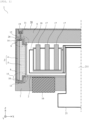
- FIG. 1 is a diagram showing a cross-sectional configuration example of a reagent cooler of an automated analyzer according to a first embodiment.
- FIG. 1 shows only a configuration of a reagent cooler 1 in a left side cross section of a rotation axis 211, which will be described later.
- an upper portion and a lower portion of the reagent cooler 1 are defined in a Z-axis direction in FIG. 1 .
- reagent bottles 17 provided inside the reagent cooler 1 are placed on a reagent disk 18.
- the reagent disk 18 is configured to be rotatable within an XY plane by a driving unit 21 about the rotation axis 211 (extending in a Z direction).
- a cooling jacket (also referred to as a reagent jacket) 2 is provided in a periphery (on a side surface) and a lower surface of the reagent disk 18.
- This cooling jacket 2 is cooled by a cooling device 16 such as a Peltier cooling unit attached to a lower surface of the reagent cooler 1.
- a material having relatively high thermal conductivity, such as copper or aluminum, is used for the cooling jacket 2 in order to conduct heat effectively.
- a lower side of the cooling jacket 2 is filled with a lower heat insulation material 7 such as a polystyrene foam to insulate heat from the outside.
- a resin frame 8 made of polypropylene or the like is provided on an outermost side of a side surface of the reagent cooler 1. Then, a vacuum heat insulation material 4 is fixed to the resin frame 8 with an adhesive or the like.
- An upper resin material 9 is provided on an upper portion of the vacuum heat insulation material 4, and a lower resin material 10 is provided on a lower portion of the vacuum heat insulation material 4.
- a portion between the vacuum heat insulation material 4 and the cooling jacket 2 and between the upper resin material 9 and the lower resin material 10 is filled with a heat insulation material 5 such as a urethane foam material.
- a combination of the vacuum heat insulation material 4 and the urethane foam material 5 is referred to as a peripheral heat insulation portion (peripheral heat insulation material) 3.
- the upper portion of the reagent cooler 1 is formed by an upper heat insulation material 6 such as polystyrene foam and a resin frame 11 such as polypropylene, and covered by an upper cover 50.
- a sealing material 12 (for example, silicon, modified silicon, urethane, acryl, polysulfide, and the like) is provided between the upper resin material 9 and the upper heat insulation material 6.
- a nut 20 is embedded in the upper resin material 9, and the upper cover 50 and the nut 20 are fixed by a bolt 19.
- the bolt 19 and the nut 20 can be made of a resin such as a fluororesin, considering an influence of heat leakage caused by heat conduction.
- a sealing material 13 is provided between the lower resin material 10 and the lower heat insulation material 7.
- a step 14 is provided between a lower side of the upper heat insulation material 6 and an upper side of the peripheral heat insulation portion (peripheral heat insulation material) 3.
- a step 15 is provided between an upper side of the lower heat insulation material 7 and a lower side of the peripheral heat insulation portion (peripheral heat insulation material) 3.
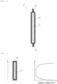
- FIG. 2 is a diagram showing a cross-sectional configuration example of the vacuum heat insulation material 4.
- FIG. 3 is a diagram showing thermal conductivity of the vacuum heat insulation material 4.
- the vacuum heat insulation material 4 is a heat insulation material formed of a core material 41 and an outer cover material 42 that wraps the core material 41 and is a composite material having a gas barrier property, and obtained by reducing a pressure inside the outer cover material 42 to a vacuum state.
- a core material 41 a fibrous material such as glass wool, a foam, or a powder material is used.
- the outer cover material 42 an aluminum deposition film or the like is used.
- Thermal conductivity of the outer cover material 42 is higher than that inside the vacuum. Therefore, as schematically shown in FIG. 3 , thermal conductivity of both end portions of the vacuum heat insulation material is high. Lugs 43 at both end portions in FIG. 2 (the vacuum heat insulation material is inevitably formed with lugs) are actually mounted in a folding manner, and the lugs are omitted in FIG. 3 . Since both end portions of the vacuum heat insulation material 4 have the high thermal conductivity in this manner, by providing the steps 14 and 15 and shifting positions of top and bottom end portions of the cooling jacket 2 and positions of the end portions of the vacuum heat insulation material 4 as described above, heat transferred through both end portions of the vacuum heat insulation material 4 (heat from the outside) can be reduced.
- FIG. 4 is a diagram showing a relationship (heat insulation performance) between cooling capacity and a temperature reduction amount when a top and bottom height of the cooling jacket 2 and a height of the end portions of the vacuum heat insulation material 4 are aligned (structure in the related art) and when the two heights are shifted (present embodiment).
- each of the cooling capacity and the temperature reduction amount is represented by a ratio to a reference.
- a structure of the present embodiment is capable of cooling the inside to a lower temperature with the same cooling capacity.
- the cooling capacity can be reduced. Since heat insulation performance of the peripheral heat insulation portion 3 is improved in this manner, a thickness of the peripheral heat insulation portion (peripheral heat insulation material) 3 can be reduced with the same internal temperature and cooling capacity. Specifically, the thickness of the peripheral heat insulation portion (peripheral heat insulation material) 3 can be reduced by about 10%.
- the structure of the present embodiment makes it possible to reduce a thickness of a peripheral heat insulation material (heat insulation material provided on a side surface of the reagent cooler 1), and therefore, it is possible to reduce a size of the reagent cooler and, furthermore, a size of the automated analyzer.
- FIG. 5 is a diagram showing a cross-sectional configuration example of the reagent cooler 1 of an automated analyzer according to a second embodiment. Portions common to the first embodiment are given the same numbers.
- the vacuum heat insulation material 4 is provided at a position away from the resin frame 8, and both sides of the vacuum heat insulation material 4 are filled with the urethane foam material 5 and a urethane foam material 51. Also in such a structure, the thickness of the heat insulation material on the side surface of the reagent cooler 1 can be reduced as in the first embodiment.
- each of the vacuum heat insulation materials provided on a side surface, a lower portion, the upper cover 50, and the like will be described as having a shape of being in close contact with the resin frame respectively, and as in the second embodiment, a structure in which the vacuum heat insulation material 4 is provided at a position away from the resin frame and both sides of the vacuum heat insulation material 4 are filled with the urethane foam material 51 also can be employed. Also in this way, thicknesses of the heat insulation materials on the side surface, a lower portion, and the upper portion can be reduced as in the second embodiment.
- FIG. 6 is a diagram showing a cross-sectional configuration example of the reagent cooler 1 of an automated analyzer according to a third embodiment. Portions common to the first embodiment are given the same numbers.
- a resin frame 80 of the reagent cooler 1 according to the third embodiment is configured by extending a lower side portion of the resin frame 8 shown in the first embodiment.
- the resin frame 80 can be manufactured by integrally molding a side surface portion and a lower side portion, or by joining these portions with an adhesive or the like.
- a resin frame 23 is connected to the resin frame 80 at a portion where the cooling device 16 is not provided, and has a structure surrounding a periphery of the cooling device 16.
- a urethane foam material By injecting a urethane foam material into a side surface portion and a lower side portion of the cooling jacket 2 and foaming, a structure is obtained in which a side surface heat insulation portion and a lower side heat insulation portion are integrated.
- the urethane foam material 5 and a urethane foam material 22 are injected together into the resin frame 23 and connected at the portion where the cooling device 16 is not provided.
- a length of the vacuum heat insulation material 4 is set longer than a length of the vacuum heat insulation material in the first embodiment, and a position of a lower side portion of the vacuum heat insulation material 4 becomes a position below the cooling jacket 2.
- the step 14 is provided on the upper side of the peripheral heat insulation portion (peripheral heat insulation material) 3 as in the first embodiment. In this manner, both end portions of the vacuum heat insulation material 4 (which have a higher thermal conductivity than that of a central portion of the vacuum heat insulation material 4) can be kept away from the cooling jacket 2.
- a joint portion between the side surface heat insulation material and the lower side heat insulation material can be eliminated, and therefore, heat leakage from the joint portion can be prevented.
- the portion of the side surface heat insulation material can be made thinner, it is possible to further reduce the size of the reagent cooler.
- FIG. 7 is a diagram showing a cross-sectional configuration example of the reagent cooler 1 of an automated analyzer according to a fourth embodiment.
- vacuum heat insulation materials 24 and 25 are attached to a lower side portion in addition to a side surface.
- the vacuum heat insulation material 24 is fixed to a lower portion of the resin frame 80 by an adhesive or the like, and the vacuum heat insulation material 25 is fixed to the resin frame 23 by an adhesive or the like, respectively.
- a vacuum heat insulation material 26 is attached to the upper cover 50.
- the vacuum heat insulation material 26 is fixed to the resin frame 11 by an adhesive or the like.
- the upper heat insulation material 6 may be manufactured using a urethane foam material like the other heat insulation portions.
- An end portion 27 of the vacuum heat insulation material 24 of the lower side portion is provided so as to be located further outside an outer surface of the cooling jacket 2.
- an end portion 28 of the vacuum heat insulation material 26 attached to the upper cover 50 is provided so as to be located further outside the outer surface of the cooling jacket 2.
- the vacuum heat insulation materials are also attached to the lower side portion and the upper cover portion, and the end portions of these vacuum heat insulation materials are provided so as to be located further outside the outer surface of the cooling jacket 2.
- the heat insulation performance is improved, a heat insulation material 22 of the lower side portion and the upper heat insulation material 6 of the upper cover portion can be made thinner, and therefore, the size of the reagent cooler can be further reduced.
- FIG. 8 is a diagram showing a cross-sectional configuration example of the reagent cooler 1 of an automated analyzer according to a fifth embodiment.
- a resin flange 29 for fixing the upper cover 50 is provided on the resin frame 11 and a flange 30 is provided on an upper portion of the resin frame 8.
- the upper cover 50 is fixed by the bolt 19 and the nut 20.
- the thickness of the heat insulation material is reduced by using a vacuum heat insulation material having a high heat insulation efficiency.
- the heat insulation efficiency at the end portions is lower than that at the other portions. Therefore, when the vacuum heat insulation materials (vacuum heat insulation materials 4, 24 to 26) are disposed in a periphery (on a side surface, or/and upper and lower portions) of the reagent cooler 1, the end portions of the vacuum heat insulation materials are disposed at positions shifted from the top and bottom end portions and a side surface end portion of the cooling jacket 2 such that distances between the end portions of the vacuum heat insulation materials and the cooling jacket 2 are taken as much as possible.
- the heat insulation materials of the reagent cooler 1 can be made thinner than that of a configuration in the related art, and therefore, the size of the reagent cooler 1 and, furthermore, the size of the automated analyzer can be reduced.
- the automated analyzer can be applied to devices that require reagents to be stored at a low temperature, such as an immunology analyzer and a biochemical analyzer.
Landscapes
- Chemical & Material Sciences (AREA)
- Health & Medical Sciences (AREA)
- Chemical Kinetics & Catalysis (AREA)
- Clinical Laboratory Science (AREA)
- Life Sciences & Earth Sciences (AREA)
- Physics & Mathematics (AREA)
- Analytical Chemistry (AREA)
- Biochemistry (AREA)
- General Health & Medical Sciences (AREA)
- General Physics & Mathematics (AREA)
- Immunology (AREA)
- Pathology (AREA)
- Medicinal Chemistry (AREA)
- Mechanical Engineering (AREA)
- Engineering & Computer Science (AREA)
- Automatic Analysis And Handling Materials Therefor (AREA)
Applications Claiming Priority (2)
| Application Number | Priority Date | Filing Date | Title |
|---|---|---|---|
| JP2020095589A JP7426904B2 (ja) | 2020-06-01 | 2020-06-01 | 自動分析装置 |
| PCT/JP2021/006095 WO2021245994A1 (ja) | 2020-06-01 | 2021-02-18 | 自動分析装置 |
Publications (2)
| Publication Number | Publication Date |
|---|---|
| EP4160216A1 true EP4160216A1 (de) | 2023-04-05 |
| EP4160216A4 EP4160216A4 (de) | 2024-05-22 |
Family
ID=78830787
Family Applications (1)
| Application Number | Title | Priority Date | Filing Date |
|---|---|---|---|
| EP21816944.9A Pending EP4160216A4 (de) | 2020-06-01 | 2021-02-18 | Automatisches analysegerät |
Country Status (5)
| Country | Link |
|---|---|
| US (1) | US12422445B2 (de) |
| EP (1) | EP4160216A4 (de) |
| JP (1) | JP7426904B2 (de) |
| CN (1) | CN115516316B (de) |
| WO (1) | WO2021245994A1 (de) |
Family Cites Families (29)
| Publication number | Priority date | Publication date | Assignee | Title |
|---|---|---|---|---|
| JPS5998287U (ja) * | 1982-12-22 | 1984-07-03 | 株式会社日立製作所 | 真空断熱材固定構造 |
| JPS6091174A (ja) * | 1983-10-24 | 1985-05-22 | 松下冷機株式会社 | 断熱箱体 |
| JPH11201379A (ja) * | 1998-01-13 | 1999-07-30 | Sanyo Electric Co Ltd | 真空断熱材およびその製造方法 |
| US6209343B1 (en) * | 1998-09-29 | 2001-04-03 | Life Science Holdings, Inc. | Portable apparatus for storing and/or transporting biological samples, tissues and/or organs |
| US7316123B2 (en) * | 1999-09-30 | 2008-01-08 | Gano & Gandy Industries, Inc. | Systems and methods for storing items with containers |
| JP4051355B2 (ja) * | 2004-03-31 | 2008-02-20 | 株式会社日立ハイテクノロジーズ | 試薬保冷装置及びそれを用いた自動分析装置 |
| JP4734149B2 (ja) * | 2006-03-14 | 2011-07-27 | 株式会社日立ハイテクノロジーズ | 自動分析装置 |
| JP4940032B2 (ja) * | 2007-06-29 | 2012-05-30 | 株式会社東芝 | 自動分析装置及びその試薬庫 |
| JP2009270857A (ja) * | 2008-05-01 | 2009-11-19 | Olympus Corp | 自動分析装置 |
| JP4367574B2 (ja) * | 2008-10-17 | 2009-11-18 | パナソニック株式会社 | 冷蔵庫 |
| JP2010159987A (ja) | 2009-01-06 | 2010-07-22 | Hitachi High-Technologies Corp | 自動分析装置 |
| JP2011191114A (ja) * | 2010-03-12 | 2011-09-29 | Sysmex Corp | 分析装置 |
| US8999241B2 (en) | 2011-03-16 | 2015-04-07 | Sysmex Corporation | Specimen analyzer |
| JP5753713B2 (ja) * | 2011-03-16 | 2015-07-22 | シスメックス株式会社 | 検体分析装置 |
| JP5737215B2 (ja) * | 2012-03-13 | 2015-06-17 | 株式会社島津製作所 | 試料冷却装置及びサンプリング装置 |
| JP6091825B2 (ja) * | 2012-09-25 | 2017-03-08 | 東芝ライフスタイル株式会社 | 冷蔵庫 |
| JP6173685B2 (ja) * | 2012-12-25 | 2017-08-02 | 東芝ライフスタイル株式会社 | 冷蔵庫 |
| JP6002641B2 (ja) * | 2013-08-20 | 2016-10-05 | 日立アプライアンス株式会社 | 真空断熱材及び冷蔵庫 |
| JP6132715B2 (ja) * | 2013-09-06 | 2017-05-24 | 三菱電機株式会社 | 真空断熱材の製造方法及び断熱箱 |
| JP2017508984A (ja) * | 2014-01-20 | 2017-03-30 | ブルックス オートメーション インコーポレイテッド | 持ち運び可能な低温ワークステーション |
| JP2015197280A (ja) * | 2014-04-03 | 2015-11-09 | 日立アプライアンス株式会社 | 冷蔵庫 |
| JP6560016B2 (ja) | 2015-04-27 | 2019-08-14 | キヤノンメディカルシステムズ株式会社 | 自動分析装置 |
| US11209344B2 (en) * | 2015-07-20 | 2021-12-28 | Brooks Automation, Inc. | Automated vault module |
| US11673142B2 (en) * | 2015-09-24 | 2023-06-13 | Liconic Ag | Device for the low-temperature storage and the handling of probe tubes in tube racks |
| JP7100985B2 (ja) * | 2018-01-25 | 2022-07-14 | シスメックス株式会社 | 検体測定装置および試薬庫内の空気の循環方法 |
| JP2019132499A (ja) | 2018-01-31 | 2019-08-08 | 日立グローバルライフソリューションズ株式会社 | 冷蔵庫 |
| JP7199911B2 (ja) * | 2018-10-29 | 2023-01-06 | キヤノンメディカルシステムズ株式会社 | 自動分析装置 |
| CN209480377U (zh) * | 2019-01-16 | 2019-10-11 | 田瑞 | 一种防化冷凝保护套 |
| US12196773B2 (en) * | 2019-04-18 | 2025-01-14 | Hitachi High-Tech Corporation | Automatic analysis device, cold storage, and method for cooling reagent in automatic analysis device |
-
2020
- 2020-06-01 JP JP2020095589A patent/JP7426904B2/ja active Active
-
2021
- 2021-02-18 US US17/922,684 patent/US12422445B2/en active Active
- 2021-02-18 EP EP21816944.9A patent/EP4160216A4/de active Pending
- 2021-02-18 WO PCT/JP2021/006095 patent/WO2021245994A1/ja not_active Ceased
- 2021-02-18 CN CN202180032662.5A patent/CN115516316B/zh active Active
Also Published As
| Publication number | Publication date |
|---|---|
| US20230266349A1 (en) | 2023-08-24 |
| CN115516316A (zh) | 2022-12-23 |
| EP4160216A4 (de) | 2024-05-22 |
| JP2021189068A (ja) | 2021-12-13 |
| WO2021245994A1 (ja) | 2021-12-09 |
| JP7426904B2 (ja) | 2024-02-02 |
| CN115516316B (zh) | 2025-11-11 |
| US12422445B2 (en) | 2025-09-23 |
Similar Documents
| Publication | Publication Date | Title |
|---|---|---|
| US11158461B2 (en) | Capacitor | |
| EP2315220A1 (de) | Reaktorkomponente und reaktor | |
| US20060000221A1 (en) | Insulated container with thermoelectric unit | |
| CN101669004A (zh) | 集装箱用制冷装置的壳体构造及其制造方法 | |
| US20110319269A1 (en) | Container for superconducting apparatus and superconducting apparatus | |
| US20150136788A1 (en) | Web insulation system, valve for a web insulation system, and a storage container using the web insulation system | |
| JP7728758B2 (ja) | 真空断熱容器本体、容器及び関連方法 | |
| US20200079575A1 (en) | Thermally insulated container | |
| US12422445B2 (en) | Automated analyzer | |
| JP2008306048A (ja) | 電子ユニット筐体 | |
| JP6089964B2 (ja) | 電力変換装置 | |
| CN113432357B (zh) | 冰箱以及制造方法 | |
| CN107035571B (zh) | 整合于发动机缸体/缸盖的冷却器用板 | |
| JP2013242100A (ja) | 冷蔵庫断熱箱体 | |
| US12119192B2 (en) | Hermetic terminal and contact device using the hermetic terminal | |
| JP2503637B2 (ja) | 冷凍装置用圧縮機 | |
| GB2089950A (en) | Thermally insulated containers | |
| EP2667198B1 (de) | Analysesystem | |
| EP1009039B1 (de) | Kühlvorrichtung für Supraleiter | |
| US12590675B2 (en) | Cryogenic tank device with heat exchanger | |
| EP3836174B1 (de) | Reaktor | |
| EP2620239B1 (de) | Wärmeableitendes Modul und Verfahren zu seiner Herstellung | |
| JP7405569B2 (ja) | リアクトル | |
| JP2008028308A (ja) | 車載用リアクトル | |
| CN223508843U (zh) | 一种吸气剂容器 |
Legal Events
| Date | Code | Title | Description |
|---|---|---|---|
| STAA | Information on the status of an ep patent application or granted ep patent |
Free format text: STATUS: THE INTERNATIONAL PUBLICATION HAS BEEN MADE |
|
| PUAI | Public reference made under article 153(3) epc to a published international application that has entered the european phase |
Free format text: ORIGINAL CODE: 0009012 |
|
| STAA | Information on the status of an ep patent application or granted ep patent |
Free format text: STATUS: REQUEST FOR EXAMINATION WAS MADE |
|
| 17P | Request for examination filed |
Effective date: 20221103 |
|
| AK | Designated contracting states |
Kind code of ref document: A1 Designated state(s): AL AT BE BG CH CY CZ DE DK EE ES FI FR GB GR HR HU IE IS IT LI LT LU LV MC MK MT NL NO PL PT RO RS SE SI SK SM TR |
|
| DAV | Request for validation of the european patent (deleted) | ||
| DAX | Request for extension of the european patent (deleted) | ||
| A4 | Supplementary search report drawn up and despatched |
Effective date: 20240423 |
|
| RIC1 | Information provided on ipc code assigned before grant |
Ipc: G01N 35/00 20060101AFI20240417BHEP |
|
| STAA | Information on the status of an ep patent application or granted ep patent |
Free format text: STATUS: EXAMINATION IS IN PROGRESS |
|
| 17Q | First examination report despatched |
Effective date: 20250331 |