EP4160322B1 - Bremsfeder für trägerwelle einer anzeige, uhrwerk mit dieser bremsfeder und einbauverfahren dieser bremsfeder - Google Patents
Bremsfeder für trägerwelle einer anzeige, uhrwerk mit dieser bremsfeder und einbauverfahren dieser bremsfeder Download PDFInfo
- Publication number
- EP4160322B1 EP4160322B1 EP21199688.9A EP21199688A EP4160322B1 EP 4160322 B1 EP4160322 B1 EP 4160322B1 EP 21199688 A EP21199688 A EP 21199688A EP 4160322 B1 EP4160322 B1 EP 4160322B1
- Authority
- EP
- European Patent Office
- Prior art keywords
- brake spring
- elastic
- elastic strip
- retaining element
- horological movement
- Prior art date
- Legal status (The legal status is an assumption and is not a legal conclusion. Google has not performed a legal analysis and makes no representation as to the accuracy of the status listed.)
- Active
Links
Images

Classifications
-
- G—PHYSICS
- G04—HOROLOGY
- G04B—MECHANICALLY-DRIVEN CLOCKS OR WATCHES; MECHANICAL PARTS OF CLOCKS OR WATCHES IN GENERAL; TIME PIECES USING THE POSITION OF THE SUN, MOON OR STARS
- G04B13/00—Gearwork
- G04B13/02—Wheels; Pinions; Spindles; Pivots
- G04B13/021—Wheels; Pinions; Spindles; Pivots elastic fitting with a spindle, axis or shaft
-
- G—PHYSICS
- G09—EDUCATION; CRYPTOGRAPHY; DISPLAY; ADVERTISING; SEALS
- G09B—EDUCATIONAL OR DEMONSTRATION APPLIANCES; APPLIANCES FOR TEACHING, OR COMMUNICATING WITH, THE BLIND, DEAF OR MUTE; MODELS; PLANETARIA; GLOBES; MAPS; DIAGRAMS
- G09B19/00—Teaching not covered by other main groups of this subclass
- G09B19/02—Counting; Calculating
-
- G—PHYSICS
- G04—HOROLOGY
- G04B—MECHANICALLY-DRIVEN CLOCKS OR WATCHES; MECHANICAL PARTS OF CLOCKS OR WATCHES IN GENERAL; TIME PIECES USING THE POSITION OF THE SUN, MOON OR STARS
- G04B1/00—Driving mechanisms
- G04B1/10—Driving mechanisms with mainspring
- G04B1/16—Barrels; Arbors; Barrel axles
-
- G—PHYSICS
- G04—HOROLOGY
- G04B—MECHANICALLY-DRIVEN CLOCKS OR WATCHES; MECHANICAL PARTS OF CLOCKS OR WATCHES IN GENERAL; TIME PIECES USING THE POSITION OF THE SUN, MOON OR STARS
- G04B31/00—Bearings; Point suspensions or counter-point suspensions; Pivot bearings; Single parts therefor
-
- G—PHYSICS
- G04—HOROLOGY
- G04B—MECHANICALLY-DRIVEN CLOCKS OR WATCHES; MECHANICAL PARTS OF CLOCKS OR WATCHES IN GENERAL; TIME PIECES USING THE POSITION OF THE SUN, MOON OR STARS
- G04B35/00—Adjusting the gear train, e.g. the backlash of the arbors, depth of meshing of the gears
Definitions
- the shape of the housing 124 defined by the jaw may be different from that described previously.
- the brake spring 10 is linked to the structure 21 of the watch movement 20 without any degree of freedom.
- the cooperation by elastic fitting is reversible, so that it is possible to remove the brake spring 10 from the structure 21 of the watch movement 20, for example to carry out a maintenance operation on said watch movement 20.
- the attachment member 23 is formed by two projecting pieces extending perpendicularly relative to a plane formed by the structure 21.
- Such protruding parts can be formed by tenons or pins.
- the projecting parts each comprise, at their free end, a radial collar 230 arranged opposite each of the parts 121 and 122 of the jaw when the brake spring 10 is fixed to said structure 21.
- This collar 230 advantageously ensures the blocking of any translational mobility of the brake spring 10 along an axis perpendicular to the plane formed by the structure 21, apart from mechanical clearances.
- the collars 230 prevent the brake spring 10 from becoming detached from the projecting parts in the event of a possible shock to the watch.
- This feature helps to ensure that the brake spring 10 is held in position on the watch movement 20.
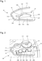
- the elastic blade 11 and the retaining element 13 are preferably arranged on either side of the elastic fitting member 12, as shown in the figures 1 to 4 in a preferred embodiment of the present invention.
- the elastic blade 11 extends from the first end of one of the parts 122 of the jaw and opposite the opening 125 of the housing 124 of the jaw, as visible in the figures 1 to 4 .
- the elastic blade 11 comprises a proximal portion 110 by which it is connected to the jaw and a distal portion 111, by which it cooperates with the retaining element 13 when it occupies the first position, and by which it is intended to apply a radial force against the shaft 22 carrying the display when it occupies the second position.
- proximal 110 and distal 111 portions are connected to each other by an intermediate portion 112 extending opposite the opening 125.
- proximal 110, intermediate 112 and distal 111 portions are bent relative to each other so that the distal 111 and proximal 110 portions are substantially parallel to each other when the elastic blade 11 is in the first position.
- the force applied against the shaft 22 has a main component whose direction is perpendicular to the longitudinal axis along which the housing 124 of the jaw extends, and coincides substantially with the first end of the parts 121 and 122, which helps to guarantee the good holding of the fixing of the jaw on the structure 21.
- the retaining element 13 is preferably formed by a hook configured to cooperate with the free end of the elastic blade 11. It is therefore understood that the hook extends from the first end of one of the parts 121, opposite the proximal portion 110 of the elastic blade 11.
- the structure 21 advantageously comprises a through orifice 210, for example of oblong shape, arranged to open opposite the elastic blade 11 when it is in the first position. Such an arrangement makes it possible to exert a force on the elastic blade 11 tending to release it from the hook with a tool engaged through said orifice 210, as described in more detail below.
- the fixing step comprises a positioning operation in which the brake spring 10 is arranged against the structure 21 of the watch movement 20, as shown in the Figure 2 , one of the projecting parts being arranged in the housing 124 formed by the jaw and the other being arranged between the intermediate portion 112 of the elastic blade 11 and the opening 125 of the housing 124 of the jaw.
- the fixing step then comprises a fitting operation in which the brake spring 10 is moved in translation along the longitudinal axis of the housing 124 so that one of the projecting parts is arranged against the bottom 123 of the housing 124 and the other is arranged against the narrow portion 126 thereof.
- the brake spring 10 can be produced by any suitable manufacturing method, such as machining, casting or additive manufacturing.
- the arrangement of the elastic blade 11 relative to the elastic fitting member 12 could be different from that described above and shown in the figures 1 to 4 .
Landscapes
- Physics & Mathematics (AREA)
- General Physics & Mathematics (AREA)
- Business, Economics & Management (AREA)
- Engineering & Computer Science (AREA)
- Entrepreneurship & Innovation (AREA)
- Educational Administration (AREA)
- Educational Technology (AREA)
- Theoretical Computer Science (AREA)
- Springs (AREA)
- Braking Arrangements (AREA)
Claims (16)
- Bremsfeder (10) zum Aufbringen einer Radialkraft gegen eine Welle (22), die eine Uhrenanzeige trägt, umfassend eine elastische Klinge (11), ein elastisches Gehäuseelement (12), das dazu geeignet ist, an einer Aufhängevorrichtung (23) einer Struktur (21) eines Uhrwerks (20) befestigt zu werden, und ein Halteelement (13) der elastischen Klinge (11), das so konfiguriert ist, dass es mit der elastischen Klinge (11) zusammenarbeitet, um sie in einer ersten Position zu halten, wobei die elastische Klinge (11) von der Halterung (13) gelöst werden kann, um eine zweite Position unter der Einwirkung einer elastischen Rückstellkraft einzunehmen, in der sie in der Lage ist, eine resultierende Radialkraft gegen die Welle (22) aufzubringen, die eine Anzeige trägt.
- Bremsfeder (10) nach Anspruch 1, wobei das elastische Gehäuseelement (12) eine Spannvorrichtung aufweist, die aus zwei Teilen (121, 122) besteht, die einen Sitz (124) definieren, und die sich jeweils zwischen einem ersten Ende, durch das die Teile (121, 122) verbunden sind, und einem Boden (123) des Sitzes (124), und einem zweiten Ende, durch das sie eine Öffnung (125) dieses Sitzes (124) bilden, erstrecken.
- Bremsfeder (10) nach Anspruch 2, wobei mindestens eines der Teile (121, 122) so ausgebildet ist, dass das Gehäuse (124) an seiner Öffnung (125) einen schmalen Abschnitt (126) aufweist, der zur Aufnahme der Aufhängungsvorrichtung (23) am Anschlag angepasst ist, sodass diese Bremsfeder (10) an der Struktur (21) eines Uhrwerks (20) befestigt werden kann.
- Bremsfeder (10) nach einem der Ansprüche 2 oder 3, bei der die Öffnung (125) ausgeweitet ist.
- Bremsfeder (10) nach einem der Ansprüche 2 bis 4, wobei sich die elastische Klinge (11) am ersten Ende eines der Teile (121, 122) der Spannvorrichtung und im Hinblick auf die Öffnung (125) der Spannvorrichtung erstreckt.
- Bremsfeder (10) nach Anspruch 5, bei der die elastische Klinge (11) einen proximalen Abschnitt (110) umfasst, durch den sie mit der Spannvorrichtung verbunden ist, einen distalen Abschnitt (111), durch den sie mit dem Halteelement (13) zusammenwirkt, wenn sie die erste Position innehat, und wobei sie beim Einnehmen der zweiten Stellung eine Radialkraft gegen die Welle (22) aufbringen soll, wobei die proximalen (110) und distalen (111) Abschnitte über einen Zwischenabschnitt (112) miteinander verbunden sind, der sich gegenüber der Öffnung (125) erstreckt.
- Bremsfeder (10) nach Anspruch 5 oder 6, wobei die elastische Klinge (11) und das Halteelement (13) auf beiden Seiten der Spannvorrichtung bzw. an jedem der Teile (121, 122) davon angeordnet sind.
- Bremsfeder (10) nach einem der Ansprüche 1 bis 7, wobei das Halteelement (13) durch einen Haken gebildet wird, der für das Zusammenwirken mit dem freien Ende der elastischen Klinge (11) bestimmt ist.
- Uhrwerk (20), dadurch gekennzeichnet, dass es eine Bremsfeder (10) nach einem der Ansprüche 1 bis 8 und eine Struktur (21) mit einer Aufhängevorrichtung (23) aufweist, mit der das elastische Gehäuseelement (12) so arbeitet, dass die Bremsfeder (10) an dieser Struktur (21) ohne Rückzugsminderung befestigt werden kann, und zwar bei Benutzung der zweiten Klinge (11).
- Uhrwerk (20) nach Anspruch 9, wobei die Struktur (21) eine Durchgangsbohrung (210) aufweist, die so angeordnet ist, dass sie sich vor der elastischen Klinge (11) öffnet, wenn sie die erste Position einnimmt.
- Uhrwerk (20) nach einem der Ansprüche 9 oder 10, bei der die Aufhängevorrichtung (23) am freien Ende einen vor der Bremsfeder (10) angeordneten radialen Flansch (230) aufweist.
- Uhrwerk (20) nach einem der Ansprüche 9 bis 11, wobei die Aufhängevorrichtung (23) aus zwei vorspringenden Teilen ausgebildet ist, die sich senkrecht zu einer durch die Struktur (21) gebildeten Ebene erstrecken.
- Uhrwerk (20) nach Anspruch 12, umfassend eine Bremsfeder (10) nach Anspruch 3, wobei eines der hervorstehenden Teile in einem Anschlag gegen die Teile (121, 122) des Achsschenkels an der schmalen Stelle (126) angeordnet ist, während das andere hervorstehende Teil in einem Anschlag gegen den Boden (123) des Sitzes (124) angeordnet ist.
- Verfahren zum Einbau einer Bremsfeder (10) nach einem der Ansprüche 1 bis 8 an einer Struktur (21) eines Uhrwerks (20) nach einem der Ansprüche 9 bis 13, dadurch gekennzeichnet, dass es die folgenden aufeinanderfolgenden Schritte umfasst:- Befestigung der Bremsfeder (10) an der Struktur (21) des Uhrwerks (20);- Halten der elastischen Klinge (11) in einer ersten Position, wobei die elastische Klinge (11) so angeordnet ist, dass sie mit dem Halteelement (13) zusammenwirkt;- Eingriff der Welle (22) durch eine Öffnung der Struktur (21);- Lösen der elastischen Klinge (11) vom Halteelement (13) so, dass die elastische Klinge (11) eine zweite Position einnimmt, in der sie eine radiale Kraft gegen die Welle (22) ausübt, die eine Uhrwerkanzeige (20) trägt.
- Verfahren nach Anspruch 14, wobei der Befestigungsschritt einen Positioniervorgang umfasst, bei dem die Bremsfeder (10) gegen die Struktur (21) des Uhrwerks (20) angeordnet ist, und einen Gehäuseschritt, bei dem die Bremsfeder (10) so gegen die Struktur (21) bewegt wird, dass das elastische Gehäuseelement (12) mit der Aufhängevorrichtung (23) zusammenwirkt.
- Verfahren nach einem der Ansprüche 13 bis 15, bei dem der Freigabeschritt durch Einführen eines Werkzeugs durch eine Öffnung (210) in die Struktur (21) des Uhrwerks (20), die zur elastischen Klinge führt (11), durchgeführt wird, damit dieses Werkzeug eine Kraft auf diese Klinge ausübt, die dazu bestimmt ist, es vom Halteelement (13) zu entfernen.
Priority Applications (6)
| Application Number | Priority Date | Filing Date | Title |
|---|---|---|---|
| EP21199688.9A EP4160322B1 (de) | 2021-09-29 | 2021-09-29 | Bremsfeder für trägerwelle einer anzeige, uhrwerk mit dieser bremsfeder und einbauverfahren dieser bremsfeder |
| US17/863,664 US20230098943A1 (en) | 2021-09-29 | 2022-07-13 | Brake spring for supporting arbor of a display, horological movement comprising said brake spring and method for installing said brake spring |
| KR1020220097476A KR102680789B1 (ko) | 2021-09-29 | 2022-08-04 | 디스플레이의 지지 아버용의 브레이크 스프링, 이 브레이크 스프링을 포함하는 측시 무브먼트 및 이 브레이크 스프링의 설치 방법 |
| JP2022128601A JP7438292B2 (ja) | 2021-09-29 | 2022-08-12 | ディスプレー要素のアーバーを支えるための制限用ばね、制限用ばねを備える計時器用ムーブメント、及び制限用ばねを設置する方法 |
| CN202222594021.3U CN218957032U (zh) | 2021-09-29 | 2022-09-29 | 用于显示装置的支撑心轴的制动弹簧、包括制动弹簧的钟表机芯 |
| CN202211199211.3A CN115877690B (zh) | 2021-09-29 | 2022-09-29 | 用于显示装置的支撑心轴的制动弹簧、包括制动弹簧的钟表机芯和安装制动弹簧的方法 |
Applications Claiming Priority (1)
| Application Number | Priority Date | Filing Date | Title |
|---|---|---|---|
| EP21199688.9A EP4160322B1 (de) | 2021-09-29 | 2021-09-29 | Bremsfeder für trägerwelle einer anzeige, uhrwerk mit dieser bremsfeder und einbauverfahren dieser bremsfeder |
Publications (2)
| Publication Number | Publication Date |
|---|---|
| EP4160322A1 EP4160322A1 (de) | 2023-04-05 |
| EP4160322B1 true EP4160322B1 (de) | 2025-06-25 |
Family
ID=78134796
Family Applications (1)
| Application Number | Title | Priority Date | Filing Date |
|---|---|---|---|
| EP21199688.9A Active EP4160322B1 (de) | 2021-09-29 | 2021-09-29 | Bremsfeder für trägerwelle einer anzeige, uhrwerk mit dieser bremsfeder und einbauverfahren dieser bremsfeder |
Country Status (5)
| Country | Link |
|---|---|
| US (1) | US20230098943A1 (de) |
| EP (1) | EP4160322B1 (de) |
| JP (1) | JP7438292B2 (de) |
| KR (1) | KR102680789B1 (de) |
| CN (2) | CN115877690B (de) |
Families Citing this family (2)
| Publication number | Priority date | Publication date | Assignee | Title |
|---|---|---|---|---|
| EP4160322B1 (de) * | 2021-09-29 | 2025-06-25 | ETA SA Manufacture Horlogère Suisse | Bremsfeder für trägerwelle einer anzeige, uhrwerk mit dieser bremsfeder und einbauverfahren dieser bremsfeder |
| EP4462193B1 (de) * | 2023-05-10 | 2026-01-14 | ETA SA Manufacture Horlogère Suisse | Mechanisches uhrwerk, das ein bewegliches element umfasst, das ein anzeigeelement mit einer bremsvorrichtung umfasst |
Family Cites Families (15)
| Publication number | Priority date | Publication date | Assignee | Title |
|---|---|---|---|---|
| US5155712A (en) | 1992-04-20 | 1992-10-13 | Timex Corporation | Wheel and pinion assembly with friction drive/slip coupling for a timepiece |
| JP2006242793A (ja) | 2005-03-04 | 2006-09-14 | Seiko Epson Corp | 時計 |
| US7597471B2 (en) * | 2005-11-24 | 2009-10-06 | Vaucher Manufacture Fleurier S.A. | Time piece chronograph clockwork movement |
| CH700811B1 (fr) * | 2006-06-06 | 2010-10-29 | Patek Philippe Sa Geneve | Pièce en matériau fragile, notamment en silicium. |
| DE602007004446D1 (de) | 2007-04-18 | 2010-03-11 | Eta Sa Mft Horlogere Suisse | Direktimpulshemmung für Uhren |
| EP2706416B1 (de) * | 2012-09-07 | 2015-11-18 | The Swatch Group Research and Development Ltd | Flexibler Anker mit konstanter Kraft |
| EP2977833B1 (de) * | 2014-07-21 | 2018-01-03 | Montres Breguet SA | Präzise Positionierung der Brücke einer Uhr |
| EP2977829B1 (de) * | 2014-07-24 | 2017-07-12 | ETA SA Manufacture Horlogère Suisse | Anordnung mit beweglichem Bremselement einer Uhr |
| CH712012A1 (fr) * | 2016-01-14 | 2017-07-14 | Richemont Int Sa | Mouvement horloger à mécanisme d'affichage sautant. |
| EP3246764B1 (de) * | 2016-05-18 | 2019-01-23 | Montres Breguet S.A. | Stossdämpfende vorrichtung für uhrwerk |
| EP3396470B1 (de) * | 2017-04-24 | 2020-01-01 | ETA SA Manufacture Horlogère Suisse | Mechanische bremsvorrichtung für drehteil einer uhr |
| EP3561606B1 (de) * | 2018-04-27 | 2022-01-26 | The Swatch Group Research and Development Ltd | Stossdämpfungsschutz eines resonators mit rcc-schwenkfedern |
| EP3719583B1 (de) * | 2019-04-03 | 2021-11-10 | ETA SA Manufacture Horlogère Suisse | Mechanische bremsvorrichtung für triebfeder einer uhr |
| EP3770696B1 (de) * | 2019-07-23 | 2021-12-01 | Omega SA | Anschlagkäfig für uhr mit aufzugstift und anschlagstift |
| EP4160322B1 (de) * | 2021-09-29 | 2025-06-25 | ETA SA Manufacture Horlogère Suisse | Bremsfeder für trägerwelle einer anzeige, uhrwerk mit dieser bremsfeder und einbauverfahren dieser bremsfeder |
-
2021
- 2021-09-29 EP EP21199688.9A patent/EP4160322B1/de active Active
-
2022
- 2022-07-13 US US17/863,664 patent/US20230098943A1/en active Pending
- 2022-08-04 KR KR1020220097476A patent/KR102680789B1/ko active Active
- 2022-08-12 JP JP2022128601A patent/JP7438292B2/ja active Active
- 2022-09-29 CN CN202211199211.3A patent/CN115877690B/zh active Active
- 2022-09-29 CN CN202222594021.3U patent/CN218957032U/zh not_active Withdrawn - After Issue
Also Published As
| Publication number | Publication date |
|---|---|
| US20230098943A1 (en) | 2023-03-30 |
| CN115877690A (zh) | 2023-03-31 |
| EP4160322A1 (de) | 2023-04-05 |
| KR102680789B1 (ko) | 2024-07-02 |
| CN115877690B (zh) | 2026-02-27 |
| JP7438292B2 (ja) | 2024-02-26 |
| CN218957032U (zh) | 2023-05-02 |
| JP2023050100A (ja) | 2023-04-10 |
| KR20230046201A (ko) | 2023-04-05 |
Similar Documents
| Publication | Publication Date | Title |
|---|---|---|
| CH705276B1 (fr) | Organe d'entraînement et de transmission pour un échappement à ancre, plateau et échappement en étant équipés, et pièce d'horlogerie les comportant. | |
| EP2115537B1 (de) | Zeitmessgerät mit einem mechanismus zum betrieb einer vorrichtung zur anzeige eines zeitbezogenen wertes | |
| EP3499319B1 (de) | Kupplungswippe und kupplungsvorrichtung für uhrmechanismus | |
| EP2977829B1 (de) | Anordnung mit beweglichem Bremselement einer Uhr | |
| CH699680B1 (fr) | Dispositif de fixation d'un mobile fragile sur un élément de support. | |
| EP2799937B1 (de) | Dämpfungskörper eines Unruh-Oszillators einer Uhr | |
| EP4160322A1 (de) | Bremsfeder für trägerwelle einer anzeige, uhrwerk mit dieser bremsfeder und einbauverfahren dieser bremsfeder | |
| EP3032354B1 (de) | Befestigungssystem einer spiralfeder | |
| EP2977833B1 (de) | Präzise Positionierung der Brücke einer Uhr | |
| EP3032353B1 (de) | Ausbaubarer Spiralklötzchenträger | |
| EP2075652B1 (de) | Antriebs- und Übertragungsorgan für einen Hemmungsmechanimus, damit ausgestattete Platte und Hemmung und mit diesen ausgestattetes Uhrwerk | |
| EP3179315B1 (de) | Spiralklötzchenträger mit gesicherter montage | |
| EP4078297A1 (de) | Uhranzeigemechanismus | |
| CH719005A2 (fr) | Ressort frein pour arbre porteur d'un afficheur, mouvement horloger comprenant un tel ressort frein et procédé d'installation du ressort frein. | |
| EP3179314B1 (de) | Spiralklötzchenträger mit vereinfachter montage | |
| EP3779606B1 (de) | Armbanduhr mit automatischem aufzug | |
| CH706108A2 (fr) | Dispositif stop-secondes simplifié pour mouvement horloger. | |
| CH716774B9 (fr) | Dispositif horloger de couplage et d'indexation. | |
| CH719140A1 (fr) | Dispositif d'indexation pour un mécanisme d'horlogerie. | |
| CH713999A1 (fr) | Composant horloger destiné à être fixé sur un axe. | |
| EP1960846B1 (de) | Uhrwerk | |
| EP3714336B1 (de) | Halterung eines mobilgeräts mit einer anzeigescheibe | |
| EP4579360A1 (de) | Haltevorrichtung für ein mobiles gerät | |
| EP2689294B1 (de) | Brücke und uhrwerk sowie uhr mit einer solchen brücke | |
| EP3923086A1 (de) | Antriebsmodul für ein uhrwerk |
Legal Events
| Date | Code | Title | Description |
|---|---|---|---|
| PUAI | Public reference made under article 153(3) epc to a published international application that has entered the european phase |
Free format text: ORIGINAL CODE: 0009012 |
|
| STAA | Information on the status of an ep patent application or granted ep patent |
Free format text: STATUS: THE APPLICATION HAS BEEN PUBLISHED |
|
| AK | Designated contracting states |
Kind code of ref document: A1 Designated state(s): AL AT BE BG CH CY CZ DE DK EE ES FI FR GB GR HR HU IE IS IT LI LT LU LV MC MK MT NL NO PL PT RO RS SE SI SK SM TR |
|
| P01 | Opt-out of the competence of the unified patent court (upc) registered |
Effective date: 20230701 |
|
| STAA | Information on the status of an ep patent application or granted ep patent |
Free format text: STATUS: REQUEST FOR EXAMINATION WAS MADE |
|
| 17P | Request for examination filed |
Effective date: 20231005 |
|
| RBV | Designated contracting states (corrected) |
Designated state(s): AL AT BE BG CH CY CZ DE DK EE ES FI FR GB GR HR HU IE IS IT LI LT LU LV MC MK MT NL NO PL PT RO RS SE SI SK SM TR |
|
| REG | Reference to a national code |
Ref country code: DE Ref legal event code: R079 Free format text: PREVIOUS MAIN CLASS: G04B0013020000 Ipc: G04B0035000000 Ref country code: DE Ref legal event code: R079 Ref document number: 602021032738 Country of ref document: DE Free format text: PREVIOUS MAIN CLASS: G04B0013020000 Ipc: G04B0035000000 |
|
| GRAP | Despatch of communication of intention to grant a patent |
Free format text: ORIGINAL CODE: EPIDOSNIGR1 |
|
| STAA | Information on the status of an ep patent application or granted ep patent |
Free format text: STATUS: GRANT OF PATENT IS INTENDED |
|
| RIC1 | Information provided on ipc code assigned before grant |
Ipc: G04B 13/02 20060101ALI20250213BHEP Ipc: G04B 35/00 20060101AFI20250213BHEP |
|
| INTG | Intention to grant announced |
Effective date: 20250304 |
|
| GRAS | Grant fee paid |
Free format text: ORIGINAL CODE: EPIDOSNIGR3 |
|
| GRAA | (expected) grant |
Free format text: ORIGINAL CODE: 0009210 |
|
| STAA | Information on the status of an ep patent application or granted ep patent |
Free format text: STATUS: THE PATENT HAS BEEN GRANTED |
|
| AK | Designated contracting states |
Kind code of ref document: B1 Designated state(s): AL AT BE BG CH CY CZ DE DK EE ES FI FR GB GR HR HU IE IS IT LI LT LU LV MC MK MT NL NO PL PT RO RS SE SI SK SM TR |
|
| REG | Reference to a national code |
Ref country code: GB Ref legal event code: FG4D Free format text: NOT ENGLISH |
|
| REG | Reference to a national code |
Ref country code: CH Ref legal event code: EP |
|
| REG | Reference to a national code |
Ref country code: CH Ref legal event code: EP |
|
| REG | Reference to a national code |
Ref country code: IE Ref legal event code: FG4D Free format text: LANGUAGE OF EP DOCUMENT: FRENCH |
|
| REG | Reference to a national code |
Ref country code: DE Ref legal event code: R096 Ref document number: 602021032738 Country of ref document: DE |
|
| REG | Reference to a national code |
Ref country code: CH Ref legal event code: U11 Free format text: ST27 STATUS EVENT CODE: U-0-0-U10-U11 (AS PROVIDED BY THE NATIONAL OFFICE) Effective date: 20251001 |
|
| PG25 | Lapsed in a contracting state [announced via postgrant information from national office to epo] |
Ref country code: FI Free format text: LAPSE BECAUSE OF FAILURE TO SUBMIT A TRANSLATION OF THE DESCRIPTION OR TO PAY THE FEE WITHIN THE PRESCRIBED TIME-LIMIT Effective date: 20250625 |
|
| PGFP | Annual fee paid to national office [announced via postgrant information from national office to epo] |
Ref country code: DE Payment date: 20250820 Year of fee payment: 5 |
|
| REG | Reference to a national code |
Ref country code: LT Ref legal event code: MG9D |
|
| PG25 | Lapsed in a contracting state [announced via postgrant information from national office to epo] |
Ref country code: NO Free format text: LAPSE BECAUSE OF FAILURE TO SUBMIT A TRANSLATION OF THE DESCRIPTION OR TO PAY THE FEE WITHIN THE PRESCRIBED TIME-LIMIT Effective date: 20250925 Ref country code: GR Free format text: LAPSE BECAUSE OF FAILURE TO SUBMIT A TRANSLATION OF THE DESCRIPTION OR TO PAY THE FEE WITHIN THE PRESCRIBED TIME-LIMIT Effective date: 20250926 |
|
| PG25 | Lapsed in a contracting state [announced via postgrant information from national office to epo] |
Ref country code: BG Free format text: LAPSE BECAUSE OF FAILURE TO SUBMIT A TRANSLATION OF THE DESCRIPTION OR TO PAY THE FEE WITHIN THE PRESCRIBED TIME-LIMIT Effective date: 20250625 |
|
| PGFP | Annual fee paid to national office [announced via postgrant information from national office to epo] |
Ref country code: GB Payment date: 20250820 Year of fee payment: 5 |
|
| PG25 | Lapsed in a contracting state [announced via postgrant information from national office to epo] |
Ref country code: HR Free format text: LAPSE BECAUSE OF FAILURE TO SUBMIT A TRANSLATION OF THE DESCRIPTION OR TO PAY THE FEE WITHIN THE PRESCRIBED TIME-LIMIT Effective date: 20250625 |
|
| PGFP | Annual fee paid to national office [announced via postgrant information from national office to epo] |
Ref country code: AT Payment date: 20251020 Year of fee payment: 5 Ref country code: FR Payment date: 20250820 Year of fee payment: 5 |
|
| PG25 | Lapsed in a contracting state [announced via postgrant information from national office to epo] |
Ref country code: RS Free format text: LAPSE BECAUSE OF FAILURE TO SUBMIT A TRANSLATION OF THE DESCRIPTION OR TO PAY THE FEE WITHIN THE PRESCRIBED TIME-LIMIT Effective date: 20250925 |
|
| PG25 | Lapsed in a contracting state [announced via postgrant information from national office to epo] |
Ref country code: LV Free format text: LAPSE BECAUSE OF FAILURE TO SUBMIT A TRANSLATION OF THE DESCRIPTION OR TO PAY THE FEE WITHIN THE PRESCRIBED TIME-LIMIT Effective date: 20250625 |
|
| REG | Reference to a national code |
Ref country code: NL Ref legal event code: MP Effective date: 20250625 |
|
| PG25 | Lapsed in a contracting state [announced via postgrant information from national office to epo] |
Ref country code: NL Free format text: LAPSE BECAUSE OF FAILURE TO SUBMIT A TRANSLATION OF THE DESCRIPTION OR TO PAY THE FEE WITHIN THE PRESCRIBED TIME-LIMIT Effective date: 20250625 |
|
| PG25 | Lapsed in a contracting state [announced via postgrant information from national office to epo] |
Ref country code: PT Free format text: LAPSE BECAUSE OF FAILURE TO SUBMIT A TRANSLATION OF THE DESCRIPTION OR TO PAY THE FEE WITHIN THE PRESCRIBED TIME-LIMIT Effective date: 20251027 |
|
| REG | Reference to a national code |
Ref country code: AT Ref legal event code: MK05 Ref document number: 1807089 Country of ref document: AT Kind code of ref document: T Effective date: 20250625 |
|
| PG25 | Lapsed in a contracting state [announced via postgrant information from national office to epo] |
Ref country code: IS Free format text: LAPSE BECAUSE OF FAILURE TO SUBMIT A TRANSLATION OF THE DESCRIPTION OR TO PAY THE FEE WITHIN THE PRESCRIBED TIME-LIMIT Effective date: 20251025 |
|
| PG25 | Lapsed in a contracting state [announced via postgrant information from national office to epo] |
Ref country code: AT Free format text: LAPSE BECAUSE OF FAILURE TO SUBMIT A TRANSLATION OF THE DESCRIPTION OR TO PAY THE FEE WITHIN THE PRESCRIBED TIME-LIMIT Effective date: 20250625 Ref country code: SM Free format text: LAPSE BECAUSE OF FAILURE TO SUBMIT A TRANSLATION OF THE DESCRIPTION OR TO PAY THE FEE WITHIN THE PRESCRIBED TIME-LIMIT Effective date: 20250625 |
|
| PGFP | Annual fee paid to national office [announced via postgrant information from national office to epo] |
Ref country code: CH Payment date: 20251001 Year of fee payment: 5 |
|
| PG25 | Lapsed in a contracting state [announced via postgrant information from national office to epo] |
Ref country code: CZ Free format text: LAPSE BECAUSE OF FAILURE TO SUBMIT A TRANSLATION OF THE DESCRIPTION OR TO PAY THE FEE WITHIN THE PRESCRIBED TIME-LIMIT Effective date: 20250625 |
|
| PG25 | Lapsed in a contracting state [announced via postgrant information from national office to epo] |
Ref country code: PL Free format text: LAPSE BECAUSE OF FAILURE TO SUBMIT A TRANSLATION OF THE DESCRIPTION OR TO PAY THE FEE WITHIN THE PRESCRIBED TIME-LIMIT Effective date: 20250625 |
|
| PG25 | Lapsed in a contracting state [announced via postgrant information from national office to epo] |
Ref country code: EE Free format text: LAPSE BECAUSE OF FAILURE TO SUBMIT A TRANSLATION OF THE DESCRIPTION OR TO PAY THE FEE WITHIN THE PRESCRIBED TIME-LIMIT Effective date: 20250625 |
|
| PG25 | Lapsed in a contracting state [announced via postgrant information from national office to epo] |
Ref country code: SK Free format text: LAPSE BECAUSE OF FAILURE TO SUBMIT A TRANSLATION OF THE DESCRIPTION OR TO PAY THE FEE WITHIN THE PRESCRIBED TIME-LIMIT Effective date: 20250625 |
|
| PG25 | Lapsed in a contracting state [announced via postgrant information from national office to epo] |
Ref country code: ES Free format text: LAPSE BECAUSE OF FAILURE TO SUBMIT A TRANSLATION OF THE DESCRIPTION OR TO PAY THE FEE WITHIN THE PRESCRIBED TIME-LIMIT Effective date: 20250625 |
|
| PG25 | Lapsed in a contracting state [announced via postgrant information from national office to epo] |
Ref country code: RO Free format text: LAPSE BECAUSE OF FAILURE TO SUBMIT A TRANSLATION OF THE DESCRIPTION OR TO PAY THE FEE WITHIN THE PRESCRIBED TIME-LIMIT Effective date: 20250625 |
|
| PG25 | Lapsed in a contracting state [announced via postgrant information from national office to epo] |
Ref country code: DK Free format text: LAPSE BECAUSE OF FAILURE TO SUBMIT A TRANSLATION OF THE DESCRIPTION OR TO PAY THE FEE WITHIN THE PRESCRIBED TIME-LIMIT Effective date: 20250625 |
|
| PG25 | Lapsed in a contracting state [announced via postgrant information from national office to epo] |
Ref country code: IT Free format text: LAPSE BECAUSE OF FAILURE TO SUBMIT A TRANSLATION OF THE DESCRIPTION OR TO PAY THE FEE WITHIN THE PRESCRIBED TIME-LIMIT Effective date: 20250625 |
|
| PLBE | No opposition filed within time limit |
Free format text: ORIGINAL CODE: 0009261 |
|
| STAA | Information on the status of an ep patent application or granted ep patent |
Free format text: STATUS: NO OPPOSITION FILED WITHIN TIME LIMIT |
|
| REG | Reference to a national code |
Ref country code: CH Ref legal event code: L10 Free format text: ST27 STATUS EVENT CODE: U-0-0-L10-L00 (AS PROVIDED BY THE NATIONAL OFFICE) Effective date: 20260507 |