EP4160425B1 - Procédé de transmission de données, puce et dispositif - Google Patents
Procédé de transmission de données, puce et dispositif Download PDFInfo
- Publication number
- EP4160425B1 EP4160425B1 EP21837789.3A EP21837789A EP4160425B1 EP 4160425 B1 EP4160425 B1 EP 4160425B1 EP 21837789 A EP21837789 A EP 21837789A EP 4160425 B1 EP4160425 B1 EP 4160425B1
- Authority
- EP
- European Patent Office
- Prior art keywords
- queue
- network interface
- interface card
- context
- storage
- Prior art date
- Legal status (The legal status is an assumption and is not a legal conclusion. Google has not performed a legal analysis and makes no representation as to the accuracy of the status listed.)
- Active
Links
Images






Classifications
-
- G—PHYSICS
- G06—COMPUTING OR CALCULATING; COUNTING
- G06F—ELECTRIC DIGITAL DATA PROCESSING
- G06F15/00—Digital computers in general; Data processing equipment in general
- G06F15/16—Combinations of two or more digital computers each having at least an arithmetic unit, a program unit and a register, e.g. for a simultaneous processing of several programs
- G06F15/163—Interprocessor communication
- G06F15/173—Interprocessor communication using an interconnection network, e.g. matrix, shuffle, pyramid, star, snowflake
- G06F15/17306—Intercommunication techniques
- G06F15/17331—Distributed shared memory [DSM], e.g. remote direct memory access [RDMA]
-
- G—PHYSICS
- G06—COMPUTING OR CALCULATING; COUNTING
- G06F—ELECTRIC DIGITAL DATA PROCESSING
- G06F13/00—Interconnection of, or transfer of information or other signals between, memories, input/output devices or central processing units
- G06F13/14—Handling requests for interconnection or transfer
- G06F13/16—Handling requests for interconnection or transfer for access to memory bus
- G06F13/1605—Handling requests for interconnection or transfer for access to memory bus based on arbitration
- G06F13/161—Handling requests for interconnection or transfer for access to memory bus based on arbitration with latency improvement
-
- G—PHYSICS
- G06—COMPUTING OR CALCULATING; COUNTING
- G06F—ELECTRIC DIGITAL DATA PROCESSING
- G06F12/00—Accessing, addressing or allocating within memory systems or architectures
- G06F12/02—Addressing or allocation; Relocation
- G06F12/08—Addressing or allocation; Relocation in hierarchically structured memory systems, e.g. virtual memory systems
- G06F12/0802—Addressing of a memory level in which the access to the desired data or data block requires associative addressing means, e.g. caches
- G06F12/0844—Multiple simultaneous or quasi-simultaneous cache accessing
- G06F12/0846—Cache with multiple tag or data arrays being simultaneously accessible
-
- G—PHYSICS
- G06—COMPUTING OR CALCULATING; COUNTING
- G06F—ELECTRIC DIGITAL DATA PROCESSING
- G06F12/00—Accessing, addressing or allocating within memory systems or architectures
- G06F12/02—Addressing or allocation; Relocation
- G06F12/08—Addressing or allocation; Relocation in hierarchically structured memory systems, e.g. virtual memory systems
- G06F12/12—Replacement control
- G06F12/121—Replacement control using replacement algorithms
- G06F12/126—Replacement control using replacement algorithms with special data handling, e.g. priority of data or instructions, handling errors or pinning
-
- G—PHYSICS
- G06—COMPUTING OR CALCULATING; COUNTING
- G06F—ELECTRIC DIGITAL DATA PROCESSING
- G06F13/00—Interconnection of, or transfer of information or other signals between, memories, input/output devices or central processing units
- G06F13/10—Program control for peripheral devices
- G06F13/12—Program control for peripheral devices using hardware independent of the central processor, e.g. channel or peripheral processor
-
- G—PHYSICS
- G06—COMPUTING OR CALCULATING; COUNTING
- G06F—ELECTRIC DIGITAL DATA PROCESSING
- G06F13/00—Interconnection of, or transfer of information or other signals between, memories, input/output devices or central processing units
- G06F13/14—Handling requests for interconnection or transfer
- G06F13/16—Handling requests for interconnection or transfer for access to memory bus
- G06F13/1605—Handling requests for interconnection or transfer for access to memory bus based on arbitration
- G06F13/1642—Handling requests for interconnection or transfer for access to memory bus based on arbitration with request queuing
-
- G—PHYSICS
- G06—COMPUTING OR CALCULATING; COUNTING
- G06F—ELECTRIC DIGITAL DATA PROCESSING
- G06F13/00—Interconnection of, or transfer of information or other signals between, memories, input/output devices or central processing units
- G06F13/14—Handling requests for interconnection or transfer
- G06F13/16—Handling requests for interconnection or transfer for access to memory bus
- G06F13/18—Handling requests for interconnection or transfer for access to memory bus based on priority control
-
- G—PHYSICS
- G06—COMPUTING OR CALCULATING; COUNTING
- G06F—ELECTRIC DIGITAL DATA PROCESSING
- G06F13/00—Interconnection of, or transfer of information or other signals between, memories, input/output devices or central processing units
- G06F13/14—Handling requests for interconnection or transfer
- G06F13/20—Handling requests for interconnection or transfer for access to input/output bus
- G06F13/28—Handling requests for interconnection or transfer for access to input/output bus using burst mode transfer, e.g. direct memory access DMA, cycle steal
-
- G—PHYSICS
- G06—COMPUTING OR CALCULATING; COUNTING
- G06F—ELECTRIC DIGITAL DATA PROCESSING
- G06F3/00—Input arrangements for transferring data to be processed into a form capable of being handled by the computer; Output arrangements for transferring data from processing unit to output unit, e.g. interface arrangements
- G06F3/06—Digital input from, or digital output to, record carriers, e.g. RAID, emulated record carriers or networked record carriers
- G06F3/0601—Interfaces specially adapted for storage systems
- G06F3/0602—Interfaces specially adapted for storage systems specifically adapted to achieve a particular effect
- G06F3/061—Improving I/O performance
-
- G—PHYSICS
- G06—COMPUTING OR CALCULATING; COUNTING
- G06F—ELECTRIC DIGITAL DATA PROCESSING
- G06F3/00—Input arrangements for transferring data to be processed into a form capable of being handled by the computer; Output arrangements for transferring data from processing unit to output unit, e.g. interface arrangements
- G06F3/06—Digital input from, or digital output to, record carriers, e.g. RAID, emulated record carriers or networked record carriers
- G06F3/0601—Interfaces specially adapted for storage systems
- G06F3/0628—Interfaces specially adapted for storage systems making use of a particular technique
- G06F3/0655—Vertical data movement, i.e. input-output transfer; data movement between one or more hosts and one or more storage devices
- G06F3/0659—Command handling arrangements, e.g. command buffers, queues, command scheduling
-
- G—PHYSICS
- G06—COMPUTING OR CALCULATING; COUNTING
- G06F—ELECTRIC DIGITAL DATA PROCESSING
- G06F3/00—Input arrangements for transferring data to be processed into a form capable of being handled by the computer; Output arrangements for transferring data from processing unit to output unit, e.g. interface arrangements
- G06F3/06—Digital input from, or digital output to, record carriers, e.g. RAID, emulated record carriers or networked record carriers
- G06F3/0601—Interfaces specially adapted for storage systems
- G06F3/0668—Interfaces specially adapted for storage systems adopting a particular infrastructure
- G06F3/067—Distributed or networked storage systems, e.g. storage area networks [SAN], network attached storage [NAS]
-
- H—ELECTRICITY
- H04—ELECTRIC COMMUNICATION TECHNIQUE
- H04L—TRANSMISSION OF DIGITAL INFORMATION, e.g. TELEGRAPHIC COMMUNICATION
- H04L47/00—Traffic control in data switching networks
- H04L47/10—Flow control; Congestion control
- H04L47/24—Traffic characterised by specific attributes, e.g. priority or QoS
- H04L47/245—Traffic characterised by specific attributes, e.g. priority or QoS using preemption
-
- H—ELECTRICITY
- H04—ELECTRIC COMMUNICATION TECHNIQUE
- H04L—TRANSMISSION OF DIGITAL INFORMATION, e.g. TELEGRAPHIC COMMUNICATION
- H04L67/00—Network arrangements or protocols for supporting network services or applications
- H04L67/01—Protocols
- H04L67/10—Protocols in which an application is distributed across nodes in the network
- H04L67/1097—Protocols in which an application is distributed across nodes in the network for distributed storage of data in networks, e.g. transport arrangements for network file system [NFS], storage area networks [SAN] or network attached storage [NAS]
-
- H—ELECTRICITY
- H04—ELECTRIC COMMUNICATION TECHNIQUE
- H04L—TRANSMISSION OF DIGITAL INFORMATION, e.g. TELEGRAPHIC COMMUNICATION
- H04L67/00—Network arrangements or protocols for supporting network services or applications
- H04L67/50—Network services
- H04L67/56—Provisioning of proxy services
- H04L67/568—Storing data temporarily at an intermediate stage, e.g. caching
-
- G—PHYSICS
- G06—COMPUTING OR CALCULATING; COUNTING
- G06F—ELECTRIC DIGITAL DATA PROCESSING
- G06F2212/00—Indexing scheme relating to accessing, addressing or allocation within memory systems or architectures
- G06F2212/10—Providing a specific technical effect
- G06F2212/1016—Performance improvement
- G06F2212/1024—Latency reduction
-
- G—PHYSICS
- G06—COMPUTING OR CALCULATING; COUNTING
- G06F—ELECTRIC DIGITAL DATA PROCESSING
- G06F2212/00—Indexing scheme relating to accessing, addressing or allocation within memory systems or architectures
- G06F2212/17—Embedded application
- G06F2212/174—Telecommunications system
-
- G—PHYSICS
- G06—COMPUTING OR CALCULATING; COUNTING
- G06F—ELECTRIC DIGITAL DATA PROCESSING
- G06F2212/00—Indexing scheme relating to accessing, addressing or allocation within memory systems or architectures
- G06F2212/30—Providing cache or TLB in specific location of a processing system
- G06F2212/303—In peripheral interface, e.g. I/O adapter or channel
-
- G—PHYSICS
- G06—COMPUTING OR CALCULATING; COUNTING
- G06F—ELECTRIC DIGITAL DATA PROCESSING
- G06F2212/00—Indexing scheme relating to accessing, addressing or allocation within memory systems or architectures
- G06F2212/50—Control mechanisms for virtual memory, cache or TLB
- G06F2212/502—Control mechanisms for virtual memory, cache or TLB using adaptive policy
-
- G—PHYSICS
- G06—COMPUTING OR CALCULATING; COUNTING
- G06F—ELECTRIC DIGITAL DATA PROCESSING
- G06F2213/00—Indexing scheme relating to interconnection of, or transfer of information or other signals between, memories, input/output devices or central processing units
- G06F2213/38—Universal adapter
- G06F2213/3808—Network interface controller
-
- H—ELECTRICITY
- H04—ELECTRIC COMMUNICATION TECHNIQUE
- H04L—TRANSMISSION OF DIGITAL INFORMATION, e.g. TELEGRAPHIC COMMUNICATION
- H04L49/00—Packet switching elements
- H04L49/90—Buffering arrangements
- H04L49/9063—Intermediate storage in different physical parts of a node or terminal
- H04L49/9068—Intermediate storage in different physical parts of a node or terminal in the network interface card
Definitions
- the network interface card processes the to-be-processed RDMA request only according to the notification of the processor.
- the network interface card cannot perceive a service level of a service application and ensure importance of the service application. Consequently, a to-be-processed RDMA request of an important service application cannot be sent to the destination device in time.
- a processing latency is high for a to-be-processed request of an important service application. Therefore, how to reduce a processing latency of a to-be-processed request of an important service application becomes an urgent technical problem to be resolved.
- a method is provided. The method of this embodiment provides: in response, at least in part, to a request for a service from a system, determining a quality of service to assign to an application to be executed by the system to provide the service, the quality of service based, at least in part, on one or more service characteristics of the application; and allocating a set of resources to the system to execute the application, the set of resources based, at least in part, on the quality of service.
- Different service quality priorities are set for the network card queues to reflect the priorities of the network card queues; according to the disclosure, when network card queue scheduling is carried out based on the network card queue priority, the communication data with high service quality priority can be scheduled preferentially, and the communication data with low service quality priority can be scheduled in a lagging manner, so that the difference QOS guarantee of different communication data is realized.
- WO 2015/078219 A1 discloses: An information caching method and apparatus, and a communication device, which are applied to the technical field of communications.
- a communication device comprising an RDMA module in the form of a queue pair
- the RDMA module acquires the associated data of the queue pair, and stores same together with the priority information thereabout in a caching unit of the RDMA module correspondingly.
- the RDMA module when the associated data of the queue pair is subsequently required to be used, the RDMA module does not need to acquire the associated data from a memory module via a processor interface connected thereto, but directly acquires same from the caching unit, thereby avoiding frequent reading and writing operations between the RDMA module and a memory; and meanwhile, the RDMA module caches associated data of queue pairs according to priority levels, and preferentially caches associated data of a queue pair with a higher priority level in the case where the caching space in the RDMA module is limited.
- a data transmission method includes: A network interface card of a source device obtains a first notification message, where the first notification message indicates that a first to-be-processed remote direct memory access RDMA request exists in a first queue of the source device, and the first queue is used to store an RDMA request of a first service application of the source device; the network adapter obtains a second notification message, where the second notification message indicates that a second to-be-processed remote direct memory access RDMA request exists in a second queue of the source device, and the second queue is used to store an RDMA request of a second service application of the source device; and the network interface card determines a processing sequence of the first queue and the second queue based on service levels of the first service application and the second service application, and sends the first to-be-processed RDMA request and the second to-be-processed RDMA request to a destination device according to the processing sequence.
- the network interface card may process, based on different degrees of importance of service applications, RDMA requests associated with the service applications according to a sequence, to meet requirements of service applications at different service levels.
- the network interface card when processing of the first service application is arranged before processing of the second service application, the network interface card obtains the first to-be-processed RDMA request, and sends the first to-be-processed RDMA request to the destination device. Then the network interface card obtains the second to-be-processed request, and sends the second to-be-processed RDMA request to the destination device.
- the network interface card may determine a processing sequence of service applications based on service levels, and then transmit a to-be-processed RDMA request according to the processing sequence. In this way, a to-be-processed RDMA request is transmitted based on a service level of a service application. Therefore, the network interface card can percept a service level corresponding to a service, and a processing latency of a to-be-processed RDMA request is controlled based on a requirement of a service level.
- the network interface card when processing of the first service application is arranged before processing of the second service application, the network interface card obtains the first to-be-processed RDMA request, and sends the first to-be-processed RDMA request to the destination device. After sending the first to-be-processed request to the destination device, the network interface card obtains the second to-be-processed request, and sends the second to-be-processed request to the destination device.
- the network interface card may determine a processing sequence based on service levels of service applications, and then send to-be-processed RDMA requests in a plurality of queues to the destination device according to the determined processing sequence, so that the to-be-processed RDMA requests are sequentially sent based on the service levels of the service applications. It is ensured that a to-be-processed RDMA request of a service application at a high service level is preferentially sent to the destination device. This reduces a processing latency of the to-be-processed RDMA request of the service application at the high service level.
- the network interface card may store the context of the first queue according to a preset rule, to store the context of the first queue in the storage apparatus of the network interface card in the determined storage manner. In this way, the network interface card can transmit to-be-processed RDMA requests of different service applications according to a processing sequence.
- the network interface card determines, based on an operation type of the to-be-processed RDMA request in the first queue, the storage manner in which the context of the first queue is stored in the storage apparatus, where the operation type includes a persistent collective operation.
- the network interface card may determine, based on an operation type of a to-be-processed RDMA request, a storage manner of a context of a queue to which the to-be-processed RDMA request belongs, and further store the context of the queue in accordance with the storage manner. In this way, a latency caused due to frequent access by the network interface card to the memory of the device can be reduced, and a processing latency of transmitting a to-be-processed RDMA request by a service application is further reduced.
- the network interface card compares a size of a data packet in the to-be-processed RDMA request in the first queue with a first threshold, and determines, based on a comparison result, the storage manner in which the context of the first queue is stored in the storage apparatus.
- the network interface card can determine a storage manner based on a size of a data packet of a to-be-processed RDMA request. If a data packet is small, a queue context in the memory needs to be frequently obtained in a process in which the network interface card sends data packets. The queue context may be stored in the storage apparatus of the network interface card, to prevent the network interface card from frequently accessing the memory. In this way, a data transmission latency can be reduced.
- the network interface card compares a usage frequency of the first queue with a second threshold, where the first queue includes a plurality of work queue elements WQEs, each WQE is used to store one to-be-processed RDMA request, and the usage frequency is used to identify a quantity of to-be-processed RDMA requests stored within a first time threshold in the elements of the first queue; and the network interface card determines, based on a comparison result, the storage manner in which the context of the first queue is stored in the storage apparatus. It can be learned from the foregoing descriptions that the network interface card may use different storage manners for queue contexts based on usage frequencies of used queues, and store a context of a frequently used queue in the storage apparatus. This can reduce a processing latency caused due to frequent access by the network interface card to the memory to obtain the queue context, and further reduce a processing latency of a to-be-processed RDMA request.
- the network interface card determines, based on the service level of the first service application, the storage manner in which the context of the first queue is stored in the storage apparatus.
- the network interface card may use different storage manners for queue contexts based on service levels of service applications. A queue context corresponding to a service application at a high service level is stored. In this way, processing time of a request of the service application at the high service level is reduced.
- the first queue and the context of the first queue are stored in the memory of the source device, and that after the network interface card obtains the context of the first queue, the network interface card stores the context of the first queue in the storage apparatus of the network interface card in accordance with the storage manner includes: The network interface card stores the context of the first queue in a first region of the storage apparatus of the network interface card, and retains the context of the first queue in the first storage region within the first time threshold.
- the network interface card may divide a storage region in the storage apparatus based on a determined storage manner. The storage region is used to store a queue context within a specified time period. In this way, time for subsequently reading the queue context by the network interface card can be reduced, and RDMA request processing efficiency can be improved.
- the second queue and a context of the second queue are stored in the memory of the source device, and that after the network interface card obtains the context of the second queue from the memory, the network interface card stores the context of the second queue in the storage apparatus of the network interface card in accordance with the storage manner includes: The network interface card stores the context of the second queue in a second storage region of the storage apparatus of the network interface card, and deletes the context of the second queue from the second storage region after sending of the second to-be-processed RDMA request is completed.
- the network interface card may delete, based on a determined storage manner, an unimportant used queue context from the storage apparatus of the network interface card, to avoid a waste of prior resources of the storage apparatus caused by blind caching on the network interface card.
- the network interface card obtains the context of the first queue or the context of the second queue from the memory of the source device through direct memory access DMA.
- DMA direct memory access
- the network interface card can quickly obtain read speeds of the first queue context and the second queue context. In this way, a latency caused by using a processor of the device for data transmission can be avoided, and further processing efficiency of to-be-processed RDMA requests is improved.
- the network interface card when remaining space of the first storage region is less than a preset threshold, uses a storage region of a size of a third threshold in the second storage region as an added storage region of the first storage region.
- the network interface card can preferentially ensure a storage manner of a queue context at a specified service level.
- the first storage region may be expanded by adding a new storage region, so that it is ensured that all queue contexts of the service application at the specified service level can be stored in determined storage manner. In this way, a transmission latency of a to-be-processed RDMA request of the service application of the service level is controlled.
- the network interface card when remaining space of the first storage region is less than a preset threshold, stores a context of a third queue in the second storage region, where the context of the third queue is retained in the second storage region within the first time threshold.
- the context of the third queue indicates the identifier of the destination device and an identifier of a queue associated with the third queue in the destination device, and the third queue is used to store a to-be-processed RDMA request of a third service application.
- a queue context associated with a service application at a specified service level may be directly stored in another storage region other than the first storage region, for example, the second storage region. It is ensured that storage duration of the queue context is the same as storage duration of data in the first storage region, to ensure that the queue context corresponding to the service application at the specified service level can be stored in the storage apparatus of the network interface card for a long time. A long processing latency caused by frequent access by the network interface card to the memory of the device can be avoided, and a processing latency of a to-be-processed RDMA request corresponding to a service application at a specified service level can be reduced.
- the network interface card when remaining space of the second storage region is less than a preset threshold, stores the context of the second queue in the second storage region of the storage apparatus of the network interface card, and deletes a context of a fourth queue from the second storage region, where the context of the fourth queue indicates the identifier of the destination device and an identifier of a queue associated with the fourth queue in the destination device, and the fourth queue is used to store a to-be-processed RDMA request of a fourth service application.
- the network interface card may replace a stored queue context with a queue context being used. This ensures that a processing latency of a to-be-processed RDMA request of a service application at a specified service level is controlled, and therefore a latency requirement of the service level is met.
- the network interface card when remaining space of the second storage region is less than a preset threshold, stores the context of the second queue in the second storage region of the storage apparatus of the network interface card, and deletes a context of a fifth queue from the second storage region, where the context of the fifth queue indicates the identifier of the destination device and an identifier of a queue associated with the fifth queue in the destination device, the fifth queue is used to store a to-be-processed RDMA request of a fifth service application, and a storage level of the context of the fifth queue is lower than that of the context of the second queue.
- the network interface card may replace a queue context at a lower storage level with a queue context corresponding to a service application at a specified service level, thereby saving the storage space and preferentially ensuring processing of a request of an important service application.
- the network interface card when remaining space of the second storage region is less than a preset threshold, stores the context of the second queue in the second storage region of the storage apparatus of the network interface card, and deletes a context of a sixth queue from the second storage region, where the context of the sixth queue indicates the identifier of the destination device and an identifier of a queue associated with the sixth queue in the destination device, the sixth queue is used to store a to-be-processed RDMA request of a sixth service application, and a storage level of the context of the sixth queue is the lowest among storage levels of contexts of all queues in the second storage region.
- the network interface card may replace a queue context at the lowest storage level with a queue context corresponding to a service application at a specified service level, thereby saving the storage space and preferentially ensuring processing of a request of an important service application.
- the network interface card determines whether a deleted context is dirty data. If yes, the network interface card stores the deleted context in a context cache region of a corresponding queue in the memory. If no, the network interface card directly deletes the deleted context. According to the foregoing method, the network interface card can synchronize a queue context in the memory and a queue context in the storage apparatus.
- the network interface card obtains the first to-be-processed RDMA request from the memory of the source device, and stores the first to-be-processed RDMA request in the storage apparatus of the network interface card.
- the network interface card sends the first to-be-processed RDMA request to the destination device.
- the network interface card determines a processing sequence based on service levels of service applications, and completes data transmission of to-be-processed RDMA requests of different queues according to the determined processing sequence. In this way, a processing latency of a service application at a specified service level is ensured.
- the network interface card is an intelligent network interface card that supports RDMA.
- the network interface card includes a doorbell register, the doorbell register includes a notification message associated with each queue, the first notification message includes the service level of the first service application, and the second notification message includes the service level of the second service application.
- the processor of the source device may notify the network interface card of a service level of a service application, so that the network interface card can arrange processing of the to-be-processed RDMA request in a sequence based on the service level.
- a processing latency of the to-be-processed RDMA request corresponding to the service application at the specified service level is controlled according to the determined processing sequence.
- the first queue includes any one of a send queue SQ, a receive queue RQ, or a completion queue CQ
- the send queue and the receive queue form a queue pair
- the context of the first queue includes a queue pair context or a completion queue context.
- a chip including a processor and a communication interface.
- the communication interface is configured to communicate with a processor of a device in which the chip is located.
- the processor of the chip is configured to implement functions of the steps of the method performed by the network interface card in any one of the first aspect or the possible implementations of the first aspect.
- this application provides a device, including a first processor, a memory, and a network interface card.
- the first processor is configured to run a plurality of service applications, where each service application is associated with one queue.
- the memory is configured to store to-be-processed remote direct memory access RDMA requests in queues associated with the plurality of service applications.
- the network interface card is configured to implement functions of steps of the method performed by the network interface card in any one of the first aspect or the possible implementations of the first aspect.
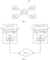
- FIG. 1 is a schematic diagram of a structure of a data processing system 100 according to an embodiment of this application.
- the system 100 includes devices 11 to 14 and a network 15. Different devices communicate with each other through the network 15.
- the network 15 implements communication based on protocols that support the remote direct memory access (RDMA), for example, InfiniBand (IB), RDMA over Converged Ethernet (RoCE), and internet Wide Area RDMA Protocol (iWARP).
- RDMA remote direct memory access
- IB InfiniBand
- RoCE RDMA over Converged Ethernet
- iWARP internet Wide Area RDMA Protocol
- one or more switches and/or routers may be used to implement communication between a plurality of nodes.
- IB InfiniBand
- RoCE RDMA over Converged Ethernet
- iWARP internet Wide Area RDMA Protocol
- switches and/or routers may be used to implement communication between a plurality of nodes.
- a device that sends a to-be-processed RDMA request may be referred to as a source device, and a device that receives a to-be-processed RDMA request may be referred to as a destination device.
- the devices 11 to 14 may be computing devices (for example, servers), storage devices (for example, storage arrays), or other devices that support the RDMA technology. It should be understood that a quantity of devices in the system 100 does not constitute a limitation on this application. In FIG. 1 , only an example in which the system includes four devices is used for description.
- the following further explains a manner of communication based on the RDMA technology between a source device and a destination device.
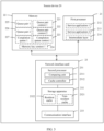
- FIG. 2 is a schematic diagram of a structure of another data processing system according to an embodiment of this application.
- an example including a source device 20 and a destination device 30 that apply an RDMA technology for data transmission is used for description.
- the source device 20 or the destination device 30 may be any device in FIG. 1 .
- the first processor 21 may be a central processing unit (CPU).
- the first processor 21 may be another general-purpose processor, a digital signal processor (DSP), an application-specific integrated circuit (ASIC), a field-programmable gate array (FPGA) or another programmable logic device, a discrete gate or transistor logic device, a discrete hardware component, or the like.
- DSP digital signal processor
- ASIC application-specific integrated circuit
- FPGA field-programmable gate array
- programmable logic device a discrete gate or transistor logic device, a discrete hardware component, or the like.
- the network interface card 23 may alternatively be referred to as a host channel adapter (HCA), and the network interface card 23 is an intelligent network interface card that supports the RDMA technology. In the RDMA technology, a processor does not participate in data transmission.
- HCA host channel adapter
- the source device 20 may directly send, by using the network interface card, data stored in the memory to the destination device 30 through the network 15, and a network interface card on the destination device 30 receives the data and stores the data in a memory.
- hardware structures of the source device 20 and the destination device 30 may be the same, or may be different.
- an example in which the hardware structures of the source device 20 and the destination device 30 are the same is used for description in the following embodiments.
- FIG. 3 is a schematic diagram of a structure of a source device 20 according to an embodiment of this application.
- the memory 22 can store a work request generated by a service application, data transmitted by a service application, and a data structure used in an RDMA transmission process.
- an interconnect context memory ICM
- ICM interconnect context memory
- the interconnect context memory may be a storage region in the memory.
- a queue pair QP
- the interconnect context memory is further configured to store a queue pair context (QPC) (for example, a queue pair context 1 and a queue pair context 2 shown in FIG. 1 ), a completion queue (CQ), a completion queue context (CQC), and a memory key context (MKC).
- QPC queue pair context
- CQ completion queue
- CQC completion queue context
- MKC memory key context
- a QP is also referred to as a network transmission queue pair.
- the first processor 21 of the source device allocates at least one queue pair to each service application.
- Each queue pair includes one send queue (SQ) and one receive queue (RQ).
- the SQ is used to store a work request sent by a service program to the destination device, and the RQ is used to store a work request that is sent by the destination device and that is received by a service program.
- Each SQ of a data transmit end is associated with an RQ of a data receive end.
- Each SQ or each RQ includes a plurality of entries. Each entry may also be referred to as a work queue entry (WQE).
- Each WQE is used to store an RDMA request generated by a service application, which is also referred to as a work request (WR).
- FIG. 4 is a schematic flowchart of QP-based communication between devices according to this embodiment.
- the source device 20 and the destination device 30 establish a communication connection at an initialization phase based on a QP1 and a QP11, so that a service program deployed on the source device communicates with the QP11 of the destination device based on the QP1 of the source device.
- the QP1 includes an SQ1 and an RQ1
- the QP11 includes an SQ11 and an RQ11.
- an RDMA send request generated by a service application running on the source device 20 may be stored in a WQE of the SQ1.
- a first processor of the destination device 30 generates an RDMA receive request and stores the RDMA receive request in a WQE of the RQ11. Similar to the SQ1 and the RQ11, when the RQ1 is associated with the SQ11, an RDMA receive request generated by a service application running on the source device 20 may be stored in the WQE of the SQ1.
- the first processor of the destination device 30 generates an RDMA send request and stores the RDMA send request in the WQE of the RQ11.
- a head pointer and a tail pointer may be used to indicate a WQE storage status in a queue.
- a head pointer of the SQ1 points to an address of a WQE2
- a tail pointer of the SQ1 points to an address of a WQE1.
- only the WQE2 in the SQ1 stores an RDMA request.
- the first processor 21 stores the request in a WQE3 of the SQ1.
- the head pointer of the SQ1 moves downwards by one storage unit to a corresponding storage location, namely, the WQE3.
- the network interface card fetches, from the SQ1, the RDMA request stored in the WQE2, the tail pointer of the SQ moves downwards by one storage unit to a corresponding storage location, namely, the WQE2.
- Each QP corresponds to one QPC, and the QPC is used to store configuration data of the QP.
- Table 1 is an example of a QPC data format. It should be noted that Table 1 is merely an example, and does not constitute a limitation on the QPC data format.
- the QPC data format may further include another field.
- Table 1 QPC data format Field Meaning QPN Indicates a number of a QP, where each QP corresponds to a unique number.
- QPN of a destination device Indicates a number of the other QP in a QP pair.
- SQ address Indicates an address of storage space for storing an SQ.
- SQ address index Indicates an Address of a storage unit to which a tail pointer of a storage SQ points.
- the network interface card may find, according to an SQ address in a QPC, an address of storage space of an SQ storing a to-be-processed RDMA request, and then find an address of the to-be-processed RDMA request based on an SQ address index.
- a CQ includes a plurality of completion queue elements (CQEs), and is used to store a notification returned to a service application after the network interface card completes execution of a work request or after the network interface card completes execution of a work request and receives a response from the destination device, where the notification includes a flag indicating whether a request is executed correctly and error code.
- CQEs completion queue elements
- each CQ corresponds to a CQC and stores a CQ-related attribute.
- the first processor 21 allocates a storage region in the memory to a service application of the source device, which is used to store to-be-sent and to-be-received data in work requests sent by the service application.
- the storage region is referred to as a memory region (MR).
- the memory region may store authentication identifiers of the source device and the destination device, for example, a local key (L_KEY) and a remote key (R_KEY).
- L_KEY local key
- R_KEY remote key
- the local key is used to store access permission for a memory region of the source device.
- the remote key is used to store access permission for a memory region of the destination device.
- FIG. 5 is another schematic flowchart of QP-based communication between devices according to an embodiment of this application. As shown in FIG.
- Each MR corresponds to an MKC that is used to store an authentication identifier of the MR and an address conversion relationship and that includes a local key, a remote key, and a mapping table for mapping a logical address (LBA) to a physical address (PBA).
- LBA logical address
- PBA physical address
- the memory 22 may include a read-only memory and a random access memory, and provides instructions and data to the first processor 21.
- the memory 22 may be a volatile memory or a non-volatile memory, or may include a volatile memory and a non-volatile memory.
- the non-volatile memory may be a read-only memory (ROM), a programmable read-only memory (PROM), an erasable programmable read-only memory (erasable PROM, EPROM), an electrically erasable programmable read-only memory (electrically EPROM, EEPROM), or a flash memory.
- the volatile memory may be a random access memory (RAM) and is used as an external cache.
- RAMs in a plurality of forms may be used, for example, a static random access memory (static RAM, SRAM), a dynamic random access memory (DRAM), a synchronous dynamic random access memory (synchronous DRAM, SDRAM), a double data rate synchronous dynamic random access memory (double data rate SDRAM, DDR SDRAM), an enhanced synchronous dynamic random access memory (enhanced SDRAM, ESDRAM), a synchlink dynamic random access memory (synchlink DRAM, SLDRAM), and a direct rambus random access memory (direct rambus RAM, DR RAM).
- static random access memory static random access memory
- DRAM dynamic random access memory
- SDRAM synchronous dynamic random access memory
- double data rate SDRAM double data rate SDRAM
- DDR SDRAM double data rate SDRAM
- ESDRAM enhanced synchronous dynamic random access memory
- synchlink dynamic random access memory synchlink dynamic random access memory
- SLDRAM direct rambus random access memory
- direct rambus RAM direct rambus RAM
- the network interface card 23 is a network interface card that supports an RDMA function, and supports a user-defined or standard RDMA protocol network port, for example, at least one of the IB protocol, the RoCE protocol, and the iWAPP protocol.
- one device may include at least one network interface card, and each network interface card can independently process a work request.
- the network interface card 23 includes a second processor 231, a storage apparatus 232, and a port 233.
- elements of the network interface card 23 that are not indispensable for understanding the present invention are omitted.
- the first processor 21 allocates an address range in memory space to the network interface card.
- the first processor 21 notifies the network interface card by changing an identifier corresponding to the QP in a doorbell register of the network interface card 23.
- a calculation unit 2311 of the network interface card obtains a QPC that is of the QP and that is indicated by the doorbell.
- An RDMA read request is used as an example.
- the calculation unit 2311 determines a location of the to-be-executed RDMA request in a send queue based on an SQ address and an SQ address index in the QPC, takes out the work request, and executes the work request.
- the computing unit 2311 After the work request is completed, the computing unit 2311 generates a CQE and stores the CQE in a CQ to notify a service application of a completion status of the request. Similar to the QP, the computing unit also needs to use a CQC corresponding to the CQ when generating the CQE.
- the computing unit 2311 when processing a work request of a service application, the computing unit 2311 needs to use a QPC, an MKC, and a CQC.
- the QPC, the MKC, and the CQC may be stored in the storage apparatus 232 of the network interface card.
- the storage apparatus of the network interface card cannot store all QPCs, MKCs, and CQCs used by service applications. Therefore, when the storage space of the storage apparatus of the network interface card is insufficient, a QPC, an MKC, and a CQC of an important service application may be preferentially stored.
- Resident cache space 2322 and non-resident cache space 2321 may be allocated in the space of the storage apparatus of the network interface card. When the space of the storage apparatus is insufficient, within a first time threshold, a QPC stored in the resident cache is not replaced, and a QPC stored in the non-resident cache is replaced.
- a storage control module 4312 may be used to manage the space of the storage apparatus, to complete QPC replacement.
- the QPC is used as an example.
- QPC storage types may be further classified into resident storage and non-resident storage based on QPC storage manners.
- a replacement method includes random replacement or a least recently used (LRU) replacement policy.
- a storage level may be further used to identify a storage type of a QPC.
- a QPC of each storage type may correspond to at least one storage level.
- QPCs at storage levels 4 and 5 are designated as resident QPCs.
- a replacement sequence of QPCs may be determined based on the storage levels.
- a QPC at a low storage level is preferentially replaced.
- An existing field in the RDMA transmission protocol for example, a service level SL field in the IB protocol, may be directly used to identify the QPC storage level.
- a new user-defined field in the RDMA transmission protocol may be alternatively used to identify the QPC storage level.
- network interface card 23 may be implemented as a hardware circuit or a software process run on a programmable processor, or may be implemented as a combination of elements implemented by hardware and software.
- an embodiment of this application provides a data processing method.
- an RDMA request of a service application at a specified service level is preferentially processed, and a QPC corresponding to the service application at the specified service level may be stored in the storage apparatus of the network interface card, which leads to improvement in a speed of transmitting a work request of a service application.
- FIG. 6 is a schematic flowchart of a data processing method according to an embodiment of this application. Specifically, the method includes the following steps.
- a network interface card of a source device obtains a service level of a service application.
- a work request generated by the service application is placed in a queue allocated by a first processor to the service application.
- the work request may be a to-be-processed RDMA write request, and is placed in an SQ allocated by the first processor.
- the first processor interacts with a doorbell module of the network interface card through a software/hardware interface, to notify the network interface card that a to-be-processed RDMA write request exists in the SQ.
- the first processor may also send a service level of a service application to the network interface card together.
- the service level of the service application may be determined based on a performance requirement of the service application, for example, a bandwidth requirement of the service application or latency sensitivity of the service application.
- the network interface card determines a processing sequence of the to-be-processed RDMA requests according to the service levels of the service applications. For example, a first SQ stores a first to-be-processed RDMA write request generated by a first service application, and a second SQ queue stores a second to-be-processed RDMA write request generated by a second service application, where it is specified that a service level of the first service application is higher than a service level of the second service application. In this case, the network interface card preferentially processes the first to-be-processed RDMA request in the first SQ.
- the network interface card first obtains, from a memory based on the service level of the service application and a QPN of the SQ in which the first to-be-processed RDMA request generated by the first service application is located, a QPC corresponding to the SQ. Based on storage manners of QPCs, the network interface card stores the QPCs in different types of storage space. Specifically, a QPC whose storage type is resident storage is stored in a resident cache, and a QPC whose storage type is non-resident storage is stored in a non-resident cache.
- the network interface card may obtain the QPC from the memory of the source device through direct memory access DMA.
- a network management device may be used to configure a network interface card on a device that performs data transmission, where the network management device may be an independent server connected to a same network as the source device, or may be the source device.
- the network management device may obtain communication capabilities of network interface cards of all devices in the network, and may configure space sizes of a resident cache and a non-resident cache on each network interface card based on the communication capabilities of the network interface cards and a requirement of a transmission task of a service application.
- the network interface card of the source device sends the work request to a network interface card of a destination device.
- the network interface card of the source device returns an execution result of the work request.
- the network interface card After the sending is complete, the network interface card records an execution result of an SQ in a CQ.
- the network interface card of the source device needs to generate an execution result after the network interface card of the destination device returns a receive response.
- the network interface card of the source device may immediately generate an execution result.
- a CQC is required when the network interface card puts the execution result in the CQ.
- a manner of obtaining and storing the CQC by the network interface card may be similar to the manner of processing the QPC.
- a work request of a service application at a specified service level may be preferentially transmitted based on a service level of the service application, and a QPC can be stored in a storage apparatus of a network interface card in a determined storage manner based on the service level of the service application and a transmission characteristic of a QP, so that the network interface card can preferentially ensure transmission efficiency of an RDMA request of a service application at a specified service level.
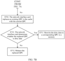
- FIG. 7A and FIG. 7B are a schematic flowchart of a QPC caching method according to an embodiment of this application. Specifically, the method includes the following steps.
- a network interface card determines whether a QPC needs to be cached. If yes, S702 is performed. If no, a current QPC does not need to be cached.
- the network interface card determines whether the QPC needs to be stored in a resident cache.
- the network interface card When there is no remaining storage space, the network interface card performs S704.
- the network interface card determines whether the replaced QPC is dirty data.
- the network interface card performs S711 to rewrite the dirty data to a corresponding QPC in a memory.
- the network interface card can preferentially ensure a storage manner of a QPC at a specified service level.
- the first storage region may be expanded by adding a new storage region, so that it is ensured that all QPCs of a service application at a specified service level can be stored in a determined storage manner. In this way, a transmission latency of a to-be-processed RDMA request of the service application at the service level can be controlled.
- FIG. 8A and FIG. 8B is a schematic flowchart of another QPC caching method provided in this application.
- a network interface card only needs to determine a storage type of a QPC to determine whether to store a QPC in a storage apparatus for a long time, and does not specify a designated storage region.
- the method specifically includes the following steps.
- the network interface card determines whether a QPC needs to be cached. If yes, S802 is performed. If no, the current QPC does not need to be cached, and S604 is directly performed.
- the network interface card determines whether the storage apparatus has remaining cache space.
- a cache controller When there is remaining cache space, a cache controller performs S804 to directly store the QPC in the remaining cache space.
- S805 is performed to determine whether a storage type of the current QPC is resident storage and whether a quantity of entries of existing QPCs whose storage types are resident storage in the cache is greater than or equal to a third threshold.
- the network interface card performs S806 to set the storage type of the current QPC to non-resident storage, and then performs S803.
- the cache controller directly performs S803.
- the network interface card replaces an existing QPC with the current QPC, where a replacement policy may be any one of the following policies.
- the network interface card determines whether the replaced QPC is dirty data.
- the network interface card performs S808 to rewrite the dirty data to a corresponding QPC in a memory.
- the cache controller performs S809 to release the replaced QPC.
- a queue context associated with a service application at a specified service level may be directly stored in another storage region other than the first storage region, for example, the second storage region. It is ensured that storage duration of the queue context is the same as storage duration of data in the first storage region, to ensure that the queue context corresponding to the service application at the specified service level can be stored in the storage apparatus of the network interface card for a long time. A long processing latency caused by frequent access by the network interface card to a memory of a device can be avoided, and a processing latency of a to-be-processed RDMA request corresponding to a service application at a specified service level can be reduced.
- a service application 1 and a service application 2 simultaneously run on a first processor 22 of a source device 20, where a service level of the service application 1 is higher than a service level of the service application 2.
- the source device 20 reads data from a destination device. Specific steps are as follows.
- Step 1 A service program 1 generates an RDMA read request 1 and stores the RDMA read request 1 in an SQ1, and the service program 2 generates an RDMA read request 2 and stores the RDMA read request 2 in an SQ2.
- Step 3a A second processor on the network interface card of the source device determines, according to service levels of the service applications, to first execute the work request in the SQ1, and retrieves a QPC1 of the SQ1 in a storage apparatus. After the retrieval fails, the second processor obtains the QPC1 from the memory.
- Step 4a The second processor marks a storage type of the QPC1 as resident storage according to the service level of the service application 1, and stores the QPC1 in a resident cache.
- Step 5a The second processor obtains the RDMA read request 1 of the service application 1 according to a QP address and a QP address index in the QPC1.
- Step 6 The second processor sends the service level of the service application 1 and the RDMA read request 1 to a communication interface.
- Step 7 The communication interface sends the service level of the service application 1 and the RDMA read request 1 to a network interface card 33 of the destination device 30.
- Step 8 The network interface card 33 of the destination device reads data from a memory according to the RDMA read request 1.
- Step 9 The network interface card 33 of the destination device returns data obtained through reading to the communication interface.
- Step 10 The communication interface sends the data obtained through reading to the second processor.
- Step 11 The second processor retrieves a CQC of a CQ in a storage apparatus. After the retrieval succeeds, the second processor obtains the CQC from the storage apparatus.
- the source device completes processing of the RDMA write request 1 of the service application 1, and then the network interface card of the source device processes the RDMA write request 2 of the service application 2.
- Step 3b The network interface card of the source device retrieves a QPC2 of the SQ2 in the storage apparatus. After the retrieval fails, the second processor obtains the QPC2 from the memory.
- Step 4b The second processor marks a storage type of the QPC2 as non-resident storage according to the service level of the service application 2, and stores the QPC2 in a non-resident cache.
- Step 5b The second processor obtains the RDMA read request 2 of the service application 2 according to an SQ address and an SQ address index in the QPC2.
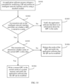
- FIG. 10 is a schematic flowchart of a method for modifying a QPC by using application software according to this embodiment. Specifically, the method includes the following steps.
- An application software process releases a command for modifying a QP and notifies an intelligent network interface card by using a doorbell module.
- An execution unit on the intelligent network interface card finds out whether a QPC is stored in a cache. If yes, the execution unit performs step S1003; otherwise, the execution unit performs step 1005 to notify the application software that there is no information about the QPC in the cache and the QP can be modified.
- the execution unit determines whether cache of the current QPC is dirty data. If yes, the execution unit executes step 1004 to write a newest QPC in the current cache to a system memory, and notifies the application software that the QP can be modified. If no, the execution unit executes step S1006 to release cache of the QPC, and notifies the application software that the QP can be modified.
- FIG. 11 is a schematic flowchart of a method for deleting a QPC by using application software according to this embodiment. Specifically, the method includes the following steps.
- An application software process releases a command for deleting a QP and notifies a network interface card by using a doorbell module.
- An execution unit on the network interface card finds out whether a QPC is stored in a cache. If the QPC exists, the execution unit performs step S1103, that is, releases a cache of the QPC, subtracts one entry from cache entries of a corresponding priority, and notifies the application software that the QP can be deleted. Otherwise, the execution unit performs step 114 to notify the application software that information about the QPC does not exist in the cache and the QP can be deleted.
- the data processing method provided in embodiments of this application may provide a flexible interface for application software, so that a user can manage a network connection through a network management plane to create, delete, query, and modify a QP, and perform Qos configuration based on an actual communication requirement.
- FIG. 12 is a schematic diagram of a data transmission apparatus 1200 according to this application.
- the apparatus includes an obtaining unit 1201, a processing unit 1202, and a communication unit 1203.
- the obtaining unit 1201 is configured to obtain a first notification message and a second notification message, where the first notification message indicates that a first to-be-processed remote direct memory access RDMA request exists in a first queue of a source device, the first queue is used to store a RDMA request of a first service application in the source device, the second notification message indicates that a second to-be-processed remote direct memory access RDMA request exists in a second queue of the source device, and the second queue is used to store an RDMA request of a second service application in the source device.
- the processing unit 1202 is configured to determine a processing sequence of the first queue and the second queue according to a service level of the first service application and a service level of the second service application.
- the communication unit 1203 is configured to send the first to-be-processed RDMA request and the second to-be-processed RDMA request to a destination device according to the processing sequence.
- the data transmission apparatus 1200 in this embodiment of this application may be implemented by a general-purpose processor (CPU) or an application-specific integrated circuit (ASIC), or may be implemented by a programmable logic device (PLD).
- the PLD may be a complex programmable logic device (CPLD), a field-programmable gate array (FPGA), generic array logic (GAL), or any combination thereof.
- CPLD complex programmable logic device
- FPGA field-programmable gate array
- GAL generic array logic
- the data transmission apparatus 1200 and modules thereof may be software modules.
- the processing unit 1202 may be further configured to: when processing of the first service application is arranged before processing of the second service application, obtain the first to-be-processed RDMA request, and send the first to-be-processed RDMA request to the destination device by using the communication unit 1203. Then the processing unit obtains the second to-be-processed request, and sends the second to-be-processed RDMA request to the destination device by using the communication unit 1203.
- the apparatus 1200 further includes a storage unit 1204.
- the processing unit 1202 is further configured to determine, according to a specified rule, a storage manner in which a context of the first queue is stored in the storage apparatus.
- the context of the first queue indicates an identifier of the destination device and an identifier of a queue associated with the first queue in the destination device.
- the processing unit 1202 stores the context of the first queue in the storage unit 1204 of the network interface card in accordance with the storage manner.
- the processing unit 1202 is further configured to determine, based on an operation type of the to-be-processed RDMA request in the first queue, the storage manner in which the context of the first queue is stored in the storage apparatus, where the operation type includes a persistent collective operation.
- the processing unit 1202 is further configured to: compare a size of a data packet in the to-be-processed RDMA request in the first queue with a first threshold; and determine, based on a comparison result, the storage manner in which the context of the first queue is stored in the storage apparatus.
- the processing unit 1202 is further configured to: compare a usage frequency of the first queue with a second threshold, where the first queue includes a plurality of work queue elements WQEs, each WQE is used to store one to-be-processed RDMA request, and the usage frequency is used to identify a quantity of to-be-processed RDMA requests stored within a first time threshold in the elements of the first queue.
- the processing unit 1202 is further configured to determine, based on the service level of the first service application, the storage manner in which the context of the first queue is stored in the storage apparatus.
- the first queue and the context of the first queue are stored in the memory of the source device. That after the obtaining unit 1201 obtains the context of the first queue from the memory, the processing unit 1202 is further configured to store the context of the first queue in the storage unit 1204 in accordance with the storage manner includes: The processing unit 1202 stores the context of the first queue in a first region of the storage unit 1204, and retain the context of the first queue in the first storage region within the first time threshold.
- the second queue and a context of the second queue are stored in the memory of the source device. That after the obtaining unit 1201 obtains the context of the second queue from the memory, the processing unit 1202 is further configured to store the context of the second queue in the storage unit 1204 in accordance with the storage manner includes: The processing unit 1202 stores the context of the second queue in a second storage region of the storage unit 1204, and deletes the context of the second queue from the second storage region after sending of the second to-be-processed RDMA request is completed.
- processing unit 1202 is further configured to obtain the context of the first queue or the context of the second queue from the memory of the source device through direct memory access DMA.
- the processing unit 1202 is further configured to use a storage region of a size of a third threshold in the second storage region as an added storage region of the first storage region.
- the processing unit 1202 is further configured to store a context of a third queue in the second storage region, where the context of the third queue is retained in the second storage region within the first time threshold, the context of the third queue indicates the identifier of the destination device and an identifier of a queue associated with the third queue in the destination device, and the third queue is used to store a to-be-processed RDMA request of a third service application.
- the processing unit 1202 is further configured to: store the context of the second queue in the second storage region of the storage apparatus of the network interface card, and delete a context of a fourth queue from the second storage region, where the context of the fourth queue indicates the identifier of the destination device and an identifier of a queue associated with the fourth queue in the destination device, and the fourth queue is used to store a to-be-processed RDMA request of a fourth service application.
- the processing unit 1202 is further configured to: store the context of the second queue in the second storage region of the storage apparatus of the network interface card, and delete a context of a fifth queue from the second storage region, where the context of the fifth queue indicates the identifier of the destination device and an identifier of a queue associated with the fifth queue in the destination device, the fifth queue is used to store a to-be-processed RDMA request of a fifth service application, and a storage level of the context of the fifth queue is lower than that of the context of the second queue.
- the processing unit 1202 stores the context of the second queue in the second storage region of the storage apparatus of the network interface card, and deletes a context of a sixth queue from the second storage region, where the context of the sixth queue indicates the identifier of the destination device and an identifier of a queue associated with the sixth queue in the destination device, the sixth queue is used to store a to-be-processed RDMA request of a sixth service application, and a storage level of the context of the sixth queue is the lowest among storage levels of contexts of all queues in the second storage region.
- the processing unit 1202 is further configured to determine whether a deleted context is dirty data. If yes, the processing unit 1202 stores the deleted context in a context cache region of a corresponding queue in the memory. If no, the processing unit 1202 directly deletes the deleted context. According to the foregoing method, the network interface card can instantly synchronize a queue context in the memory and a queue context in the storage apparatus.
- the obtaining unit 1201 is further configured to obtain the first to-be-processed RDMA request from the memory of the source device, and the processing unit 1202 stores the first to-be-processed RDMA request in the storage unit 1204. Then the communication unit 1203 is further configured to send the first to-be-processed RDMA request to the destination device.
- the obtaining unit 1202 obtains the second to-be-processed request, and sends the second to-be-processed RDMA request to the destination device by using the communication unit 1203 includes: The obtaining unit 1201 obtains the second to-be-processed RDMA request from the memory of the source device, the processing unit 1202 stores the second to-be-processed RDMA request in the storage unit 1204, and the communication unit 1203 sends the second to-be-processed RDMA request to the destination device.
- the data transmission apparatus 1200 in this embodiment of this application may correspondingly perform the method described in embodiments of this application.
- the foregoing and other operations and/or functions of the units in the data transmission apparatus 1200 are used to implement corresponding procedures of the methods in FIG. 6 to FIG. 11 .
- details are not described herein again.
- the apparatus 1200 may percept a service level of a service application, determine a processing sequence of a queue based on the service level corresponding to the service, and then perform data transmission of a to-be-processed RDMA request according to the processing sequence. In this way, it is ensured that a service application at a specified service level can be preferentially sent to a destination device, thereby reducing a latency in data transmission of the service application.
- FIG. 13 is a schematic diagram of a device 1300 according to an embodiment of this application.
- the device 1300 includes a first processor 1301, a first storage apparatus 1302, a network interface card 1303, a bus 1304, and a memory 1305. Communication between the first processor 1301, the first storage apparatus 1302, the network interface card 1303, and the memory 1305 is achieved by using the bus 1304, or in other manners such as wireless transmission.
- the first processor 1301 is configured to run a plurality of service applications, where each service application is associated with one queue.
- the memory is configured to store to-be-processed remote direct memory access RDMA requests in queues associated with the plurality of service applications and contexts of the queues associated with the plurality of service applications.
- the network interface card 1303 includes a second processor 1306, a second storage apparatus 1307, and a communication interface 1308.
- the second processor 1306 is configured to execute a computer-executable instruction stored in the second storage apparatus, to implement the following operation steps:
- the first processor 1301 or the second processor 1306 in this embodiment of this application may be a CPU, or may be another general-purpose processor, a digital signal processor (DSP), an application specific integrated circuit (ASIC), a field programmable gate array (FPGA) or another programmable logic device, a discrete gate or a transistor logic device, a discrete hardware component, or the like.
- the general-purpose processor may be a microprocessor, or may be any conventional processor or the like.
- the first storage apparatus 1302 or the second storage apparatus 1307 may include a read-only memory and a random access memory, and provides instructions and data to the processor 701.
- the first storage apparatus 1302 or the second storage apparatus 1307 may further include a non-volatile random access memory.
- the first storage apparatus 1302 or the second storage apparatus 1307 may further store device type information.
- the first storage apparatus 1302 or the second storage apparatus 1307 may be a volatile memory or a non-volatile memory, or may include a volatile memory and a non-volatile memory.
- the non-volatile memory may be a read-only memory (ROM), a programmable read-only memory (programmable ROM, PROM), an erasable programmable read-only memory (erasable PROM, EPROM), an electrically erasable programmable read-only memory (electrically EPROM, EEPROM), or a flash memory.
- the volatile memory may be a random access memory (RAM) and is used as an external cache.
- RAMs in a plurality of forms may be used, for example, a static random access memory (static RAM, SRAM), a dynamic random access memory (DRAM), a synchronous dynamic random access memory (synchronous DRAM, SDRAM), a double data rate synchronous dynamic random access memory (double data rate SDRAM, DDR SDRAM), an enhanced synchronous dynamic random access memory (enhanced SDRAM, ESDRAM), a synchlink dynamic random access memory (synchlink DRAM, SLDRAM), and a direct rambus random access memory (direct rambus RAM, DR RAM).
- static random access memory static random access memory
- DRAM dynamic random access memory
- SDRAM synchronous dynamic random access memory
- double data rate SDRAM double data rate SDRAM
- DDR SDRAM double data rate SDRAM
- ESDRAM enhanced synchronous dynamic random access memory
- synchlink dynamic random access memory synchlink dynamic random access memory
- SLDRAM direct rambus random access memory
- direct rambus RAM direct rambus RAM
- the bus 1304 may further include a power bus, a control bus, a status signal bus, and the like. However, for clarity of description, various buses are collectively marked as the bus 1304 in the figure.
- the device 1300 may correspond to the data transmission apparatus 1200 in the embodiment of this application, and may correspond to the source device in the methods shown in FIG. 6 to FIG. 11 in embodiments of this application.
- the device may be any device in the system shown in FIG. 1 .
- the foregoing and other operations and/or functions of the modules in the device 1300 are used to implement corresponding processes of the methods in the figures. For brevity, details are not described herein again.
- the device 1300 provided in this embodiment of this application can perceive service levels of service applications, determine a processing sequence of a plurality of queues based on service levels of different service applications, and perform data transmission of to-be-processed RDMA requests of different queues according to the processing sequence.
- the network interface card can perceive a service level of a service application, and send to-be-processed RDMA requests of service applications at different service levels based on the service levels.
- a to-be-processed RDMA request of a specified service application can be preferentially and quickly sent to the destination device, thereby reducing a processing latency of a service application at a specified service level.
- the chip includes a processor and a communication interface.
- the communication interface is configured to communicate with a processor of a device in which the chip is located.
- the processor may be an implementation form of the second processor 1306 in the network interface card 1302 shown in FIG. 13 .
- the processor of the chip is configured to implement functions of the steps of the methods performed by the network interface card of the source device in the methods shown in FIG. 6 to FIG. 11 . For brevity, details are not described herein again.
- the chip may be a chip that implements functions of the network interface card in FIG. 6 to FIG. 11 , or is the network interface card 1303 shown in FIG. 13 , or may be an offload card other than the network interface card 1303 in the device 1300 shown in FIG. 13 .
- the offload card is configured to determine a processing sequence of different queues based on service levels of service applications, and then send a to-be-processed RDMA request based on the determined processing sequence. For brevity, details are not described herein again.
- This application further provides a network interface card.
- a structure of the network interface card is the structure of the network interface card 1303 shown in FIG. 13 .
- the network interface card is configured to implement functions of the steps of the methods performed by the network interface card of the source device in the methods described in FIG. 6 to FIG. 11 . For brevity, details are not described herein again.
- All or some of the foregoing embodiments may be implemented by using software, hardware, firmware, or any combination thereof.
- software is used to implement the embodiments, all or some of the embodiments may be implemented in a form of a computer program product.
- the computer program product includes one or more computer instructions.
- the computer may be a general-purpose computer, a dedicated computer, a computer network, or another programmable apparatus.
- the computer instructions may be stored in a computer-readable storage medium or may be transmitted from a computer-readable storage medium to another computer-readable storage medium.
- the computer instructions may be transmitted from a website, computer, server, or data center to another website, computer, server, or data center in a wired manner (for example, a coaxial cable, an optical fiber, or a digital subscriber line (DSL)) or a wireless manner (for example, infrared, radio, and microwave).
- the computer-readable storage medium may be any usable medium accessible by a computer, or a data storage device, such as a server or a data center, integrating one or more usable media.
- the usable medium may be a magnetic medium (for example, a floppy disk, a hard disk drive, or a magnetic tape), an optical medium (for example, a DVD), a semiconductor medium, or the like.
- the semiconductor medium may be a solid state drive (SSD).
Landscapes
- Engineering & Computer Science (AREA)
- Theoretical Computer Science (AREA)
- Physics & Mathematics (AREA)
- General Engineering & Computer Science (AREA)
- General Physics & Mathematics (AREA)
- Signal Processing (AREA)
- Computer Networks & Wireless Communication (AREA)
- Human Computer Interaction (AREA)
- Computer Hardware Design (AREA)
- Software Systems (AREA)
- Mathematical Physics (AREA)
- Computer And Data Communications (AREA)
- Multi Processors (AREA)
Claims (15)
- Procédé de transmission de données, dans lequel le procédé comprend :l'obtention, par une carte d'interface réseau (23, 33, 1303) d'un dispositif source (20), d'un premier message de notification, dans lequel le premier message de notification indique qu'une première demande d'accès direct à la mémoire à distance (22, 1305), RDMA, à traiter existe dans une première file d'attente du dispositif source (20), et la première file d'attente est utilisée pour stocker une demande d'une première application de service du dispositif source (20) ;l'obtention, par la carte d'interface réseau (23, 33, 1303), d'un second message de notification, dans lequel le second message de notification indique qu'une seconde demande RDMA à traiter existe dans une deuxième file d'attente du dispositif source (20), et la deuxième file d'attente est utilisée pour stocker une demande d'une deuxième application de service du dispositif source (20) ;la détermination, par la carte d'interface réseau (23, 33, 1303), d'une séquence de traitement de la première file d'attente et de la deuxième file d'attente en fonction d'un niveau de service de la première application de service et d'un niveau de service de la deuxième application de service ; etl'envoi, par la carte d'interface réseau (23, 33, 1303), de la première demande RDMA à traiter et de la seconde demande RDMA à traiter à un dispositif de destination (30) en fonction de la séquence de traitement.
- Procédé selon la revendication 1, dans lequel l'envoi de la première demande RDMA à traiter et de la seconde demande RDMA à traiter à un dispositif de destination (30) en fonction de la séquence de traitement comprend :lorsque le traitement de la première application de service est organisé avant le traitement de la deuxième application de service, l'obtention, par la carte d'interface réseau (23, 33, 1303), de la première demande RDMA à traiter, et l'envoi de la première demande RDMA à traiter au dispositif de destination (30) ; etaprès l'envoi de la première demande à traiter au dispositif de destination (30), l'obtention, par la carte d'interface réseau (23, 33, 1303), de la seconde demande à traiter, et l'envoi de la seconde demande à traiter au dispositif de destination (30).
- Procédé selon la revendication 2, dans lequel la carte d'interface réseau (23, 33, 1303) comprend un appareil de stockage (232), et avant que la carte d'interface réseau (23, 33, 1303) n'envoie la demande RDMA à traiter dans la première file d'attente au dispositif de destination (30), le procédé comprend également :la détermination, par la carte d'interface réseau (23, 33, 1303) selon une règle spécifiée, d'un mode de stockage selon lequel un contexte de la première file d'attente est stocké dans l'appareil de stockage (232), dans lequel le contexte de la première file d'attente indique un identifiant du dispositif de destination (30) et un identifiant d'une file d'attente associée à la première file d'attente dans le dispositif de destination (30) ;l'obtention, par la carte d'interface réseau (23, 33, 1303), du contexte de la première file d'attente ; etle stockage, par la carte d'interface réseau (23, 33, 1303), du contexte de la première file d'attente dans l'appareil de stockage (232) de la carte d'interface réseau (23, 33, 1303) selon le mode de stockage.
- Procédé selon la revendication 3, dans lequel la détermination, par la carte d'interface réseau (23, 33, 1303) selon une règle spécifiée, d'un mode de stockage selon lequel un contexte de la première file d'attente est stocké dans l'appareil de stockage (232) comprend :
la détermination, par la carte d'interface réseau (23, 33, 1303) sur la base d'un type d'opération de la demande RDMA à traiter dans la première file d'attente, du mode de stockage selon lequel le contexte de la première file d'attente est stocké dans l'appareil de stockage (232), dans lequel le type d'opération comprend une opération collective persistante. - Procédé selon la revendication 3, dans lequel la détermination, par la carte d'interface réseau (23, 33, 1303) selon une règle spécifiée, d'un mode de stockage selon lequel un contexte de la première file d'attente est stocké dans l'appareil de stockage (232) comprend :la comparaison, par la carte d'interface réseau (23, 33, 1303), d'une taille d'un paquet de données dans la demande RDMA à traiter dans la première file d'attente avec un premier seuil ; etla détermination, par la carte d'interface réseau (23, 33, 1303) sur la base d'un résultat de comparaison, du mode de stockage selon lequel le contexte de la première file d'attente est stocké dans l'appareil de stockage (232).
- Procédé selon la revendication 3, dans lequel la détermination, par la carte d'interface réseau (23, 33, 1303) selon une règle spécifiée, d'un mode de stockage selon lequel un contexte de la première file d'attente est stocké dans l'appareil de stockage (232) comprend :la comparaison, par la carte d'interface réseau (23, 33, 1303), d'une fréquence d'utilisation de la première file d'attente avec un deuxième seuil, dans lequel la première file d'attente comprend une pluralité d'éléments de file d'attente de travail WQE, chaque WQE est utilisé pour stocker une demande RDMA à traiter, et la fréquence d'utilisation est utilisée pour identifier une quantité de demandes RDMA à traiter stockées dans un premier seuil de temps dans les éléments de la première file d'attente ; etla détermination, par la carte d'interface réseau (23, 33, 1303) sur la base d'un résultat de comparaison, du mode de stockage selon lequel le contexte de la première file d'attente est stocké dans l'appareil de stockage (232).
- Procédé selon la revendication 3, dans lequel la détermination, par la carte d'interface réseau (23, 33, 1303) selon une règle spécifiée, d'un mode de stockage selon lequel un contexte de la première file d'attente est stocké dans l'appareil de stockage (232) comprend :
la détermination, par la carte d'interface réseau (23, 33, 1303) sur la base du niveau de service de la première application de service, du mode de stockage selon lequel le contexte de la première file d'attente est stocké dans l'appareil de stockage (232). - Procédé selon l'une quelconque des revendications 3 à 7, dans lequel la première file d'attente et le contexte de la première file d'attente sont stockés dans une mémoire (22, 1305) du dispositif source (20), l'obtention, par la carte d'interface réseau (23, 33, 1303), du contexte de la première file d'attente comprend :l'obtention, par la carte d'interface réseau (23, 33, 1303), du contexte de la première file d'attente à partir de la mémoire (22, 1305) du dispositif source (20) ; etle stockage, par la carte d'interface réseau (23, 33, 1303), du contexte de la première file d'attente dans l'appareil de stockage (232) de la carte d'interface réseau (23, 33, 1303) selon le mode de stockage comprend :
le stockage, par la carte d'interface réseau (23, 33, 1303), du contexte de la première file d'attente dans une première région de stockage de l'appareil de stockage (232) de la carte d'interface réseau (23, 33, 1303), et la conservation du contexte de la première file d'attente dans la première région de stockage dans le premier seuil de temps. - Procédé selon la revendication 2, dans lequel la deuxième file d'attente et un contexte de la deuxième file d'attente sont stockés dans la mémoire (22, 1305) du dispositif source (20), et avant que la carte d'interface réseau (23, 33, 1303) n'obtienne la seconde demande RDMA à traiter, le procédé comprend également :l'obtention, par la carte d'interface réseau (23, 33, 1303), du contexte de la deuxième file d'attente à partir de la mémoire (22, 1305) du dispositif source (20) ; etle stockage, par la carte d'interface réseau (23, 33, 1303), du contexte de la deuxième file d'attente dans une seconde région de stockage de l'appareil de stockage (232) de la carte d'interface réseau (23, 33, 1303), et la suppression du contexte de la deuxième file d'attente de la seconde région de stockage une fois l'envoi de la seconde demande RDMA à traiter terminé.
- Procédé selon la revendication 8 ou 9, l'obtention, par la carte d'interface réseau (23, 33, 1303), du contexte de la première file d'attente à partir de la mémoire (22, 1305) du dispositif source (20) comprend :
l'obtention, par la carte d'interface réseau (23, 33, 1303), du contexte de la première file d'attente ou du contexte de la deuxième file d'attente à partir de la mémoire (22, 1305) du dispositif source (20) par accès direct à la mémoire (22, 1305) DMA. - Procédé selon la revendication 8 ou 9, dans lequel le procédé comprend également :
lorsque l'espace restant de la première région de stockage est inférieur à un troisième seuil, l'utilisation, par la carte d'interface réseau (23, 33, 1303), d'une région de stockage d'une taille d'un quatrième seuil dans la seconde région de stockage comme région de stockage ajoutée de la première région de stockage. - Procédé selon la revendication 8 ou 9, dans lequel le procédé comprend également :
lorsque l'espace restant de la première région de stockage est inférieur à un troisième seuil, le stockage, par la carte d'interface réseau (23, 33, 1303), d'un contexte d'une troisième file d'attente dans la seconde région de stockage, dans lequel le contexte de la troisième file d'attente est conservé dans la seconde région de stockage dans le premier seuil de temps, le contexte de la troisième file d'attente indique l'identifiant du dispositif de destination (30) et un identifiant d'une file d'attente associée à la troisième file d'attente dans le dispositif de destination (30), et la troisième file d'attente est utilisée pour stocker une demande RDMA à traiter d'une troisième application de service. - Procédé selon la revendication 3, dans lequel la carte d'interface réseau (23, 33, 1303) obtient la première demande RDMA à traiter ou la seconde demande RDMA à traiter à partir de la mémoire (22, 1305) du dispositif source (20) par accès direct à la mémoire (22, 1305) DMA.
- Puce de carte d'interface réseau (23, 33, 1303), dans laquelle la puce de carte d'interface réseau (23, 33, 1303) comprend un processeur (231, 701, 1306) et une interface de communication (1308), l'interface de communication (1308) est configurée pour communiquer avec un processeur (231, 701, 1306) d'un dispositif (11-14, 20, 1300) dans lequel se trouve la puce de carte d'interface réseau (23, 33, 1303), et le processeur (231, 701, 1306) de la puce de carte d'interface réseau (23, 33, 1303) est configuré pour mettre en œuvre toutes les étapes du procédé selon l'une quelconque des revendications 1 à 13.
- Dispositif (11-14, 20, 1300), dans lequel le dispositif (11-14, 20, 1300) comprend un premier processeur (21, 1301), une mémoire (22, 1305) et une carte d'interface réseau (23, 33, 1303), le premier processeur (21, 1301) est configuré pour exécuter une pluralité d'applications de service (1, 2), chaque application de service (1, 2) est associée à une file d'attente, la mémoire (22, 1305) est configurée pour stocker des demandes d'accès direct à la mémoire à distance, RDMA, (22, 1305) à traiter dans des files d'attente associées à la pluralité d'applications de service (1, 2), et la carte d'interface réseau (23, 33, 1303) est configurée pour mettre en œuvre toutes les étapes de procédé selon l'une quelconque des revendications 1 à 13.
Applications Claiming Priority (3)
| Application Number | Priority Date | Filing Date | Title |
|---|---|---|---|
| CN202010639909 | 2020-07-06 | ||
| CN202110080370.0A CN113900972B (zh) | 2020-07-06 | 2021-01-21 | 一种数据传输的方法、芯片和设备 |
| PCT/CN2021/088771 WO2022007470A1 (fr) | 2020-07-06 | 2021-04-21 | Procédé de transmission de données, puce et dispositif |
Publications (3)
| Publication Number | Publication Date |
|---|---|
| EP4160425A1 EP4160425A1 (fr) | 2023-04-05 |
| EP4160425A4 EP4160425A4 (fr) | 2023-11-01 |
| EP4160425B1 true EP4160425B1 (fr) | 2025-03-26 |
Family
ID=79187408
Family Applications (1)
| Application Number | Title | Priority Date | Filing Date |
|---|---|---|---|
| EP21837789.3A Active EP4160425B1 (fr) | 2020-07-06 | 2021-04-21 | Procédé de transmission de données, puce et dispositif |
Country Status (4)
| Country | Link |
|---|---|
| US (1) | US12487963B2 (fr) |
| EP (1) | EP4160425B1 (fr) |
| CN (1) | CN113900972B (fr) |
| WO (1) | WO2022007470A1 (fr) |
Cited By (1)
| Publication number | Priority date | Publication date | Assignee | Title |
|---|---|---|---|---|
| US12487963B2 (en) * | 2020-07-06 | 2025-12-02 | Huawei Technologies Co., Ltd. | Data transmission method, chip, and device |
Families Citing this family (12)
| Publication number | Priority date | Publication date | Assignee | Title |
|---|---|---|---|---|
| CN114584492B (zh) * | 2022-02-15 | 2023-01-24 | 珠海星云智联科技有限公司 | 一种延时测量方法、系统以及相关设备 |
| CN114979022B (zh) * | 2022-05-20 | 2023-07-28 | 北京百度网讯科技有限公司 | 远程直接数据存取的实现方法、装置、适配器和存储介质 |
| CN115086207B (zh) * | 2022-06-14 | 2024-08-20 | 深信服科技股份有限公司 | 一种网卡检测方法、装置及电子设备和存储介质 |
| CN115174484B (zh) * | 2022-06-16 | 2024-11-08 | 阿里巴巴(中国)有限公司 | 基于rdma的数据传输方法、装置、设备及存储介质 |
| US12131029B2 (en) | 2022-10-28 | 2024-10-29 | Hewlett Packard Enterprise Development Lp | Datatype engine to support high performance computing |
| CN118264353A (zh) * | 2022-12-27 | 2024-06-28 | 华为技术有限公司 | 一种存储设备、数据通信方法以及系统 |
| WO2025025678A1 (fr) * | 2023-08-01 | 2025-02-06 | 华为云计算技术有限公司 | Procédé d'accès à des données basé sur un service de stockage en nuage, carte de délestage, système et dispositif |
| CN117687795B (zh) * | 2024-01-25 | 2024-05-10 | 珠海星云智联科技有限公司 | 用于远程直接内存访问的硬件卸载方法、设备及介质 |
| CN117749739B (zh) | 2024-02-18 | 2024-06-04 | 北京火山引擎科技有限公司 | 数据发送方法、数据接收方法、装置、设备及存储介质 |
| CN120583460A (zh) * | 2024-03-01 | 2025-09-02 | 华为技术有限公司 | 一种报文传输方法及装置 |
| CN119544648B (zh) * | 2024-11-07 | 2025-10-24 | 中汽创智科技有限公司 | 一种报文通信处理方法、装置及电子设备 |
| CN119583488A (zh) * | 2024-12-06 | 2025-03-07 | 天翼云科技有限公司 | 网卡控制方法、装置、通信设备、可读存储介质和程序产品 |
Family Cites Families (43)
| Publication number | Priority date | Publication date | Assignee | Title |
|---|---|---|---|---|
| KR20000075358A (ko) * | 1999-05-27 | 2000-12-15 | 윤종용 | 이동통신시스템에서 라디오링크프로토콜에 따른 가변길이의 데이터 송수신 장치 및 방법 |
| US7245627B2 (en) * | 2002-04-23 | 2007-07-17 | Mellanox Technologies Ltd. | Sharing a network interface card among multiple hosts |
| US7076569B1 (en) * | 2002-10-18 | 2006-07-11 | Advanced Micro Devices, Inc. | Embedded channel adapter having transport layer configured for prioritizing selection of work descriptors based on respective virtual lane priorities |
| US20050122904A1 (en) * | 2003-12-04 | 2005-06-09 | Kumar Anil K. | Preventative congestion control for application support |
| US7653754B2 (en) * | 2004-01-05 | 2010-01-26 | Mellanox Technologies Ltd. | Method, system and protocol that enable unrestricted user-level access to a network interface adapter |
| US7945705B1 (en) * | 2004-05-25 | 2011-05-17 | Chelsio Communications, Inc. | Method for using a protocol language to avoid separate channels for control messages involving encapsulated payload data messages |
| US7826470B1 (en) * | 2004-10-19 | 2010-11-02 | Broadcom Corp. | Network interface device with flow-oriented bus interface |
| US7996583B2 (en) * | 2006-08-31 | 2011-08-09 | Cisco Technology, Inc. | Multiple context single logic virtual host channel adapter supporting multiple transport protocols |
| US8014282B2 (en) * | 2008-06-26 | 2011-09-06 | Intel Corporation | Hashing packet contents to determine a processor |
| US7852763B2 (en) * | 2009-05-08 | 2010-12-14 | Bae Systems Information And Electronic Systems Integration Inc. | System and method for determining a transmission order for packets at a node in a wireless communication network |
| US9871734B2 (en) * | 2012-05-28 | 2018-01-16 | Mellanox Technologies, Ltd. | Prioritized handling of incoming packets by a network interface controller |
| US9047195B2 (en) * | 2012-07-05 | 2015-06-02 | Hitachi, Ltd. | Computer system with virtualization mechanism and management table, cache control method and computer program |
| US9268623B2 (en) * | 2012-12-18 | 2016-02-23 | International Business Machines Corporation | Analyzing update conditions for shared variable directory information in a parallel computer |
| US9037792B1 (en) * | 2013-06-06 | 2015-05-19 | Symantec Corporation | Systems and methods for providing caching for applications with solid-state storage devices |
| US9986028B2 (en) * | 2013-07-08 | 2018-05-29 | Intel Corporation | Techniques to replicate data between storage servers |
| US8949486B1 (en) * | 2013-07-17 | 2015-02-03 | Mellanox Technologies Ltd. | Direct memory access to storage devices |
| US10394751B2 (en) * | 2013-11-06 | 2019-08-27 | Solarflare Communications, Inc. | Programmed input/output mode |
| CN103647807B (zh) * | 2013-11-27 | 2017-12-15 | 华为技术有限公司 | 一种信息缓存方法、装置和通信设备 |
| US20160212214A1 (en) * | 2015-01-16 | 2016-07-21 | Avago Technologies General Ip (Singapore) Pte. Ltd. | Tunneled remote direct memory access (rdma) communication |
| US9886405B1 (en) * | 2015-03-30 | 2018-02-06 | Amazon Technologies, Inc. | Low latency write requests over a network using a pipelined I/O adapter device |
| US10152441B2 (en) * | 2015-05-18 | 2018-12-11 | Mellanox Technologies, Ltd. | Host bus access by add-on devices via a network interface controller |
| US10713210B2 (en) * | 2015-10-13 | 2020-07-14 | Microsoft Technology Licensing, Llc | Distributed self-directed lock-free RDMA-based B-tree key-value manager |
| KR101941416B1 (ko) * | 2015-12-29 | 2019-04-12 | 아마존 테크놀로지스, 인크. | 네트워킹 기술들 |
| US10148581B2 (en) * | 2016-05-30 | 2018-12-04 | Mellanox Technologies, Ltd. | End-to-end enhanced reliable datagram transport |
| US10944684B2 (en) * | 2017-05-23 | 2021-03-09 | Cable Television Laboratories, Inc. | Systems and methods for queue protection |
| EP3688596B1 (fr) * | 2017-09-27 | 2024-05-08 | INTEL Corporation | Produit programme d'ordinateur, système et procédé pour gérer l'accès à des ressources de stockage à partir de multiples applications |
| US10652108B2 (en) * | 2017-09-29 | 2020-05-12 | Intel Corporation | Techniques to establish service level agreements or quality of service for remotely accessible storage devices |
| CN110022269B (zh) * | 2018-01-09 | 2022-12-16 | 阿里巴巴集团控股有限公司 | 通信数据处理方法、装置和设备 |
| US10574755B2 (en) * | 2018-03-28 | 2020-02-25 | Wipro Limited | Method and high performance computing (HPC) switch for optimizing distribution of data packets |
| CN108989235B (zh) * | 2018-08-28 | 2022-11-01 | 新华三技术有限公司 | 一种报文转发控制方法及装置 |
| CN109491809A (zh) * | 2018-11-12 | 2019-03-19 | 西安微电子技术研究所 | 一种降低高速总线延迟的通信方法 |
| US10944660B2 (en) * | 2019-02-08 | 2021-03-09 | Intel Corporation | Managing congestion in a network |
| US11451455B2 (en) * | 2019-08-14 | 2022-09-20 | Intel Corporation | Technologies for latency based service level agreement management in remote direct memory access networks |
| US11991025B2 (en) * | 2019-12-04 | 2024-05-21 | Intel Corporation | Transceiver parameter determination |
| CN111225042B (zh) * | 2019-12-27 | 2021-09-17 | 腾讯科技(深圳)有限公司 | 数据传输的方法、装置、计算机设备以及存储介质 |
| US12218840B2 (en) * | 2020-06-16 | 2025-02-04 | Intel Corporation | Flexible scheme for adding rules to a NIC pipeline |
| US12046578B2 (en) * | 2020-06-26 | 2024-07-23 | Intel Corporation | Stacked die network interface controller circuitry |
| US11765250B2 (en) * | 2020-06-26 | 2023-09-19 | Western Digital Technologies, Inc. | Devices and methods for managing network traffic for a distributed cache |
| CN113900972B (zh) * | 2020-07-06 | 2026-02-13 | 华为技术有限公司 | 一种数据传输的方法、芯片和设备 |
| US11503140B2 (en) * | 2020-12-11 | 2022-11-15 | Western Digital Technologies, Inc. | Packet processing by programmable network interface |
| CN114647363B (zh) * | 2020-12-17 | 2025-06-24 | 伊姆西Ip控股有限责任公司 | 用于数据处理的方法、电子设备和计算机程序产品 |
| US20210359955A1 (en) * | 2021-07-23 | 2021-11-18 | Intel Corporation | Cache allocation system |
| US20250110814A1 (en) * | 2023-09-28 | 2025-04-03 | Apple Inc. | Signal aggregation |
-
2021
- 2021-01-21 CN CN202110080370.0A patent/CN113900972B/zh active Active
- 2021-04-21 EP EP21837789.3A patent/EP4160425B1/fr active Active
- 2021-04-21 WO PCT/CN2021/088771 patent/WO2022007470A1/fr not_active Ceased
-
2023
- 2023-01-05 US US18/150,647 patent/US12487963B2/en active Active
Cited By (1)
| Publication number | Priority date | Publication date | Assignee | Title |
|---|---|---|---|---|
| US12487963B2 (en) * | 2020-07-06 | 2025-12-02 | Huawei Technologies Co., Ltd. | Data transmission method, chip, and device |
Also Published As
| Publication number | Publication date |
|---|---|
| CN113900972A (zh) | 2022-01-07 |
| US20230153264A1 (en) | 2023-05-18 |
| EP4160425A4 (fr) | 2023-11-01 |
| EP4160425A1 (fr) | 2023-04-05 |
| WO2022007470A1 (fr) | 2022-01-13 |
| CN113900972B (zh) | 2026-02-13 |
| US12487963B2 (en) | 2025-12-02 |
Similar Documents
| Publication | Publication Date | Title |
|---|---|---|
| EP4160425B1 (fr) | Procédé de transmission de données, puce et dispositif | |
| US20260012417A1 (en) | Network interface for data transport in heterogeneous computing environments | |
| CN108701004B (zh) | 一种数据处理的系统、方法及对应装置 | |
| US11169938B2 (en) | Non-volatile memory (NVM) express (NVMe) data processing method and system | |
| EP3572948B1 (fr) | Procédé et dispositif de gestion de ressources | |
| EP3028162B1 (fr) | Accès direct à la mémoire persistante d'un stockage partagé | |
| US20200364080A1 (en) | Interrupt processing method and apparatus and server | |
| US11231964B2 (en) | Computing device shared resource lock allocation | |
| US12519745B2 (en) | Network node configuration method and apparatus, and access request processing method and apparatus | |
| CN116204487A (zh) | 远程数据访问方法及装置 | |
| WO2025118533A1 (fr) | Procédé de transmission de données et dispositif informatique | |
| EP4686169A1 (fr) | Procédé et dispositif de transmission de paquets | |
| EP3964996A1 (fr) | Procédé et dispositif d'accès à une base de données | |
| US10255213B1 (en) | Adapter device for large address spaces | |
| US20240256320A1 (en) | Systems and methods for peripheral device control virtualization | |
| US20240256319A1 (en) | Systems and methods for remote peripheral device control virtualization | |
| EP4357949A1 (fr) | Procédé et appareil d'authentification et système de stockage | |
| EP3800924A1 (fr) | Procédé et dispositif de gestion de données | |
| US12242409B2 (en) | Systems for methods of throttling in a network | |
| EP4683305A1 (fr) | Procédé et appareil de transmission de message | |
| WO2024113090A1 (fr) | Procédé, appareil et système d'accès mémoire | |
| WO2025190259A1 (fr) | Procédé de gestion de ressources et dispositif associé | |
| CN108664417A (zh) | 一种目录更新方法及装置 | |
| WO2025148360A1 (fr) | Procédé de communication, dispositif informatique et système informatique | |
| CN115396373A (zh) | 基于云服务器的信息处理方法、系统及电子设备 |
Legal Events
| Date | Code | Title | Description |
|---|---|---|---|
| STAA | Information on the status of an ep patent application or granted ep patent |
Free format text: STATUS: THE INTERNATIONAL PUBLICATION HAS BEEN MADE |
|
| PUAI | Public reference made under article 153(3) epc to a published international application that has entered the european phase |
Free format text: ORIGINAL CODE: 0009012 |
|
| STAA | Information on the status of an ep patent application or granted ep patent |
Free format text: STATUS: REQUEST FOR EXAMINATION WAS MADE |
|
| 17P | Request for examination filed |
Effective date: 20230102 |
|
| AK | Designated contracting states |
Kind code of ref document: A1 Designated state(s): AL AT BE BG CH CY CZ DE DK EE ES FI FR GB GR HR HU IE IS IT LI LT LU LV MC MK MT NL NO PL PT RO RS SE SI SK SM TR |
|
| DAV | Request for validation of the european patent (deleted) | ||
| DAX | Request for extension of the european patent (deleted) | ||
| A4 | Supplementary search report drawn up and despatched |
Effective date: 20231004 |
|
| RIC1 | Information provided on ipc code assigned before grant |
Ipc: G06F 12/0846 20160101ALI20230927BHEP Ipc: H04L 49/90 20220101ALI20230927BHEP Ipc: G06F 12/126 20160101ALI20230927BHEP Ipc: G06F 13/12 20060101ALI20230927BHEP Ipc: G06F 13/28 20060101ALI20230927BHEP Ipc: G06F 3/06 20060101ALI20230927BHEP Ipc: H04L 67/568 20220101ALI20230927BHEP Ipc: G06F 13/18 20060101ALI20230927BHEP Ipc: H04L 47/10 20220101ALI20230927BHEP Ipc: H04L 47/2475 20220101ALI20230927BHEP Ipc: H04L 47/6295 20220101ALI20230927BHEP Ipc: H04L 47/62 20220101ALI20230927BHEP Ipc: G06F 13/16 20060101AFI20230927BHEP |
|
| GRAP | Despatch of communication of intention to grant a patent |
Free format text: ORIGINAL CODE: EPIDOSNIGR1 |
|
| STAA | Information on the status of an ep patent application or granted ep patent |
Free format text: STATUS: GRANT OF PATENT IS INTENDED |
|
| RIC1 | Information provided on ipc code assigned before grant |
Ipc: H04L 67/1097 20220101ALI20241111BHEP Ipc: H04L 47/24 20220101ALI20241111BHEP Ipc: H04L 49/90 20220101ALI20241111BHEP Ipc: G06F 12/0846 20160101ALI20241111BHEP Ipc: H04L 47/62 20220101ALI20241111BHEP Ipc: H04L 47/6295 20220101ALI20241111BHEP Ipc: H04L 47/2475 20220101ALI20241111BHEP Ipc: H04L 47/10 20220101ALI20241111BHEP Ipc: G06F 13/18 20060101ALI20241111BHEP Ipc: H04L 67/568 20220101ALI20241111BHEP Ipc: G06F 3/06 20060101ALI20241111BHEP Ipc: G06F 13/28 20060101ALI20241111BHEP Ipc: G06F 13/12 20060101ALI20241111BHEP Ipc: G06F 12/126 20160101ALI20241111BHEP Ipc: G06F 13/16 20060101AFI20241111BHEP |
|
| INTG | Intention to grant announced |
Effective date: 20241121 |
|
| GRAS | Grant fee paid |
Free format text: ORIGINAL CODE: EPIDOSNIGR3 |
|
| GRAA | (expected) grant |
Free format text: ORIGINAL CODE: 0009210 |
|
| STAA | Information on the status of an ep patent application or granted ep patent |
Free format text: STATUS: THE PATENT HAS BEEN GRANTED |
|
| AK | Designated contracting states |
Kind code of ref document: B1 Designated state(s): AL AT BE BG CH CY CZ DE DK EE ES FI FR GB GR HR HU IE IS IT LI LT LU LV MC MK MT NL NO PL PT RO RS SE SI SK SM TR |
|
| REG | Reference to a national code |
Ref country code: GB Ref legal event code: FG4D |
|
| REG | Reference to a national code |
Ref country code: CH Ref legal event code: EP |
|
| REG | Reference to a national code |
Ref country code: DE Ref legal event code: R096 Ref document number: 602021028259 Country of ref document: DE |
|
| REG | Reference to a national code |
Ref country code: IE Ref legal event code: FG4D |
|
| REG | Reference to a national code |
Ref country code: NL Ref legal event code: FP |
|
| PG25 | Lapsed in a contracting state [announced via postgrant information from national office to epo] |
Ref country code: RS Free format text: LAPSE BECAUSE OF FAILURE TO SUBMIT A TRANSLATION OF THE DESCRIPTION OR TO PAY THE FEE WITHIN THE PRESCRIBED TIME-LIMIT Effective date: 20250626 |
|
| PG25 | Lapsed in a contracting state [announced via postgrant information from national office to epo] |
Ref country code: FI Free format text: LAPSE BECAUSE OF FAILURE TO SUBMIT A TRANSLATION OF THE DESCRIPTION OR TO PAY THE FEE WITHIN THE PRESCRIBED TIME-LIMIT Effective date: 20250326 |
|
| PGFP | Annual fee paid to national office [announced via postgrant information from national office to epo] |
Ref country code: DE Payment date: 20250408 Year of fee payment: 5 |
|
| REG | Reference to a national code |
Ref country code: LT Ref legal event code: MG9D |
|
| PG25 | Lapsed in a contracting state [announced via postgrant information from national office to epo] |
Ref country code: NO Free format text: LAPSE BECAUSE OF FAILURE TO SUBMIT A TRANSLATION OF THE DESCRIPTION OR TO PAY THE FEE WITHIN THE PRESCRIBED TIME-LIMIT Effective date: 20250626 |
|
| PG25 | Lapsed in a contracting state [announced via postgrant information from national office to epo] |
Ref country code: HR Free format text: LAPSE BECAUSE OF FAILURE TO SUBMIT A TRANSLATION OF THE DESCRIPTION OR TO PAY THE FEE WITHIN THE PRESCRIBED TIME-LIMIT Effective date: 20250326 |
|
| PG25 | Lapsed in a contracting state [announced via postgrant information from national office to epo] |
Ref country code: LV Free format text: LAPSE BECAUSE OF FAILURE TO SUBMIT A TRANSLATION OF THE DESCRIPTION OR TO PAY THE FEE WITHIN THE PRESCRIBED TIME-LIMIT Effective date: 20250326 |
|
| PG25 | Lapsed in a contracting state [announced via postgrant information from national office to epo] |
Ref country code: BG Free format text: LAPSE BECAUSE OF FAILURE TO SUBMIT A TRANSLATION OF THE DESCRIPTION OR TO PAY THE FEE WITHIN THE PRESCRIBED TIME-LIMIT Effective date: 20250326 Ref country code: GR Free format text: LAPSE BECAUSE OF FAILURE TO SUBMIT A TRANSLATION OF THE DESCRIPTION OR TO PAY THE FEE WITHIN THE PRESCRIBED TIME-LIMIT Effective date: 20250627 |
|
| PGFP | Annual fee paid to national office [announced via postgrant information from national office to epo] |
Ref country code: AT Payment date: 20250721 Year of fee payment: 5 |
|
| PG25 | Lapsed in a contracting state [announced via postgrant information from national office to epo] |
Ref country code: SE Free format text: LAPSE BECAUSE OF FAILURE TO SUBMIT A TRANSLATION OF THE DESCRIPTION OR TO PAY THE FEE WITHIN THE PRESCRIBED TIME-LIMIT Effective date: 20250326 |
|
| REG | Reference to a national code |
Ref country code: AT Ref legal event code: MK05 Ref document number: 1779619 Country of ref document: AT Kind code of ref document: T Effective date: 20250326 |
|
| PG25 | Lapsed in a contracting state [announced via postgrant information from national office to epo] |
Ref country code: SM Free format text: LAPSE BECAUSE OF FAILURE TO SUBMIT A TRANSLATION OF THE DESCRIPTION OR TO PAY THE FEE WITHIN THE PRESCRIBED TIME-LIMIT Effective date: 20250326 |
|
| PG25 | Lapsed in a contracting state [announced via postgrant information from national office to epo] |
Ref country code: ES Free format text: LAPSE BECAUSE OF FAILURE TO SUBMIT A TRANSLATION OF THE DESCRIPTION OR TO PAY THE FEE WITHIN THE PRESCRIBED TIME-LIMIT Effective date: 20250326 Ref country code: PT Free format text: LAPSE BECAUSE OF FAILURE TO SUBMIT A TRANSLATION OF THE DESCRIPTION OR TO PAY THE FEE WITHIN THE PRESCRIBED TIME-LIMIT Effective date: 20250728 |
|
| PG25 | Lapsed in a contracting state [announced via postgrant information from national office to epo] |
Ref country code: PL Free format text: LAPSE BECAUSE OF FAILURE TO SUBMIT A TRANSLATION OF THE DESCRIPTION OR TO PAY THE FEE WITHIN THE PRESCRIBED TIME-LIMIT Effective date: 20250326 Ref country code: IT Free format text: LAPSE BECAUSE OF FAILURE TO SUBMIT A TRANSLATION OF THE DESCRIPTION OR TO PAY THE FEE WITHIN THE PRESCRIBED TIME-LIMIT Effective date: 20250326 |
|
| PG25 | Lapsed in a contracting state [announced via postgrant information from national office to epo] |
Ref country code: AT Free format text: LAPSE BECAUSE OF FAILURE TO SUBMIT A TRANSLATION OF THE DESCRIPTION OR TO PAY THE FEE WITHIN THE PRESCRIBED TIME-LIMIT Effective date: 20250326 |
|
| PG25 | Lapsed in a contracting state [announced via postgrant information from national office to epo] |
Ref country code: EE Free format text: LAPSE BECAUSE OF FAILURE TO SUBMIT A TRANSLATION OF THE DESCRIPTION OR TO PAY THE FEE WITHIN THE PRESCRIBED TIME-LIMIT Effective date: 20250326 |
|
| PG25 | Lapsed in a contracting state [announced via postgrant information from national office to epo] |
Ref country code: RO Free format text: LAPSE BECAUSE OF FAILURE TO SUBMIT A TRANSLATION OF THE DESCRIPTION OR TO PAY THE FEE WITHIN THE PRESCRIBED TIME-LIMIT Effective date: 20250326 |
|
| PG25 | Lapsed in a contracting state [announced via postgrant information from national office to epo] |
Ref country code: SK Free format text: LAPSE BECAUSE OF FAILURE TO SUBMIT A TRANSLATION OF THE DESCRIPTION OR TO PAY THE FEE WITHIN THE PRESCRIBED TIME-LIMIT Effective date: 20250326 |
|
| PG25 | Lapsed in a contracting state [announced via postgrant information from national office to epo] |
Ref country code: IS Free format text: LAPSE BECAUSE OF FAILURE TO SUBMIT A TRANSLATION OF THE DESCRIPTION OR TO PAY THE FEE WITHIN THE PRESCRIBED TIME-LIMIT Effective date: 20250726 |
|
| REG | Reference to a national code |
Ref country code: CH Ref legal event code: H13 Free format text: ST27 STATUS EVENT CODE: U-0-0-H10-H13 (AS PROVIDED BY THE NATIONAL OFFICE) Effective date: 20251125 |
|
| PG25 | Lapsed in a contracting state [announced via postgrant information from national office to epo] |
Ref country code: LU Free format text: LAPSE BECAUSE OF NON-PAYMENT OF DUE FEES Effective date: 20250421 |
|
| PG25 | Lapsed in a contracting state [announced via postgrant information from national office to epo] |
Ref country code: MC Free format text: LAPSE BECAUSE OF FAILURE TO SUBMIT A TRANSLATION OF THE DESCRIPTION OR TO PAY THE FEE WITHIN THE PRESCRIBED TIME-LIMIT Effective date: 20250326 |
|
| REG | Reference to a national code |
Ref country code: BE Ref legal event code: MM Effective date: 20250430 |
|
| REG | Reference to a national code |
Ref country code: DE Ref legal event code: R097 Ref document number: 602021028259 Country of ref document: DE |
|
| PG25 | Lapsed in a contracting state [announced via postgrant information from national office to epo] |
Ref country code: DK Free format text: LAPSE BECAUSE OF FAILURE TO SUBMIT A TRANSLATION OF THE DESCRIPTION OR TO PAY THE FEE WITHIN THE PRESCRIBED TIME-LIMIT Effective date: 20250326 |
|
| PG25 | Lapsed in a contracting state [announced via postgrant information from national office to epo] |
Ref country code: BE Free format text: LAPSE BECAUSE OF NON-PAYMENT OF DUE FEES Effective date: 20250430 |
|
| PG25 | Lapsed in a contracting state [announced via postgrant information from national office to epo] |
Ref country code: CH Free format text: LAPSE BECAUSE OF NON-PAYMENT OF DUE FEES Effective date: 20250430 |
|
| PG25 | Lapsed in a contracting state [announced via postgrant information from national office to epo] |
Ref country code: CZ Free format text: LAPSE BECAUSE OF FAILURE TO SUBMIT A TRANSLATION OF THE DESCRIPTION OR TO PAY THE FEE WITHIN THE PRESCRIBED TIME-LIMIT Effective date: 20250326 |
|
| PLBE | No opposition filed within time limit |
Free format text: ORIGINAL CODE: 0009261 |
|
| STAA | Information on the status of an ep patent application or granted ep patent |
Free format text: STATUS: NO OPPOSITION FILED WITHIN TIME LIMIT |
|
| REG | Reference to a national code |
Ref country code: CH Ref legal event code: L10 Free format text: ST27 STATUS EVENT CODE: U-0-0-L10-L00 (AS PROVIDED BY THE NATIONAL OFFICE) Effective date: 20260211 |
|
| 26N | No opposition filed |
Effective date: 20260105 |
|
| PGFP | Annual fee paid to national office [announced via postgrant information from national office to epo] |
Ref country code: GB Payment date: 20260312 Year of fee payment: 6 |
|
| PG25 | Lapsed in a contracting state [announced via postgrant information from national office to epo] |
Ref country code: IE Free format text: LAPSE BECAUSE OF NON-PAYMENT OF DUE FEES Effective date: 20250421 |
|
| PGFP | Annual fee paid to national office [announced via postgrant information from national office to epo] |
Ref country code: NL Payment date: 20260317 Year of fee payment: 6 |
|
| PG25 | Lapsed in a contracting state [announced via postgrant information from national office to epo] |
Ref country code: FR Free format text: LAPSE BECAUSE OF NON-PAYMENT OF DUE FEES Effective date: 20250526 |