EP4160780A1 - Lithiumbatterie - Google Patents
Lithiumbatterie Download PDFInfo
- Publication number
- EP4160780A1 EP4160780A1 EP21902736.4A EP21902736A EP4160780A1 EP 4160780 A1 EP4160780 A1 EP 4160780A1 EP 21902736 A EP21902736 A EP 21902736A EP 4160780 A1 EP4160780 A1 EP 4160780A1
- Authority
- EP
- European Patent Office
- Prior art keywords
- separator
- section
- electrode sheet
- peeling force
- lithium battery
- Prior art date
- Legal status (The legal status is an assumption and is not a legal conclusion. Google has not performed a legal analysis and makes no representation as to the accuracy of the status listed.)
- Pending
Links
- 229910052744 lithium Inorganic materials 0.000 title claims abstract description 33
- WHXSMMKQMYFTQS-UHFFFAOYSA-N Lithium Chemical compound [Li] WHXSMMKQMYFTQS-UHFFFAOYSA-N 0.000 title claims abstract description 32
- 238000004804 winding Methods 0.000 claims abstract description 30
- 238000010030 laminating Methods 0.000 claims abstract description 27
- 239000000919 ceramic Substances 0.000 claims description 65
- 239000010410 layer Substances 0.000 claims description 56
- 239000012790 adhesive layer Substances 0.000 claims description 33
- 230000001070 adhesive effect Effects 0.000 claims description 32
- 239000000853 adhesive Substances 0.000 claims description 30
- 238000007731 hot pressing Methods 0.000 claims description 25
- 238000000034 method Methods 0.000 claims description 12
- 238000000926 separation method Methods 0.000 claims description 4
- 238000005520 cutting process Methods 0.000 claims description 2
- 239000011888 foil Substances 0.000 abstract description 19
- 239000003921 oil Substances 0.000 description 39
- 239000002245 particle Substances 0.000 description 24
- 238000000576 coating method Methods 0.000 description 23
- 238000012546 transfer Methods 0.000 description 23
- 239000002998 adhesive polymer Substances 0.000 description 21
- 238000005096 rolling process Methods 0.000 description 19
- 239000011248 coating agent Substances 0.000 description 18
- 239000000463 material Substances 0.000 description 17
- 238000012360 testing method Methods 0.000 description 15
- 239000000758 substrate Substances 0.000 description 14
- 238000010586 diagram Methods 0.000 description 12
- 229920000642 polymer Polymers 0.000 description 12
- 229920002981 polyvinylidene fluoride Polymers 0.000 description 12
- 238000001878 scanning electron micrograph Methods 0.000 description 12
- 239000011230 binding agent Substances 0.000 description 10
- 239000002033 PVDF binder Substances 0.000 description 9
- OKTJSMMVPCPJKN-UHFFFAOYSA-N Carbon Chemical compound [C] OKTJSMMVPCPJKN-UHFFFAOYSA-N 0.000 description 8
- 239000001768 carboxy methyl cellulose Substances 0.000 description 8
- 239000002270 dispersing agent Substances 0.000 description 8
- 239000003292 glue Substances 0.000 description 8
- DPXJVFZANSGRMM-UHFFFAOYSA-N acetic acid;2,3,4,5,6-pentahydroxyhexanal;sodium Chemical compound [Na].CC(O)=O.OCC(O)C(O)C(O)C(O)C=O DPXJVFZANSGRMM-UHFFFAOYSA-N 0.000 description 7
- 235000019812 sodium carboxymethyl cellulose Nutrition 0.000 description 7
- 229920001027 sodium carboxymethylcellulose Polymers 0.000 description 7
- 239000004743 Polypropylene Substances 0.000 description 6
- 239000004372 Polyvinyl alcohol Substances 0.000 description 6
- 239000006258 conductive agent Substances 0.000 description 6
- 239000007773 negative electrode material Substances 0.000 description 6
- 229920002451 polyvinyl alcohol Polymers 0.000 description 6
- 239000007774 positive electrode material Substances 0.000 description 6
- 229920003048 styrene butadiene rubber Polymers 0.000 description 6
- XLYOFNOQVPJJNP-UHFFFAOYSA-N water Substances O XLYOFNOQVPJJNP-UHFFFAOYSA-N 0.000 description 6
- 230000015572 biosynthetic process Effects 0.000 description 5
- 238000004519 manufacturing process Methods 0.000 description 5
- OQMIRQSWHKCKNJ-UHFFFAOYSA-N 1,1-difluoroethene;1,1,2,3,3,3-hexafluoroprop-1-ene Chemical group FC(F)=C.FC(F)=C(F)C(F)(F)F OQMIRQSWHKCKNJ-UHFFFAOYSA-N 0.000 description 4
- 229920000459 Nitrile rubber Polymers 0.000 description 4
- 229920002319 Poly(methyl acrylate) Polymers 0.000 description 4
- 239000004698 Polyethylene Substances 0.000 description 4
- 229920002125 Sokalan® Polymers 0.000 description 4
- NTXGQCSETZTARF-UHFFFAOYSA-N buta-1,3-diene;prop-2-enenitrile Chemical compound C=CC=C.C=CC#N NTXGQCSETZTARF-UHFFFAOYSA-N 0.000 description 4
- 230000000694 effects Effects 0.000 description 4
- CPLXHLVBOLITMK-UHFFFAOYSA-N magnesium oxide Inorganic materials [Mg]=O CPLXHLVBOLITMK-UHFFFAOYSA-N 0.000 description 4
- 229920003229 poly(methyl methacrylate) Polymers 0.000 description 4
- 229920001495 poly(sodium acrylate) polymer Polymers 0.000 description 4
- 229920000058 polyacrylate Polymers 0.000 description 4
- 239000004584 polyacrylic acid Substances 0.000 description 4
- 229920002239 polyacrylonitrile Polymers 0.000 description 4
- 229920000120 polyethyl acrylate Polymers 0.000 description 4
- -1 polyethylene Polymers 0.000 description 4
- 239000004926 polymethyl methacrylate Substances 0.000 description 4
- 229920000036 polyvinylpyrrolidone Polymers 0.000 description 4
- 239000001267 polyvinylpyrrolidone Substances 0.000 description 4
- 235000013855 polyvinylpyrrolidone Nutrition 0.000 description 4
- 238000003825 pressing Methods 0.000 description 4
- NNMHYFLPFNGQFZ-UHFFFAOYSA-M sodium polyacrylate Chemical compound [Na+].[O-]C(=O)C=C NNMHYFLPFNGQFZ-UHFFFAOYSA-M 0.000 description 4
- RYGMFSIKBFXOCR-UHFFFAOYSA-N Copper Chemical compound [Cu] RYGMFSIKBFXOCR-UHFFFAOYSA-N 0.000 description 3
- PNEYBMLMFCGWSK-UHFFFAOYSA-N aluminium oxide Inorganic materials [O-2].[O-2].[O-2].[Al+3].[Al+3] PNEYBMLMFCGWSK-UHFFFAOYSA-N 0.000 description 3
- 229910001593 boehmite Inorganic materials 0.000 description 3
- 239000011889 copper foil Substances 0.000 description 3
- 230000007547 defect Effects 0.000 description 3
- FAHBNUUHRFUEAI-UHFFFAOYSA-M hydroxidooxidoaluminium Chemical compound O[Al]=O FAHBNUUHRFUEAI-UHFFFAOYSA-M 0.000 description 3
- 238000007689 inspection Methods 0.000 description 3
- 239000000395 magnesium oxide Substances 0.000 description 3
- 238000007789 sealing Methods 0.000 description 3
- 239000002356 single layer Substances 0.000 description 3
- 229920000089 Cyclic olefin copolymer Polymers 0.000 description 2
- 239000002041 carbon nanotube Substances 0.000 description 2
- 229910021393 carbon nanotube Inorganic materials 0.000 description 2
- 238000005056 compaction Methods 0.000 description 2
- 238000001035 drying Methods 0.000 description 2
- 229920001971 elastomer Polymers 0.000 description 2
- 125000002573 ethenylidene group Chemical group [*]=C=C([H])[H] 0.000 description 2
- 229910021389 graphene Inorganic materials 0.000 description 2
- 229910002804 graphite Inorganic materials 0.000 description 2
- 239000010439 graphite Substances 0.000 description 2
- AXZKOIWUVFPNLO-UHFFFAOYSA-N magnesium;oxygen(2-) Chemical compound [O-2].[Mg+2] AXZKOIWUVFPNLO-UHFFFAOYSA-N 0.000 description 2
- VNWKTOKETHGBQD-UHFFFAOYSA-N methane Chemical compound C VNWKTOKETHGBQD-UHFFFAOYSA-N 0.000 description 2
- 238000012856 packing Methods 0.000 description 2
- 239000004810 polytetrafluoroethylene Substances 0.000 description 2
- 229920001343 polytetrafluoroethylene Polymers 0.000 description 2
- 239000004814 polyurethane Substances 0.000 description 2
- 229920002635 polyurethane Polymers 0.000 description 2
- 238000002360 preparation method Methods 0.000 description 2
- 239000005060 rubber Substances 0.000 description 2
- 229920001169 thermoplastic Polymers 0.000 description 2
- 239000004416 thermosoftening plastic Substances 0.000 description 2
- 229920002134 Carboxymethyl cellulose Polymers 0.000 description 1
- 239000004819 Drying adhesive Substances 0.000 description 1
- 229910032387 LiCoO2 Inorganic materials 0.000 description 1
- 229910052493 LiFePO4 Inorganic materials 0.000 description 1
- 229910003005 LiNiO2 Inorganic materials 0.000 description 1
- 229910013421 LiNixCoyMn1-x-yO2 Inorganic materials 0.000 description 1
- 229910013427 LiNixCoyMn1−x−yO2 Inorganic materials 0.000 description 1
- HBBGRARXTFLTSG-UHFFFAOYSA-N Lithium ion Chemical compound [Li+] HBBGRARXTFLTSG-UHFFFAOYSA-N 0.000 description 1
- 229910002097 Lithium manganese(III,IV) oxide Inorganic materials 0.000 description 1
- MHABMANUFPZXEB-UHFFFAOYSA-N O-demethyl-aloesaponarin I Natural products O=C1C2=CC=CC(O)=C2C(=O)C2=C1C=C(O)C(C(O)=O)=C2C MHABMANUFPZXEB-UHFFFAOYSA-N 0.000 description 1
- ZLMJMSJWJFRBEC-UHFFFAOYSA-N Potassium Chemical compound [K] ZLMJMSJWJFRBEC-UHFFFAOYSA-N 0.000 description 1
- 239000004809 Teflon Substances 0.000 description 1
- 229920006362 Teflon® Polymers 0.000 description 1
- RTAQQCXQSZGOHL-UHFFFAOYSA-N Titanium Chemical compound [Ti] RTAQQCXQSZGOHL-UHFFFAOYSA-N 0.000 description 1
- 230000005856 abnormality Effects 0.000 description 1
- 229910052782 aluminium Inorganic materials 0.000 description 1
- XAGFODPZIPBFFR-UHFFFAOYSA-N aluminium Chemical compound [Al] XAGFODPZIPBFFR-UHFFFAOYSA-N 0.000 description 1
- 229910021383 artificial graphite Inorganic materials 0.000 description 1
- 238000005452 bending Methods 0.000 description 1
- 230000009286 beneficial effect Effects 0.000 description 1
- 229910052799 carbon Inorganic materials 0.000 description 1
- 235000010948 carboxy methyl cellulose Nutrition 0.000 description 1
- 239000008112 carboxymethyl-cellulose Substances 0.000 description 1
- 238000013329 compounding Methods 0.000 description 1
- 230000007423 decrease Effects 0.000 description 1
- 238000003618 dip coating Methods 0.000 description 1
- 238000009826 distribution Methods 0.000 description 1
- 238000001914 filtration Methods 0.000 description 1
- 238000000227 grinding Methods 0.000 description 1
- 229910021385 hard carbon Inorganic materials 0.000 description 1
- 239000010954 inorganic particle Substances 0.000 description 1
- 229910001416 lithium ion Inorganic materials 0.000 description 1
- 238000007726 management method Methods 0.000 description 1
- 239000004005 microsphere Substances 0.000 description 1
- 239000000203 mixture Substances 0.000 description 1
- 238000012986 modification Methods 0.000 description 1
- 230000004048 modification Effects 0.000 description 1
- 229910021382 natural graphite Inorganic materials 0.000 description 1
- 239000003960 organic solvent Substances 0.000 description 1
- 229920000573 polyethylene Polymers 0.000 description 1
- 229920000098 polyolefin Polymers 0.000 description 1
- 229920001155 polypropylene Polymers 0.000 description 1
- 239000011591 potassium Substances 0.000 description 1
- 229910052700 potassium Inorganic materials 0.000 description 1
- 230000036316 preload Effects 0.000 description 1
- 238000005070 sampling Methods 0.000 description 1
- 239000002210 silicon-based material Substances 0.000 description 1
- 229910021384 soft carbon Inorganic materials 0.000 description 1
- 238000001179 sorption measurement Methods 0.000 description 1
- 239000000725 suspension Substances 0.000 description 1
- 239000011366 tin-based material Substances 0.000 description 1
Images


Classifications
-
- H—ELECTRICITY
- H01—ELECTRIC ELEMENTS
- H01M—PROCESSES OR MEANS, e.g. BATTERIES, FOR THE DIRECT CONVERSION OF CHEMICAL ENERGY INTO ELECTRICAL ENERGY
- H01M10/00—Secondary cells; Manufacture thereof
- H01M10/04—Construction or manufacture in general
- H01M10/0431—Cells with wound or folded electrodes
-
- H—ELECTRICITY
- H01—ELECTRIC ELEMENTS
- H01M—PROCESSES OR MEANS, e.g. BATTERIES, FOR THE DIRECT CONVERSION OF CHEMICAL ENERGY INTO ELECTRICAL ENERGY
- H01M4/00—Electrodes
- H01M4/02—Electrodes composed of, or comprising, active material
- H01M4/13—Electrodes for accumulators with non-aqueous electrolyte, e.g. for lithium-accumulators; Processes of manufacture thereof
-
- H—ELECTRICITY
- H01—ELECTRIC ELEMENTS
- H01M—PROCESSES OR MEANS, e.g. BATTERIES, FOR THE DIRECT CONVERSION OF CHEMICAL ENERGY INTO ELECTRICAL ENERGY
- H01M10/00—Secondary cells; Manufacture thereof
- H01M10/05—Accumulators with non-aqueous electrolyte
- H01M10/052—Li-accumulators
-
- H—ELECTRICITY
- H01—ELECTRIC ELEMENTS
- H01M—PROCESSES OR MEANS, e.g. BATTERIES, FOR THE DIRECT CONVERSION OF CHEMICAL ENERGY INTO ELECTRICAL ENERGY
- H01M10/00—Secondary cells; Manufacture thereof
- H01M10/05—Accumulators with non-aqueous electrolyte
- H01M10/052—Li-accumulators
- H01M10/0525—Rocking-chair batteries, i.e. batteries with lithium insertion or intercalation in both electrodes; Lithium-ion batteries
-
- H—ELECTRICITY
- H01—ELECTRIC ELEMENTS
- H01M—PROCESSES OR MEANS, e.g. BATTERIES, FOR THE DIRECT CONVERSION OF CHEMICAL ENERGY INTO ELECTRICAL ENERGY
- H01M10/00—Secondary cells; Manufacture thereof
- H01M10/05—Accumulators with non-aqueous electrolyte
- H01M10/058—Construction or manufacture
- H01M10/0587—Construction or manufacture of accumulators having only wound construction elements, i.e. wound positive electrodes, wound negative electrodes and wound separators
-
- H—ELECTRICITY
- H01—ELECTRIC ELEMENTS
- H01M—PROCESSES OR MEANS, e.g. BATTERIES, FOR THE DIRECT CONVERSION OF CHEMICAL ENERGY INTO ELECTRICAL ENERGY
- H01M50/00—Constructional details or processes of manufacture of the non-active parts of electrochemical cells other than fuel cells, e.g. hybrid cells
- H01M50/40—Separators; Membranes; Diaphragms; Spacing elements inside cells
- H01M50/403—Manufacturing processes of separators, membranes or diaphragms
- H01M50/406—Moulding; Embossing; Cutting
-
- H—ELECTRICITY
- H01—ELECTRIC ELEMENTS
- H01M—PROCESSES OR MEANS, e.g. BATTERIES, FOR THE DIRECT CONVERSION OF CHEMICAL ENERGY INTO ELECTRICAL ENERGY
- H01M50/00—Constructional details or processes of manufacture of the non-active parts of electrochemical cells other than fuel cells, e.g. hybrid cells
- H01M50/40—Separators; Membranes; Diaphragms; Spacing elements inside cells
- H01M50/409—Separators, membranes or diaphragms characterised by the material
- H01M50/411—Organic material
- H01M50/414—Synthetic resins, e.g. thermoplastics or thermosetting resins
- H01M50/417—Polyolefins
-
- H—ELECTRICITY
- H01—ELECTRIC ELEMENTS
- H01M—PROCESSES OR MEANS, e.g. BATTERIES, FOR THE DIRECT CONVERSION OF CHEMICAL ENERGY INTO ELECTRICAL ENERGY
- H01M50/00—Constructional details or processes of manufacture of the non-active parts of electrochemical cells other than fuel cells, e.g. hybrid cells
- H01M50/40—Separators; Membranes; Diaphragms; Spacing elements inside cells
- H01M50/409—Separators, membranes or diaphragms characterised by the material
- H01M50/431—Inorganic material
- H01M50/434—Ceramics
-
- H—ELECTRICITY
- H01—ELECTRIC ELEMENTS
- H01M—PROCESSES OR MEANS, e.g. BATTERIES, FOR THE DIRECT CONVERSION OF CHEMICAL ENERGY INTO ELECTRICAL ENERGY
- H01M50/00—Constructional details or processes of manufacture of the non-active parts of electrochemical cells other than fuel cells, e.g. hybrid cells
- H01M50/40—Separators; Membranes; Diaphragms; Spacing elements inside cells
- H01M50/409—Separators, membranes or diaphragms characterised by the material
- H01M50/449—Separators, membranes or diaphragms characterised by the material having a layered structure
- H01M50/451—Separators, membranes or diaphragms characterised by the material having a layered structure comprising layers of only organic material and layers containing inorganic material
-
- H—ELECTRICITY
- H01—ELECTRIC ELEMENTS
- H01M—PROCESSES OR MEANS, e.g. BATTERIES, FOR THE DIRECT CONVERSION OF CHEMICAL ENERGY INTO ELECTRICAL ENERGY
- H01M50/00—Constructional details or processes of manufacture of the non-active parts of electrochemical cells other than fuel cells, e.g. hybrid cells
- H01M50/40—Separators; Membranes; Diaphragms; Spacing elements inside cells
- H01M50/46—Separators, membranes or diaphragms characterised by their combination with electrodes
- H01M50/461—Separators, membranes or diaphragms characterised by their combination with electrodes with adhesive layers between electrodes and separators
-
- H—ELECTRICITY
- H01—ELECTRIC ELEMENTS
- H01M—PROCESSES OR MEANS, e.g. BATTERIES, FOR THE DIRECT CONVERSION OF CHEMICAL ENERGY INTO ELECTRICAL ENERGY
- H01M50/00—Constructional details or processes of manufacture of the non-active parts of electrochemical cells other than fuel cells, e.g. hybrid cells
- H01M50/40—Separators; Membranes; Diaphragms; Spacing elements inside cells
- H01M50/489—Separators, membranes, diaphragms or spacing elements inside the cells, characterised by their physical properties, e.g. swelling degree, hydrophilicity or shut down properties
-
- Y—GENERAL TAGGING OF NEW TECHNOLOGICAL DEVELOPMENTS; GENERAL TAGGING OF CROSS-SECTIONAL TECHNOLOGIES SPANNING OVER SEVERAL SECTIONS OF THE IPC; TECHNICAL SUBJECTS COVERED BY FORMER USPC CROSS-REFERENCE ART COLLECTIONS [XRACs] AND DIGESTS
- Y02—TECHNOLOGIES OR APPLICATIONS FOR MITIGATION OR ADAPTATION AGAINST CLIMATE CHANGE
- Y02E—REDUCTION OF GREENHOUSE GAS [GHG] EMISSIONS, RELATED TO ENERGY GENERATION, TRANSMISSION OR DISTRIBUTION
- Y02E60/00—Enabling technologies; Technologies with a potential or indirect contribution to GHG emissions mitigation
- Y02E60/10—Energy storage using batteries
-
- Y—GENERAL TAGGING OF NEW TECHNOLOGICAL DEVELOPMENTS; GENERAL TAGGING OF CROSS-SECTIONAL TECHNOLOGIES SPANNING OVER SEVERAL SECTIONS OF THE IPC; TECHNICAL SUBJECTS COVERED BY FORMER USPC CROSS-REFERENCE ART COLLECTIONS [XRACs] AND DIGESTS
- Y02—TECHNOLOGIES OR APPLICATIONS FOR MITIGATION OR ADAPTATION AGAINST CLIMATE CHANGE
- Y02P—CLIMATE CHANGE MITIGATION TECHNOLOGIES IN THE PRODUCTION OR PROCESSING OF GOODS
- Y02P70/00—Climate change mitigation technologies in the production process for final industrial or consumer products
- Y02P70/50—Manufacturing or production processes characterised by the final manufactured product
Definitions
- This invention belongs to a technical field of lithium ion batteries, and in particular relates to a lithium battery.
- the lithium battery includes a cell and tabs provided on the cell.
- the cell includes a separator, a positive electrode sheet and a negative electrode sheet.
- the separator is one of key materials of the lithium battery and is arranged between the positive and negative electrode sheets of the battery for separating the positive and negative electrode sheets to prevent short circuit of the battery.
- the separators used in the lithium battery are generally polyolefin products with a hole structure, such as PE separator, PP separator, and PP/PE/PP three-layer separator.
- Inorganic particles such as alumina particles, boehmite particles, magnesium oxide particles, etc.
- the separator is subjected to double-sided pure glue coating or coating with mixed glue and ceramic particles to obtain a separator product finally, in which the glue may be a single PVDF or a mixture of multiple PVDFs, and the coating method may be a water-based coating or an oil-based coating.
- the water-based separator is a finished product obtained by dispersing and grinding a single type of PVDF or multiple types of PVDFs, a dispersing agent and a glue in water to form a suspension, and then coating after filtration; the water-based separator may be coated by means of a micro-concave roll transfer coating or a high-speed nozzle coating.
- the oil-based separator is a finished product obtained by dissolving a single type of PVDF or multiple types of PVDFs in an organic solvent (such as NMP, DMAC, etc.) according to a specific ratio, and then coating after forming a solution; the oil-based separator may be coated by means of micro-concave roll transfer coating or dip coating.
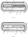
- FIGS. 1a and 1b are schematic diagrams of two kinds of electrode sheets being folded respectively.
- FIG. 1a shows a schematic diagram of a fold at a non-coated foil space after the winding machine completes a winding action, such a fold being caused by the failure to stretch the electrode sheet during a compaction stage under a tight adhesion between the separator and the copper foil at the head of the electrode sheet.
- the first folding at the head of the electrode sheet will show an overlap similar to that indicated by the arrow in FIG. 1a (the location and size of the overlap are not limited to those shown in FIG. la). It can be seen that the overlap is a thin line with a darker color and a width of about 0-1 mm when observed under X-ray.
- FIG. 1a the location and size of the overlap are not limited to those shown in FIG. la.
- FIG. 1b shows a schematic diagram of a folding because the electrode sheet cannot be stretched in time after the winding machine completes the winding action, in which the electrode sheet cannot be stretched in time, which is caused by an inconsistent force release on both sides of the single-sided paste-coated surface during the compaction stage of the wound core under a tight adhesion between the separator and the copper foil at the head of the electrode sheet.
- the single-sided paste-coated surface at the head of the electrode sheet will appear an overlap similar to that indicated by the arrow in FIG. 1b (the location and size of the overlap are not limited to those shown in FIG. 1b ).
- the overlap is observed under X-ray, it can be seen that it is a thin line with a darker color and a width of about 0-1 mm. Folding of electrode sheet will easily lead to potential safety hazards in the batteries.
- the purpose of this invention is to provide a lithium battery, which can reduce the phenomenon of poor production such as the folding of electrode sheet, and improve the yield of lithium batteries.
- a lithium battery includes a wound core and tabs, in which the wound core is formed by stacking and winding an inner separator, a first electrode sheet, an outer separator, and a second electrode sheet, and the first electrode sheet and the second electrode sheet have opposite polarity; the inner separator is located at the innermost layer of the wound core, and each of the inner separator and the outer separator has a clamping section, a first straight section connected with and located behind the clamping section, and a tail laminating section extending beyond a tail end of the first electrode sheet, where the first straight section is located in front of the first electrode sheet, and the tail laminating section is a separator end, and the clamping section, the first straight section and the tail laminating section of the inner separator are respectively laminated with the clamping section, the first straight section and the tail laminating section of the outer separator, and a dry peeling force of each of the first straight section of the inner separator and the first straight section of the outer separator is less than 8 N/m.
- the dry peeling force is determined by the following steps:
- the dry peeling force is a dry peeling force of a ceramic surface of the separator.
- each of the inner separator and the outer separator includes a base film, a ceramic layer and an adhesive layer, and a surface of the base film is provided with the ceramic layer or the adhesive layer, and an outer surface of the ceramic layer is provided with the adhesive layer; and a surface of the separator having both the ceramic layer and the adhesive layer is a ceramic surface, and at least one surface of each of the inner separator and the outer separator is the ceramic surface.
- surfaces of the inner separator and of the outer separator that are opposite to each other on the clamping section, the first straight section and the tail laminating section are ceramic surfaces.
- each of the inner separator and the outer separator includes a base film and an adhesive layer, and a surface of the base film on which the adhesive layer is disposed is an adhesive surface, and at least one surface of each of the inner separator and the outer separator is the adhesive surface.
- surfaces of the inner separator and of the outer separator that are opposite to each other on the clamping section, the first straight section and the tail laminating section are the adhesive surfaces.
- a length of the clamping section of the inner separator and a length of the clamping section of the outer separator are each 1-15% of a width of the wound core.
- a length of the first straight section of the inner separator and a length of the first straight section of the outer separator are each 40-50% of a width of the wound core.
- a length of the tail laminating section of the inner separator and a length of the tail laminating section of the outer separator are each ⁇ 5 mm.
- the length of the tail laminating section of the inner separator and the length of the tail laminating section of the outer separator are each 0.1-10% of the width of the wound core.
- a dry peeling force of each of the first straight section of the inner separator and the first straight section of the outer separator is less than 5 N/m.
- both the inner separator and the outer separator have an adhesive transfer area ratio of 20-40%, the adhesive transfer area ratio is a ratio of an adhesive transfer mass to a separator area, and the adhesive transfer mass is calculated by subtracting a separator mass after dry peeling from a separator mass before dry peeling.
- the wound core of the lithium battery of this invention is prepared by using the separator in which its first straight section has a specific dry peeling force, so that the separator is matched with other materials, the winding machine can stably output the product, and a battery structure with a folded rate of electrode sheets meeting the quality requirements is obtained, which is conducive to improve product yield and production efficiency.
- the dry peeling force of the separator (the adhesion force of separator coating) may be determined by directly the hot-pressing and compounding the separators, and then using an electronic universal testing machine to perform a peeling force test on the adhesive layers or the ceramic layers of the separator.
- the measured peeling force can be used to judge the battery hardness in the subsequent process in advance, and identify the adhesion force between respective main materials in the cell in advance, so as to select the separator material with the dry peeling force meeting the requirements, and then output the batteries with better hardness and better performance.
- ceramic particles and an adhesive polymer are contained in the ceramic layer; and the content of the ceramic particles is 85-92%.
- the ceramic particles are one or more of alumina, boehmite, and magnesia.
- the adhesive polymer is at least one of polyvinylidene fluoride, polyvinylpyrrolidone, vinylidene fluoride-hexafluoropropylene polymer, polyacrylonitrile, sodium carboxymethyl cellulose, sodium polyacrylate, polyacrylic acid, polyacrylate, styrene-butadiene copolymer, butadiene-acrylonitrile polymer, polyvinyl alcohol, polymethyl acrylate, polymethyl methacrylate, polyethyl acrylate, and polyacrylic acid-styrene polymer.
- D10 particle size is 0.15-0.3 ⁇ m
- D50 particle size is 0.35-0.45 ⁇ m
- D90 particle size is 0.6-0.8 ⁇ m
- D100 particle size is less than 4.5 ⁇ m.
- the adhesive layer includes an adhesive polymer
- the adhesive polymer is at least one of polyvinylidene fluoride, polyvinylpyrrolidone, vinylidene fluoride-hexafluoropropylene polymer, polyacrylonitrile, sodium carboxymethyl cellulose, sodium polyacrylate, polyacrylic acid, polyacrylate, styrene-butadiene copolymer, butadiene-acrylonitrile polymer, polyvinyl alcohol, polymethyl acrylate, polymethyl methacrylate, polyethyl acrylate and polyacrylic acid-styrene polymer.
- the adhesive layer has a thickness of 0.5 ⁇ m to 3 ⁇ m, and a packing density of 0.6 g/m 2 to 3.0 g/m 2 .
- the separator is a water-based separator
- the adhesive layer includes an adhesive polymer, a binder and a dispersing agent, in which the content of the adhesive polymer is 92-96%, and the content of the binder is 2.5-5.5%, and the content of the dispersing agent is 1.5-2.5%; or, the separator is an oil-based mixed-coating separator, and the adhesive layer includes an adhesive polymer and ceramic particles, in which the content of the adhesive polymer is 30-50%, and the content of the ceramic particles is 50-70%; or, the separator is a pure oil-based separator, and the adhesive layer includes an adhesive polymer, and the adhesive polymer has a molecular weight of 0.3 million to 1 million.
- a lithium battery includes a wound core and tabs.
- the wound core is formed by stacking a positive electrode sheet (a first electrode sheet), a negative electrode sheet (a second electrode sheet) and a separator together, and then winding them.
- the separator is located between the positive electrode sheet and the negative electrode sheet.
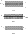
- the separator of the lithium battery includes a base film 11, a ceramic layer 12 provided on one or both sides of the base film 11, and an adhesive layer 13 located at the outermost layer of the separator.
- the separator shown in FIG. 2 has the ceramic layer 12 only provided on one surface of the base film 11 and adhesive layer 13 provided on the other surface of the base film 11, and an outer surface of the ceramic layer 12 is also provided with the adhesive layer 13.
- the separator of this embodiment has a structure of the base film + single-layer ceramic layer + double-sided adhesive layer.
- a surface of the separator with both the ceramic layer and the adhesive layer is defined as a ceramic surface, and a surface of the separator only with the adhesive layer is defined as an adhesive surface or a substrate surface.
- the base film may be a single-layer PE (polyethylene) film or a single-layer PP (polypropylene) film or a three-layer PP-PE-PP film structure, and a thickness of the base film may be 3 ⁇ m-20 ⁇ m.
- a thickness of the ceramic layer may be 0.5 ⁇ m-3 ⁇ m; and when both sides of the separator are provided with the ceramic layers, the thickness of the ceramic layer may be 0.5 ⁇ m-5 ⁇ m.
- the ceramic layer contains ceramic particles and an adhesive polymer, and the ceramic particles may be alumina, boehmite, magnesium oxide, and the adhesive polymer is at least one of polyvinylidene fluoride, polyvinylpyrrolidone, vinylidene fluoride-hexafluoropropylene polymer, polyacrylonitrile, sodium carboxymethyl cellulose, sodium polyacrylate, polyacrylic acid, polyacrylate, styrene-butadiene copolymer, butadiene-acrylonitrile polymer, polyvinyl alcohol, polymethyl acrylate, polymethyl methacrylate, polyethyl acrylate and polyacrylic acid-styrene polymer.
- the adhesive polymer is at least one of polyvinylidene fluoride, polyvinylpyrrolidone, vinylidene fluoride-hexafluoropropylene polymer, polyacrylonitrile, sodium carboxymethyl cellulose, sodium polyacrylate, polyacrylic acid, polyacrylate
- the content (mass percentage) of ceramic particles is 85-92%, with a balance of adhesive polymer.
- the particle size distribution of the ceramic particles is: D10 particle size being 0.15-0.3 ⁇ m, D50 particle size being 0.35-0.45 ⁇ m, D90 particle size being 0.6 -0.8 ⁇ m, D100 particle size being less than 4.5 ⁇ m.
- the adhesive layer has a thickness of 0.5 ⁇ m-3 ⁇ m and a packing density of 0.6 g/m 2 -3.0 g/m 2 , and the adhesive layer contains the adhesive polymer, and the adhesive polymer is at least one of polyvinylidene fluoride, polyvinylpyrrolidone, vinylidene fluoride-hexafluoropropylene polymer, polyacrylonitrile, sodium carboxymethyl cellulose, sodium polyacrylate, polyacrylic acid, polyacrylate, styrene-butadiene copolymer, butadiene-acrylonitrile polymer, polyvinyl alcohol, polymethyl acrylate, polymethyl methacrylate, polyethyl acrylate, and polyacrylic acid-styrene polymer.
- the adhesive polymer is at least one of polyvinylidene fluoride, polyvinylpyrrolidone, vinylidene fluoride-hexafluoropropylene polymer, polyacrylonitrile
- the adhesive layer includes the adhesive polymer, a binder and a dispersing agent, in which the content (mass percentage) of the adhesive polymer is 92-96%, and the content of the binder is 2.5-5.5%, and the content of the dispersing agent is 1.5-2.5%.
- the adhesive layer includes an adhesive polymer and ceramic particles, in which, the adhesive polymer has a content (mass percentage) of 30-50% and the content of the ceramic particles is 50-70%.
- the separator is a pure oil-based separator, the content of the adhesive polymer in the adhesive layer is 100%, and the adhesive polymer has a molecular weight of 0.3 to 1 million.
- the positive electrode sheet of the lithium battery includes a positive electrode foil 14 and positive electrode active material layers 15 coated on both sides of the positive electrode foil 14.
- the positive electrode foil 14 may be an aluminum foil and have a thickness of 8 ⁇ m-14 ⁇ m.
- the positive electrode active material layer includes a positive electrode material, a conductive agent and a binder
- the positive electrode material may be one of LiCoO 2 , LiNiO 2 , LiFePO 4 , LiMn 2 O 4 , and LiNi x Co y Mn 1-x-y O 2
- the conductive agent may be one or more of conductive carbon black, carbon nanotube, conductive graphite and graphene
- the binder may be one or more of polyvinylidene fluoride, vinylidene fluoride-fluorinated olefin copolymer, polytetrafluoroethylene, sodium carboxymethyl cellulose, styrene-butadiene rubber, polyurethane, fluorinated rubber and polyvinyl alcohol.
- the positive electrode material has a content (mass percentage) of 96-98.5%
- the conductive agent has a content of 0.5-2.5%
- the binder has a content of 1-1.5%
- the negative electrode sheet of the lithium battery includes a negative electrode foil 16 and negative electrode active material layers 17 coated on both sides of the negative electrode foil 16.
- the negative electrode foil 16 may be a copper foil, and have a thickness of 5 ⁇ m-10 ⁇ m.
- the negative electrode active material layer includes a negative electrode material, a conductive agent, a binder and a dispersing agent.
- the negative electrode material may be one or more of mesophase carbon microsphere, artificial graphite, natural graphite, hard carbon, soft carbon, lithium titanate, silicon-based material, tin-based material and lithium metal; and the conductive agent may be conductive carbon black, carbon nanotube, conductive graphite and graphene; the binder may be one or more of polyvinylidene fluoride, vinylidene fluoride-fluorinated olefin copolymer, polytetrafluoroethylene, sodium carboxymethyl cellulose, styrene-butadiene rubber, polyurethane, fluorinated rubber, and polyvinyl alcohol; and the dispersing agent may be sodium carboxymethyl cellulose or potassium carboxymethyl cellulose.
- the content (mass percentage) of the negative electrode material is 95-97%, and the content of the conductive agent is 1-2%, and the content of the binder is 1-1.5%, and the content of the dispersing agent is 0-1.5%.
- a rolling needle A clamps heads of two layers of separators and drives the separators to rotate.
- the thick dotted line represents a separator located at an inner side of the two layers of separators - an inner separator B1, where the inner separator B1 is in contact with the rolling needle A; and the thin dotted line represents a separator located at an outer side of the two layers of separators - an outer separator B2, where the outer separator B2 is stacked on the outside of the inner separator B1 and not in direct contact with the rolling needle A.
- the rolling needle A will clamp the heads of the two layers of separators, and a part of each separator that is clamped by the rolling needle is defined as a clamping section; and the clamping section of the inner separator B1 and the clamping section of the outer separator are stacked together, for example, a part located in the wireframe a as shown in FIG. 5a .
- a part before first bending of the separators is defined as a first straight section, which is located behind the clamping section, and the first straight section of the inner separator B1 and the first straight section of the outer separator B2 is stacked together, for example, a part located in the wireframe b as shown in FIG.
- a negative electrode pressing roller presses against a negative electrode sheet C (the thick solid line in FIG. 5a represents the negative electrode sheet), and the negative electrode sheet C is introduced by the separators and located between the inner separator B1 and the outer separator B2.
- a positive electrode pressing roller presses against a positive electrode sheet D (the thin solid line in FIG. 5a represents the positive electrode sheet), and the positive electrode sheet D is introduced along the separators, so that the positive electrode sheet D and the negative electrode sheet C are separated by the separators, and the early-stage winding action is completed.
- the positive and negative electrode pressing rollers are retracted, and the positive and negative electrode sheets rotate with the rotation of the separators to obtain a wound core, forming a winding structure which has a layer of separator - a layer of negative electrode sheet - a layer of separator - a layer of positive electrode sheet.
- another winding process may also be used, that is, after the rolling needle clamps the clamping section of the separators and rotates for half a circle, the positive and negative electrode sheets are simultaneously introduced to form a winding structure having a layer of separator - a layer of positive electrode sheet - a layer of separator - a layer of negative electrode sheet.
- tails of the two layers of separators both extend beyond a tail of the positive electrode sheet, and the tails of the two layers of separators have a part overlapped and laminated together, in which end parts of the two layers of separators that extend beyond the positive electrode sheet and laminated together are each defined as a tail laminating section, for example, a part indicated by arrow Q as shown in FIG. 5b .
- parts of the inner separator B1 that are in direct contact with the rolling needle will be overlapped and contacted with each other together due to the drawing out of the rolling needle; the parts of the inner separator B1 that overlap with each other after the rolling needle A is drawn out are defined as a first inner-layer laminating section, for example, parts as indicated by arrow P in FIG. 5b .
- the wound core shown in FIG. 5b has two structures.
- One structure is: a surface of the separator opposite to the rolling needle is the ceramic surface, and the opposite surfaces between the two adjacent separator layers are adhesive surfaces (the part in the wireframe a and the part in the wireframe b in FIG. 5a , and the part indicated by the arrow Q in FIG. 5b ); after the rolling needle is drawn out, the clamping section of the inner separator B1 will be opposite to the first straight section thereof, that is, the ceramic surface of the clamping section is opposite to the ceramic surface of the first straight section.
- Another structure is: the surface of the separator opposite to the rolling needle is the adhesive surface, and the opposite surfaces between the two adjacent separator layers are ceramic surfaces; after the rolling needle is drawn out, the clamping section of the inner separator B1 will be opposite to the first straight section thereof, that is, the adhesive surface of the clamping section is opposite to the adhesive surface of the first straight section. That is, in the two structures, the opposite surfaces between the two adjacent separator layers are made of the same material, and the opposite surfaces formed by the overlapping of the inner separator itself are also made of the same material.
- a length of the clamping section of the separator is 1-15% of a width of the wound core
- a length of the first straight section of the separator is 40-50% of the width of the wound core
- the tail laminating section of the separator has a length of at least 5 mm, which is 0.1-10% of the width of the wound core.
- the separator When the adhesive force of the separator is relatively large, the separator is more prone to stick to the rolling needle during the preparation process of the wound core, resulting in the phenomenon of the folding of non-coated foil ( FIG. 1a ) and/or the folding of electrode sheets ( FIG. 1b ) when winding. Moreover, due to the excessive shrinkage of the separator at room temperature (standard shrinkage ⁇ 0.3%), the separator will also be adhered to or adsorbed on a newly introduced negative electrode, resulting in a Hi-Pot hot pressing of the wound core, thereby the phenomena of the folding of non-coated foil of the electrode sheet and/or the folding of negative electrode sheet at a single-sided area of the head of the wound core occur.
- the separator based on the above structure includes a selection of separator material, a setting of material components, and a structural arrangement of each layer of the separator
- a specific dry peeling force being equal to the adhesive force of the surface coating of the separator
- the dry peeling force it is possible to identify the adhesive force between the separators and between the separator and the positive and negative electrodes in advance, judge whether the separator can meet the adhesive requirements after the hot-pressing and formation of the cell in advance, identify the adhesion force between the main materials of the cell in advance, and select a separator with a specific dry peeling force to prepare the wound core of battery, thereby reducing production abnormalities such as folded electrode sheet, and yielding a battery with better hardness and better performance.
- the dry peeling force in this invention is characterized by performing a 90° peeling on the separators after the separators are hot-pressed and compounded in an electrolyte-free environment, in which such peeling force is called the dry peeling force.
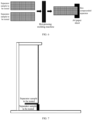
- the separator to be tested is cut into separator samples with suitable size; for example, the separator to be tested is cut into a long strip with a certain width, such as a small strip with a width of 15 mm. Two cut pieces of separator samples to be tested are aligned and stacked, and a paper sheet is introduced at one end of stacked samples so as to separate the two pieces of separator samples to be tested. For example, when the separator on the clamping section is tested, the inner separator and outer separator that are laminated together at the clamping section are cut into samples, followed by aligning and stacking.
- thermoplastic machine in this embodiment, the thermoplastic machine used has a model of SKY-325R6, and a hot pressing temperature is 100°C, a surface pressure is 0.2 MPa, and a hot pressing time is 10 s.
- an electronic universal testing machine is used to perform a 90° peel test on the separator samples to be tested, in which one end of one piece of the separator sample to be tested is fixed with a moving end of the electronic universal testing machine, and one end of the other piece of separator sample to be tested is fixed with a fixing end of the electronic universal testing machine, and the preload speed and the test speed are set to 100 mm/min, and the two pieces of separator samples to be tested are separated ( FIG. 7 ), and the peeling force during separation of the separator samples to be tested is recorded.
- This invention evaluates the adhesive force between the separator coatings by the dry peeling force, therefore, when the dry peeling force between the separators is tested, the separators with same material that are pressed together are separated, in which the two separators have the same coating, instead of using auxiliary materials with different surface materials such as quick-drying adhesive and double-sided tape, so that more accurate data on the adhesive force of the separator surface coatings may be obtained.
- the samples to be tested are pressed and compounded together by hot pressing, which is simple and quick to operate, and the 90° peel test is more convenient than a 180° peel test which requires the aid of other auxiliary materials.
- EJ oil-based separator (26 m/min) Adhesive surface (N/m) Ceramic surface (N/m) EJ oil-based separator (16 m/min) Adhesive surface (N/m) Ceramic surface (N/m) Oil-based separator with large holes Adhesive surface (N/m) Ceramic surface (N/m) EJ oil-based separator 1 18.4 12.1 EJ oil-based separator 5 16.6 8.0 Oil-based separator with large holes 1 3.9 3.8 EJ oil-based separator 2 19.9 12.7 EJ oil-based separator 6 18.3 10.7 Oil-based separator with large holes 2 2.2 1.8 EJ oil-based separator 3 18.1 11.8 EJ oil-based separator 7 16.3 5.4 Oil-based separator with large holes 3 3.9 2.8 EJ oil-based separator 4 19.1 12.4 EJ oil-based separator 8 15.4 9.4 Oil-based separator with large holes 4 4.2
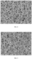
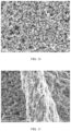
- FIG. 8 and FIG. 9 are SEM images of the substrate surfaces of the EJ oil-based separator 5 and the EJ oil-based separator 1 before hot pressing, respectively.
- the SEM images of the substrate surfaces of the EJ oil-based separators 6-8 before hot pressing are similar to that of FIG.
- the SEM images of the substrate surfaces of the EJ oil-based separators 2-4 before hot pressing are similar to that of FIG. 9 .
- part of each cell is subjected to quality inspection, including the folding of the separator and the peeling and transfer of the coating.
- the inspection results are shown in the following table.
- the distance of electrode sheet covered by the separator refers to the over-covering size of the separator to the negative electrode sheet, which is used to prevent the short circuit inside the cell.
- a transfer area is further used to determine the transfer performance during the dry peeling of the separator, as another performance parameter to select a suitable separator.
- the transfer area is larger, the adhesiveness is greater, the adhesion between the electrode sheets of the cell and the separator is greater, and accordingly, the winding is more difficult, and the ratio of removed core and poor spacing is larger, and the possibility of folding is more, and the battery has more hardness.
- the dry peeling force of the adhesive surface is greater than that of the ceramic surface, so the dry peeling force of the ceramic surface may be used for selecting separator material.
- the ceramic surface and the substrate surface of the separator both show an effect of SEM images similar to FIG. 10 to FIG. 13 ; the phenomenon of peeling and transfer appears at the adhesive layer of the ceramic surface or the substrate surface of the separator, in which the transfer area is reduced to 20% to 40%.
- the manufacturing process of the wound core is stable, and the folding of the electrode sheet and the non-coated foil rarely occurs in the wound cell when the wound cell is removed from the working table during the winding process, and the phenomena of non-coated foil and folded electrode sheet rarely occur during the hot-pressing or drying of the wound core, and the ceramic surface and the substrate surface of the separator after peeling do not appear the effect of SEM images shown in FIG. 10 to FIG. 13 .
- the adhesion effect will occur after the wound core is compacted, and the phenomenon of separator adhesion is also prone to occur at the area of the separator beyond the negative electrode, which makes the separator have an improved adhesion effect, show better adhesive performance during hot pressing and formation in subsequent process, and realize the adhesion between the separators and the positive and negative electrode sheets.
- the battery has a better hardness, and the separators at the head and bottom of the wound core in the cell have a better contact adhesion during hot pressing and formation, and the internal short circuit caused by the contact of the positive and negative electrodes may be avoided when the cell is subjected to a furnace temperature test for the safety performance.
- the electrode sheet or the separator is folded, the safety performance of the cell will be reduced.
- the separator is selected according to the dry peeling force of the separator surface, and the dry peeling forces of the first straight section of the inner separator and the first straight section of the outer separator in the wound core of the lithium battery are each less than 8 N/m, thereby improving the folding phenomenon of the electrode sheet.
- the first straight section of the separator have a low dry peeling force, the phenomenon of the folding of the electrode sheet is improved, without affecting the adhesion of other parts of the separator, so as to ensure the hardness of the battery.
- the dry peeling force is the dry peeling force of the ceramic surface of the separator.
- the separator material is selected according to the dry peeling force, which is convenient for the control of the separator coating and is capable of identifying the adhesive effect between the separator layers in time; and the separator material is selected to match the rolling needle (Teflon) based on the dry peeling force.
- Teflon rolling needle
- the dry peeling force in this invention is determined by testing the peeling force between the separator coatings with an electronic universal testing machine after the separators are hot-pressed, so the hardness of the battery in subsequent process may be identified at a primary stage of winding by the dry peeling force between layers, and the adhesion force between the respective main materials of the cell may be identified in advance, and furthermore the battery with better hardness and better performance can be obtained.
- the dry peeling force may be used as an incoming management method for the separator coatings to identify a macroscopic index of separator incoming in time, and further determine whether the separator incoming is capable of meeting the adhesive performance of the cell after being hot pressed and subjected to formation.
Landscapes
- Chemical & Material Sciences (AREA)
- Chemical Kinetics & Catalysis (AREA)
- Electrochemistry (AREA)
- General Chemical & Material Sciences (AREA)
- Engineering & Computer Science (AREA)
- Manufacturing & Machinery (AREA)
- Inorganic Chemistry (AREA)
- Ceramic Engineering (AREA)
- Materials Engineering (AREA)
- Cell Separators (AREA)
Applications Claiming Priority (2)
| Application Number | Priority Date | Filing Date | Title |
|---|---|---|---|
| CN202011451375.1A CN112563583B (zh) | 2020-12-10 | 2020-12-10 | 锂电池 |
| PCT/CN2021/137219 WO2022122031A1 (zh) | 2020-12-10 | 2021-12-10 | 锂电池 |
Publications (2)
| Publication Number | Publication Date |
|---|---|
| EP4160780A1 true EP4160780A1 (de) | 2023-04-05 |
| EP4160780A4 EP4160780A4 (de) | 2024-10-09 |
Family
ID=75061670
Family Applications (1)
| Application Number | Title | Priority Date | Filing Date |
|---|---|---|---|
| EP21902736.4A Pending EP4160780A4 (de) | 2020-12-10 | 2021-12-10 | Lithiumbatterie |
Country Status (4)
| Country | Link |
|---|---|
| US (1) | US20230223582A1 (de) |
| EP (1) | EP4160780A4 (de) |
| CN (1) | CN112563583B (de) |
| WO (1) | WO2022122031A1 (de) |
Families Citing this family (6)
| Publication number | Priority date | Publication date | Assignee | Title |
|---|---|---|---|---|
| CN112563583B (zh) * | 2020-12-10 | 2022-04-29 | 珠海冠宇电池股份有限公司 | 锂电池 |
| CN112563584B (zh) * | 2020-12-10 | 2022-04-19 | 珠海冠宇电池股份有限公司 | 一种锂电池 |
| CN113363595B (zh) * | 2021-06-02 | 2023-02-21 | 深圳吉阳智能科技有限公司 | 动力锂离子电池和动力锂离子电池的制备方法 |
| CN218919208U (zh) * | 2022-10-31 | 2023-04-25 | 珠海冠宇电池股份有限公司 | 一种隔膜及电芯 |
| CN115954522B (zh) * | 2023-01-06 | 2026-03-10 | 欣旺达动力科技股份有限公司 | 卷芯整形系统及方法 |
| CN116780107A (zh) * | 2023-06-30 | 2023-09-19 | 珠海冠宇电池股份有限公司 | 隔膜和电池 |
Family Cites Families (21)
| Publication number | Priority date | Publication date | Assignee | Title |
|---|---|---|---|---|
| JP2010244875A (ja) * | 2009-04-07 | 2010-10-28 | Panasonic Corp | リチウム二次電池用セパレータ、およびそれを用いたリチウム二次電池 |
| KR101625717B1 (ko) * | 2013-09-27 | 2016-05-30 | 주식회사 엘지화학 | 이차전지용 단위체 적층장치 및 적층방법 |
| CN205828578U (zh) * | 2016-07-08 | 2016-12-21 | 宁德新能源科技有限公司 | 二次电池卷绕式电芯 |
| CN207199769U (zh) * | 2016-08-10 | 2018-04-06 | 宁德时代新能源科技股份有限公司 | 锂离子电池及其电芯 |
| CN106207059B (zh) * | 2016-08-12 | 2020-02-21 | 联想(北京)有限公司 | 一种锂离子电池隔膜、其制备方法和应用 |
| JP2017103211A (ja) * | 2016-09-02 | 2017-06-08 | 住友化学株式会社 | 非水電解液二次電池用セパレータおよびその利用 |
| CN206401456U (zh) * | 2016-12-27 | 2017-08-11 | 宁德新能源科技有限公司 | 一种卷绕式电芯 |
| CN106953052A (zh) * | 2017-03-16 | 2017-07-14 | 上海双奥能源技术有限公司 | 一种锂离子电池隔膜的制备方法 |
| CN108390101B (zh) * | 2018-01-03 | 2020-06-23 | 多氟多新能源科技有限公司 | 一种锂离子电池电芯及其制备方法、锂离子电池 |
| JP2019121508A (ja) * | 2018-01-04 | 2019-07-22 | 三井化学株式会社 | 二次電池用セパレータ、これを含む二次電池用積層体およびその製造方法、捲回体、二次電池、ならびに塗工用樹脂組成物 |
| CN110148695B (zh) * | 2019-04-26 | 2020-12-29 | 东莞东阳光科研发有限公司 | 一种电池隔膜的制备方法 |
| CN109994695B (zh) * | 2019-05-29 | 2019-10-22 | 东莞东阳光科研发有限公司 | 聚合物浆料、复合隔膜及其制备方法 |
| CN111354907A (zh) * | 2020-03-23 | 2020-06-30 | 安徽新衡新材料科技有限公司 | 一种pmma聚合物涂层隔膜及其制备方法 |
| CN111293347B (zh) * | 2020-04-08 | 2023-03-28 | 湖北亿纬动力有限公司 | 一种电池生产工艺 |
| CN211789341U (zh) * | 2020-05-20 | 2020-10-27 | 宁德新能源科技有限公司 | 电芯、应用所述电芯的电池及电子装置 |
| WO2021232314A1 (zh) * | 2020-05-20 | 2021-11-25 | 宁德新能源科技有限公司 | 电极组件和电池 |
| CN111725569B (zh) * | 2020-06-24 | 2022-05-13 | 珠海冠宇电池股份有限公司 | 一种卷芯和电池 |
| CN111916621A (zh) * | 2020-08-19 | 2020-11-10 | 北京宇程科技有限公司 | 一种锂离子电池用耐高温复合隔膜及其制备方法 |
| CN112563665B (zh) * | 2020-12-10 | 2023-06-02 | 珠海冠宇电池股份有限公司 | 一种锂离子电池 |
| CN112563584B (zh) * | 2020-12-10 | 2022-04-19 | 珠海冠宇电池股份有限公司 | 一种锂电池 |
| CN112563583B (zh) * | 2020-12-10 | 2022-04-29 | 珠海冠宇电池股份有限公司 | 锂电池 |
-
2020
- 2020-12-10 CN CN202011451375.1A patent/CN112563583B/zh active Active
-
2021
- 2021-12-10 EP EP21902736.4A patent/EP4160780A4/de active Pending
- 2021-12-10 WO PCT/CN2021/137219 patent/WO2022122031A1/zh not_active Ceased
-
2022
- 2022-12-30 US US18/148,966 patent/US20230223582A1/en active Pending
Also Published As
| Publication number | Publication date |
|---|---|
| WO2022122031A1 (zh) | 2022-06-16 |
| CN112563583B (zh) | 2022-04-29 |
| EP4160780A4 (de) | 2024-10-09 |
| CN112563583A (zh) | 2021-03-26 |
| US20230223582A1 (en) | 2023-07-13 |
Similar Documents
| Publication | Publication Date | Title |
|---|---|---|
| US20230223582A1 (en) | Lithium battery | |
| US20230147863A1 (en) | Lithium-ion battery | |
| US20230138917A1 (en) | Lithium battery | |
| JP4362539B2 (ja) | 電池用電極板、電池用極板群、リチウム二次電池、電池用電極板の製造方法、及び電池用電極板の製造装置 | |
| EP1653532B1 (de) | Verfahren zum herstellen einer lithium-ionen-sekundärbatterie | |
| JP4527190B1 (ja) | 非水系電池用正極板、非水系電池用電極群およびその製造方法、並びに、角形非水系二次電池およびその製造方法 | |
| KR102018299B1 (ko) | 리튬 이차전지용 분리막 및 그의 제조방법 | |
| JP4527191B1 (ja) | 非水系電池用電極群およびその製造方法並びに円筒形非水系二次電池およびその製造方法 | |
| CN104681858B (zh) | 一种超薄柔性锂离子电池及其制备方法 | |
| JP2002025624A (ja) | リチウム二次電池の製造方法 | |
| JP2010186740A (ja) | 非水系電池用電極群およびその製造方法並びに円筒形非水系二次電池およびその製造方法 | |
| JP2010186736A (ja) | 非水系電池用負極板、非水系電池用電極群およびその製造方法、並びに、円筒形非水系二次電池およびその製造方法 | |
| EP4625567A2 (de) | Sekundärbatterie und elektronische vorrichtung | |
| CN119230921A (zh) | 一种全固态电芯及其制备方法和应用 | |
| JP4527189B1 (ja) | 非水系電池用正極板、非水系電池用電極群およびその製造方法、並びに、角形非水系二次電池およびその製造方法 | |
| JP7802017B2 (ja) | デジタル電池のセパレータ及びその作製方法 | |
| CN118367205B (zh) | 一种固态锂离子电池及其制备方法 | |
| CN108717967A (zh) | 一种超薄电芯及制备方法、超薄锂离子电池及制备方法 | |
| JP2022172514A (ja) | 二次電池用電極、及びこれを備える固体電池、並びに二次電池用電極の製造方法 | |
| CN115051110B (zh) | 一种补锂复合隔离膜及其制备方法、补锂装置与应用 | |
| CN116202955A (zh) | 一种表征电池极片中粘结剂分布的方法 | |
| EP4239736A1 (de) | Batterieseparator und beschichtungsverfahren und beschichtungssystem dafür sowie batterie | |
| CN116525750B (zh) | 一种正极片及其干法制备工艺 | |
| CN119581692B (zh) | 二次电池及用电装置 | |
| CN118970062B (zh) | 干法电极集流体、其制备方法、干法电极极片及二次电池 |
Legal Events
| Date | Code | Title | Description |
|---|---|---|---|
| STAA | Information on the status of an ep patent application or granted ep patent |
Free format text: STATUS: THE INTERNATIONAL PUBLICATION HAS BEEN MADE |
|
| PUAI | Public reference made under article 153(3) epc to a published international application that has entered the european phase |
Free format text: ORIGINAL CODE: 0009012 |
|
| STAA | Information on the status of an ep patent application or granted ep patent |
Free format text: STATUS: REQUEST FOR EXAMINATION WAS MADE |
|
| 17P | Request for examination filed |
Effective date: 20230102 |
|
| AK | Designated contracting states |
Kind code of ref document: A1 Designated state(s): AL AT BE BG CH CY CZ DE DK EE ES FI FR GB GR HR HU IE IS IT LI LT LU LV MC MK MT NL NO PL PT RO RS SE SI SK SM TR |
|
| DAV | Request for validation of the european patent (deleted) | ||
| DAX | Request for extension of the european patent (deleted) | ||
| A4 | Supplementary search report drawn up and despatched |
Effective date: 20240909 |
|
| RIC1 | Information provided on ipc code assigned before grant |
Ipc: H01M 50/417 20210101ALI20240903BHEP Ipc: H01M 50/406 20210101ALI20240903BHEP Ipc: H01M 10/052 20100101ALI20240903BHEP Ipc: H01M 50/451 20210101ALI20240903BHEP Ipc: H01M 50/434 20210101ALI20240903BHEP Ipc: H01M 50/46 20210101ALI20240903BHEP Ipc: H01M 50/457 20210101ALI20240903BHEP Ipc: H01M 10/0525 20100101ALI20240903BHEP Ipc: H01M 10/0587 20100101AFI20240903BHEP |