EP4160876B1 - Wicklungen für elektrische maschinen - Google Patents
Wicklungen für elektrische maschinen Download PDFInfo
- Publication number
- EP4160876B1 EP4160876B1 EP21275144.0A EP21275144A EP4160876B1 EP 4160876 B1 EP4160876 B1 EP 4160876B1 EP 21275144 A EP21275144 A EP 21275144A EP 4160876 B1 EP4160876 B1 EP 4160876B1
- Authority
- EP
- European Patent Office
- Prior art keywords
- conductors
- winding
- conductor
- pair
- electrical machine
- Prior art date
- Legal status (The legal status is an assumption and is not a legal conclusion. Google has not performed a legal analysis and makes no representation as to the accuracy of the status listed.)
- Active
Links
Images


Classifications
-
- H—ELECTRICITY
- H02—GENERATION; CONVERSION OR DISTRIBUTION OF ELECTRIC POWER
- H02K—DYNAMO-ELECTRIC MACHINES
- H02K3/00—Details of windings
- H02K3/04—Windings characterised by the conductor shape, form or construction, e.g. with bar conductors
- H02K3/12—Windings characterised by the conductor shape, form or construction, e.g. with bar conductors arranged in slots
-
- B—PERFORMING OPERATIONS; TRANSPORTING
- B33—ADDITIVE MANUFACTURING TECHNOLOGY
- B33Y—ADDITIVE MANUFACTURING, i.e. MANUFACTURING OF THREE-DIMENSIONAL [3D] OBJECTS BY ADDITIVE DEPOSITION, ADDITIVE AGGLOMERATION OR ADDITIVE LAYERING, e.g. BY 3D PRINTING, STEREOLITHOGRAPHY OR SELECTIVE LASER SINTERING
- B33Y80/00—Products made by additive manufacturing
-
- B—PERFORMING OPERATIONS; TRANSPORTING
- B64—AIRCRAFT; AVIATION; COSMONAUTICS
- B64D—EQUIPMENT FOR FITTING IN OR TO AIRCRAFT; FLIGHT SUITS; PARACHUTES; ARRANGEMENT OR MOUNTING OF POWER PLANTS OR PROPULSION TRANSMISSIONS IN AIRCRAFT
- B64D27/00—Arrangement or mounting of power plants in aircraft; Aircraft characterised by the type or position of power plants
- B64D27/02—Aircraft characterised by the type or position of power plants
- B64D27/10—Aircraft characterised by the type or position of power plants of gas-turbine type
-
- B—PERFORMING OPERATIONS; TRANSPORTING
- B64—AIRCRAFT; AVIATION; COSMONAUTICS
- B64D—EQUIPMENT FOR FITTING IN OR TO AIRCRAFT; FLIGHT SUITS; PARACHUTES; ARRANGEMENT OR MOUNTING OF POWER PLANTS OR PROPULSION TRANSMISSIONS IN AIRCRAFT
- B64D27/00—Arrangement or mounting of power plants in aircraft; Aircraft characterised by the type or position of power plants
- B64D27/02—Aircraft characterised by the type or position of power plants
- B64D27/30—Aircraft characterised by electric power plants
- B64D27/33—Hybrid electric aircraft
-
- B—PERFORMING OPERATIONS; TRANSPORTING
- B64—AIRCRAFT; AVIATION; COSMONAUTICS
- B64D—EQUIPMENT FOR FITTING IN OR TO AIRCRAFT; FLIGHT SUITS; PARACHUTES; ARRANGEMENT OR MOUNTING OF POWER PLANTS OR PROPULSION TRANSMISSIONS IN AIRCRAFT
- B64D35/00—Transmitting power from power plants to propellers or rotors; Arrangements of transmissions
-
- F—MECHANICAL ENGINEERING; LIGHTING; HEATING; WEAPONS; BLASTING
- F02—COMBUSTION ENGINES; HOT-GAS OR COMBUSTION-PRODUCT ENGINE PLANTS
- F02C—GAS-TURBINE PLANTS; AIR INTAKES FOR JET-PROPULSION PLANTS; CONTROLLING FUEL SUPPLY IN AIR-BREATHING JET-PROPULSION PLANTS
- F02C6/00—Plural gas-turbine plants; Combinations of gas-turbine plants with other apparatus; Adaptations of gas-turbine plants for special use
-
- H—ELECTRICITY
- H02—GENERATION; CONVERSION OR DISTRIBUTION OF ELECTRIC POWER
- H02K—DYNAMO-ELECTRIC MACHINES
- H02K3/00—Details of windings
- H02K3/04—Windings characterised by the conductor shape, form or construction, e.g. with bar conductors
- H02K3/24—Windings characterised by the conductor shape, form or construction, e.g. with bar conductors with channels or ducts for cooling medium between the conductors
-
- B—PERFORMING OPERATIONS; TRANSPORTING
- B64—AIRCRAFT; AVIATION; COSMONAUTICS
- B64D—EQUIPMENT FOR FITTING IN OR TO AIRCRAFT; FLIGHT SUITS; PARACHUTES; ARRANGEMENT OR MOUNTING OF POWER PLANTS OR PROPULSION TRANSMISSIONS IN AIRCRAFT
- B64D27/00—Arrangement or mounting of power plants in aircraft; Aircraft characterised by the type or position of power plants
- B64D27/02—Aircraft characterised by the type or position of power plants
- B64D27/026—Aircraft characterised by the type or position of power plants comprising different types of power plants, e.g. combination of a piston engine and a gas-turbine
-
- Y—GENERAL TAGGING OF NEW TECHNOLOGICAL DEVELOPMENTS; GENERAL TAGGING OF CROSS-SECTIONAL TECHNOLOGIES SPANNING OVER SEVERAL SECTIONS OF THE IPC; TECHNICAL SUBJECTS COVERED BY FORMER USPC CROSS-REFERENCE ART COLLECTIONS [XRACs] AND DIGESTS
- Y02—TECHNOLOGIES OR APPLICATIONS FOR MITIGATION OR ADAPTATION AGAINST CLIMATE CHANGE
- Y02T—CLIMATE CHANGE MITIGATION TECHNOLOGIES RELATED TO TRANSPORTATION
- Y02T50/00—Aeronautics or air transport
- Y02T50/60—Efficient propulsion technologies, e.g. for aircraft
Definitions
- the present disclosure relates to windings for electrical machines.
- the present disclosure also relates to an electrical machine including the windings and an aircraft including the electrical machine.
- An electrical machine utilises electromagnetic forces to convert electrical energy to mechanical energy (referred to as an electric motor) or to convert mechanical energy to electrical energy (referred to as an electric generator).
- Electrical machines typically comprise a stationary stator, a rotor configured to rotate relative to the stator, and one or more windings formed by a coil of conductive material, for example copper, wrapped around portions of the stator.
- electric current is passed through the winding, which generates a magnetic field.
- a second magnetic field is generated by the rotor, either by permanent magnets or electromagnets/coils mounted thereon. The interaction between these two magnetic fields induces a torque on the rotor, thus causing the rotor to rotate relative to the stator.
- This operation may also be conducted in reverse, in that the rotor may be mechanically rotated to induce an electrical current in the winding.
- the winding may be mounted to the rotor instead of the stator.
- One use for electrical machines is to provide some or all of the energy required for the propulsion of a vehicle.
- the windings are typically mounted in slots in the stator, and are used to generate a magnetic field that interacts with magnetic fields associated with the rotor to produce torque on the rotor.
- Power requirements for high performance electrical propulsion motors can exceed 1 MW. Therefore, important factors for the design of such high performance electric propulsion motors are power density and specific power.
- a higher power density and/or specific power means that for a given power requirement, the motor can be smaller and lighter, which is particularly advantageous for electric propulsion motors in vehicles such as aircraft, where space and weight are key limiting factors.
- the windings of the electrical machine need to be able to carry as much power as possible. Unfortunately, AC losses and conductor overheating can restrict the power carrying capacity of the windings.
- AC losses may be caused by the skin effect, which is the tendency of a highfrequency alternating current to flow through only the outer layer of a conductor, caused by opposing eddy currents induced by the changing magnetic field resulting from the alternating current.
- the skin effect effectively limits the cross-sectional area of the conductor that can be utilized to carry current, and also increases with frequency.
- the reduction in current carrying cross-section can also contribute to conductor overheating. It is therefore desirable to employ conductor configurations that minimise such eddy current generation to improve the current carrying capacity and operating temperature for a given cross-section of conductor.
- the present disclosure aims to provide a winding with a conductor configuration that minimizes AC losses and allows effective cooling thereof to maximise power carrying capacity.
- a winding can improve the power density and/or specific power of an electrical machine. This may be particularly suited for electric propulsion motors used in aircraft applications, where there is a high power requirement, but weight and size are to be minimised where possible.
- the present disclosure provides a winding for an electrical machine according to claim 1.
- each conductor comprises a U-shaped cross-section defining a base and two sides each joined to a respective end of the base by a substantially 90 degree angle.
- one or both of the sides is approximately three times the length of the base.
- one of the sides is shorter than the other side.
- the U-shaped conductors in each pair of conductors are interleaved such that a cooling channel is formed between one of the sides of one of the pair of conductors and the base of the other of the pair of conductors.
- the U-shaped conductors in each pair of conductors are interleaved such that a substantially S-shaped gap separates the pair of conductors.
- the present disclosure provides a winding for an electrical machine according to claim 7.
- the long side is approximately three times the length of the short side.
- the present disclosure provides an electrical machine comprising a stator.
- the stator comprises a slot and the winding of the above aspect or any of its embodiments, disposed within the slot.
- the present disclosure provides an aircraft comprising the electrical machine of the above aspect.
- the aircraft further comprises a propeller, and the electrical machine is configured to drive the propeller.
- the aircraft further comprises a gas turbine engine, and the electrical machine is configured to supplement drive for the gas turbine engine.
- FIG. 1 shows one prior art arrangement.
- a winding comprises a conductor 10 having at least one turn forming the winding.
- the winding is mounted within a slot 12 in a stator 14.
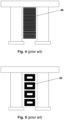
- the conductor 10 has a rectangular cross-section. Rectangular conductors are commonly used in high power applications, such as those discussed above, because they can carry a large current and are suitable for liquid cooling. However, AC losses can be particularly high in rectangular conductors due to the skin effect, which may also result in overheating.
- one known way of reducing AC losses caused by the skin effect is to form the conductor from multiple strands 20 having a smaller cross-section.
- one drawback of this configuration is that it reduces the ratio of the cross-sectional area of conductive material within the stator slot relative to the total cross-sectional area available within the slot. This is known as the slot fill factor.
- a lower slot fill factor reduces the current that can be passed through the winding, thus reducing power density and specific power. In this arrangement, cooling is also compromised, further reducing power density and specific power.
- one particularly effective way of reducing AC losses caused by the skin effect is to form the conductor from Litz wire 30, which is specifically designed to reduce losses caused by the skin effect.
- this configuration can compromise the slot fill factor and cooling even further relative to the previous multi-strand conductor 20.
- a known way of maintaining a high slot fill factor while reducing losses caused by the skin effect is to form the conductor from a plurality of flat wires 40.
- the flat wires 40 are stacked within the slot to increase the slot fill factor.
- the flat wires 40 may not be suitable for applications which require liquid cooling, as making a channel for a cooling medium to flow may be difficult.
- Such an arrangement may also result in uneven temperature distribution, with much higher temperatures in the centre of the stack of flat wires 40, again reducing power density and specific power.
- Hollow conductors 50 provide a central channel within the conductor 50 for flowing a cooling medium. This enhances cooling of the conductors 50, which is particularly important in these very large electrical machines.
- the slot fill factor is significantly reduced, thus reducing power density and specific power.
- skin effect generation may be reduced in such configurations, it is still not minimised.
- a winding comprising a conductor 60 having at least one turn forming the winding is disposed within a slot 62 of a stator 64.
- the slot 62 has a width W.
- a cooling fluid for example oil
- the electrical machine may have a dedicated pump system for the cooling fluid, or if the electrical machine is to be used for example in a vehicle which has its own coolant system, the cooling fluid may be pumped by said coolant system.
- a sleeve (not shown) may cover the opening 66 of the slot 62 to retain the cooling fluid within the slot 62. To this end, the sleeve will extend the width W of the slot 62 to completely cover the opening 66 and provide a fluid tight seal with the stator 64.
- the sleeve can take any suitable form, and in some examples, may be provided in the form of a membrane or a cover plate.
- the conductor 60 is electrically insulated from the cooling fluid and further turns of the conductor 60. To this end, the conductor 60 may be sealed within a suitable coating (not shown). Any suitable coating for electrically insulating the conductor 60 from the cooling fluid and/or further turns of the conductor 60 may be used, for example, an enamel coating.
- the conductor 60 is a flat conductor that is formed to have an L-shaped cross-section.
- the flat nature and L-shaped cross-section of the conductor prevents the formation of a circular conduction path within the cross-section of the conductor for eddy currents to flow. This reduces AC losses therein caused by the skin effect. This is unlike, for instance, the conduction configurations shown in Figs 1 and 5 , which allow for such circular conduction paths to form therein.
- the L-shaped cross-section of the conductor 60 has a long side 70 and a short side 72 joined by a 90 degree angle.
- the long side 70 is approximately three times the length of the short side 72.
- the long side 70 may extend across the full width W of the slot 62.
- a gap 74 is left on either side of the conductor 60 between the conductor 60 and the slot 62 to allow cooling fluid to flow.
- one or more pairs of opposing flat, L-shaped conductors 60 are disposed opposite each other within the slot 62 to form a cooling channel 68 for cooling fluid to flow there between.
- the cooling channel 68 is substantially rectangular in cross-section (as shown in dotted outline).
- the pairs of opposing L-shaped conductors 60 are arranged such that there is no contact between the pair of conductors 60, to ensure that no circular path is provided for eddy currents to flow.
- This pairing arrangement improves the current carrying capacity of the conductors 60, whilst improving the cooling available for the conductor 60. This is unlike, for instance, the conduction configurations shown in Figs 1, 3 and 4 that do not allow for a substantial cooling channel between conductors.
- pairs of opposing L-shaped conductors 60 are placed into the slot 62 as space will allow to maximise the slot fill factor and the power carrying capacity/density for the electrical machine.
- L-shaped conductors 60 are depicted having a long side 70 and a short side 72 joined by a 90 degree angle; within the scope of this disclosure, the conductors 60 may be only substantially L -shaped (i.e., generally L-shaped) and/or the long side 70 and short side 72 may not be joined at exactly a 90 degree angle, but rather substantially at 90 degrees (e.g., ⁇ 5 degrees).
- winding in accordance with another aspect of the present disclosure is shown.
- the winding is substantially the same as the previous aspect, but instead comprises a flat conductor 80 having a U-shaped cross section.
- the flat nature and U-shaped cross-section prevents the formation of a circular conduction path in the cross-section of the conductor 80 for eddy currents to flow, thereby reducing AC losses caused by the skin effect. It also further improves the slot fill factor and thermal performance of the winding, as discussed more below.
- the U-shaped conductor 80 has a base 82 and two sides 84, 86 each joined to a respective end of the base 82 by a 90 degree angle.
- One or both of the sides 84, 86 is approximately three times the length of the base 82.
- the sides 84, 86 may be equal in length; however, in the depicted example, one of the sides 84 is shorter in length than the other side 86.
- This provides a gap for the base 82 of an adjacent U-shaped conductor 80 when disposed opposite the conductor 80, as explained below.
- the difference between the lengths of the sides 84, 86 may be approximately equal to the thickness of the base 82.
- the longer side 86 may extend across substantially the full width W of the slot. In the depicted example, a gap 90 is left between either side of the longer side 86 and the slot 62 to allow cooling fluid to flow.
- one or more pairs of opposing U-shaped conductors 80 are disposed opposite each other and interleaved together within the slot 62 to increase the slot fill factor.
- the conductors 80 are interleaved such that one of the sides 84, 86 of each conductor 80 is arranged within the U-shape of the opposite conductor 80 (i.e., one of the sides 84, 86 of one conductor 80 is positioned adjacent the base 82 of the opposite conductor 80).
- the pair of opposing U-shaped conductors 80 are arranged such that a cooling channel 88 is formed therebetween. This can further enhance cooling of the conductors 80 during operation.
- the cooling channel 88 is substantially rectangular in cross-section (as shown in dotted outline).
- the cooling channel 88 is defined between the base 82 and two sides 84, 86 of one of the pair of opposing U-shaped conductors 80, and an end of the interleaved side 84, 86 of the opposing conductor 80.
- the interleaved side is the shorter side 84, therefore the shorter side 84 is arranged within the U-shape of the opposite conductor 80 and the cooling channel 88 is formed between the end of the shorter side 84 of one conductor 80 and the base 82 of the opposite conductor 80.
- the interleaved side being shorter may allow for the cooling channel 88 to be provided whilst reducing the separation needed between the opposing conductors 80. This can further improve the slot fill factor, without negatively effecting cooling.
- the pair of opposing U-shaped conductors 80 there is no contact between the pair of opposing U-shaped conductors 80 to ensure that no circular path is provided for eddy currents to flow.
- the arrangement of the pair of opposing U-shaped conductors 80 is such that a gap is left between the sides 84, 86 of the opposing conductors 80 to allow cooling fluid to flow there between.
- the gap and the cooling channel 88 together define a substantially S-shaped cross-sectional area between the pair of opposing U-shaped conductors 80 for fluid to flow (as shown in dotted outline).
- pairs of opposing interleaved U-shaped conductors 80 are placed into the slot 62 as space will allow to maximise the slot fill factor and the power carrying capacity/density for the electrical machine.
- the flat conductor configuration shown in Figure 7 results in smaller cooling channels 88 between conductors 80 than the cooling channels 68 between the flat conductors 60 in Figure 6 , but it improves the slot fill factor. Nonetheless, the configurations of the conductors 60, 80 shown in Figures 6 and 7 and according to this disclosure permit improved power density and specific power for a winding for an electrical machine. These configurations achieve this by allowing conductor AC losses to be reduced and conductor cooling to be improved.
- U-shaped conductors 80 are depicted having a base 82 and two sides 84, 86 each joined to a respective end of the base 82 by a 90 degree angle; within the scope of this disclosure, the conductors 80 may be only substantially U-shaped (i.e., generally U-shaped) and/or the two sides 84, 86 may not each be joined to a respective end of the base 82 by exactly a 90 degree angle, but rather at substantially a 90 degree angle (e.g., ⁇ 5 degrees).
- the conductors may instead be substantially V-shaped in cross-section.
- the base 82 is dispensed with and the two sides 84, 86 are joined together at an acute angle to form a general V-shape.
- Opposing V-shaped conductors could then either be interleaved as with the U-shaped conductors 80 or opposed as in the L-shaped conductors 60 to provide a substantially diamond-shaped cooling channel there between. If V-shaped conductors are interleaved, then one side of the V-shape may be shorter than the other side, in order to define a cooling channel when interleaved within the opposing V-shaped conductor.
- the slot width W is between 1 cm to 3 cm, and in one example is about 2 cm. Nonetheless, within the scope of this disclosure, the slot 62 can have any suitable width W, and will depend on the size of the electrical machine and application.
- the conductors 60, 80 may have a substantially uniform thickness T.
- the thickness T may be between 1 mm to 3 mm, and in one example is about 2mm. Nonetheless, as will be appreciated, the thickness T can be readily varied according to a particular application e.g., according to the skin depth required for a particular AC frequency.
- the conductors 60, 80 may be manufactured by pressing a flat conductor into the desired L- or U-shape.
- the conductors 60, 80 may alternatively be formed by additive manufacturing, extrusion, or any other suitable method.
- the conductors 60, 80 may be interconnected through end windings which may be formed by any suitable means, e.g., by hairpin, busbar, or other methods.
- the conductors 60, 80 may be made of any suitable conductive material. In general, however, the conductors 60, 80 are made of a high conductivity metal, such as copper or aluminium.
- an electrical machine can result in a more compact and lightweight machine for a given power requirement. This means the electrical machine will have a higher power density and/or specific power.
- Such an electrical machine is suitable for use as an electrical propulsion motor for electric or hybrid vehicles in which power density and specific power are important factors.
- Such an electrical machine is particularly suitable for use in an aircraft, where these factors are critical due to weight and size concerns.
- Such aircraft applications may include utilising the electric propulsion motor to drive or provide supplemental power to a propeller or gas turbine engine. In such an application, the electric propulsion motor can be said to be used as part of a hybrid electric powertrain for an aircraft.
- the conductors 60, 80 may also be utilised in other types of electrical machines other than electric propulsion motors. For example, they may also be used for windings in a transformer or other suitable electrical machinery where high power carrying capacity windings are required.
Landscapes
- Engineering & Computer Science (AREA)
- Aviation & Aerospace Engineering (AREA)
- Power Engineering (AREA)
- Mechanical Engineering (AREA)
- Chemical & Material Sciences (AREA)
- Combustion & Propulsion (AREA)
- General Engineering & Computer Science (AREA)
- Manufacturing & Machinery (AREA)
- Materials Engineering (AREA)
- Windings For Motors And Generators (AREA)
Claims (12)
- Wicklung für eine elektrische Maschine, wobei die Wicklung mindestens einen Flachleiter (60, 80) umfasst, der mindestens eine Windung zum Ausbilden der Wicklung aufweist, wobei der mindestens eine Flachleiter (60, 80) einen im Wesentlichen L-förmigen, U-förmigen oder V-förmigen Querschnitt umfasst, wobei der mindestens eine Flachleiter (60, 80) ein oder mehrere Leiterpaare (60, 80) umfasst, wobei die Leiter (60, 80) in jedem Leiterpaar (60, 80) einander gegenüber angeordnet sind und dazwischen einen Kühlkanal (68, 88) ausbilden, wobei kein Kontakt zwischen den Leitern (60, 80) besteht;
dadurch gekennzeichnet, dass:
die Leiter (60, 80) jedes Leiterpaares (60, 80) miteinander ineinandergewickelt sind. - Wicklung nach Anspruch 1, wobei jeder Leiter (80) einen U-förmigen Querschnitt umfasst, der eine Basis (82) und zwei Seiten (84, 86) definiert, die jeweils durch einen Winkel von im Wesentlichen 90 Grad mit einem jeweiligen Ende der Basis (82) verbunden sind.
- Wicklung nach Anspruch 2, wobei eine oder beide Seiten (84, 86) etwa dreimal so lang sind wie die Basis (82).
- Wicklung nach Anspruch 2 oder 3, wobei eine der Seiten (84) kürzer ist als die andere Seite (86).
- Wicklung nach Anspruch 2, 3 oder 4, wobei die Leiter (80) in jedem Leiterpaar (80) derart ineinandergewickelt sind, dass zwischen einer der Seiten (84, 86) eines der Leiterpaare (80) und der Basis (82) des anderen der Leiterpaare (80) ein Kühlkanal (88) ausgebildet ist.
- Wicklung nach einem der Ansprüche 2 bis 5, wobei die Leiter (80) in jedem Leiterpaar (80) derart ineinandergewickelt sind, dass ein im Wesentlichen S-förmiger Spalt das Leiterpaar (80) trennt.
- Wicklung für eine elektrische Maschine, wobei die Wicklung mindestens einen Flachleiter (60, 80) umfasst, der mindestens eine Windung zum Ausbilden der Wicklung aufweist, wobei der mindestens eine Flachleiter (60, 80) einen im Wesentlichen L-förmigen Querschnitt umfasst, wobei der mindestens eine Flachleiter (60, 80) ein oder mehrere Leiterpaare (60, 80) umfasst, wobei die Leiter (60, 80) in jedem Leiterpaar (60, 80) einander gegenüber angeordnet sind und dazwischen einen Kühlkanal (68, 88) ausbilden, wobei kein Kontakt zwischen den Leitern (60, 80) besteht;
dadurch gekennzeichnet, dass:
jeder Leiter (60) einen L-förmigen Querschnitt umfasst, der eine lange Seite (70) und eine kurze Seite (72) definiert, die durch einen Winkel von im Wesentlichen 90 Grad verbunden sind, und die Leiter (60) in jedem Leiterpaar (60) einander gegenüber angeordnet sind, um einen im Wesentlichen rechteckigen Kühlkanal (68) zwischen der gegenüberliegenden langen Seite (70) und der gegenüberliegenden kurzen Seite (72) jedes der Leiterpaare zu bilden. - Wicklung nach Anspruch 7, wobei die lange Seite (70) etwa dreimal so lang ist wie die kurze Seite (72).
- Elektrische Maschine, umfassend einen Stator (64), wobei der Stator (64) einen Schlitz (62) und die Wicklung nach einem der vorhergehenden Ansprüche umfasst, die innerhalb des Schlitzes (62) angeordnet ist.
- Luftfahrzeug, das die elektrische Maschine nach Anspruch 9 umfasst.
- Luftfahrzeug nach Anspruch 10, ferner umfassend einen Propeller und wobei die elektrische Maschine zum Antreiben des Propellers ausgelegt ist.
- Luftfahrzeug nach Anspruch 10, ferner umfassend ein Gasturbinentriebwerk und wobei die elektrische Maschine zum Ergänzen des Antriebs des Gasturbinentriebwerks ausgelegt ist.
Priority Applications (2)
| Application Number | Priority Date | Filing Date | Title |
|---|---|---|---|
| EP21275144.0A EP4160876B1 (de) | 2021-10-04 | 2021-10-04 | Wicklungen für elektrische maschinen |
| US17/941,536 US12278533B2 (en) | 2021-10-04 | 2022-09-09 | Windings for electrical machines |
Applications Claiming Priority (1)
| Application Number | Priority Date | Filing Date | Title |
|---|---|---|---|
| EP21275144.0A EP4160876B1 (de) | 2021-10-04 | 2021-10-04 | Wicklungen für elektrische maschinen |
Publications (2)
| Publication Number | Publication Date |
|---|---|
| EP4160876A1 EP4160876A1 (de) | 2023-04-05 |
| EP4160876B1 true EP4160876B1 (de) | 2025-04-30 |
Family
ID=78080239
Family Applications (1)
| Application Number | Title | Priority Date | Filing Date |
|---|---|---|---|
| EP21275144.0A Active EP4160876B1 (de) | 2021-10-04 | 2021-10-04 | Wicklungen für elektrische maschinen |
Country Status (2)
| Country | Link |
|---|---|
| US (1) | US12278533B2 (de) |
| EP (1) | EP4160876B1 (de) |
Families Citing this family (4)
| Publication number | Priority date | Publication date | Assignee | Title |
|---|---|---|---|---|
| WO2021059426A1 (ja) * | 2019-09-26 | 2021-04-01 | 株式会社 東芝 | コイル、および回転電機 |
| JP7354782B2 (ja) * | 2019-11-11 | 2023-10-03 | 株式会社デンソー | 回転電機及び回転電機の製造方法 |
| WO2021137260A1 (en) * | 2019-12-31 | 2021-07-08 | Mavel edt S.p.A. | Process for making an electric conductor for a winding of an electric machlne, electric conductor made with such process and electric machine comprising a winding made with such electric conductor |
| DE102020205684A1 (de) * | 2020-05-06 | 2021-11-11 | Robert Bosch Gesellschaft mit beschränkter Haftung | Stator einer elektrischen Maschine |
Citations (2)
| Publication number | Priority date | Publication date | Assignee | Title |
|---|---|---|---|---|
| CH375431A (de) * | 1957-12-06 | 1964-02-29 | Asea Ab | Wicklungsstab für elektrische Maschinen |
| US20220077738A1 (en) * | 2019-03-29 | 2022-03-10 | Denso Corporation | Rotating electrical machine |
Family Cites Families (15)
| Publication number | Priority date | Publication date | Assignee | Title |
|---|---|---|---|---|
| US2752515A (en) * | 1951-09-28 | 1956-06-26 | Westinghouse Electric Corp | Booster-fan rotor-ventilation |
| GB732783A (en) * | 1951-12-12 | 1955-06-29 | Vickers Electrical Co Ltd | Improvements relating to the construction of dynamo electric machines |
| WO2000010750A1 (de) * | 1998-08-19 | 2000-03-02 | Ums Schweizerische Metallwerke Ag | Stromleitendes hohlprofil |
| US6806594B2 (en) * | 2002-02-20 | 2004-10-19 | Sumitomo Heavy Industries, Ltd. | Coil unit for linear motor |
| DE10362345B3 (de) | 2002-05-15 | 2018-01-25 | Remy Inc. | Wicklungen aus rechtwinkligen Kupferhaarnadeln in mehreren Sätzen für elektrische Maschinen |
| US7705508B2 (en) | 2006-05-10 | 2010-04-27 | Pratt & Whitney Canada Crop. | Cooled conductor coil for an electric machine and method |
| US8115348B2 (en) * | 2009-05-22 | 2012-02-14 | Chieftek Precision Co., Ltd. | Unit coil, coil assembly and coreless type linear motor |
| JP5541585B2 (ja) | 2010-12-28 | 2014-07-09 | 株式会社デンソー | 回転電機 |
| JP5720715B2 (ja) | 2013-03-29 | 2015-05-20 | 株式会社デンソー | 回転電機 |
| US10450886B2 (en) * | 2015-12-22 | 2019-10-22 | General Electric Company | Hybrid propulsion system including a chemically rechargeable ultra-capacitor |
| KR101769717B1 (ko) * | 2016-09-19 | 2017-08-21 | 한양대학교 산학협력단 | 슬롯리스 전동기 및 이의 코일부 |
| DE102017207659B4 (de) | 2017-05-08 | 2019-11-14 | Audi Ag | Elektrische Maschine sowie Verfahren zum Herstellen einer elektrischen Maschine |
| US10742098B2 (en) | 2018-01-19 | 2020-08-11 | Hamilton Sundstrand Corporation | Slot cooling fins in electrical machines |
| FR3082373B1 (fr) | 2018-06-07 | 2021-12-24 | Leroy Somer Moteurs | Stator de machine electrique tournante |
| US10738694B1 (en) * | 2018-08-23 | 2020-08-11 | United Technologies Corporation | Turbofan with motorized rotating inlet guide vane |
-
2021
- 2021-10-04 EP EP21275144.0A patent/EP4160876B1/de active Active
-
2022
- 2022-09-09 US US17/941,536 patent/US12278533B2/en active Active
Patent Citations (2)
| Publication number | Priority date | Publication date | Assignee | Title |
|---|---|---|---|---|
| CH375431A (de) * | 1957-12-06 | 1964-02-29 | Asea Ab | Wicklungsstab für elektrische Maschinen |
| US20220077738A1 (en) * | 2019-03-29 | 2022-03-10 | Denso Corporation | Rotating electrical machine |
Also Published As
| Publication number | Publication date |
|---|---|
| US20230112188A1 (en) | 2023-04-13 |
| EP4160876A1 (de) | 2023-04-05 |
| US12278533B2 (en) | 2025-04-15 |
Similar Documents
| Publication | Publication Date | Title |
|---|---|---|
| US12278533B2 (en) | Windings for electrical machines | |
| EP2086090B1 (de) | Spulenanordnung für drehende elektrische Maschine, Stator für drehende elektrische Maschine und drehende elektrische Maschine | |
| KR102476984B1 (ko) | 코팅 도체가 적층된 고정자 조립체 | |
| CN105308832B (zh) | 用于高效率机械的液体冷却的定子 | |
| EP1257043B9 (de) | Kühlung für elektrische Maschinen | |
| US12062962B2 (en) | Stator for a rotating electrical machine | |
| CN112583146A (zh) | 横向通量机器 | |
| WO2020191167A1 (en) | High performance electromagnetic machine and cooling system | |
| US20240146134A1 (en) | Stator of an electric flux machine, and axial flux machine | |
| Wu et al. | Investigation of an addtively-manufactured modular permanent magnet machine for high specific power design | |
| US11962187B2 (en) | Stator for a rotating electrical machine | |
| US20240120781A1 (en) | Stator cooling | |
| US12316180B2 (en) | Rotary electric machine stator with asymmetric winding | |
| US20240195253A1 (en) | Stator of an electric axial flux machine, and axial flux machine | |
| CN117424363A (zh) | 定子组件、电机及电驱动总成 | |
| EP1228558B1 (de) | Elektrische maschine mit statorwicklungen | |
| US11870311B2 (en) | Apparatus and methods for manufacturing high-density coil with formed cooling channels | |
| US12424905B2 (en) | Stator and dynamo-electric machine | |
| JP2025522809A (ja) | 電気機械のステータ | |
| US12323003B2 (en) | Stator for a rotating electrical machine | |
| US20230396113A1 (en) | Stator for a rotating electrical machine | |
| CN119765697A (zh) | 一种线型不等宽的扁线绕组的定子结构及使用其的电机 | |
| Cakal et al. | Comparison of Advanced Stator Cooling Techniques for High-Performance Electric Machines | |
| CN114223108A (zh) | 具有经简化绕组的旋转式电机定子 | |
| US10153675B2 (en) | Electrical machine |
Legal Events
| Date | Code | Title | Description |
|---|---|---|---|
| PUAI | Public reference made under article 153(3) epc to a published international application that has entered the european phase |
Free format text: ORIGINAL CODE: 0009012 |
|
| STAA | Information on the status of an ep patent application or granted ep patent |
Free format text: STATUS: THE APPLICATION HAS BEEN PUBLISHED |
|
| AK | Designated contracting states |
Kind code of ref document: A1 Designated state(s): AL AT BE BG CH CY CZ DE DK EE ES FI FR GB GR HR HU IE IS IT LI LT LU LV MC MK MT NL NO PL PT RO RS SE SI SK SM TR |
|
| STAA | Information on the status of an ep patent application or granted ep patent |
Free format text: STATUS: REQUEST FOR EXAMINATION WAS MADE |
|
| 17P | Request for examination filed |
Effective date: 20231005 |
|
| RBV | Designated contracting states (corrected) |
Designated state(s): AL AT BE BG CH CY CZ DE DK EE ES FI FR GB GR HR HU IE IS IT LI LT LU LV MC MK MT NL NO PL PT RO RS SE SI SK SM TR |
|
| GRAP | Despatch of communication of intention to grant a patent |
Free format text: ORIGINAL CODE: EPIDOSNIGR1 |
|
| STAA | Information on the status of an ep patent application or granted ep patent |
Free format text: STATUS: GRANT OF PATENT IS INTENDED |
|
| RIC1 | Information provided on ipc code assigned before grant |
Ipc: B64D 27/24 20060101ALN20241103BHEP Ipc: B64D 27/02 20060101ALI20241103BHEP Ipc: B33Y 80/00 20150101ALI20241103BHEP Ipc: H02K 3/24 20060101ALI20241103BHEP Ipc: H02K 3/12 20060101AFI20241103BHEP |
|
| INTG | Intention to grant announced |
Effective date: 20241122 |
|
| RIN1 | Information on inventor provided before grant (corrected) |
Inventor name: POCOCK, EDWARD GRAHAM CHARLES Inventor name: SAWATA, TADASHI |
|
| GRAS | Grant fee paid |
Free format text: ORIGINAL CODE: EPIDOSNIGR3 |
|
| GRAA | (expected) grant |
Free format text: ORIGINAL CODE: 0009210 |
|
| STAA | Information on the status of an ep patent application or granted ep patent |
Free format text: STATUS: THE PATENT HAS BEEN GRANTED |
|
| AK | Designated contracting states |
Kind code of ref document: B1 Designated state(s): AL AT BE BG CH CY CZ DE DK EE ES FI FR GB GR HR HU IE IS IT LI LT LU LV MC MK MT NL NO PL PT RO RS SE SI SK SM TR |
|
| REG | Reference to a national code |
Ref country code: CH Ref legal event code: EP Ref country code: GB Ref legal event code: FG4D |
|
| REG | Reference to a national code |
Ref country code: IE Ref legal event code: FG4D |
|
| REG | Reference to a national code |
Ref country code: DE Ref legal event code: R096 Ref document number: 602021029955 Country of ref document: DE |
|
| REG | Reference to a national code |
Ref country code: NL Ref legal event code: MP Effective date: 20250430 |
|
| REG | Reference to a national code |
Ref country code: AT Ref legal event code: MK05 Ref document number: 1791022 Country of ref document: AT Kind code of ref document: T Effective date: 20250430 |
|
| PG25 | Lapsed in a contracting state [announced via postgrant information from national office to epo] |
Ref country code: ES Free format text: LAPSE BECAUSE OF FAILURE TO SUBMIT A TRANSLATION OF THE DESCRIPTION OR TO PAY THE FEE WITHIN THE PRESCRIBED TIME-LIMIT Effective date: 20250430 Ref country code: PT Free format text: LAPSE BECAUSE OF FAILURE TO SUBMIT A TRANSLATION OF THE DESCRIPTION OR TO PAY THE FEE WITHIN THE PRESCRIBED TIME-LIMIT Effective date: 20250901 Ref country code: FI Free format text: LAPSE BECAUSE OF FAILURE TO SUBMIT A TRANSLATION OF THE DESCRIPTION OR TO PAY THE FEE WITHIN THE PRESCRIBED TIME-LIMIT Effective date: 20250430 |
|
| REG | Reference to a national code |
Ref country code: LT Ref legal event code: MG9D |
|
| PG25 | Lapsed in a contracting state [announced via postgrant information from national office to epo] |
Ref country code: NO Free format text: LAPSE BECAUSE OF FAILURE TO SUBMIT A TRANSLATION OF THE DESCRIPTION OR TO PAY THE FEE WITHIN THE PRESCRIBED TIME-LIMIT Effective date: 20250730 Ref country code: GR Free format text: LAPSE BECAUSE OF FAILURE TO SUBMIT A TRANSLATION OF THE DESCRIPTION OR TO PAY THE FEE WITHIN THE PRESCRIBED TIME-LIMIT Effective date: 20250731 |
|
| PG25 | Lapsed in a contracting state [announced via postgrant information from national office to epo] |
Ref country code: PL Free format text: LAPSE BECAUSE OF FAILURE TO SUBMIT A TRANSLATION OF THE DESCRIPTION OR TO PAY THE FEE WITHIN THE PRESCRIBED TIME-LIMIT Effective date: 20250430 Ref country code: NL Free format text: LAPSE BECAUSE OF FAILURE TO SUBMIT A TRANSLATION OF THE DESCRIPTION OR TO PAY THE FEE WITHIN THE PRESCRIBED TIME-LIMIT Effective date: 20250430 |
|
| PG25 | Lapsed in a contracting state [announced via postgrant information from national office to epo] |
Ref country code: BG Free format text: LAPSE BECAUSE OF FAILURE TO SUBMIT A TRANSLATION OF THE DESCRIPTION OR TO PAY THE FEE WITHIN THE PRESCRIBED TIME-LIMIT Effective date: 20250430 |
|
| PG25 | Lapsed in a contracting state [announced via postgrant information from national office to epo] |
Ref country code: HR Free format text: LAPSE BECAUSE OF FAILURE TO SUBMIT A TRANSLATION OF THE DESCRIPTION OR TO PAY THE FEE WITHIN THE PRESCRIBED TIME-LIMIT Effective date: 20250430 |
|
| PG25 | Lapsed in a contracting state [announced via postgrant information from national office to epo] |
Ref country code: AT Free format text: LAPSE BECAUSE OF FAILURE TO SUBMIT A TRANSLATION OF THE DESCRIPTION OR TO PAY THE FEE WITHIN THE PRESCRIBED TIME-LIMIT Effective date: 20250430 |
|
| PGFP | Annual fee paid to national office [announced via postgrant information from national office to epo] |
Ref country code: FR Payment date: 20250924 Year of fee payment: 5 |
|
| PG25 | Lapsed in a contracting state [announced via postgrant information from national office to epo] |
Ref country code: RS Free format text: LAPSE BECAUSE OF FAILURE TO SUBMIT A TRANSLATION OF THE DESCRIPTION OR TO PAY THE FEE WITHIN THE PRESCRIBED TIME-LIMIT Effective date: 20250731 |
|
| PG25 | Lapsed in a contracting state [announced via postgrant information from national office to epo] |
Ref country code: IS Free format text: LAPSE BECAUSE OF FAILURE TO SUBMIT A TRANSLATION OF THE DESCRIPTION OR TO PAY THE FEE WITHIN THE PRESCRIBED TIME-LIMIT Effective date: 20250830 |
|
| PG25 | Lapsed in a contracting state [announced via postgrant information from national office to epo] |
Ref country code: LV Free format text: LAPSE BECAUSE OF FAILURE TO SUBMIT A TRANSLATION OF THE DESCRIPTION OR TO PAY THE FEE WITHIN THE PRESCRIBED TIME-LIMIT Effective date: 20250430 |
|
| PG25 | Lapsed in a contracting state [announced via postgrant information from national office to epo] |
Ref country code: SM Free format text: LAPSE BECAUSE OF FAILURE TO SUBMIT A TRANSLATION OF THE DESCRIPTION OR TO PAY THE FEE WITHIN THE PRESCRIBED TIME-LIMIT Effective date: 20250430 Ref country code: DK Free format text: LAPSE BECAUSE OF FAILURE TO SUBMIT A TRANSLATION OF THE DESCRIPTION OR TO PAY THE FEE WITHIN THE PRESCRIBED TIME-LIMIT Effective date: 20250430 |
|
| PG25 | Lapsed in a contracting state [announced via postgrant information from national office to epo] |
Ref country code: CZ Free format text: LAPSE BECAUSE OF FAILURE TO SUBMIT A TRANSLATION OF THE DESCRIPTION OR TO PAY THE FEE WITHIN THE PRESCRIBED TIME-LIMIT Effective date: 20250430 |
|
| PG25 | Lapsed in a contracting state [announced via postgrant information from national office to epo] |
Ref country code: EE Free format text: LAPSE BECAUSE OF FAILURE TO SUBMIT A TRANSLATION OF THE DESCRIPTION OR TO PAY THE FEE WITHIN THE PRESCRIBED TIME-LIMIT Effective date: 20250430 |
|
| PG25 | Lapsed in a contracting state [announced via postgrant information from national office to epo] |
Ref country code: SK Free format text: LAPSE BECAUSE OF FAILURE TO SUBMIT A TRANSLATION OF THE DESCRIPTION OR TO PAY THE FEE WITHIN THE PRESCRIBED TIME-LIMIT Effective date: 20250430 |
|
| PG25 | Lapsed in a contracting state [announced via postgrant information from national office to epo] |
Ref country code: IT Free format text: LAPSE BECAUSE OF FAILURE TO SUBMIT A TRANSLATION OF THE DESCRIPTION OR TO PAY THE FEE WITHIN THE PRESCRIBED TIME-LIMIT Effective date: 20250430 |
|
| REG | Reference to a national code |
Ref country code: DE Ref legal event code: R097 Ref document number: 602021029955 Country of ref document: DE |
|
| PG25 | Lapsed in a contracting state [announced via postgrant information from national office to epo] |
Ref country code: RO Free format text: LAPSE BECAUSE OF FAILURE TO SUBMIT A TRANSLATION OF THE DESCRIPTION OR TO PAY THE FEE WITHIN THE PRESCRIBED TIME-LIMIT Effective date: 20250430 |
|
| PLBE | No opposition filed within time limit |
Free format text: ORIGINAL CODE: 0009261 |
|
| STAA | Information on the status of an ep patent application or granted ep patent |
Free format text: STATUS: NO OPPOSITION FILED WITHIN TIME LIMIT |
|
| REG | Reference to a national code |
Ref country code: CH Ref legal event code: L10 Free format text: ST27 STATUS EVENT CODE: U-0-0-L10-L00 (AS PROVIDED BY THE NATIONAL OFFICE) Effective date: 20260311 |
|
| 26N | No opposition filed |
Effective date: 20260202 |
|
| REG | Reference to a national code |
Ref country code: DE Ref legal event code: R119 Ref document number: 602021029955 Country of ref document: DE |
|
| REG | Reference to a national code |
Ref country code: CH Ref legal event code: H13 Free format text: ST27 STATUS EVENT CODE: U-0-0-H10-H13 (AS PROVIDED BY THE NATIONAL OFFICE) Effective date: 20260527 |
|
| PG25 | Lapsed in a contracting state [announced via postgrant information from national office to epo] |
Ref country code: LU Free format text: LAPSE BECAUSE OF NON-PAYMENT OF DUE FEES Effective date: 20251004 |
|
| REG | Reference to a national code |
Ref country code: BE Ref legal event code: MM Effective date: 20251031 |
|
| GBPC | Gb: european patent ceased through non-payment of renewal fee |
Effective date: 20251004 |
|
| PG25 | Lapsed in a contracting state [announced via postgrant information from national office to epo] |
Ref country code: LT Free format text: LAPSE BECAUSE OF FAILURE TO SUBMIT A TRANSLATION OF THE DESCRIPTION OR TO PAY THE FEE WITHIN THE PRESCRIBED TIME-LIMIT Effective date: 20250430 |
|
| PG25 | Lapsed in a contracting state [announced via postgrant information from national office to epo] |
Ref country code: MC Free format text: LAPSE BECAUSE OF FAILURE TO SUBMIT A TRANSLATION OF THE DESCRIPTION OR TO PAY THE FEE WITHIN THE PRESCRIBED TIME-LIMIT Effective date: 20250430 |
|
| PG25 | Lapsed in a contracting state [announced via postgrant information from national office to epo] |
Ref country code: GB Free format text: LAPSE BECAUSE OF NON-PAYMENT OF DUE FEES Effective date: 20251004 |
|
| PG25 | Lapsed in a contracting state [announced via postgrant information from national office to epo] |
Ref country code: DE Free format text: LAPSE BECAUSE OF NON-PAYMENT OF DUE FEES Effective date: 20260501 |
|
| PG25 | Lapsed in a contracting state [announced via postgrant information from national office to epo] |
Ref country code: CH Free format text: LAPSE BECAUSE OF NON-PAYMENT OF DUE FEES Effective date: 20251031 Ref country code: BE Free format text: LAPSE BECAUSE OF NON-PAYMENT OF DUE FEES Effective date: 20251031 |
|
| PG25 | Lapsed in a contracting state [announced via postgrant information from national office to epo] |
Ref country code: SE Free format text: LAPSE BECAUSE OF FAILURE TO SUBMIT A TRANSLATION OF THE DESCRIPTION OR TO PAY THE FEE WITHIN THE PRESCRIBED TIME-LIMIT Effective date: 20250430 |