EP4160880A1 - Elektromotor, stator für einen elektromotor und zugehöriges herstellungsverfahren - Google Patents
Elektromotor, stator für einen elektromotor und zugehöriges herstellungsverfahren Download PDFInfo
- Publication number
- EP4160880A1 EP4160880A1 EP22195530.5A EP22195530A EP4160880A1 EP 4160880 A1 EP4160880 A1 EP 4160880A1 EP 22195530 A EP22195530 A EP 22195530A EP 4160880 A1 EP4160880 A1 EP 4160880A1
- Authority
- EP
- European Patent Office
- Prior art keywords
- stator
- coils
- stator body
- winding
- teeth
- Prior art date
- Legal status (The legal status is an assumption and is not a legal conclusion. Google has not performed a legal analysis and makes no representation as to the accuracy of the status listed.)
- Pending
Links
Images


Classifications
-
- H—ELECTRICITY
- H02—GENERATION; CONVERSION OR DISTRIBUTION OF ELECTRIC POWER
- H02K—DYNAMO-ELECTRIC MACHINES
- H02K3/00—Details of windings
- H02K3/04—Windings characterised by the conductor shape, form or construction, e.g. with bar conductors
- H02K3/28—Layout of windings or of connections between windings
-
- H—ELECTRICITY
- H02—GENERATION; CONVERSION OR DISTRIBUTION OF ELECTRIC POWER
- H02K—DYNAMO-ELECTRIC MACHINES
- H02K3/00—Details of windings
- H02K3/46—Fastening of windings on the stator or rotor structure
- H02K3/52—Fastening salient pole windings or connections thereto
- H02K3/521—Fastening salient pole windings or connections thereto applicable to stators only
- H02K3/522—Fastening salient pole windings or connections thereto applicable to stators only for generally annular cores with salient poles
-
- H—ELECTRICITY
- H02—GENERATION; CONVERSION OR DISTRIBUTION OF ELECTRIC POWER
- H02K—DYNAMO-ELECTRIC MACHINES
- H02K1/00—Details of the magnetic circuit
- H02K1/06—Details of the magnetic circuit characterised by the shape, form or construction
- H02K1/12—Stationary parts of the magnetic circuit
- H02K1/16—Stator cores with slots for windings
- H02K1/165—Shape, form or location of the slots
-
- H—ELECTRICITY
- H02—GENERATION; CONVERSION OR DISTRIBUTION OF ELECTRIC POWER
- H02K—DYNAMO-ELECTRIC MACHINES
- H02K3/00—Details of windings
- H02K3/04—Windings characterised by the conductor shape, form or construction, e.g. with bar conductors
- H02K3/12—Windings characterised by the conductor shape, form or construction, e.g. with bar conductors arranged in slots
-
- H—ELECTRICITY
- H02—GENERATION; CONVERSION OR DISTRIBUTION OF ELECTRIC POWER
- H02K—DYNAMO-ELECTRIC MACHINES
- H02K2203/00—Specific aspects not provided for in the other groups of this subclass relating to the windings
- H02K2203/09—Machines characterised by wiring elements other than wires, e.g. bus rings, for connecting the winding terminations
Definitions
- the present invention relates to the field of electric motors and in particular electric motors intended to equip electric bicycles.
- Electric bicycles are becoming more and more popular because of the ease of movement they provide while having reduced energy consumption, environmental impact and cost price.
- an electric motor in an electric bicycle involves various constraints.
- the positioning of the electric motor on the bicycle involves space constraints so as to allow the integration of the electric motor without compromising other characteristics of the bicycle.
- the noise produced by the electric motor should be limited.
- the present invention aims to provide an electric motor having a reduced size and capable of producing a relatively high torque.
- the teeth of the stator are removable separate teeth.
- the coils are connected according to a star connection.
- the first (s) and / or second (s) connection frames are configured to connect the coils according to a standard winding in which the coils of a phase are connected in parallel with each other to the others according to a full winding pitch.
- the first(s) and/or second(s) lead frames are configured to connect certain coils in series according to a fractional winding pitch.
- the winding of the coils is carried out by starting the winding from the internal part of the stator body.
- the winding is started at the end of the stator body intended to face the inside of the stator in the mounted state of the stator.
- the stator comprises a first lead frame configured to connect the coils in a star or delta arrangement and three second lead frames extending concentrically on the outer part of the stator body to interconnect the coils of a phase, the second connection frames being separated from each other by electrically non-conductive walls.
- the stator comprising a second connection frame configured to connect the windings according to a star or triangle arrangement and three first connection frames extending concentrically on the internal part of the stator body to interconnect the coils of a phase, the first connection frames being separated from each other by electrically non-conductive walls.
- the first lead frames are arranged on a module configured to be positioned on the internal part of the stator body.
- the electrically non-conductive walls are made of overmolded plastic.
- an electrical insulation element is disposed on the stator body of the stator and in which said electrical insulation element comprises a coil wire holding pad.
- the holding pad is a temporary pad configured to be removed during the positioning of the at least one first connection frame.
- the electrical insulation element is configured to receive the first(s) and second(s) lead frame(s).
- the present invention also relates to an electric motor comprising a stator as described previously, in which said electric motor is a three-phase brushless motor.
- the electric motor comprises 10 or 14 poles.
- the present invention also relates to a method of manufacturing a stator comprising a stator body comprising a plurality of teeth extending between an outer part and an inner part of the stator body, the method comprising a step of winding a plurality of coils respectively around the plurality of teeth between the outer part and the inner part of the stator body, wherein the winding step is performed starting from the side of the inner part of the stator, the method also comprising a step positioning a first lead frame on the internal part of the stator body, said first lead frame being configured to provide electrical connections between the coils.
- first element or second element as well as first parameter and second parameter or else first criterion and second criterion, etc.
- FIG. 1 shows a diagram of part of an electric motor 1 comprising a stator 3 and a rotor 5.
- the electric motor 1 is for example a brushless electric motor but the present invention is not limited to this type of electric motor.
- Such an electric motor 1 is particularly suitable for being placed in an electric bicycle, but the present invention is not limited to this application.
- the stator 3 comprises a stator body 31 configured to receive a plurality of coils 33, fifteen in the example of picture 2 , however a different number of coils 33 can be used.
- the stator body 31 includes an outer cylindrical portion 31a from which extend a plurality of teeth 35, fifteen in the case of the figure 1 .
- the teeth 35 are oriented towards the center of the cylinder and have a T-shaped section configured to retain the windings forming the coils 33.
- a coil 33 is formed on each tooth 35 by a winding of turns of a coil.
- the teeth 35 extend between an external part 31a of the stator 3 formed by the external cylindrical part 31a and an internal part 31b of the stator 3 formed by the internal end of the teeth 35.
- the winding forming the coils 33 generally comprises a plurality of adjacent turns and extending between the internal part 31a and the external part 31b of the stator 3. In addition, several layers of turns can be superimposed around the tooth 35.
- the teeth 35 can be made in one piece with the external cylindrical part 31a. According to an alternative embodiment, the teeth 35 are separate teeth which are removable with respect to the outer cylindrical part 31a.
- FIG 3 shows an example of a stator 3 with separated teeth in which the cylindrical part 31a comprises a plurality of notches 310 extending axially on the internal side of the part cylindrical 31a. In the case of the picture 3 , the stator 3 comprises fifteen teeth 35 but a stator 3 comprising another number of separate teeth can of course also be produced.
- the notches 310 have for example a T-shaped or U-shaped section.
- the teeth 35 then comprise a fixing piece 350 having a section of shape complementary to the notches 310.
- the fixing piece 350 is intended to be inserted into a notch 310 of the cylindrical part 31a by translation of the fixing piece 350 in the notch 310.
- the fixing of the teeth 350 is ensured by the complementarity of the shapes of the fixing piece 350 and the notch 310. of a stator 3 with separated teeth makes it possible to wind the coils 33 on the teeth 35 before the positioning of the teeth 35 on the cylindrical part 31a which makes it possible to reduce the space necessary between the coils 33, the coils 33 being able to be closer to each other.
- the stator 3 also includes a plurality of connection frames 7, 9 configured to provide the electrical connections between the coils 33. Different electrical connection configurations can be used to connect the coils 33.
- FIG 4 represents a first electrical configuration in which the stator 3 comprises 15 coils 33, 3 phases denoted u, v, w and in which the coils 33 are connected in a star according to a standard winding, that is to say a winding in which the different coils of a phase u, v, w are arranged in parallel.
- a stator 3 can be used in a 1 to 10 pole electric motor.
- FIG. 5 represents a second electrical configuration in which the stator 3 comprises 18 coils 33, three phases denoted u, v, w and in which the coils 33 are connected in a star according to a fractional winding, that is to say a winding in which certain coils of a phase u, v, w are arranged in series.
- each phase comprises two branches of three coils 33 arranged in series, the two branches being arranged in parallel.
- the fractional winding makes it possible to produce a time lag between the active coils and thus to have a more damped transition when the poles of the rotor 5 pass opposite the teeth 35 of the stator 3 and thus makes it possible to reduce the noise generated by the electric motor.
- Such a stator 3 can be used in an electric motor with 10 or 14 poles, for example, but other numbers of poles can be used.
- Such configurations with a large number of coils 33 and poles make it possible to obtain a high torque while limiting the size of the electric motor 1 due to the bringing together of the coils thanks to the use of separate teeth.
- the invention is not limited to the two winding configurations presented on the figure 4 And 5 so that other configurations having a different number of coils 33 in series and or in parallel and connected in star or in delta can also be used.
- connection frames 7, 9 connected to the end of the coils 33 are used to connect the various coils 33 according to the electrical diagram chosen.
- These connection frames 7, 9 are arranged on an electrical insulating element 14 (visible on the figure 7 ) arranged on the stator body 31.
- the stator body 31 is for example made of steel and the electrical insulating element 14 is for example made of plastic material and can be molded onto the stator body 31.
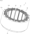
- THE figures 6 to 8 represent a first example of embodiment according to the electrical diagram of the figure 1 and some picture 3 in which the stator 3 comprises a first connection frame 7 placed on the internal part 31b of the stator body 31 and configured to connect a first end of the coils 33 of the different phases u, v, w to each other to form the star connection.
- the first connection frame 7 comprises five portions denoted respectively 7a, 7b, 7c, 7d and 7e each connecting three coils 33 respectively associated with the three phases u, v, w.
- the three coils 33 respectively associated with the three phases u, v, w can be arranged adjacently on the stator body 31 as on the figure 6 .
- the stator 3 also comprises second connection frames 9 arranged on the external part 31a of the stator body 31 and configured to connect the second end of the coils 33 according to the electrical diagram of the figure 4 (parallel connection of the various coils 33 associated with a phase u, vw).
- the second connection frames 9 are also configured to allow electrical connections to the outside of the stator 3, in particular for the supply of the different phases u, v, w, for example via additional connectors arranged on the second connection frames 9
- the stator 3 comprises three second connection frames 9 denoted respectively 9a, 9b and 9c arranged on one side of the stator 3 concentrically around the coils 33.
- the second connection frames 9 are separated from each other by electrically non-conductive walls 11 also arranged concentrically with the second connection frames 9.
- These electrically non-conductive walls 11 are for example made of plastic material and can be molded on the stator body 31 and may in particular come in one piece with the electrical insulating element 14.
- the non-conductive walls 11 have a higher than the second lead frames 9 and locally include recesses of material 110 in their part protruding from the second lead frames 9 to allow the connections between the coils 33 and the second lead frames 9.
- the recesses of material 110 of the different walls not electrically conductive conductors 11 are arranged facing each other and facing the coils 33.
- the number of material withdrawals 110 corresponds for example to the number of coils 33, that is fifteen in the example of the figure 6 .
- the second connection frames 9 comprise connectors 13 configured to project axially outwards from the stator 3 and extend opposite the recesses of material 110 of the electrically non-conductive walls 11.
- the second end of the coils 33 is therefore configured to extend radially through the recesses of material 110 as far as the connector of one of the second connection frames 9 arranged opposite the corresponding coil 33.
- the first 7 and second 9 connection frames are thus arranged on a first radial side of the stator body 31 and adjacent to the stator body 31.
- the axial height of the first 7 and second 9 connection frames and the electrically non-conductive walls 11 is limited to the maximum so as to limit the axial dimension of the stator 3. 9 concentrically make it possible to limit the outer diameter of the stator 3.
- stator 3 The axial and radial size of the stator 3 is therefore reduced compared to the electric motors of the state of the art having an equivalent power.
- the winding of the coils 33 on the teeth 35 can be carried out starting from the side of the part internal 31b of the stator body 31 which makes it possible to limit the distance between the first connection frame 7 and the first end of the coil 33 and also to limit the size of the coils 33 and therefore of the stator 3.
- a holding stud 15 can be arranged on the internal end of the teeth 35 (located on the side of the internal part 31b of the stator body 31) to hold the first end of the wire of the coil 35, in particular during winding turns to form the coil 35.
- This holding pad 15 can be a temporary stud configured to be removed when connecting the first end of the coil 35 to the first connection frame 7.
- the holding pad 15 is for example arranged on the electrical insulating element 14 and can be integral with said electrical insulating element 14.
- the stator 3 comprises first connection frames denoted respectively 7a, 7b and 7c arranged on the internal part 31b of the stator body 31 and configured to connect a first end of the coils 33 according to the electrical diagram of the figure 4 (parallel connection of the various coils 33 associated with a phase u, v, w).
- the first connection frames 7 are also configured to allow electrical connections to the outside of the stator 3, in particular for the supply of the various phases u, v, w, for example via additional connectors 17.
- the first connection frames 7 have for example a configuration similar to the second connection frames 9 described in the first embodiment, that is to say arranged concentrically with respect to each other and separated by electrically non-conductive walls 11'.
- the electrically non-conductive walls 11' also include recesses of material 110 arranged opposite each other and the first connection frames 7 comprise connectors 13' extending axially opposite the recesses of material 110 to allow connection with the first end of the coil 33 arranged opposite the recesses of material 110.
- first connection frames 7 and the electrically non-conductive walls 11' can be arranged on a module 19 configured to be fixed on the stator body 31.
- the module 19 is for example made of plastic and comprises radial lugs 190 on its periphery, said radial lugs 190 being configured to be positioned between the teeth 35 of the stator body 31 to ensure the fixing of the module 19 on the stator body 31.
- the electrically non-conductive walls 11' can come in one piece with the module 19 and the first connection frames 7 are assembled on the module 19.
- the first connection frames 7 are for example positioned in slots made between the electrically non-conductive walls 11'.
- the stator 3 also includes a second connection frame 9 (visible on the figure 9 ) disposed on the outer part 31a of the stator body 31 and configured to connect the second end of the coils 33 of the different phases u, v, w together to form the star connection.
- the second connection frame 9 comprises for example five portions each connecting three coils 33 respectively associated with the three phases u, v, w.
- these connections can be made via one or more second connection frame(s) 9 forming a complete ring on which some or all of the coils are connected according to the desired electrical diagram.
- the three coils 33 respectively associated with the three phases u, v, w can be arranged adjacently on the stator body 31.
- the second connection frame 9 is for example arranged on an electrical insulating element 14 made of plastic material which can be overmolded on the stator body 31.
- the first (s) 7 and second (s) 9 connection frames are made of metal, for example aluminum, brass, copper or iron.
- the teeth 35 of the stator body 31 may be separate teeth as shown in Fig. picture 3 .
- the stator 3 only comprises first connection frames 7 arranged on the internal part 31b of the stator 3 and configured to provide all of the electrical connections between the coils 33.
- the first connection frames 7 can be arranged on a module such as the module 19 described above.
- the present invention also relates to an electric motor 1 comprising a stator 3 as described according to one of the preceding embodiments.
- the electric motor 1 also includes a rotor 5 (visible on the figure 1 And 9 ) configured to be positioned inside the stator 3, that is to say in the center of the stator body 31 and the coils 33.
- the electric motor 1 is for example a brushless three-phase electric motor and comprises for example 10 or 14 poles (in the case of an electric motor 1 with 15 coils) but other types of electric motors 1 having in particular a different number of poles can also be used.
- the poles are for example made by permanent magnets arranged on the rotor 5.
- the present invention also relates to a method of manufacturing a stator 3 comprising a stator body 31 comprising a plurality of teeth 33 extending between an external part 31a and an internal part 31b of the stator 3, for example a stator 3 according to the first exemplary embodiment described above.
- FIG 11 represents a flowchart of the steps of the manufacturing method of such a stator 3 according to the first embodiment presented on the figure 1 And 6 wherein the teeth 35 are integral with the stator body 31.
- the first step 101 concerns the positioning of the electrical insulating element 14 on the stator body 31.
- the electrical insulating element 14 is for example made of plastic material and is molded onto the stator body 31.
- the insulating element electric 14 includes the electrically non-conductive walls 11.
- the second step 102 concerns the positioning of the first 7 and second 9 connection frames on the electrical insulating element 14.
- the first connection frames 7 being positioned on the external part 31a of the stator body 31 and the second connection frame 9 being positioned on the internal part 31b of the stator body 31.
- the fixing frames are held on the electrical insulating element 14 by form complementarity or by stresses, the connection frame being able to be subjected to plastic deformation by holding studs arranged on the electrical insulating element 14.
- the third step 103 is an optional step and concerns the positioning of the first end of the coil 33 in a holding pad 15 configured to hold the end of the spool 33 in position while winding the spool.
- the holding pad 15 can be formed on the electrical insulating element 14.
- the fourth step 104 concerns the winding of the coils 33 on the teeth 35 of the stator body 31.
- the teeth 35 are made in one piece with the stator body 31 and the winding is made starting from the internal side 31b of the stator body 31 as shown in the figure 7 And 8 .
- the winding comprises a plurality of turns extending from the inner part 31b to the outer part 31a of the stator body 31. Different layers of turns can be formed, for example three layers of turns by winding a new layer of turns over the previous layer. The turns are retained by the rim formed by the end of the teeth 35, the section of which has a T-shape. In the case of three layers of turns, the winding ends on the outer side 31a of the stator body 31.
- the winding can be carried out starting from the external side.
- the winding can comprise a number of layers of turns other than three.
- the winding is made in such a way as to make maximum use of the space available around the teeth 35 while allowing the windings of the adjacent coils 33 to be made.
- the winding is for example produced by a robot configured to come and wind the turns around the teeth 35.
- the windings around the various teeth 35 are for example produced one after the other, the windings all being identical.
- the fifth step 105 relates to the connections between the ends of the coils 33 and the first connection frame 7 on the one hand and between the ends of the coils 33 and the second connection frames 9 on the other hand.
- the connection is for example made by soldering or via connectors arranged on the connection frames 7, 9 and configured to hold the winding wire and to ensure the electrical connection between the winding wire and the connection frames 7, 9 or by any other means known to those skilled in the art.
- the sixth step 106 is an optional step and relates to the removal of the holding stud 15 used during step 103 when this holding stud 15 is a temporary and removable stud.
- step 106 can for example be carried out before step 105.
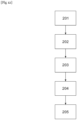
- FIG 12 represents a flowchart of the steps of the method for manufacturing a stator as described previously according to the second embodiment presented on the figure 9 And 10 .
- the first step 201 relates to the positioning of the electrical insulating element 14 on the stator body 31.
- the electrical insulating element 14 is for example made of plastic material and is molded onto the stator body 31. In the present case, the electrical insulating element 14 extends over the outer part 31a of the stator body 31.
- the second step 202 relates to the winding of the coils on the teeth of the stator body 31.
- the winding is carried out starting from the internal side of the stator.
- the winding includes a plurality of turns extending between the two ends of the tooth. Different layers of turns can be formed, for example three layers of turns by winding a new layer of turns over the previous layer. The turns are retained by the rim formed by the end of the teeth 35, the section of which has a T-shape. In the case of three layers of turns, the winding ends on the internal side 31b of the stator body 31. Alternatively, the winding may terminate at other locations.
- the winding can comprise a number of layers of turns other than three.
- the winding is carried out in such a way as to make maximum use of the space available around the teeth 35.
- the winding is for example carried out by a robot configured to come and wind the turns around the teeth.
- the windings are all identical. Holding pads, removable or not, can be provided on the electrical insulating element 14 to hold the end of the winding wire.
- the third step 203 concerns the positioning of the second connection frame 9 on the electrical insulating element 14 at the level of the external part 31a of the stator body 31.
- the fourth step 204 concerns the positioning of the module 19 comprising the first connection frames on the stator body 31.
- the positioning is carried out by inserting the radial tabs 190 of the module 19 between the coils 33.
- the fifth step 205 relates to the connections between the ends of the coils 33 and the connection frames 7, 9.
- the connection is for example made by soldering or via connectors arranged on the connection frames 7, 9 and configured to hold the wire of winding and to ensure the electrical connection between the connection frames 7, 9 and the winding wire or by any other means known to those skilled in the art.
- the stator 3 may comprise separate teeth as shown in the picture 3 .
- the coils 33 are wound on the teeth 35 first, then the teeth 35 are placed on the stator body 31.
- the other steps can be similar to the steps presented previously.
- the arrangement of the connection frames both on the internal side 31a and the external side 31b of the stator body 31 and therefore of the stator 3 makes it possible to obtain an electric motor 1 that is compact axially and radially, which makes it possible to integrate it easily, especially in electric bicycles.
- the manufacture of such electric motors remains simple and therefore allows large-scale manufacture.
Landscapes
- Engineering & Computer Science (AREA)
- Power Engineering (AREA)
- Insulation, Fastening Of Motor, Generator Windings (AREA)
- Manufacture Of Motors, Generators (AREA)
- Iron Core Of Rotating Electric Machines (AREA)
- Windings For Motors And Generators (AREA)
Applications Claiming Priority (1)
| Application Number | Priority Date | Filing Date | Title |
|---|---|---|---|
| FR2110268A FR3127651B1 (fr) | 2021-09-29 | 2021-09-29 | Moteur électrique, stator pour moteur électrique et procédé de fabrication associé |
Publications (1)
| Publication Number | Publication Date |
|---|---|
| EP4160880A1 true EP4160880A1 (de) | 2023-04-05 |
Family
ID=78827813
Family Applications (1)
| Application Number | Title | Priority Date | Filing Date |
|---|---|---|---|
| EP22195530.5A Pending EP4160880A1 (de) | 2021-09-29 | 2022-09-14 | Elektromotor, stator für einen elektromotor und zugehöriges herstellungsverfahren |
Country Status (5)
| Country | Link |
|---|---|
| US (1) | US20230101491A1 (de) |
| EP (1) | EP4160880A1 (de) |
| JP (1) | JP7676346B2 (de) |
| CN (1) | CN115882620A (de) |
| FR (1) | FR3127651B1 (de) |
Citations (2)
| Publication number | Priority date | Publication date | Assignee | Title |
|---|---|---|---|---|
| DE112018001800T5 (de) * | 2017-03-31 | 2019-12-12 | Nidec Corporation | Sammelschieneneinheit und Motor, der diese aufweist |
| US20210028666A1 (en) * | 2019-07-26 | 2021-01-28 | Johnson Electric International AG | Brushless motor, stator and method of manufacturing the same |
Family Cites Families (6)
| Publication number | Priority date | Publication date | Assignee | Title |
|---|---|---|---|---|
| JP5176283B2 (ja) * | 2006-03-30 | 2013-04-03 | 日産自動車株式会社 | 回転電機のバスバー絶縁構造 |
| JP6009937B2 (ja) * | 2012-12-28 | 2016-10-19 | 株式会社Top | 回転機 |
| JP2016185034A (ja) * | 2015-03-26 | 2016-10-20 | 株式会社東芝 | 回転電機 |
| FR3058280B1 (fr) * | 2016-11-03 | 2020-07-31 | Valeo Equip Electr Moteur | Stator de machine electrique tournante muni d'un interconnecteur a configuration amelioree |
| JP6745838B2 (ja) * | 2018-06-06 | 2020-08-26 | 三菱電機株式会社 | 回転電機及びその製造方法 |
| DE102019210146B4 (de) * | 2019-07-10 | 2021-04-29 | Bühler Motor GmbH | Verfahren zur Herstellung eines Stator eines Elektromotors |
-
2021
- 2021-09-29 FR FR2110268A patent/FR3127651B1/fr active Active
-
2022
- 2022-08-29 US US17/897,373 patent/US20230101491A1/en active Pending
- 2022-09-14 EP EP22195530.5A patent/EP4160880A1/de active Pending
- 2022-09-22 CN CN202211159172.4A patent/CN115882620A/zh active Pending
- 2022-09-28 JP JP2022155318A patent/JP7676346B2/ja active Active
Patent Citations (2)
| Publication number | Priority date | Publication date | Assignee | Title |
|---|---|---|---|---|
| DE112018001800T5 (de) * | 2017-03-31 | 2019-12-12 | Nidec Corporation | Sammelschieneneinheit und Motor, der diese aufweist |
| US20210028666A1 (en) * | 2019-07-26 | 2021-01-28 | Johnson Electric International AG | Brushless motor, stator and method of manufacturing the same |
Also Published As
| Publication number | Publication date |
|---|---|
| FR3127651A1 (fr) | 2023-03-31 |
| FR3127651B1 (fr) | 2024-08-30 |
| JP7676346B2 (ja) | 2025-05-14 |
| CN115882620A (zh) | 2023-03-31 |
| US20230101491A1 (en) | 2023-03-30 |
| JP2023055664A (ja) | 2023-04-18 |
Similar Documents
| Publication | Publication Date | Title |
|---|---|---|
| EP2677634B1 (de) | Zwischenverbinder für einen Stator einer elektrischen Maschine und Stator mit einem derartigen Zwischenverbinder | |
| FR2852461A1 (fr) | Stator pour machine dynamo-electriques | |
| FR2959363A1 (fr) | Machine dynamo-electrique | |
| FR2868620A1 (fr) | Induit polyphase pour machine electrique tournante, notamment un alternateur pour vehicule automobile, et son procede de fabrication | |
| EP3166210B1 (de) | Elektrisch umlaufende maschine, die mit einem stator ausgestattet ist | |
| EP3602755A1 (de) | Elektrische drehmaschine mit verbesserter anordnung | |
| FR2999821A1 (fr) | Rotor a griffes dote d'un isolant d'un bobinage d'excitation et une machine electrique tournante equipee d'un tel rotor | |
| WO2015145007A2 (fr) | Élément d'interconnexion pour le branchement des bobines du stator | |
| EP2860847B1 (de) | Bewickelter Stator mit optimierter Nutenfüllung, und entsprechende elektrische Maschine | |
| EP4160880A1 (de) | Elektromotor, stator für einen elektromotor und zugehöriges herstellungsverfahren | |
| FR2918512A1 (fr) | Machine electrique tournante conformee pour pouvoir fonctionner sous au moins deux tensions electriques differentes | |
| WO2008043926A1 (fr) | Rotor a griffes muni d'elements ferromagnetiques interpolaires de largeur optimisee et machine tournante equipee d'un tel rotor | |
| EP4125182A1 (de) | Elektromotor, stator für einen elektromotor und zugehöriges herstellungsverfahren | |
| WO2023052605A1 (fr) | Bobine pour stator de moteur électrique, stator et procédé de fabrication | |
| EP3535833A1 (de) | Stator einer elektrischen drehmaschine mit orthozyklisch gewickelten spulen | |
| FR3076406A1 (fr) | Rotor de machine electrique tournante et procede de fabrication associe | |
| FR3127653A1 (fr) | Stator pour moteur électrique et moteur électrique associé | |
| WO2023052601A1 (fr) | Bobine pour stator de moteur électrique, stator et procédé de fabrication | |
| FR3093387A1 (fr) | Dispositif de connexion pour stator | |
| FR3127658A1 (fr) | Bobine pour stator de moteur électrique, stator associé et procédé de fabrication associé | |
| EP3535834A1 (de) | Stator einer elektrischen drehmaschine mit einer verbindung mit verbesserter konfiguration | |
| FR3126567A1 (fr) | Procédé de bobinage d'un stator de machine électrique tournante à multi-encoches par pôle et par phase | |
| WO2023052612A1 (fr) | Stator pour moteur électrique triphasé et moteur électrique associé | |
| FR3058283A1 (fr) | Stator de machine electrique tournante muni d'un interconnecteur a positionnement optimum | |
| WO2022128900A1 (fr) | Dispositif d'interconnexion pour une machine electrique tournante |
Legal Events
| Date | Code | Title | Description |
|---|---|---|---|
| PUAI | Public reference made under article 153(3) epc to a published international application that has entered the european phase |
Free format text: ORIGINAL CODE: 0009012 |
|
| STAA | Information on the status of an ep patent application or granted ep patent |
Free format text: STATUS: THE APPLICATION HAS BEEN PUBLISHED |
|
| AK | Designated contracting states |
Kind code of ref document: A1 Designated state(s): AL AT BE BG CH CY CZ DE DK EE ES FI FR GB GR HR HU IE IS IT LI LT LU LV MC MK MT NL NO PL PT RO RS SE SI SK SM TR |
|
| STAA | Information on the status of an ep patent application or granted ep patent |
Free format text: STATUS: REQUEST FOR EXAMINATION WAS MADE |
|
| 17P | Request for examination filed |
Effective date: 20231004 |
|
| RBV | Designated contracting states (corrected) |
Designated state(s): AL AT BE BG CH CY CZ DE DK EE ES FI FR GB GR HR HU IE IS IT LI LT LU LV MC MK MT NL NO PL PT RO RS SE SI SK SM TR |
|
| STAA | Information on the status of an ep patent application or granted ep patent |
Free format text: STATUS: EXAMINATION IS IN PROGRESS |
|
| 17Q | First examination report despatched |
Effective date: 20250408 |