EP4160975A1 - Verfahren und vorrichtung zur messung von interferenz- oder signalempfangsleistung - Google Patents
Verfahren und vorrichtung zur messung von interferenz- oder signalempfangsleistung Download PDFInfo
- Publication number
- EP4160975A1 EP4160975A1 EP22209791.7A EP22209791A EP4160975A1 EP 4160975 A1 EP4160975 A1 EP 4160975A1 EP 22209791 A EP22209791 A EP 22209791A EP 4160975 A1 EP4160975 A1 EP 4160975A1
- Authority
- EP
- European Patent Office
- Prior art keywords
- value
- rsrp
- terminal device
- reported
- srs
- Prior art date
- Legal status (The legal status is an assumption and is not a legal conclusion. Google has not performed a legal analysis and makes no representation as to the accuracy of the status listed.)
- Granted
Links
Images



Classifications
-
- H—ELECTRICITY
- H04—ELECTRIC COMMUNICATION TECHNIQUE
- H04L—TRANSMISSION OF DIGITAL INFORMATION, e.g. TELEGRAPHIC COMMUNICATION
- H04L5/00—Arrangements affording multiple use of the transmission path
- H04L5/003—Arrangements for allocating sub-channels of the transmission path
- H04L5/0048—Allocation of pilot signals, i.e. of signals known to the receiver
- H04L5/0051—Allocation of pilot signals, i.e. of signals known to the receiver of dedicated pilots, i.e. pilots destined for a single user or terminal
-
- H—ELECTRICITY
- H04—ELECTRIC COMMUNICATION TECHNIQUE
- H04B—TRANSMISSION
- H04B17/00—Monitoring; Testing
- H04B17/30—Monitoring; Testing of propagation channels
- H04B17/309—Measuring or estimating channel quality parameters
- H04B17/318—Received signal strength
- H04B17/327—Received signal code power [RSCP]
-
- H—ELECTRICITY
- H04—ELECTRIC COMMUNICATION TECHNIQUE
- H04B—TRANSMISSION
- H04B17/00—Monitoring; Testing
- H04B17/30—Monitoring; Testing of propagation channels
- H04B17/309—Measuring or estimating channel quality parameters
- H04B17/336—Signal-to-interference ratio [SIR] or carrier-to-interference ratio [CIR]
-
- H—ELECTRICITY
- H04—ELECTRIC COMMUNICATION TECHNIQUE
- H04L—TRANSMISSION OF DIGITAL INFORMATION, e.g. TELEGRAPHIC COMMUNICATION
- H04L25/00—Baseband systems
- H04L25/02—Details ; arrangements for supplying electrical power along data transmission lines
- H04L25/0202—Channel estimation
- H04L25/0224—Channel estimation using sounding signals
- H04L25/0226—Channel estimation using sounding signals sounding signals per se
-
- H—ELECTRICITY
- H04—ELECTRIC COMMUNICATION TECHNIQUE
- H04L—TRANSMISSION OF DIGITAL INFORMATION, e.g. TELEGRAPHIC COMMUNICATION
- H04L43/00—Arrangements for monitoring or testing data switching networks
- H04L43/50—Testing arrangements
-
- H—ELECTRICITY
- H04—ELECTRIC COMMUNICATION TECHNIQUE
- H04L—TRANSMISSION OF DIGITAL INFORMATION, e.g. TELEGRAPHIC COMMUNICATION
- H04L5/00—Arrangements affording multiple use of the transmission path
- H04L5/003—Arrangements for allocating sub-channels of the transmission path
- H04L5/0048—Allocation of pilot signals, i.e. of signals known to the receiver
-
- H—ELECTRICITY
- H04—ELECTRIC COMMUNICATION TECHNIQUE
- H04L—TRANSMISSION OF DIGITAL INFORMATION, e.g. TELEGRAPHIC COMMUNICATION
- H04L5/00—Arrangements affording multiple use of the transmission path
- H04L5/003—Arrangements for allocating sub-channels of the transmission path
- H04L5/0058—Allocation criteria
- H04L5/0073—Allocation arrangements that take into account other cell interferences
-
- H—ELECTRICITY
- H04—ELECTRIC COMMUNICATION TECHNIQUE
- H04W—WIRELESS COMMUNICATION NETWORKS
- H04W24/00—Supervisory, monitoring or testing arrangements
- H04W24/06—Testing, supervising or monitoring using simulated traffic
-
- H—ELECTRICITY
- H04—ELECTRIC COMMUNICATION TECHNIQUE
- H04W—WIRELESS COMMUNICATION NETWORKS
- H04W24/00—Supervisory, monitoring or testing arrangements
- H04W24/08—Testing, supervising or monitoring using real traffic
-
- H—ELECTRICITY
- H04—ELECTRIC COMMUNICATION TECHNIQUE
- H04W—WIRELESS COMMUNICATION NETWORKS
- H04W24/00—Supervisory, monitoring or testing arrangements
- H04W24/10—Scheduling measurement reports ; Arrangements for measurement reports
-
- Y—GENERAL TAGGING OF NEW TECHNOLOGICAL DEVELOPMENTS; GENERAL TAGGING OF CROSS-SECTIONAL TECHNOLOGIES SPANNING OVER SEVERAL SECTIONS OF THE IPC; TECHNICAL SUBJECTS COVERED BY FORMER USPC CROSS-REFERENCE ART COLLECTIONS [XRACs] AND DIGESTS
- Y02—TECHNOLOGIES OR APPLICATIONS FOR MITIGATION OR ADAPTATION AGAINST CLIMATE CHANGE
- Y02D—CLIMATE CHANGE MITIGATION TECHNOLOGIES IN INFORMATION AND COMMUNICATION TECHNOLOGIES [ICT], I.E. INFORMATION AND COMMUNICATION TECHNOLOGIES AIMING AT THE REDUCTION OF THEIR OWN ENERGY USE
- Y02D30/00—Reducing energy consumption in communication networks
- Y02D30/70—Reducing energy consumption in communication networks in wireless communication networks
Definitions
- the present application relates to the field of communication, and more particularly, to a method and a device for interference or signal received power measurement.
- New radio (NR) systems have higher requirements for communication quality.
- terminal devices usually interfered by other communication devices during communication, resulting in the decrease in communication quality.
- another terminal device in an adjacent cell may be in uplink communication, and the terminal device in downlink communication may be interfered by uplink signals sent by the terminal device in uplink communication.
- the terminal devices In order to control interference caused by other communication devices, the terminal devices need to measure interference or signal received power. Therefore, how to measure the interference or signal received power efficiently has become a problem to be solved urgently.
- Embodiments of the present application provide a method and device for interference or signal received power measurement, so as to measure the interference or signal received power efficiently.
- a method for interference or signal received power measurement which includes: a terminal device measures a sounding reference signal (SRS) resource to obtain a reference signal received power (RSRP) value corresponding to at least one SRS resource; the terminal device determines a to-be-reported value based on the at least one RSRP value corresponding to the at least one SRS resource; and the terminal device reports the to-be-reported value to a network device.
- SRS sounding reference signal
- RSRP reference signal received power
- a method for interference or signal received power measurement which includes: a network device receives a to-be-reported value sent by a terminal device; the network device determines at least one reference signal received power (RSRP) value corresponding to at least one sounding reference signal (SRS) resource based on the to-be-reported value, at least one RSRP value being obtained based on measurement on the at least one SRS resource; and the network device communicates with the terminal device based on the at least one RSRP value.
- RSRP reference signal received power
- SRS sounding reference signal
- a terminal device for performing the method according to the first aspect described above or any implementation thereof.
- the terminal device includes functional modules for performing the method according to the first aspect described above or any implementation thereof.
- a network device for performing the method according to the second aspect described above or any implementation thereof.
- the network device includes functional modules for performing the method according to the second aspect described above or any implementation thereof.
- a terminal device including a processor and a memory.
- the memory is configured to store a computer program
- the processor is configured to call and run the computer program stored in the memory to perform the method according to the first aspect described above or any implementations thereof.
- a network device including a processor and a memory.
- the memory is configured to store a computer program
- the processor is configured to call and run the computer program stored in the memory to perform the method according to the second aspect described above or any implementations thereof.
- a chip for implementing the method according to any one of the first and third aspects described above or any implementations thereof.
- the chip includes a processor configured call and run a computer program from a memory to enable a device having the chip installed thereon to perform the method according to any one of the first and second aspects described above or any implementations thereof.
- a computer readable storage medium for storing a computer program that enables a computer to perform the method according to any one of the first and second aspects described above or any implementations thereof.
- a computer program product including computer program instructions that enable a computer to perform the method according to any one of the first and second aspects described above or any implementations thereof.
- a computer program which, when running on a computer, enables the computer to perform the method according to any one of the first and second aspects described above or any implementations thereof.
- the terminal device measures the SRS resources, and then determines the to-be-reported value based on measurement results obtained by measuring the SRS resources. Since there are multiple aggressors or signals that cause interference to the terminal device, the terminal device can identify different aggressors or signals by measuring the SRS resources. Therefore, the terminal device can identify the aggressor or signals that cause interference to itself, by measuring the SRS resources, so that the measurement can be more efficient.
- GSM Global System of Mobile Communication
- CDMA Code Division Multiple Access
- WCDMA Wideband Code Division Multiple Access
- GPRS General Packet Radio Service
- LTE Long Term Evolution
- LTE-A Advanced Long Term Evolution
- NR New Radio
- UMTS Universal Mobile Telecommunication System
- WLAN Wireless Local Area Networks
- WiFi Wireless Fidelity
- a mobile communication system will not only support traditional communication, but also support, for example, device to device (D2D) communication, machine to machine (M2M) communication, machine type communication (MTC), vehicle to vehicle (V2V) communication, and the embodiments of the present application may also be applied to these communication systems.
- D2D device to device
- M2M machine to machine
- MTC machine type communication
- V2V vehicle to vehicle
- a communication system in the embodiments of the present application may be applied to a carrier aggregation (CA) scenario, a dual connectivity (DC) scenario, or a standalone (SA) scenario.
- CA carrier aggregation
- DC dual connectivity
- SA standalone
- the communication system 100 may include a network device 110, which may be a device that communicates with terminal devices 120 (or referred to as communication terminals, or terminals).
- the network device 110 may provide communication coverage for a specific geographical area, and may communicate with terminal devices located within the coverage area.
- the network device 110 may be a base transceiver station (BTS) in a GSM system or CDMA system, a NodeB (NB) in a WCDMA system, an Evolutional Node B (eNB or eNodeB) in an LTE system, or a radio controller in a cloud radio access network (CRAN), or the network device may be a mobile switching center, a relay station, an access point, a vehicle-mounted device, a wearable device, a hub, a switch, a bridge, a router, a network side device in a 5G network, or a network device in a future evolved public land mobile network (PLMN).
- BTS base transceiver station
- NB NodeB
- eNB or eNodeB Evolutional Node B
- CRAN cloud radio access network
- PLMN future evolved public land mobile network
- the communication system 100 further includes at least one terminal device 120 located within the coverage area of the network device 110.
- the "terminal device” as used herein includes, but is not limited to, a device configured to receive/send communication signals through a connection via a wired circuit, for example, via a public switched telephone network (PSTN), a digital subscriber line (DSL), a digital cable, a direct cable, and/or another data connection/network, and/or via a wireless interface, for instance, for a cellular network, a wireless local area network (WLAN), a digital television network such as a digital video broadcasting-handheld (DVB-H) network, a satellite network, and an amplitude modulation - frequency modulation (AM-FM) broadcast transmitter, and/or another terminal device; and/or an Internet of Things (IoT) device.
- PSTN public switched telephone network
- DSL digital subscriber line
- AM-FM amplitude modulation - frequency modulation
- IoT Internet of Things
- a terminal device configured to communicate via a wireless interface may be referred to as "a wireless communication terminal", “a wireless terminal” or “a mobile terminal".
- the mobile terminal include, but are not limited to, a satellite or cellular phone; a personal communications system (PCS) terminal capable of combining a cellular radio phone, data processing, facsimile, and data communication capabilities; a personal digital assistant (PDA) that may include a radio phone, a pager, internet/intranet access, a Web browser, a memo pad, a calendar, a Global Positioning System (GPS) receiver; and a conventional laptop and/or palmtop receiver or other electronic devices including a radio phone transceiver.
- PCS personal communications system
- PDA personal digital assistant
- GPS Global Positioning System
- the terminal device may refer to an access terminal, a user equipment (UE), a subscriber unit, a subscriber station, a mobile site, a mobile station, a remote station, a remote terminal, a mobile device, a user terminal, a terminal, a wireless communication device, a user agent, or a user apparatus.
- UE user equipment
- the access terminal may be a cellular phone, a cordless phone, a Session Initiation Protocol (SIP) phone, a Wireless Local Loop (WLL) station, a Personal Digital Assistant (PDA), a handheld device with a wireless communication function, a computing device, or other processing devices connected to a wireless modem, a vehicle-mounted device, a wearable device, a terminal device in a 5G network, or a terminal device in a future evolved Public Land Mobile Network (PLMN).
- SIP Session Initiation Protocol
- WLL Wireless Local Loop
- PDA Personal Digital Assistant
- PLMN Public Land Mobile Network
- D2D communication may be performed between the terminal devices 120.
- FIG. 1 illustrates exemplarily one network device and two terminal devices.
- the communication system 100 may include multiple network devices, and other quantities of terminal devices may be included within the coverage area of each network device, which is not limited in the embodiments of the present application.
- the communication system 100 may include other network entities, such as a network controller and a mobile management entity, which is not limited in the embodiments of the present application.
- a device with a communication function in a network/system in the embodiments of the present application may be referred to as a communication device.
- the communication device may include a network device 110 and terminal devices 120 which have communication functions, and the network device 110 and the terminal devices 120 may be the specific devices described above, and will not be described repeatedly herein.
- the communication device may also include other devices in the communication system 100, such as other network entities, such as network controllers and mobile management entities, which is not limited in the embodiments of the present application.
- system and “network” are often used interchangeably herein.
- the term “and/or” herein describes an association relationship between associated objects only, indicating that there may be three relationships, for example, A and/or B may indicate three cases: A alone, both A and B, and B alone.
- the symbol “/” herein generally indicates that there is a “or” relationship between the associated objects before and after "/”.
- Different services or applications (APPs) of terminal devices may have different requirements for an uplink data rate and a downlink data rate.
- the downlink data rate is generally higher than the uplink data rate.
- the uplink data rate of some services/APPs may be higher than the downlink data rate.
- the uplink data rate is higher than the downlink data rate.
- different operations may also tend to have different requirements for the uplink and downlink data rates. For example, when videos are uploaded to share, the uplink data rate may be higher than the downlink data rate, while when the videos shared by friends are watched, the downlink data rate may be higher than the uplink data rate.
- a wireless network maintains fixed or semi-static uplink and downlink resource allocation (e.g., fixed uplink and downlink time slot configuration in an LTE/NR system), optimal matching for service transmission may not be achieved in a short period of time, resulting in inefficient utilization of resources and a problem that the experience of terminal devices cannot be further improved.
- fixed or semi-static uplink and downlink resource allocation e.g., fixed uplink and downlink time slot configuration in an LTE/NR system
- a method of performing dynamical adjustment in uplink and downlink transmission directions may be used. For example, if the amount of downlink data of the current cell or a terminal device increases, a network device may use more resources for downlink transmission (e.g., use more time slots for downlink transmission).
- a flexible time slot format is proposed in an NR system.
- the time slot format includes information that how many downlink symbols, how many flexible symbols and how many uplink symbols are included in one time slot.
- Configurations of some time slot formats supported in the current NR protocol may be shown in Table 1.
- Table 1 one row represents one time slot, and it can be seen that each time slot has 14 symbols.
- “D” in Table 1 represents a downlink symbol
- "U” represents an uplink symbol
- "F” represents a flexible symbol.
- time slot format 0 indicates that 14 symbols in a time slot are all downlink symbols
- time slot format 1 indicates that 14 symbols in a time slot are all uplink symbols
- time slot format 20 indicates that first 2 symbols in a time slot are configured as downlink symbols, last one symbol is configured as an uplink symbol, and middle 11 symbols are configured as flexible symbols.
- time slot formats are modified relatively dynamically in a cell, or the network device modifies its corresponding slot formats for one or some terminal devices, additional interference may be caused (with respect to uplink and downlink configured to be static).
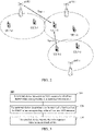
- base station 3 may configure more uplink resources (e.g., more time slots are configured as full uplink symbols or more symbols in some time slots are configured as uplink) for transmission of UE 3-2. If uplink and downlink transmissions of UE 1-2 and UE 3-2 are different, additional interference may be caused, for example, type 2 interference shown in the figure. That is, when UE 1-2 receives the downlink data transmission, it may be possible that the UE 1-2 is interfered by uplink signals sent by its adjacent UE 3-2.
- more uplink resources e.g., more time slots are configured as full uplink symbols or more symbols in some time slots are configured as uplink
- additional interference may be caused, for example, type 2 interference shown in the figure. That is, when UE 1-2 receives the downlink data transmission, it may be possible that the UE 1-2 is interfered by uplink signals sent by its adjacent UE 3-2.
- the type 2 interference may also be caused.
- all symbols in a time slot are flexible symbols (e.g., time slot format 2 in Table 1)
- gNB1 may use this time slot for downlink transmission of UE 1-2
- gNB3 may use this time slot for uplink transmission of UE 3-2, in this case, the type 2 interference described above will also be caused.
- an embodiment of the present application provides a method for interference or signal measurement.
- FIG. 3 is a schematic flow chart of a method 300 for interference or signal measurement in accordance with an embodiment of the present application.
- CLI cross-link interference
- CLI may be interference caused by uplink sending of at least one terminal device to downlink reception of its adjacent terminal devices.
- CLI measurement is not limited to be between terminals only, it may also be used in other similar situations, such as between network devices.
- SRS-RSRP sounding reference signal-reference signal received power
- RSSI received signal strength indicator
- the SRS-RSRP is an SRS-based RSRP, that is, an RSRP value obtained by measuring an SRS.
- a network device may configure an SRS for SRS-RSRP measurement of a terminal device, and information configured by the network device for the terminal device to measure an SRS may include, but is not limited to: time-frequency resource(s), SRS sequence(s), cyclic shift(s), and measurement periodicity.
- the network device may configure a set of time-frequency resources for RSSI measurement of the terminal device, wherein the configuration may include an indication at a symbol level and an indication at a physical resource block (PRB) level.
- PRB physical resource block
- a measurement variable is the RSSI
- the measurement of the terminal device is simpler, but different aggressors cannot be distinguished; or in order to identify the aggressors, the signaling overhead is too high.
- the method in the embodiment of the present application may also be applied to other scenarios, for example, interference of other network devices to the terminal device, interference between adjacent cells, or type 1 interference mentioned above.
- the method 300 may include at least portion of the following contents.
- a terminal device measures SRS resources to obtain at least one RSRP value corresponding to at least one SRS resource.
- the terminal device determines a to-be-reported value based on the at least one RSRP value corresponding to the at least one SRS resource.
- the terminal device reports the to-be-reported value to the network device.
- the way of reporting the to-be-reported value by the terminal device corresponds to the way of determining the to-be-reported value by the network device, and these two ways will be described below in combination with each other.
- the RSRP values corresponding to the SRS resources may be understood as RSRP values obtained by measuring the SRS resources by the terminal device.
- the terminal device may obtain at least one reference signal receiving quality (RSRQ) value or at least one signal to interference plus noise ratio (SINR) value in addition to the at least one RSRP value obtained by measuring the SRS resources, that is, the terminal device may measure the SRS resources to obtain at least one of the at least one RSRQ value, RSRP value and SINR value.
- RSRQ reference signal receiving quality
- SINR signal to interference plus noise ratio
- the RSRP represents the signal received power, and the RSRP can reflect a signal strength to a certain extent; the RSRQ represents signal reception quality, and the RSRQ can reflect signal transmission quality to a certain extent.
- the SINR refers to a ratio of the strength of the received useful signal to the strength of the received interference signal (noise and interference), which can be simply understood as “signal-to-noise ratio”.
- the SINR can reflect signal transmission quality to a certain extent. The larger the SINR value of a signal, which can mean the better the transmission quality of the signal.
- the terminal device may measure an SRS on the SRS resources, and may also measure other reference signals on the SRS resources, which is not limited in the embodiments of the present application.
- the SRS in the embodiment of the present application may be sent by other terminal devices, or may be sent by other network devices.
- the embodiments of the present application are not limited thereto.
- the network device may send measurement configuration information, which may include, but is not limited to, SRS sequence information and SRS resource information, to the terminal device. After receiving the measurement configuration information, the terminal device may measure the SRS according to the measurement configuration information.
- the network device may configure multiple SRS resources for the terminal device, so that the terminal device may measure the SRS on the multiple SRS resources to obtain RSRP values corresponding to the multiple SRS resources.
- An m th RSRP value of the RSRP values corresponding to the multiple SRS resources is obtained by measuring the SRS on an m th SRS resource of the multiple SRS resources by the terminal device. That is, multiple RSRP values correspond to multiple SRS resources.
- the terminal device may measure the SRS on the three SRS resources to obtain three RSRP values, RSRP 1, RSRP 2 and RSRP 3, respectively, wherein RSRP 1 is obtained by measuring the SRS on SRS resource 1 by the terminal device, RSRP 2 is obtained by measuring the SRS on SRS resource 2 by the terminal device, and RSRP 3 is obtained by measuring the SRS on SRS resource 3 by the terminal device.
- only one SRS port may be configured for each of the SRS resources.
- only one or two SRS ports may be configured for each of the SRS resources.
- the terminal device may determine a set of RSRP values based on the RSRP values corresponding to the multiple SRS resources, and then determine to-be-reported value based on the set of RSRP values.
- a set of RSRP values includes at least one RSRP value.
- a set of RSRP values mentioned herein will be referred to as first RSRP values.
- the terminal device may determine the first RSRP values based on the RSRP values corresponding to the multiple SRS resources according to its own implementation.
- the terminal device may randomly select at least one of the RSRP values corresponding to the multiple SRS resources as the first RSRP values.
- the terminal device may select middle values from the RSRP values corresponding to the multiple SRS resources as the first RSRP values.
- the terminal device may determine the first RSRP values according to the protocol specification or the configuration of the network device.
- the first RSRP values may be any one of the following.
- the terminal device measures the SRS on the three SRS resources to obtain three RSRP values, i.e., -150dB, -65dB and -121dB, respectively, so the first RSRP value is -112dB (taking a dB average value as an example).
- the average value of the RSRP values corresponding to the multiple SRS resources may be a linear average value or a dB average value, which is not specifically limited in the embodiments of the present application.
- the terminal device By averaging the values, reliability of the whole estimation can be improved.
- the terminal device since the quantity of the first RSRP values is the same as the quantity of values to be reported, the terminal device only reports one value to the network device, thus the overhead of resources required for reporting can be saved.
- the terminal device may determine the maximum value of the RSRP values corresponding to the multiple SRS resources as the first RSRP value.
- the terminal device may determine the maximum value of the RSRP values corresponding to the multiple SRS resources as the first RSRP value.
- the terminal device may determine the maximum value of the RSRP values corresponding to the multiple SRS resources as the first RSRP value.
- the threshold value of the RSRP values may be preset on the terminal device based on a protocol, or sent to the terminal device by the network device.
- the network device may send configuration information, which may include the threshold value, to the terminal device.
- the network device can know the most serious interference, thus the network device may not schedule the terminal device for transmission to, thereby reducing the frequency of interferences caused by uplink and downlink data transmissions.
- the network device can obtain the interference strength corresponding to an SRS resource with the least interference.
- the terminal device only reports one value to the network device, thus the overhead of resources required for reporting can be saved.
- the network device can identify strength of the interference caused by each aggressor, and further identify aggressors with larger interference, so that the network device can avoid the influence of these strong aggressors on downlink reception of the terminal device through uplink and downlink configuration or scheduling.
- RSRP values which are greater than, or greater than or equal to the threshold value, in the RSRP values corresponding to the multiple SRS resources
- the RSRP values greater than, or greater than or equal to the threshold value may be one RSRP value or multiple RSRP values.
- K K values of the RSRP values corresponding to the multiple SRS resources, wherein K is a positive integer.
- a value of K may be preset on the terminal device based on the protocol specification, or may be sent by the network device to the terminal device.
- the K values may be the largest K values of the plurality RSRP values, or the smallest K values of the plurality RSRP values, or any K values of the plurality RSRP values.
- the terminal device selects RSRP values corresponding to a part of measured SRS resources for reporting, thus the overhead of resources required for reporting can be saved.
- the terminal device may first select at least one RSRP value greater than, or greater than or equal to the threshold value from the RSRP values corresponding to the multiple SRS resources according to the threshold value, then select T RSRP values from the selected RSRP values greater than, or greater than or equal to the threshold value, and then average the T RSRP values to obtain a fifth RSRP value.
- a value of T may be less than or equal to a threshold value, wherein the threshold value may be configured by the network device or specified by the protocol.
- the average value of the T RSRP values may be a linear average value or a dB average value, which is not specifically limited in the embodiments of the present application.
- the terminal device reports an RSRP value to the network device, thus the overhead of resources required for reporting can be saved.
- the terminal device can take the maximum value of the multiple RSRP values as the first RSRP value.
- the to-be-reported value can be determined based on the first RSRP values. There are many ways of determining the to-be-reported value by the terminal device, which will be described in detail below.
- the to-be-reported value may be the first RSRP value.
- the terminal device may report -130dB to the network device.
- the terminal device may determine the to-be-reported value based on a measurement interval to which each of the first RSRP values belongs and a mapping relationship between measurement intervals of at least one RSRP value and the to-be-reported value.
- mapping relationship between the measurement intervals and the to-be-reported values may be agreed in advance by the terminal device and the network device, or the mapping relationship may be indicated to the terminal device by the network device through high-level signaling, or the corresponding relationship may be a predefined mapping relationship, for example, the mapping relationship is specified in the standard specification.
- At least one measurement interval may include multiple measurement intervals, and a difference between a maximum value and a minimum value of each of other measurement intervals except a measurement interval to which a minimum RSRP value belongs and a measurement interval to which a maximum RSRP value belongs, in the multiple measurement intervals, is the same.
- the difference between the maximum value and the minimum value may be 1dB, in this case the precision of reporting by the terminal device to the network device can be higher.
- the difference between the maximum value and the minimum value may also be 2dB, in this case since the same dynamic range can be reported using fewer bits, the signaling overhead can be saved.
- the difference between the maximum value and the minimum value may be 1.5dB, 3dB and the like in addition to 1dB and 2dB described above.
- Table 2 to Table 4 show exemplarily the mapping relationships between the measurement intervals of three RSRP values and the to-be-reported values. It can be seen that the mapping relationships shown in Table 2 and Table 3 describe 128 value ranges of the RSRP values, the to-be-reported value is an integer greater than or equal to 0 and less than or equal to 127, and the size of each measurement interval is 1dB. Each of the 128 value ranges may correspond to a to-be-reported value, and the 128 value ranges may be expressed using 7 bits. Therefore, when the terminal device reports the to-be-reported value to the network device, 7 bits may be occupied for reporting.
- the mapping relationship shown in Table 4 describes 96 value ranges of the RSRP values.
- the to-be-reported value is an integer greater than or equal to 0 and less than or equal to 95, and the size of each measurement interval is 1dB.
- Each of the 96 value ranges may correspond to a to-be-reported value, and the 96 value ranges may also be expressed using 7 bits. Therefore, when the terminal device reports the to-be-reported value to the network device, 7 bits may be occupied for reporting.
- the to-be-reported value is 0 when the RSRP value is less than -156dB, and the to-be-reported value is 127 when the RSRP value is greater than -31dB.
- the to-be-reported value is 0 when the RSRP value is less than -156dB, and the to-be-reported value is 127 when the RSRP value is greater than or equal to -30dB.
- the to-be-reported value is 0 when the RSRP value is less than -139dB, and the to-be-reported value is 95 when the RSRP value is greater than or equal to -45dB.
- the first RSRP value can be determined according to the mapping relationship table between the measurement intervals of the RSRP values and the to-be-reported values, thereby determining an uplink and downlink transmission approach.
- the maximum value and/or the minimum value of each measurement interval may be configured by the network device.
- the network device can flexibly control the amount of the reported information by configuring the maximum value and/or the minimum value of each measurement interval.
- the difference between the maximum value and the minimum value of each measurement interval may be configured by the network device.
- the size of each measurement interval being 1dB may be configured by the network device, or the network device may control the size of each measurement interval to be 2dB, 3dB, etc. In this way, the network device can flexibly determine the difference between the maximum value and the minimum value of each measurement interval according to different application scenarios.
- the maximum value and/or the minimum value of each measurement interval may also be specified by the protocol, or may be negotiated in advance by the network device and the terminal device.
- the form of the specific to-be-reported values is not limited specifically, that is, an order of the specific to-be-reported values may be changed.
- RSRP ⁇ -156 and -31 ⁇ RSRP in table 2 may correspond to the first two to-be-reported values or the last two to-be-reported values, respectively.
- mapping relationships shown in Table 2 to Table 4 are only specific implementations of the embodiments of the present application, and will not limit the embodiments of the present application. Any corresponding relationship obtained by variations made on this basis is within the protection scope of the present application.
- ⁇ and ⁇ in each measurement interval may be exchanged.
- Table 2 the case in which the to-be-reported value is 0 when RSRP ⁇ -156 may be adjusted to the case in which the to-be-reported value is 0 when RSRP ⁇ -156; and the case in which the to-be-reported value is 124 when -33 ⁇ RSRP ⁇ -32 may be adjusted to the case in which the to-be-reported value is 124 when -33 ⁇ RSRP ⁇ -32.
- the terminal device may generate a difference for each of the at least two RSRP values in a differential manner according to the at least two RSRP values.
- the terminal device can generate the difference for each of the at least two RSRP values.
- the terminal device may take any one of the at least two RSRP values as a reference RSRP value, and differentiate other RSRP values of the at least two RSRP values with the reference RSRP value to obtain the difference for each of the at least two RSRP values.
- the reference RSRP value may be the maximum value of the at least two RSRP values, the minimum value of the at least two RSRP values, or a RSRP value at the middle position of the at least two RSRP values. In the embodiment of the present application, whether the maximum value, the minimum value or the RSRP value at the middle position of the at least two RSRP values is specifically selected may be determined according to the actual situation.
- the to-be-reported values may be the reference RSRP value and the difference between each of the RSRP values and the reference RSRP value.
- the at least two RSRP values include RSRP 1, RSRP 2 and RSRP 3, wherein RSRP 1 is -156dB, RSRP 2 is -130dB, RSRP 3 is -40dB, RSRP 1 is the reference RSRP value, the difference between RSRP 2 and RSRP 1 is -26dB, and the difference between RSRP 3 and RSRP 1 is -116dB.
- the terminal device may report -156dB, -26dB and -116dB to the network device.
- the terminal device may determine the to-be-reported values based on difference intervals to which the differences belong and the mapping relationship between at least one difference interval and the to-be-reported values.
- mapping relationship between the difference intervals and the to-be-reported values may be agreed in advance by the terminal device and the network device, or the mapping relationship may be indicated to the terminal device by the network device through high-level signaling, or the corresponding relationship may be a predefined mapping relationship, for example, the mapping relationship is specified in the standard specification.
- At least one difference interval includes multiple difference intervals, and the difference between the maximum value and the minimum value of each of the multiple difference intervals is the same.
- the difference between the maximum value and the minimum value may be 1dB, in this case the precision of reporting by the terminal device to the network device can be higher.
- the difference between the maximum value and the minimum value may also be 2dB, in this case since the same dynamic range can be reported using fewer bits, the signaling overhead can be saved.
- the difference between the maximum value and the minimum value may be 1dB, 2dB and the like in addition to 1.5dB and 0.2dB described above.
- Table 5 illustrates exemplarily a mapping relationship between the difference intervals of the RSRP values and to-be-reported values. It can be seen that the mapping relationship shown in Table 5 describes 16 value ranges of the differences totally, the to-be-reported values are integers greater than or equal to 0 and less than or equal to 15, and the size of each measurement interval is 2dB. Each of the 16 value ranges may correspond to a to-be-reported value, and the 16 value ranges may be expressed using 4 bits. Therefore, when the terminal device reports the to-be-reported value to the network device, 4 bits may be occupied for reporting.
- the to-be-reported value is 0 when the difference is greater than -2dB and less than or equal to 0dB, and the to-be-reported value is 15 when the difference is less than or equal to -30dB.
- the difference for each of the RSRP values corresponding to the multiple SRS resources may be determined according to the mapping relationship table between the difference intervals of the RSRP values and the to-be-reported values. Further, the network device may determine the RSRP values corresponding to the multiple SRS resources in a differential manner according to the maximum value of the RSRP values and the difference value of each of the RSRP values, thereby determining an uplink and downlink transmission approach.
- the network device may differentiate the difference for each of the RSRP values with the maximum value of the RSRP values corresponding to the multiple SRS resources to generate the RSRP values corresponding to the multiple SRS resources.
- the network device may differentiate a difference for an i th RSRP value with an (i-1) th RSRP value of the at least two RSRP values to generate the i th RSRP value.
- the maximum value and/or the minimum value of each difference interval may be configured by the network device.
- the network device may flexibly control the amount of the reported information by configuring the maximum value and/or the minimum value of each difference interval.
- the difference between the maximum value and the minimum value of each difference interval may be configured by the network device.
- the size of each difference interval in Table 5 being 2dB may be configured by the network device, or the network device may control the size of each difference interval to be 1dB, 0.5dB, etc. In this way, the network device can flexibly determine the difference between the maximum value and the minimum value of each difference interval according to different application scenarios.
- the maximum value and/or the minimum value of each difference interval, or the difference between the maximum value and the minimum value may also be specified by the protocol, or may be negotiated in advance by the network device and the terminal device.
- mapping relationship shown in Table 5 is only a specific implementation of the embodiments of the present application, and will not limit to the embodiments of the present application. Any mapping relationship obtained by variations made on this basis is within the protection scope of the present application.
- a specific order of mapping between the to-be-reported values and the differences may be changed, for example, the order may be reversed.
- ⁇ and ⁇ in each difference interval may be exchanged.
- the to-be-reported values may be the reference RSRP value and a to-be-reported value corresponding to the difference between each of the RSRP values and the reference RSRP value.
- the at least two RSRP values include RSRP 1, RSRP 2 and RSRP 3, wherein RSRP 1 is -156dB, RSRP 2 is -130dB, RSRP 3 is -40dB, RSRP 1 is the reference RSRP value, the difference between RSRP 2 and RSRP 1 is -26dB, and the difference between RSRP 3 and RSRP 1 is -116dB.
- the terminal device may report -156dB, 13 and 15 to the network device.
- the terminal device may differentiate the i th RSRP value with the (i-1) th RSRP value of the at least two RSRP values to generate the difference for the i th RSRP value.
- the terminal device may differentiate the i th RSRP value with the (i-1) th RSRP value to generate the difference for the (i-1) th RSRP value.
- the terminal device Before the terminal device differentiates the i th RSRP value with the (i-1) th RSRP value of the at least two RSRP values to generate the difference for the i th RSRP value, the terminal device may sort the at least two RSRP values.
- the at least two RSRP values may be sorted in an order of magnitudes of the RSRP values, either in an ascending order or in a descending order.
- the at least two RSRP values may be sorted in an order of magnitudes of identifiers of the SRS resources corresponding to the at least two RSRP values, either in an ascending order or in a descending order.
- the terminal device reports a p th RSRP value of at least two RSRP values, and simultaneously reports the difference for each of the RSRP values.
- the p th RSRP value may be the maximum value of the at least two RSRP values, the minimum value of the at least two RSRP values, or the RSRP value at the middle position of the at least two RSRP values.
- the at least two RSRP values include RSRP 1, RSRP 2 and RSRP 3, wherein a value of RSRP 1 is -156dB, a value of RSRP 2 is -130dB, a value of RSRP 3 is -40dB, the difference between the RSRP 1 and the RSRP 2 is -26dB, and the difference between RSRP 2 and RSRP 3 is -90dB.
- the terminal device may report the value of RSRP 1, i.e., -156dB, to the network device, and simultaneously report -26dB and -90dB to the network device.
- the terminal device may determine the to-be-reported values based on the difference intervals to which the differences belong and the mapping relationship between at least one difference interval and the to-be-reported values (e.g., Table 5).
- the at least two RSRP values include RSRP 1, RSRP 2 and RSRP 3, wherein a value of RSRP 1 is -156dB, a value of RSRP 2 is -130dB, a value of RSRP 3 is -40dB, the difference between the RSRP 1 and the RSRP 2 is -26dB, and the difference between the RSRP 2 and the RSRP 3 is -90dB.
- the terminal device may report -156dB, 13 and 15 to the network device.
- the differential manner is just taken as an example hereinabove, and the RSRP values of the at least two RSRP values may also be calculated in other manners.
- the terminal device may generate a ratio corresponding to each of the RSRP values through dividing the maximum value of the at least two RSRP values by other RSRP values. Then the terminal device can determine the to-be-reported values according to the mapping relationship between ratios and the to-be-reported values.
- the network device may configure an SRS resource for the terminal device, so that the terminal device may measure the SRS on the SRS resource to obtain an RSRP value.
- the terminal device may report the RSRP value to the network device.
- the terminal device may determine the to-be-reported values according to a measurement interval of the RSRP value to which the RSRP value belongs and the mapping relationship between the measurement interval and the to-be-reported value. For example, if the RSRP value is -152dB, the terminal device may report 5 to the network device according to Table 2.
- one SRS resource may include at least one port, or the terminal device may have at least one receiving antenna. How to determine an RSRP value corresponding to one SRS resource when the SRS resource includes at least one port and how to determine an RSRP value corresponding to one SRS resource when the terminal device has at least one receiving antenna will be described below, respectively.
- An RSRP value corresponding to an SRS resource may be understood as an RSRP value obtained by measuring an SRS on the SRS resource.
- the terminal device may determine an RSRP value corresponding to the SRS resource according to configuration information of the SRS resource.
- an SRS resource includes a port
- the terminal device may measure an SRS transmitted by the port to obtain an RSRP value. Then, the terminal device may report the RSRP value or a to-be-reported value corresponding to the RSRP value to the network device.
- an SRS resource (referred to as a first SRS resource) includes multiple ports, i.e., port 0, ..., and port L, respectively
- the terminal device may determine a set of RSRP values corresponding to the multiple ports, i.e., RSRP 0, RSRP 1, ..., and RSRP L, respectively, according to SRSs transmitted by port 0 to port L, and then determine RSRP values corresponding to the first SRS resource based on the set of RSRP values corresponding to the multiple ports.
- An n th RSRP value in the set of RSRP values corresponding to the multiple ports is obtained by measuring an SRS transmitted by an n th port of the multiple ports on one SRS resource by the terminal device, 0 ⁇ n ⁇ L.
- one SRS resource may include 2 ports.
- the terminal device may determine the RSRP value corresponding to the first SRS resource based on the set of RSRP values corresponding to the multiple ports according to its own implementation.
- the terminal device may randomly select at least one RSRP value from the set of RSRP values corresponding to the multiple ports as the RSRP value corresponding to the first SRS resource.
- the terminal device may select an RSRP value at the middle position from the set of RSRP values corresponding to the multiple ports as the RSRP value corresponding to the first SRS resource.
- the RSRP value corresponding to the first SRS resource may be not less than any value in the set of RSRP values corresponding to the multiple ports.
- appearance of low-quality terminal devices can be avoided, thereby guaranteeing the overall performance of the network.
- the terminal device may determine the RSRP value corresponding to the first SRS resource according to the protocol specification or configuration of the network device. Then, the terminal device may determine the to-be-reported value based on the determined RSRP value.
- the RSRP value corresponding to the first resource may be any one of the following.
- an SRS resource configured by the network device for the terminal device has three ports, i.e., port 1, port 2 and port 3, respectively, the terminal device measures an SRS transmitted by each of the three ports, to obtain three RSRP values, i.e., -150dB, -65dB and -121dB, respectively, then the RSRP value corresponding to the SRS resource is -112dB, and then the terminal device may determine the to-be-reported value based on -112dB.
- the average value of the first RSRP values may be a linear average value or a dB average value, which is not specifically limited in the embodiments of the present application.
- the terminal device may determine the maximum value of the set of RSRP values corresponding to the multiple ports as the RSRP value corresponding to the first SRS resource.
- the terminal device may determine the maximum value of the set of RSRP values corresponding to the multiple ports as the RSRP value corresponding to the first SRS resource.
- the threshold value of the RSRP values may be preset on the terminal device based on a protocol, or sent to the terminal device by the network device.
- the network device may send configuration information, which may include the threshold value, to the terminal device.
- the network device can know the most serious interference, thus the network device may not schedule the terminal device for transmission, thereby reducing the frequency of interferences caused by uplink and downlink data transmissions. In addition, only one value is reported, thus the overhead of resources required for reporting can be saved.
- the network device can obtain the interference strength corresponding to an SRS resource with the least interference. In addition, only one value is reported, thus the overhead of resources required for reporting can be saved.
- interference to downlink reception of terminal device B is caused by uplink sending of terminal device A, and terminal device A sends an SRS through one SRS resource which has two ports.
- Terminal device A has two antennas for simultaneous sending, and SRSs transmitted by the two ports are sent from the two antennas, respectively.
- RSRP 0 obtained by measuring the SRS transmitted from port 0 by terminal device B is very large, and RSRP 1 obtained by measuring the SRS transmitted from port 1 is very small, so terminal device B may take both RSRP 0 and RSRP 1 as RSRP values corresponding to this SRS resource.
- terminal device B reports RSRP 0 and RSRP 1 to the network device, and the network device may schedule terminal device A to send uplink from port 1, thus the interference to terminal device B is smaller, and terminal device A is prevented from sending uplink signals from port 0 when terminal device B performs downlink reception.
- RSRP values which are greater than, or greater than or equal to a threshold value, in the set of RSRP values corresponding to the multiple ports
- the RSRP values greater than, or greater than or equal to the threshold value may be one RSRP value or multiple RSRP values.
- interference to downlink reception of terminal device B is caused by uplink sending of terminal device A, and terminal device A sends an SRS through one SRS resource which has two ports.
- Terminal device A has two antennas for simultaneous sending, and SRSs transmitted by the two ports are sent from the two antennas, respectively.
- RSRP 0 obtained by measuring the SRS transmitted from port 0 by terminal device B is very large and greater than the threshold value
- RSRP 1 obtained by measuring the SRS transmitted from port 1 is very small and less than the threshold value, so terminal device B may take RSRP 0 as an RSRP value corresponding to this SRS resource.
- the terminal device B may report RSRP 0 to the network device, and the network device may schedule terminal device B to send uplink from port 1, thus the interference to terminal device B is smaller, and terminal device A is prevented from sending uplink signals from port 0 when terminal device B performs downlink reception.
- the network device By taking the RSRP value with finer granularity, it is beneficial for the network device to reducing the interference by selecting different ports when the network device changes uplink and downlink.
- K in the set of RSRP values corresponding to the multiple ports, wherein K is a positive integer.
- a value of K may be preset on the terminal device based on a protocol, or may be sent by the network device to the terminal device.
- the K values may be the largest K values of the multiple RSRP values, or the smallest K values of the multiple RSRP values, or any K values of the multiple RSRP values.
- the terminal device selects RSRP values corresponding to a part of measured SRS resources for reporting, thus the overhead of resources required for reporting can be saved.
- the terminal device may first select at least one RSRP value greater than or equal to the threshold value from the set of RSRP values corresponding to the multiple ports according to the threshold value, then select T RSRP values from the selected RSRP values greater than or equal to the threshold value, and then average the T RSRP values to obtain the RSRP value corresponding to the SRS resource.
- a value of T may be less than or equal to a threshold value, wherein the threshold value may be configured by the network device or specified by the protocol.
- the average value of the T RSRP values may be a linear average value or a dB average value, which is not specifically limited in the embodiments of the present application.
- the terminal device may also report a port identifier of an SRS corresponding to the first SRS resource to the network device.
- the first SRS resource has port 0 and port 1
- the RSRP value corresponding to the SRS resource is an RSRP value obtained by measuring an SRS transmitted by port 0 by the terminal device, so the terminal device may report the identifier of port 0 to the network device.
- the port identifier may include, but is not limited to, a number of a port of the first SRS resource, a port ID and the like.
- the terminal device may determine an RSRP value corresponding to a second SRS resource on one SRS resource (referred to as the second SRS resource) according to the SRS received by at least one receiving antenna, that is, an RSRP value obtained by measuring the SRS on the second SRS resource. Then, the terminal device may determine the to-be-reported value based on the RSRP value.
- the terminal device may measure an SRS received by the receiving antenna on the second SRS resource to obtain an RSRP value, and then report the RSRP value to the network device.
- the terminal device may measure an SRS received by each receiving antenna from antenna 0 to antenna M to obtain a set of RSRP values corresponding to the multiple receiving antennas, i.e., RSRP 0, RSRP 1, ..., RSRP M, respectively, and then determine the RSRP value obtained by measuring the SRS on the second SRS resource based on the set of RSRP values corresponding to the multiple receiving antennas
- An s th RSRP value in the set of RSRP values corresponding to the multiple receiving antennas is obtained by measuring an SRS received by an s th receiving antenna of the multiple receiving antennas by the terminal device, 0 ⁇ s ⁇ M.
- the terminal device may determine the RSRP value corresponding to the second SRS resource based on the set of RSRP values corresponding to the multiple receiving antennas according to its own implementation.
- the terminal device may randomly select at least one RSRP value from the set of RSRP values corresponding to the multiple receiving antennas as the RSRP value corresponding to the second SRS resource.
- the terminal device may select an RSRP value at the middle position from the set of RSRP values corresponding to the multiple receiving antennas as the RSRP value corresponding to the second SRS resource.
- the RSRP value corresponding to the second SRS resource may be not less than any value in the set of RSRP values corresponding to the multiple receiving antennas.
- the RSRP value corresponding to the second SRS resource may be not greater than any value in the set of RSRP values corresponding to the multiple receiving antennas.
- the terminal device may determine the RSRP value corresponding to the second SRS resource according to the protocol specification or configuration of the network device.
- the RSRP value corresponding to the second SRS resource may be any one of the following values.
- the average value of third RSRP values may be a linear average value or a dB average value, which is not specifically limited in the embodiments of the present application.
- the terminal device may determine the maximum value of the set of RSRP values corresponding to the multiple receiving antennas as the RSRP value corresponding to the second SRS resource.
- the terminal device may determine the maximum value of the set of RSRP values corresponding to the multiple receiving antennas as the RSRP value corresponding to the second SRS resource.
- the threshold value of the RSRP values may be preset on the terminal device based on the protocol, or sent to the terminal device by the network device.
- the network device may send configuration information, which may include the threshold value, to the terminal device.
- the network device can know the most serious interference, thus the network device may not schedule the terminal device for transmission, thereby reducing the frequency of interferences caused by uplink and downlink data transmissions.
- interference to downlink reception of terminal device B is caused by uplink sending of of terminal device A, and terminal device A sends an SRS through one SRS resource.
- Terminal device A has two antennas for simultaneous sending, and Terminal device B has two antennas.
- RSRP 0 obtained by measuring an SRS received through antenna 0 by terminal device B is very large, and RSRP 1 obtained by measuring an SRS received through antenna 1 is very small, so terminal device B may take RSRP 1 as an RSRP value corresponding to this SRS resource and report RSRP 1 to the network device.
- the network device can obtain the interference strength corresponding to an SRS resource with the least interference. As long as the interference on one receiving antenna is small, the terminal device can receive signals from the receiving antenna with the small interference.
- the network device By taking RSRP values corresponding to all receiving antennas, it is beneficial for the network device to reducing the interference by selecting different receiving antennas when the network device changes uplink and downlink.
- RSRP values which are greater than, or greater than or equal to a threshold value, in the set of RSRP values corresponding to the multiple receiving antennas
- the RSRP values greater than, or greater than or equal to the threshold value may be one RSRP value or multiple RSRP values.
- the network device By taking the RSRP value with finer granularity, it is beneficial for the network device to reducing the interference by selecting different receiving antennas when the network device changes uplink and downlink.
- K K values in the set of RSRP values corresponding to the multiple receiving antennas, where K is a positive integer.
- a value of K may be preset on the terminal device based on protocol specification, or may be sent by the network device to the terminal device.
- the K values may be the largest K values in the set of RSRP values corresponding to the multiple receiving antennas, or the smallest K values in the set of RSRP values corresponding to the multiple receiving antennas, or any K values in the set of RSRP values corresponding to the multiple receiving antennas.
- the terminal device may first select at least one RSRP value greater than or equal to the threshold value from the set of RSRP values corresponding to the multiple receiving antennas according to the threshold value, then select T RSRP values from the selected RSRP values greater than or equal to the threshold value, and then average the T RSRP values to obtain the RSRP value corresponding to the second SRS resource.
- a value of T may be less than or equal to a threshold value, wherein the threshold value may be configured by the network device or specified by the protocol.
- the average value of the T RSRP values may be a linear average value or a dB average value, which is not specifically limited in the embodiments of the present application.
- the terminal device may also report a receiving antenna identifier corresponding to the RSRP value obtained by measuring the SRS on the second SRS resource to the network device.
- the terminal device has receiving antenna 1 and receiving antenna 2, and RSRP 1 is an RSRP value obtained by measuring an SRS received though receiving antenna 1 by the terminal device, so the terminal device may report an identifier of receiving antenna 1 to the network device.
- the receiving antenna identifier may include, but is not limited to, a number of the receiving antennal in all receiving antennas, a port ID and the like.
- the implementation in which the terminal device has multiple receiving antennas may be combined with the implementation in which one SRS resource has multiple ports.
- the RSRP value corresponding to the first SRS resource including the multiple ports are referred to as the second RSRP value
- the RSRP value obtained by measuring SRSs received by the multiple receiving antennas of the terminal device are referred to as the third RSRP value.
- terminal device B may first determine the second RSRP value according to the implementation described above.
- RSRP 0 is the maximum value of the set of RSRP values corresponding to the multiple ports, and a port corresponding to the maximum value is port 0, wherein RSRP 0 is obtained by measuring an SRS transmitted from port 0 by the terminal device, and the SRS transmitted from port 0 is received by each of the multiple receiving antennas of terminal device B, then the third RSRP value is obtained by measuring an SRS received by each of the receiving antennas by terminal device B, and then the terminal device may determine the to-be-reported value based on the third RSRP value.
- terminal device B may first determine the third RSRP value, for example, a receiving antenna corresponding to the third RSRP value is receiving antenna 1, then an SRS is transmitted from each of the multiple ports of the SRS resources, receiving antenna 1 receives the SRS transmitted from each port to obtain the second RSRP value, and then the terminal device may determine the to-be-reported value according to the second RSRP value.
- the third RSRP value for example, a receiving antenna corresponding to the third RSRP value is receiving antenna 1
- an SRS is transmitted from each of the multiple ports of the SRS resources
- receiving antenna 1 receives the SRS transmitted from each port to obtain the second RSRP value
- the terminal device may determine the to-be-reported value according to the second RSRP value.
- the implementation in which the network device configures multiple SRS resources for the terminal device may also be combined with the implementation in which one SRS resource has multiple ports and the terminal device has multiple receiving antennas.
- the terminal device may first determine the RSRP value corresponding to each SRS resource in the manner described above, and then determine the to-be-reported value based on the RSRP value corresponding to each SRS resource.
- the terminal device may also determine a reporting order of the multiple values in information to be reported.
- the order in which the terminal device reports the multiple values to the network device may be determined according to the magnitude of the multiple values.
- the multiple values may be reported in a descending order; or the multiple values may be reported in an ascending order; or the multiple values may be reported in an ascending order from a middle value of the multiple values, and then in a descending order from the middle value; or the multiple values may be reported in a descending order from the middle value, and then in an ascending order from the middle value.
- the order in which the terminal device reports the multiple values to the network device may be determined according to any one of magnitudes of the SRS resource identifiers, magnitudes of the port identifiers of the SRS resources and magnitudes of the receiving antenna identifiers corresponding to the multiple values.
- the multiple values may be reported in a descending order of the magnitudes of the SRS resource identifiers corresponding to the multiple values; or the multiple values may be reported in an ascending order of the magnitudes of the SRS resource identifiers corresponding to the multiple values.
- the SRS resources corresponding to the multiple values may be understood as follows: RSRP 1 is obtained by measuring an SRS on SRS resource 1 by the terminal device, and a to-be-reported value X is obtained based on RSRP 1, thus an SRS resource corresponding to the to-be-reported value X is SRS resource 1.
- the method in accordance with the embodiment of the present application may further include: the terminal device reports at least one of the SRS resource identifier, the port identifier and the receiving antenna identifier corresponding to the to-be-reported value to the network device.
- the network device can identify which aggressor, which port of the SRS resource and which receiving antenna of the terminal device the to-be-reported value corresponds to, so that the uplink and downlink transmission approach can be better determined.
- the terminal device may report the to-be-reported value to the network device through radio resource control (RRC) signaling.
- RRC radio resource control
- the terminal device may report the to-be-reported value to the network device through media access control (MAC) control element (CE).
- MAC media access control
- CE control element
- the terminal device may report the to-be-reported value to the network device through a physical uplink control channel (PUCCH).
- PUCCH physical uplink control channel
- the network device may determine the uplink and downlink transmission approach according to the to-be-reported value.
- the network device may avoid the interference of aggressors with large RSRP values to the terminal device through scheduling or configuration.
- the network device may perform scheduling on resources corresponding to aggressors with small RSRP values without affecting the performance of the current terminal device.
- the terminal device measures the SRS resources, and then determines the to-be-reported value based on a measurement result obtained by measuring the SRS resources. Since there are multiple aggressors or signals that cause interference to the terminal device, the terminal device can identify different aggressors or signals by measuring the SRS resources. Therefore, the terminal device can identify the aggressors or signals that cause interference to it by measuring the SRS resources, so that the measurement can be more efficient.
- FIG. 4 is a schematic flow chart of a method 400 for interference or signal measurement in accordance with an embodiment of the present application.
- the method may be performed by a network device.
- the method 400 includes at least portion of the following contents.
- a network device receives a to-be-reported value sent by a terminal device.
- the network device determines at least one RSRP value corresponding to at least one SRS resource based on the to-be-reported value, at least one RSRP value being obtained based on measurement of the SRS resource.
- the network device communicates with the terminal device based on the at least one RSRP value.
- FIG. 5 shows a schematic block diagram of a terminal device 500 in accordance with an embodiment of the present application.
- the terminal device 500 includes a processing unit 510 and a communication unit 520.
- the processing unit 510 is configured to measure SRS resources to obtain at least one RSRP value corresponding to at least one SRS resource.
- the processing unit 510 is further configured to determine a to-be-reported value based on the at least one RSRP value corresponding to the at least one SRS resource.
- the communication unit 520 is configured to report the to-be-reported value to a network device.
- the processing unit 510 is specifically configured to measure multiple SRS resources to obtain multiple RSRP values, wherein an m th RSRP value of the multiple RSRP values is obtained by measuring an m th SRS resource of the multiple SRS resources by the terminal device.
- only one SRS port is configured for each of the SRS resources.
- only one or two SRS ports are configured for each of the SRS resources.
- the processing unit 510 is specifically configured to perform measurement on each of the multiple ports of the first SRS resource to obtain a set of RSRP values corresponding to the multiple ports, wherein an n th RSRP value in the set of RSRP values corresponding to the multiple ports is obtained by measuring an SRS transmitted from an n th port of the multiple ports by the terminal device; and determine an RSRP value corresponding to the first SRS resource based on the set of RSRP values corresponding to the multiple ports, wherein the RSRP value corresponding to the first SRS resource is an RSRP value obtained by measuring the first SRS resource by the terminal device.
- the RSRP value corresponding to the first SRS resource is any one of the following:
- the RSRP value corresponding to the first SRS resource is not less than any value in the set of RSRP values corresponding to the multiple ports of the first SRS resource.
- the communication unit 520 is further configured to report a port identifier corresponding to the RSRP value corresponding to the first SRS resource to the network device.
- the processing unit 510 is specifically configured to obtain a set of RSRP values corresponding to the multiple receiving antennas on a second SRS resource of the at least one SRS resource, wherein an s th RSRP value in the set of RSRP values corresponding to the multiple receiving antennas corresponds to an s th receiving antenna of the multiple receiving antennas of the terminal device; and determine an RSRP value obtained by measuring the second SRS resource based on the set of RSRP values corresponding to the multiple receiving antennas.
- the RSRP value obtained by measuring the second SRS resource is any one of the following:
- the RSRP value obtained by measuring the second SRS resource is not less than any value in the set of RSRP values corresponding to the multiple receiving antennas.
- the RSRP value obtained by measuring the second SRS resource is not greater than any value in the set of RSRP values corresponding to the multiple receiving antennas.
- the communication unit 520 is further configured to report a receiving antenna identifier corresponding to the RSRP value obtained by measuring the second SRS resource to the network device.
- the processing unit 510 is specifically configured to determine a set of RSRP values based on the at least one RSRP value corresponding to the at least one SRS resource; and determine the to-be-reported value based on the set of RSRP values.
- the set of RSRP values are any one of the following:
- the processing unit 510 is specifically configured to determine the to-be-reported value based on a measurement interval to which each RSRP value in the set of RSRP values belongs and a mapping relationship between at least one measurement interval and to-be-reported values.
- the at least one measurement interval includes multiple measurement intervals, and a difference between a maximum value and a minimum value of each of other measurement intervals except a measurement interval to which a minimum RSRP value belongs and a measurement interval to which a maximum RSRP value belongs, in the multiple measurement intervals, is the same.
- the difference between the maximum value and the minimum value of the measurement interval is 1dB or greater than or less than 1dB.
- the maximum value and/or the minimum value are configured by the network device.
- the difference between the maximum value and the minimum value is configured by the network device.
- the to-be-reported value is a 0 th value when the RSRP value is less than -156dB, and the to-be-reported value is a 127 th value when the RSRP value is greater than -31dB; or the to-be-reported value is a 0 th value when the RSRP value is less than -156dB, and the to-be-reported value is a 127 th value when the RSRP value is greater than or equal to -30dB; or the to-be-reported value is a 0 th value when the RSRP value is less than -139dB, and the to-be-reported value is a 95 th value when the RSRP value is greater than or equal to -45dB.
- the to-be-reported value is an integer greater than or equal to 0 and less than or equal to 127.
- the set of RSRP values includes at least two RSRP values
- the processing unit 510 is specifically configured to generate a difference for each of the at least two RSRP values in a differential manner according to the at least two RSRP values; and determine the to-be-reported value based on difference intervals to which the differences belong and a mapping relationship between at least one difference interval and to-be-reported values.
- the processing unit 510 is specifically configured to differentiate a maximum RSRP value of the at least two RSRP values with each of other RSRP values of the at least two RSRP values to generate a difference for each of the at least two RSRP values.
- the processing unit 510 is specifically configured to differentiate an i th RSRP value with an (i-1) th RSRP value of the at least two RSRP values to generate a difference for the i th RSRP value.
- the processing unit 510 is further configured to sort the at least two RSRP values.
- the at least one difference interval includes multiple difference intervals, and a difference between a maximum value and a minimum value of each of the multiple difference intervals is the same.
- the difference between the maximum value and the minimum value of the difference interval is 2dB or greater than 2dB or less than 2dB.
- the maximum value and/or the minimum value are configured by the network device.
- the difference between the maximum value and the minimum value is configured by the network device.
- the to-be-reported value is a 0 th value when the difference is greater than -2dB and less than or equal to 0dB, and the to-be-reported value is a 15 th value when the difference is less than or equal to -30dB.
- the to-be-reported value is an integer greater than or equal to 0 and less than or equal to 15.
- an order in which the terminal device reports the multiple values to the network device is determined according to magnitudes of the multiple values; or an order in which the terminal device reports the multiple values to the network device is determined according to magnitudes of SRS resource identifiers corresponding to the multiple values.
- the communication unit 520 is further configured to report an SRS resource identifier corresponding to the to-be-reported value to the network device.
- the threshold value is preset on the terminal device, or the threshold value is sent by the network device to the terminal device.
- a value of the K is preset on the terminal device, or a value of the K is sent by the network device to the terminal device.
- the terminal device performs reporting to the network device through an RRC signaling, a MAC CE or a PUCCH.
- the interference or signal received power measurement includes CLI measurement.
- terminal device 500 may correspond to the terminal device in the method 300, and may implement corresponding operations of the terminal device in the method 300, which will not be repeated herein for sake of brevity.
- FIG.6 is a schematic block diagram of a network device 600 in accordance with an embodiment of the present application. As shown in FIG. 6 , the network device 600 includes a communication unit 610 and a processing unit 620.
- the communication unit 610 is configured to receive a to-be-reported value sent by a terminal device.
- the processing unit 620 is configured to determine at least one reference signal received power (RSRP) value corresponding to at least one sounding reference signal (SRS) resource based on the to-be-reported value, wherein the at least one RSRP value is obtained by measuring the at least one SRS resource.
- RSRP reference signal received power
- the processing unit 620 is further configured to communicate with the terminal device based on the at least one RSRP value.
- only one SRS port is configured for each of the SRS resources.
- only one or two SRS ports are configured for each of the SRS resources.
- an RSRP value corresponding to the first SRS resource is any one of the following:
- the RSRP value corresponding to the first SRS resource is not less than any value in the set of RSRP values corresponding to the multiple ports of the first SRS resources.
- the communication unit 610 is further configured to receive a port identifier corresponding to the RSRP value corresponding to the first SRS resource reported by the terminal device.
- an RSRP value obtained by measuring a second SRS resource of the at least one SRS resource is any one of the following:
- an RSRP value corresponding to a second SRS resource of the at least one SRS resource is not less than any value in the set of RSRP values corresponding to the multiple receiving antennas.
- an RSRP value corresponding to a second SRS resource of the at least one SRS resource is not greater than any value in the set of RSRP values corresponding to the multiple receiving antennas.
- the communication unit 610 is further configured to receive at least one receiving antenna identifier corresponding to the at least one SRS resource reported by the terminal device.
- the set of RSRP values are any one of the following:
- the processing unit 620 is specifically configured to determine the at least one RSRP value corresponding to the at least one SRS resource based on the to-be-reported value and a mapping relationship between measurement intervals of at least one RSRP value and to-be-reported values.
- the at least one measurement interval includes multiple measurement intervals, and a difference between a maximum value and a minimum value of each of other measurement intervals except a measurement interval to which a minimum RSRP value belongs and a measurement interval to which a maximum RSRP value belongs, in the multiple measurement intervals, is the same.
- the difference between the maximum value and the minimum value of the measurement interval is 1dB or greater than or less than 1dB.
- the processing unit 620 is configured to determine the maximum value and/or the minimum value.
- the processing unit 620 is configured to determine the difference between the maximum value and the minimum value.
- the to-be-reported value is a 0 th value when the RSRP value is less than -156dB, and the to-be-reported value is a 127 th value when the RSRP value is greater than -31dB; or the to-be-reported value is a 0 th value when the RSRP value is less than -156dB, and the to-be-reported value is a 127 th value when the RSRP value is greater than or equal to -30dB; or the to-be-reported value is a 0 th value when the RSRP value is less than -139dB, and the to-be-reported value is a 95 th value when the RSRP value is greater than or equal to -45dB.
- the to-be-reported value is an integer greater than or equal to 0 and less than or equal to 127.
- the processing unit 620 is specifically configured to determine a difference for each of RSRP values corresponding to multiple SRS resources based on the to-be-reported value and a mapping relationship between at least one measurement interval and to-be-reported values; and determine the RSRP values corresponding to the multiple SRS resources in a differential manner according to a maximum value of the RSRP values corresponding to the multiple SRS resources and the difference for each of the RSRP values.
- the processing unit 620 is specifically configured to differentiate the difference for each of the RSRP values respectively with the maximum value of the RSRP values corresponding to the multiple SRS resources to generate the RSRP values corresponding to the multiple SRS resources.
- the processing unit 620 is specifically configured to differentiate a difference for an i th RSRP value with an (i-1) th RSRP value of the at least two RSRP values to generate the i th RSRP value.
- the at least one difference interval includes multiple difference intervals, and a difference between a maximum value and a minimum value of each of the multiple difference intervals is the same.
- the difference between the maximum value and the minimum value of the difference interval is 2dB or greater than 2dB or less than 2dB.
- the processing unit 620 is configured to determine the maximum value and/or the minimum value.
- the processing unit 620 is configured to determine the difference between the maximum value and the minimum value.
- the to-be-reported value is a 0 th value when the difference is greater than -2dB and less than or equal to 0dB, and the to-be-reported value is a 15 th value when the difference is less than or equal to -30dB.
- the to-be-reported value is an integer greater than or equal to 0 and less than or equal to 15.
- the communication unit 610 is further configured to receive an SRS resource identifier corresponding to the to-be-reported value reported by the terminal device.
- the communication unit 610 is further configured to send first configuration information to the terminal device, the first configuration information including the threshold value.
- the communication unit 610 is further configured to send second configuration information to the terminal device, the second configuration information including a value of K.
- the communication unit 610 is further configured to receive the to-be-reported value sent by the terminal device using a radio resource control (RRC) signaling, a MAC CE or a PUCCH.
- RRC radio resource control
- the interference or signal received power measurement includes CLI measurement.
- the network device 600 may correspond to the network device in the method 400, and may implement corresponding operations of the network device in the method 400, which will not be repeated herein for sake of brevity.
- FIG. 7 is a schematic diagram of a structure of a communication device 700 provided by an embodiment of the present application.
- the communication device 700 shown in FIG. 7 includes a processor 710 which may call and run a computer program from a memory to implement the methods in accordance with the embodiments of the present application.
- the communication device 700 may further include a memory 720.
- the processor 710 may call and run the computer program from the memory 720 to implement the methods in accordance with the embodiments of the present application.
- the memory 720 may be a separate device independent of the processor 710, or may be integrated in the processor 710.
- the communication device 700 may further include a transceiver 730.
- the processor 710 may control the transceiver 730 to communicate with other devices.
- the transceiver 730 may send information or data to other devices or receive information or data sent by other devices.
- the transceiver 730 may include a transmitter and a receiver.
- the transceiver 730 may further include antennas the quantity of which may be one or more.
- the communication device 700 may specifically be the network device in the embodiments of the present application, and the communication device 700 may implement the corresponding processes implemented by the network device in various methods in accordance with the embodiments of the present application, which will not be repeated herein for brevity.
- the communication device 700 may specifically be the terminal device in the embodiments of the present application, and the communication device 700 may implement the corresponding processes implemented by the terminal device in various methods in accordance with the embodiments of the present application, which will not be repeated herein for brevity.
- FIG. 8 is a schematic diagram of a structure of a chip in accordance with an embodiment of the present application.
- the chip 800 shown in FIG. 8 includes a processor 810.
- the processor 810 may call and run a computer program from a memory to implement the methods in accordance with the embodiments of the present application.
- the chip 800 may further include a memory 820.
- the processor 810 may call and run a computer program from the memory 820 to implement the methods in accordance with the embodiments of the present application.
- the memory 820 may be a separate device independent of the processor 810 or may be integrated in the processor 810.
- the chip 800 may further include an input interface 830.
- the processor 810 may control the input interface 830 to communicate with other devices or chips. Specifically, the processor 810 may acquire information or data sent by other devices or chips.
- the chip 800 may further include an output interface 840.
- the processor 810 may control the output interface 840 to communicate with other devices or chips. Specifically, the processor 810 may output information or data to other devices or chips.
- the chip may be applied to the terminal device in the embodiments of the present application, and the chip may implement the corresponding processes implemented by the terminal device in various methods in accordance with the embodiments of the present application, which will not be repeated herein for brevity.
- the chip may be applied to the network device in the embodiments of the present application, and the chip may implement the corresponding processes implemented by the network device in various methods in accordance with the embodiments of the present application, which will not be repeated herein for brevity.
- the chip mentioned in the embodiments of the present application may be referred to as a system-level chip, a system chip, a chip system or a system-on-chip, etc.
- the processor in the embodiments of the present application may be an integrated circuit chip having a signal processing capability.
- each of the acts of the foregoing method embodiments may be completed through an integrated logic circuit of hardware in the processor or instructions in a form of software.
- the processor described above may be a general purpose processor, a digital signal processor (DSP), an application specific integrated circuit (ASIC), a field programmable gate array (FPGA) or other programmable logic devices, a discrete gate or a transistor logic device, or a discrete hardware component.
- the processor may implement or perform various methods, acts and logical block diagrams disclosed in the embodiments of the present application.
- the general purpose processor may be a microprocessor, or the processor may also be any conventional processor, or the like.
- the acts of the methods disclosed in the embodiments of the present application may be directly embodied to be completed by a hardware decoding processor, or may be completed by a combination of hardware in the decoding processor and software modules.
- the software modules may be located in a storage medium which is mature in the art, such as a random access memory, a flash memory, a read-only memory, a programmable read-only memory, an electrically erasable programmable memory, a register.
- the storage medium is located in the memory, and the processor reads information in the memory and completes the acts of the foregoing methods in combination with its hardware.
- the memory in the embodiments of the present application may be a volatile memory or a non-volatile memory, or may include both a volatile memory and a non-volatile memory.
- the non-volatile memory may be a read-only memory (ROM), a programmable read-only memory (PROM), an erasable programmable read-only memory (EPROM), an electrically erasable programmable read-only memory (EEPROM), or a flash memory.
- the volatile memory may be a random access memory (RAM), which is used as an external cache.
- RAMs may be available, such as a static random access memory (SRAM), a dynamic random access memory (DRAM), a synchronous dynamic random access memory (SDRAM), a double data rate synchronous dynamic random access memory (DDR SDRAM), an enhanced synchronous dynamic random access memory (ESDRAM), a synchlink dynamic random access memory (SLDRAM), and a direct Rambus random access memory (DR RAM).
- SRAM static random access memory
- DRAM dynamic random access memory
- SDRAM synchronous dynamic random access memory
- DDR SDRAM double data rate synchronous dynamic random access memory
- ESDRAM enhanced synchronous dynamic random access memory
- SLDRAM synchlink dynamic random access memory
- DR RAM direct Rambus random access memory
- the memory in the embodiments of the present application may also be a Static RAM (SRAM), a Dynamic RAM (DRAM), a Synchronous DRAM (SDRAM), a Double Data Rate SDRAM (DDR SDRAM), an Enhanced SDRAM (ESDRAM), a Synchlink DRAM (SLDRAM), a direct Rambus RAM (DR RAM), or the like. That is, the memory in the embodiments of the present application is intended to include, but not be limited to, these and any other suitable types of memories.
- SRAM Static RAM
- DRAM Dynamic RAM
- SDRAM Synchronous DRAM
- DDR SDRAM Double Data Rate SDRAM
- ESDRAM Enhanced SDRAM
- SLDRAM Synchlink DRAM
- DR RAM direct Rambus RAM
- FIG. 9 is a schematic block diagram of a communication system 900 in accordance with an embodiment of the present application. As shown in FIG. 9 , the communication system 900 includes a terminal device 910 and a network device 920.
- the terminal device 910 may be used for implementing the corresponding functions implemented by the terminal device in the above methods
- the network device 920 may be used for implementing the corresponding functions implemented by the network device in the above methods, which will not be repeated herein for brevity.
- An embodiment of the present application further provides a computer readable storage medium for storing a computer program.
- the computer readable storage medium may be applied in the terminal device in the embodiments of the present application, and the computer program enables a computer to perform the corresponding processes implemented by the terminal device in various methods of the embodiments of the present application, which will not be repeated herein for brevity.
- the computer readable storage medium may be applied in the network device in the embodiments of the present application, and the computer program enables a computer to perform the corresponding processes implemented by the network device in various methods of the embodiments of the present application, which will not be repeated herein for brevity.
- An embodiment of the present application further provides a computer program product including computer program instructions.
- the computer program product may be applied in the terminal device in the embodiments of the present application, and the computer program instructions enable a computer to perform the corresponding processes implemented by the terminal device in various methods of the embodiments of the present application, which will not be repeated herein for brevity.
- the computer program product may be applied in the network device in the embodiments of the present application, and the computer program instructions enable a computer to perform the corresponding processes implemented by the network device in various methods of the embodiments of the present application, which will not be repeated herein for brevity.
- An embodiment of the present application further provides a computer program.
- the computer program may be applied in the terminal device in the embodiments of the present application, and the computer program, when running on a computer, enables the computer to perform the corresponding processes implemented by the terminal device in various methods of the embodiments of the present application, which will not be repeated herein for brevity.
- the computer program may be applied to the network device in the embodiments of the present application, and the computer program, when running on a computer, enables the computer to perform the corresponding processes implemented by the network device in various methods of the embodiments of the present application, which will not be repeated herein for brevity.
- the disclosed systems, devices and methods may be implemented in other ways.
- the device embodiments described above are only illustrative, for example, the division of the units is only a logical function division, and there may be other division manners in actual implementation.
- multiple units or components may be combined or integrated into another system, or some features may be ignored or not executed.
- the shown or discussed coupling or direct coupling or communication connection between each other may be an indirect coupling or communication connection through some interfaces, devices or units, or may be in electrical, mechanical or other forms.
- the unit described as a separate component may or may not be physically separated, and the component shown as a unit may or may not be a physical unit, i.e., it may be located in one place or may be distributed on multiple network units. Part or all of the units may be selected according to actual needs to achieve the purpose of the scheme of the embodiments.
- various functional units in various embodiments of the present application may be integrated into one processing unit, or may exist physically separately, or two or more than two units may be integrated into one unit.
- the function if implemented in a form of software functional unit and sold or used as an independent product, may be stored in a computer readable storage medium.
- the technical scheme of the present application in essence, or the part contributing to the prior art, or the part of the technical scheme, may be embodied in the form of a software product, which is stored in a storage medium and includes a few instructions for enabling a computer device (which may be a personal computer, a server, or a network device, etc.) to perform all or part of the acts of various embodiments of the present application.
- the aforementioned storage medium includes various media, such as a U disk, a mobile hard disk, a read-only memory (ROM), a random access memory (RAM), a magnetic disk, or an optical disk, which are capable of storing program codes.
Landscapes
- Engineering & Computer Science (AREA)
- Signal Processing (AREA)
- Computer Networks & Wireless Communication (AREA)
- Quality & Reliability (AREA)
- Physics & Mathematics (AREA)
- Electromagnetism (AREA)
- Power Engineering (AREA)
- Mobile Radio Communication Systems (AREA)
- Radar Systems Or Details Thereof (AREA)
Priority Applications (1)
| Application Number | Priority Date | Filing Date | Title |
|---|---|---|---|
| EP22209791.7A EP4160975B1 (de) | 2019-02-03 | 2019-02-03 | Verfahren und vorrichtung zur messung von interferenz- oder signalempfangsleistung |
Applications Claiming Priority (3)
| Application Number | Priority Date | Filing Date | Title |
|---|---|---|---|
| EP22209791.7A EP4160975B1 (de) | 2019-02-03 | 2019-02-03 | Verfahren und vorrichtung zur messung von interferenz- oder signalempfangsleistung |
| EP19912245.8A EP3905814B1 (de) | 2019-02-03 | 2019-02-03 | Verfahren und vorrichtung zur messung von interferenz oder empfangener signalleistung |
| PCT/CN2019/074713 WO2020155184A1 (zh) | 2019-02-03 | 2019-02-03 | 干扰或信号接收功率测量的方法和设备 |
Related Parent Applications (2)
| Application Number | Title | Priority Date | Filing Date |
|---|---|---|---|
| EP19912245.8A Division EP3905814B1 (de) | 2019-02-03 | 2019-02-03 | Verfahren und vorrichtung zur messung von interferenz oder empfangener signalleistung |
| EP19912245.8A Division-Into EP3905814B1 (de) | 2019-02-03 | 2019-02-03 | Verfahren und vorrichtung zur messung von interferenz oder empfangener signalleistung |
Publications (2)
| Publication Number | Publication Date |
|---|---|
| EP4160975A1 true EP4160975A1 (de) | 2023-04-05 |
| EP4160975B1 EP4160975B1 (de) | 2025-06-25 |
Family
ID=71840735
Family Applications (2)
| Application Number | Title | Priority Date | Filing Date |
|---|---|---|---|
| EP19912245.8A Active EP3905814B1 (de) | 2019-02-03 | 2019-02-03 | Verfahren und vorrichtung zur messung von interferenz oder empfangener signalleistung |
| EP22209791.7A Active EP4160975B1 (de) | 2019-02-03 | 2019-02-03 | Verfahren und vorrichtung zur messung von interferenz- oder signalempfangsleistung |
Family Applications Before (1)
| Application Number | Title | Priority Date | Filing Date |
|---|---|---|---|
| EP19912245.8A Active EP3905814B1 (de) | 2019-02-03 | 2019-02-03 | Verfahren und vorrichtung zur messung von interferenz oder empfangener signalleistung |
Country Status (6)
| Country | Link |
|---|---|
| US (2) | US11438785B2 (de) |
| EP (2) | EP3905814B1 (de) |
| JP (1) | JP7271684B2 (de) |
| CN (2) | CN112997563A (de) |
| ES (1) | ES2937056T3 (de) |
| WO (1) | WO2020155184A1 (de) |
Families Citing this family (12)
| Publication number | Priority date | Publication date | Assignee | Title |
|---|---|---|---|---|
| EP3905814B1 (de) * | 2019-02-03 | 2023-01-04 | Guangdong Oppo Mobile Telecommunications Corp., Ltd. | Verfahren und vorrichtung zur messung von interferenz oder empfangener signalleistung |
| EP4022965A4 (de) * | 2019-11-08 | 2022-11-02 | Samsung Electronics Co., Ltd. | Verfahren und vorrichtung zur dynamischen verbindungsübergreifenden interferenzmessung und meldung in einem mobilkommunikationssystem der nächsten generation |
| CN116250195A (zh) * | 2020-09-29 | 2023-06-09 | 华为技术有限公司 | 干扰上报的方法与装置 |
| CN120640232A (zh) * | 2020-10-13 | 2025-09-12 | 中兴通讯股份有限公司 | 一种无线通信方法、设备以及非暂时性计算机可读介质 |
| CN114158086B (zh) * | 2021-12-16 | 2023-12-22 | 中国联合网络通信集团有限公司 | 小区干扰评估方法、通信装置、计算设备及存储介质 |
| CN114449571B (zh) * | 2022-01-30 | 2023-09-19 | 北京云智软通信息技术有限公司 | 强干扰条件下配置小区接入资源的方法及装置 |
| CN116614835A (zh) * | 2022-02-08 | 2023-08-18 | 北京荣耀终端有限公司 | 参考信号接收功率的测试方法及测试装置 |
| WO2024029157A1 (ja) * | 2022-08-03 | 2024-02-08 | パナソニック インテレクチュアル プロパティ コーポレーション オブ アメリカ | 端末、基地局、及び、通信方法 |
| US12543209B2 (en) * | 2022-08-12 | 2026-02-03 | Qualcomm Incorporated | Techniques for mitigating inter-user equipment (UE) interference in wireless communications |
| US12587888B2 (en) * | 2022-10-31 | 2026-03-24 | Qualcomm Incorporated | Joint activation of cross-link interference measurement and reporting |
| CN118785220A (zh) * | 2023-04-07 | 2024-10-15 | 大唐移动通信设备有限公司 | 一种信息处理方法、装置及可读存储介质 |
| CN119382849B (zh) * | 2023-07-27 | 2025-12-09 | 大唐移动通信设备有限公司 | Srs资源的确定方法、装置及存储介质 |
Family Cites Families (17)
| Publication number | Priority date | Publication date | Assignee | Title |
|---|---|---|---|---|
| CN103298114B (zh) * | 2012-02-24 | 2018-12-14 | 株式会社Ntt都科摩 | 通信系统中上行导频信号的资源配置方法和装置 |
| CN104813693B (zh) * | 2012-09-28 | 2018-10-12 | 英特尔公司 | 对蜂窝设备的参考信号接收功率(rsrp)移动状态评估 |
| EP3068179B1 (de) | 2013-12-13 | 2021-02-03 | Huawei Technologies Co., Ltd. | Interferenzkoordinierungsverfahren, -vorrichtung und -system |
| CN104955061A (zh) * | 2014-03-28 | 2015-09-30 | 华为技术有限公司 | 波束选择方法及基站 |
| EP3133875B1 (de) * | 2014-05-08 | 2020-04-22 | Huawei Technologies Co., Ltd. | Leistungsverteilungsverfahren und -vorrichtung |
| WO2016200093A1 (ko) * | 2015-06-07 | 2016-12-15 | 엘지전자 주식회사 | 무선 통신 시스템에서 측위를 위한 사운딩 참조 신호 수신 또는 전송 방법 및 이를 위한 장치 |
| WO2017067618A1 (en) * | 2015-10-23 | 2017-04-27 | Telefonaktiebolaget Lm Ericsson (Publ) | Cell operation in a wireless communications network |
| CN106572478B (zh) * | 2016-11-14 | 2020-09-08 | 上海华为技术有限公司 | 一种构造无线栅格的方法及基站 |
| CN113079575A (zh) * | 2016-12-16 | 2021-07-06 | Oppo广东移动通信有限公司 | 资源指示的方法、终端设备以及存储介质 |
| CN110050493A (zh) * | 2016-12-30 | 2019-07-23 | 华为技术有限公司 | 用于传输信号的方法和网络设备 |
| WO2018126356A1 (en) * | 2017-01-04 | 2018-07-12 | Nokia Technologies Oy | Sounding reference signal (srs) power scaling scheme |
| CN108282285B (zh) * | 2017-01-05 | 2020-06-02 | 华为技术有限公司 | 信号传输方法和装置 |
| AU2017404993A1 (en) * | 2017-03-22 | 2019-10-10 | Ntt Docomo, Inc. | User terminal and radio communication method |
| CN108738065B (zh) * | 2017-04-25 | 2020-09-08 | 华为技术有限公司 | 一种资源信息确定方法及终端设备、网络设备 |
| CN108810956B (zh) * | 2017-05-05 | 2020-11-27 | 华为技术有限公司 | 干扰测量的方法及装置和获得信道状态信息的方法及装置 |
| CN109219970B (zh) * | 2017-05-05 | 2021-10-08 | 联发科技股份有限公司 | 移动通信中跨链路干扰测量方法及设备 |
| EP3905814B1 (de) * | 2019-02-03 | 2023-01-04 | Guangdong Oppo Mobile Telecommunications Corp., Ltd. | Verfahren und vorrichtung zur messung von interferenz oder empfangener signalleistung |
-
2019
- 2019-02-03 EP EP19912245.8A patent/EP3905814B1/de active Active
- 2019-02-03 ES ES19912245T patent/ES2937056T3/es active Active
- 2019-02-03 CN CN201980074363.0A patent/CN112997563A/zh active Pending
- 2019-02-03 EP EP22209791.7A patent/EP4160975B1/de active Active
- 2019-02-03 JP JP2021544694A patent/JP7271684B2/ja active Active
- 2019-02-03 CN CN202110842603.6A patent/CN113489557B/zh active Active
- 2019-02-03 WO PCT/CN2019/074713 patent/WO2020155184A1/zh not_active Ceased
-
2021
- 2021-07-27 US US17/386,382 patent/US11438785B2/en active Active
-
2022
- 2022-08-04 US US17/817,646 patent/US11910220B2/en active Active
Non-Patent Citations (2)
| Title |
|---|
| CMCC: "Discussion on UE-UE cross link interference measurements and reporting", vol. RAN WG1, no. Taipei; 20190121 - 20190125, 20 January 2019 (2019-01-20), XP051593322, Retrieved from the Internet <URL:http://www.3gpp.org/ftp/Meetings%5F3GPP%5FSYNC/RAN1/Docs/R1%2D1900408%2Ezip> [retrieved on 20190120] * |
| VIVO: "UE-to-UE CLI measurements", vol. RAN WG1, no. Taipei; 20190121 - 20190125, 20 January 2019 (2019-01-20), XP051593050, Retrieved from the Internet <URL:http://www.3gpp.org/ftp/Meetings%5F3GPP%5FSYNC/RAN1/Docs/R1%2D1900124%2Ezip> [retrieved on 20190120] * |
Also Published As
| Publication number | Publication date |
|---|---|
| US11910220B2 (en) | 2024-02-20 |
| US11438785B2 (en) | 2022-09-06 |
| EP4160975B1 (de) | 2025-06-25 |
| EP3905814B1 (de) | 2023-01-04 |
| EP3905814A1 (de) | 2021-11-03 |
| CN112997563A (zh) | 2021-06-18 |
| CN113489557A (zh) | 2021-10-08 |
| JP2022519091A (ja) | 2022-03-18 |
| CN113489557B (zh) | 2023-04-18 |
| US20210360463A1 (en) | 2021-11-18 |
| WO2020155184A1 (zh) | 2020-08-06 |
| JP7271684B2 (ja) | 2023-05-11 |
| US20220377592A1 (en) | 2022-11-24 |
| EP3905814A4 (de) | 2022-01-12 |
| ES2937056T3 (es) | 2023-03-23 |
Similar Documents
| Publication | Publication Date | Title |
|---|---|---|
| US11910220B2 (en) | Method and device for measuring interference or signal received power | |
| US12108270B2 (en) | Wireless communication method, terminal device and network device | |
| US12150071B2 (en) | Method for transmitting sidelink data, terminal device, and network device | |
| CN109474372B (zh) | 一种数据传输的方法、装置及系统 | |
| EP2815604A1 (de) | Verfahren und vorrichtungen zur anpassung von ressourcenverwaltungsverfahren in heterogenen kommunikationsnetzen | |
| EP4243542B1 (de) | Drahtloskommunikationsverfahren, endgerätevorrichtung und netzwerkvorrichtung | |
| EP3414854A1 (de) | Steuerung der kanalbelegungsmessqualität | |
| WO2020029160A1 (zh) | 信号上报的方法、终端设备和网络设备 | |
| US20210360644A1 (en) | Wireless communication method, terminal device and network device | |
| CN110720241A (zh) | 一种信息传输方法及装置、终端 | |
| US20190045400A1 (en) | Adaptive and Proactive Feedback for Power and Performance Optimization | |
| WO2020154871A1 (zh) | 一种测量控制方法、终端设备及网络设备 | |
| CN111226454A (zh) | 无线通信方法和设备 | |
| CN114765793B (zh) | 干扰检测方法、装置、电子设备及存储介质 | |
| CN111971995B (zh) | 测量量上报的方法、确定测量量的方法和设备 | |
| US20230198812A1 (en) | Method and apparatus for mu-mimo |
Legal Events
| Date | Code | Title | Description |
|---|---|---|---|
| PUAI | Public reference made under article 153(3) epc to a published international application that has entered the european phase |
Free format text: ORIGINAL CODE: 0009012 |
|
| STAA | Information on the status of an ep patent application or granted ep patent |
Free format text: STATUS: THE APPLICATION HAS BEEN PUBLISHED |
|
| AC | Divisional application: reference to earlier application |
Ref document number: 3905814 Country of ref document: EP Kind code of ref document: P |
|
| AK | Designated contracting states |
Kind code of ref document: A1 Designated state(s): AL AT BE BG CH CY CZ DE DK EE ES FI FR GB GR HR HU IE IS IT LI LT LU LV MC MK MT NL NO PL PT RO RS SE SI SK SM TR |
|
| STAA | Information on the status of an ep patent application or granted ep patent |
Free format text: STATUS: REQUEST FOR EXAMINATION WAS MADE |
|
| 17P | Request for examination filed |
Effective date: 20230802 |
|
| RBV | Designated contracting states (corrected) |
Designated state(s): AL AT BE BG CH CY CZ DE DK EE ES FI FR GB GR HR HU IE IS IT LI LT LU LV MC MK MT NL NO PL PT RO RS SE SI SK SM TR |
|
| GRAP | Despatch of communication of intention to grant a patent |
Free format text: ORIGINAL CODE: EPIDOSNIGR1 |
|
| STAA | Information on the status of an ep patent application or granted ep patent |
Free format text: STATUS: GRANT OF PATENT IS INTENDED |
|
| RIC1 | Information provided on ipc code assigned before grant |
Ipc: H04W 24/08 20090101ALI20250318BHEP Ipc: H04W 24/10 20090101ALI20250318BHEP Ipc: H04W 72/04 20230101ALI20250318BHEP Ipc: H04L 5/00 20060101AFI20250318BHEP |
|
| INTG | Intention to grant announced |
Effective date: 20250327 |
|
| GRAS | Grant fee paid |
Free format text: ORIGINAL CODE: EPIDOSNIGR3 |
|
| GRAA | (expected) grant |
Free format text: ORIGINAL CODE: 0009210 |
|
| STAA | Information on the status of an ep patent application or granted ep patent |
Free format text: STATUS: THE PATENT HAS BEEN GRANTED |
|
| AC | Divisional application: reference to earlier application |
Ref document number: 3905814 Country of ref document: EP Kind code of ref document: P |
|
| AK | Designated contracting states |
Kind code of ref document: B1 Designated state(s): AL AT BE BG CH CY CZ DE DK EE ES FI FR GB GR HR HU IE IS IT LI LT LU LV MC MK MT NL NO PL PT RO RS SE SI SK SM TR |
|
| REG | Reference to a national code |
Ref country code: GB Ref legal event code: FG4D |
|
| REG | Reference to a national code |
Ref country code: CH Ref legal event code: EP |
|
| REG | Reference to a national code |
Ref country code: CH Ref legal event code: EP |
|
| REG | Reference to a national code |
Ref country code: IE Ref legal event code: FG4D |
|
| REG | Reference to a national code |
Ref country code: DE Ref legal event code: R096 Ref document number: 602019071819 Country of ref document: DE |
|
| P01 | Opt-out of the competence of the unified patent court (upc) registered |
Free format text: CASE NUMBER: UPC_APP_5191_4160975/2025 Effective date: 20250829 |
|
| PG25 | Lapsed in a contracting state [announced via postgrant information from national office to epo] |
Ref country code: FI Free format text: LAPSE BECAUSE OF FAILURE TO SUBMIT A TRANSLATION OF THE DESCRIPTION OR TO PAY THE FEE WITHIN THE PRESCRIBED TIME-LIMIT Effective date: 20250625 |
|
| REG | Reference to a national code |
Ref country code: LT Ref legal event code: MG9D |
|
| PG25 | Lapsed in a contracting state [announced via postgrant information from national office to epo] |
Ref country code: NO Free format text: LAPSE BECAUSE OF FAILURE TO SUBMIT A TRANSLATION OF THE DESCRIPTION OR TO PAY THE FEE WITHIN THE PRESCRIBED TIME-LIMIT Effective date: 20250925 Ref country code: GR Free format text: LAPSE BECAUSE OF FAILURE TO SUBMIT A TRANSLATION OF THE DESCRIPTION OR TO PAY THE FEE WITHIN THE PRESCRIBED TIME-LIMIT Effective date: 20250926 |
|
| PG25 | Lapsed in a contracting state [announced via postgrant information from national office to epo] |
Ref country code: BG Free format text: LAPSE BECAUSE OF FAILURE TO SUBMIT A TRANSLATION OF THE DESCRIPTION OR TO PAY THE FEE WITHIN THE PRESCRIBED TIME-LIMIT Effective date: 20250625 |
|
| PG25 | Lapsed in a contracting state [announced via postgrant information from national office to epo] |
Ref country code: HR Free format text: LAPSE BECAUSE OF FAILURE TO SUBMIT A TRANSLATION OF THE DESCRIPTION OR TO PAY THE FEE WITHIN THE PRESCRIBED TIME-LIMIT Effective date: 20250625 |
|
| PG25 | Lapsed in a contracting state [announced via postgrant information from national office to epo] |
Ref country code: RS Free format text: LAPSE BECAUSE OF FAILURE TO SUBMIT A TRANSLATION OF THE DESCRIPTION OR TO PAY THE FEE WITHIN THE PRESCRIBED TIME-LIMIT Effective date: 20250925 |
|
| PG25 | Lapsed in a contracting state [announced via postgrant information from national office to epo] |
Ref country code: LV Free format text: LAPSE BECAUSE OF FAILURE TO SUBMIT A TRANSLATION OF THE DESCRIPTION OR TO PAY THE FEE WITHIN THE PRESCRIBED TIME-LIMIT Effective date: 20250625 |
|
| REG | Reference to a national code |
Ref country code: NL Ref legal event code: MP Effective date: 20250625 |
|
| PG25 | Lapsed in a contracting state [announced via postgrant information from national office to epo] |
Ref country code: NL Free format text: LAPSE BECAUSE OF FAILURE TO SUBMIT A TRANSLATION OF THE DESCRIPTION OR TO PAY THE FEE WITHIN THE PRESCRIBED TIME-LIMIT Effective date: 20250625 |
|
| PG25 | Lapsed in a contracting state [announced via postgrant information from national office to epo] |
Ref country code: PT Free format text: LAPSE BECAUSE OF FAILURE TO SUBMIT A TRANSLATION OF THE DESCRIPTION OR TO PAY THE FEE WITHIN THE PRESCRIBED TIME-LIMIT Effective date: 20251027 |
|
| REG | Reference to a national code |
Ref country code: AT Ref legal event code: MK05 Ref document number: 1807742 Country of ref document: AT Kind code of ref document: T Effective date: 20250625 |
|
| PG25 | Lapsed in a contracting state [announced via postgrant information from national office to epo] |
Ref country code: IS Free format text: LAPSE BECAUSE OF FAILURE TO SUBMIT A TRANSLATION OF THE DESCRIPTION OR TO PAY THE FEE WITHIN THE PRESCRIBED TIME-LIMIT Effective date: 20251025 |
|
| PG25 | Lapsed in a contracting state [announced via postgrant information from national office to epo] |
Ref country code: AT Free format text: LAPSE BECAUSE OF FAILURE TO SUBMIT A TRANSLATION OF THE DESCRIPTION OR TO PAY THE FEE WITHIN THE PRESCRIBED TIME-LIMIT Effective date: 20250625 Ref country code: SM Free format text: LAPSE BECAUSE OF FAILURE TO SUBMIT A TRANSLATION OF THE DESCRIPTION OR TO PAY THE FEE WITHIN THE PRESCRIBED TIME-LIMIT Effective date: 20250625 |
|
| PG25 | Lapsed in a contracting state [announced via postgrant information from national office to epo] |
Ref country code: CZ Free format text: LAPSE BECAUSE OF FAILURE TO SUBMIT A TRANSLATION OF THE DESCRIPTION OR TO PAY THE FEE WITHIN THE PRESCRIBED TIME-LIMIT Effective date: 20250625 |
|
| PG25 | Lapsed in a contracting state [announced via postgrant information from national office to epo] |
Ref country code: PL Free format text: LAPSE BECAUSE OF FAILURE TO SUBMIT A TRANSLATION OF THE DESCRIPTION OR TO PAY THE FEE WITHIN THE PRESCRIBED TIME-LIMIT Effective date: 20250625 |
|
| PG25 | Lapsed in a contracting state [announced via postgrant information from national office to epo] |
Ref country code: EE Free format text: LAPSE BECAUSE OF FAILURE TO SUBMIT A TRANSLATION OF THE DESCRIPTION OR TO PAY THE FEE WITHIN THE PRESCRIBED TIME-LIMIT Effective date: 20250625 |
|
| PG25 | Lapsed in a contracting state [announced via postgrant information from national office to epo] |
Ref country code: SK Free format text: LAPSE BECAUSE OF FAILURE TO SUBMIT A TRANSLATION OF THE DESCRIPTION OR TO PAY THE FEE WITHIN THE PRESCRIBED TIME-LIMIT Effective date: 20250625 |
|
| PG25 | Lapsed in a contracting state [announced via postgrant information from national office to epo] |
Ref country code: ES Free format text: LAPSE BECAUSE OF FAILURE TO SUBMIT A TRANSLATION OF THE DESCRIPTION OR TO PAY THE FEE WITHIN THE PRESCRIBED TIME-LIMIT Effective date: 20250625 |
|
| PGFP | Annual fee paid to national office [announced via postgrant information from national office to epo] |
Ref country code: GB Payment date: 20260224 Year of fee payment: 8 |
|
| PG25 | Lapsed in a contracting state [announced via postgrant information from national office to epo] |
Ref country code: DK Free format text: LAPSE BECAUSE OF FAILURE TO SUBMIT A TRANSLATION OF THE DESCRIPTION OR TO PAY THE FEE WITHIN THE PRESCRIBED TIME-LIMIT Effective date: 20250625 |
|
| PGFP | Annual fee paid to national office [announced via postgrant information from national office to epo] |
Ref country code: DE Payment date: 20260223 Year of fee payment: 8 |
|
| PG25 | Lapsed in a contracting state [announced via postgrant information from national office to epo] |
Ref country code: IT Free format text: LAPSE BECAUSE OF FAILURE TO SUBMIT A TRANSLATION OF THE DESCRIPTION OR TO PAY THE FEE WITHIN THE PRESCRIBED TIME-LIMIT Effective date: 20250625 |
|
| PGFP | Annual fee paid to national office [announced via postgrant information from national office to epo] |
Ref country code: FR Payment date: 20260224 Year of fee payment: 8 |
|
| PLBE | No opposition filed within time limit |
Free format text: ORIGINAL CODE: 0009261 |
|
| STAA | Information on the status of an ep patent application or granted ep patent |
Free format text: STATUS: NO OPPOSITION FILED WITHIN TIME LIMIT |