EP4161002A1 - Nachrichtenverarbeitungsverfahren und netzwerkvorrichtung - Google Patents
Nachrichtenverarbeitungsverfahren und netzwerkvorrichtung Download PDFInfo
- Publication number
- EP4161002A1 EP4161002A1 EP21838070.7A EP21838070A EP4161002A1 EP 4161002 A1 EP4161002 A1 EP 4161002A1 EP 21838070 A EP21838070 A EP 21838070A EP 4161002 A1 EP4161002 A1 EP 4161002A1
- Authority
- EP
- European Patent Office
- Prior art keywords
- packet
- network device
- network
- mpls
- indication information
- Prior art date
- Legal status (The legal status is an assumption and is not a legal conclusion. Google has not performed a legal analysis and makes no representation as to the accuracy of the status listed.)
- Pending
Links
Images




Classifications
-
- H—ELECTRICITY
- H04—ELECTRIC COMMUNICATION TECHNIQUE
- H04L—TRANSMISSION OF DIGITAL INFORMATION, e.g. TELEGRAPHIC COMMUNICATION
- H04L12/00—Data switching networks
- H04L12/28—Data switching networks characterised by path configuration, e.g. LAN [Local Area Networks] or WAN [Wide Area Networks]
- H04L12/46—Interconnection of networks
- H04L12/4641—Virtual LANs, VLANs, e.g. virtual private networks [VPN]
- H04L12/4645—Details on frame tagging
-
- H—ELECTRICITY
- H04—ELECTRIC COMMUNICATION TECHNIQUE
- H04L—TRANSMISSION OF DIGITAL INFORMATION, e.g. TELEGRAPHIC COMMUNICATION
- H04L45/00—Routing or path finding of packets in data switching networks
- H04L45/50—Routing or path finding of packets in data switching networks using label swapping, e.g. multi-protocol label switch [MPLS]
- H04L45/507—Label distribution
-
- H—ELECTRICITY
- H04—ELECTRIC COMMUNICATION TECHNIQUE
- H04L—TRANSMISSION OF DIGITAL INFORMATION, e.g. TELEGRAPHIC COMMUNICATION
- H04L45/00—Routing or path finding of packets in data switching networks
- H04L45/34—Source routing
-
- H—ELECTRICITY
- H04—ELECTRIC COMMUNICATION TECHNIQUE
- H04L—TRANSMISSION OF DIGITAL INFORMATION, e.g. TELEGRAPHIC COMMUNICATION
- H04L45/00—Routing or path finding of packets in data switching networks
- H04L45/38—Flow based routing
-
- H—ELECTRICITY
- H04—ELECTRIC COMMUNICATION TECHNIQUE
- H04L—TRANSMISSION OF DIGITAL INFORMATION, e.g. TELEGRAPHIC COMMUNICATION
- H04L45/00—Routing or path finding of packets in data switching networks
- H04L45/50—Routing or path finding of packets in data switching networks using label swapping, e.g. multi-protocol label switch [MPLS]
-
- H—ELECTRICITY
- H04—ELECTRIC COMMUNICATION TECHNIQUE
- H04L—TRANSMISSION OF DIGITAL INFORMATION, e.g. TELEGRAPHIC COMMUNICATION
- H04L45/00—Routing or path finding of packets in data switching networks
- H04L45/56—Routing software
- H04L45/563—Software download or update
-
- H—ELECTRICITY
- H04—ELECTRIC COMMUNICATION TECHNIQUE
- H04L—TRANSMISSION OF DIGITAL INFORMATION, e.g. TELEGRAPHIC COMMUNICATION
- H04L47/00—Traffic control in data switching networks
- H04L47/10—Flow control; Congestion control
- H04L47/215—Flow control; Congestion control using token-bucket
-
- H—ELECTRICITY
- H04—ELECTRIC COMMUNICATION TECHNIQUE
- H04L—TRANSMISSION OF DIGITAL INFORMATION, e.g. TELEGRAPHIC COMMUNICATION
- H04L47/00—Traffic control in data switching networks
- H04L47/10—Flow control; Congestion control
- H04L47/24—Traffic characterised by specific attributes, e.g. priority or QoS
- H04L47/2475—Traffic characterised by specific attributes, e.g. priority or QoS for supporting traffic characterised by the type of applications
-
- H—ELECTRICITY
- H04—ELECTRIC COMMUNICATION TECHNIQUE
- H04L—TRANSMISSION OF DIGITAL INFORMATION, e.g. TELEGRAPHIC COMMUNICATION
- H04L47/00—Traffic control in data switching networks
- H04L47/70—Admission control; Resource allocation
- H04L47/78—Architectures of resource allocation
-
- H—ELECTRICITY
- H04—ELECTRIC COMMUNICATION TECHNIQUE
- H04L—TRANSMISSION OF DIGITAL INFORMATION, e.g. TELEGRAPHIC COMMUNICATION
- H04L47/00—Traffic control in data switching networks
- H04L47/70—Admission control; Resource allocation
- H04L47/82—Miscellaneous aspects
- H04L47/822—Collecting or measuring resource availability data
-
- H—ELECTRICITY
- H04—ELECTRIC COMMUNICATION TECHNIQUE
- H04L—TRANSMISSION OF DIGITAL INFORMATION, e.g. TELEGRAPHIC COMMUNICATION
- H04L12/00—Data switching networks
- H04L12/28—Data switching networks characterised by path configuration, e.g. LAN [Local Area Networks] or WAN [Wide Area Networks]
- H04L12/46—Interconnection of networks
- H04L12/4633—Interconnection of networks using encapsulation techniques, e.g. tunneling
Definitions
- This application relates to the field of communication technologies, and in particular, to a packet processing method and a network device.
- Segment routing is a source routing (Source Routing) technology.
- a basic principle of SR is to encapsulate one or more segment identifiers (Segment IDs, SIDs) in a data packet header, each of the SIDs indicates a specific node, link, or to-be-executed service function in a network; therefore, each node in the network sequentially selects a node or link that a packet needs to pass through or selects a to-be-executed service function according to an indication of an SID in the packet header.
- Multi-protocol label switching Multi-Protocol Label Switching, MPLS may be used as a data plane technology of SR.
- the SID in SR is encapsulated and carried using an MPLS label stack on a data plane.
- SR-MPLS There are two basic SID types of SR-MPLS: a prefix SID (prefix-SID) and an adjacency SID (adj-SID), which are respectively used to identify a node and a link in the SR network.
- An SID list obtained by combining the two types of SIDs can implement a function of indicating a forwarding path using SR.
- each node needs to allocate different prefix-SIDs to different network slices as identifiers of the node in the different network slices.
- each node further needs to allocate different adj-SIDs to a connected link in different network slices, to identify resources allocated to the different network slices on the same link.
- different nodes and links in a same network slice and same nodes and links in different network slices all need to be identified by different MPLS labels.
- Embodiments of this application provide a packet processing method and a network device.
- An MPLS packet header is encapsulated for a packet on an MPLS data plane, and a network slice corresponding to the packet and a forwarding path of the packet are respectively indicated in the MPLS packet header via different indication information.
- network devices on the forwarding path can normally forward the packet based on unified network slice indication information, with no need to allocate different MPLS labels to the same network slice as network slice identifiers. This can effectively save MPLS label resources.
- SID resources can also be effectively saved by applying the packet processing method to an SR-MPLS network.
- a packet processing method includes: A first network device obtains a packet, where the first network device may be a network device in an MPL S network or an SR-MPLS network.
- the first network device adds first indication information and second indication information to the packet, to obtain an updated packet, where the first indication information and the second indication information are located in an MPLS packet header of the updated packet, the first indication information may include, for example, a network slice identifier and indicate a network slice corresponding to the packet, and the second indication information indicates a forwarding path of the packet.
- the first network device sends the updated packet to a second network device.
- the first network device adds the first indication information and the second indication information to the existing MPLS packet header, to obtain the updated packet.
- the first network device may add a new MPL S packet header, and add the first indication information and the second indication information to the newly added MPL S packet header, to obtain the updated packet.
- a location for adding the first indication information and the second indication information may be set in, for example, an MPLS label stack or an MPLS extension header based on a specific design.
- the first network device that can perform the operation of adding the indication information may be a head node of the MPLS network.
- an MPLS packet header is encapsulated for a packet on an MPLS data plane, and a network slice corresponding to the packet and a forwarding path of the packet are respectively indicated in the MPLS packet header via different indication information.
- network devices can normally forward the packet based on same network slice indication information, with no need to identify the network slice and a node and a link on the forwarding path based on a single MPLS label, in other words, with no need to identify, based on the MPLS label, the network slice to which the node and the link belong.
- This can effectively save MPLS label resources.
- SID resources can also be effectively saved by applying the packet processing method to the SR-MPLS network.
- the MPLS packet header includes an MPLS label stack
- the MPLS label stack includes a first label field and a second label field
- the first label field indicates that the second label field includes the second indication information
- the second label field includes the second indication information.
- the first indication information and the second indication information are respectively carried by using different label fields in the MPLS label stack, so that scalability of this solution can be improved.
- the first label field includes an extension label (Extension Label, EL) and an extended special purpose label (Extended Special Purpose Label, ESPL).
- extension label Extension Label, EL
- extended special purpose label Extended Special Purpose Label, ESPL
- the MPLS packet header includes an MPLS special purpose label
- a reserved field in the MPLS special purpose label includes the first indication information
- the MPLS special purpose label includes an entropy label or a flow identifier (Flow-ID) label.
- the reserved field includes one or more of the following fields: a priority (Traffic Class, TC) field and a time to live (Time to Live, TTL) field.
- TC Traffic Class
- TTL Time to Live
- the MPLS packet header includes an MPLS extension header
- the MPLS extension header carries the first indication information
- that the first network device sends the updated packet to a second network device includes: The first network device determines, based on the network slice, a forwarding resource used to send the updated packet. The first network device sends the updated packet by using the forwarding resource.
- the forwarding resource includes one or more of the following resources: a processing resource, an outbound interface resource, and a queue resource of the first network device.
- the updated packet sent by the first network device to the second network device is a first packet
- the method further includes: The first network device further updates the packet to obtain a second packet, where the second packet includes the first indication information and third indication information, and the third indication information indicates a forwarding path of the second packet.
- the first network device sends the second packet to a third network device.
- the first network device may further send the packet to another neighboring network device, to implement multi-path packet forwarding. This implementation may be applied to application scenarios such as high-reliability forwarding or multicast forwarding.
- the first network device copies a payload and/or other necessary data information of the obtained packet for a plurality of times, for example, generates at least the first packet and the second packet through copying, and adds network slice indication information and forwarding path indication information to each of the first packet and the second packet.
- Network slice indication information of the first packet and network slice indication information of the second packet may be the same.
- the first packet and the second packet that are both multicast duplicate packets of the packet obtained by the first network device may share a same network slice resource.
- forwarding path indication information of the first packet and forwarding path indication information of the second packet may be different, to separately indicate that the first packet and the second packet that are used as the duplicate packets are distributed along different forwarding paths. Therefore, high reliability of multicast data distribution or network data distribution is ensured.
- the network slice indication information of the first packet and the network slice indication information of the second packet may alternatively be different, and the forwarding path indication information of the first packet and the forwarding path indication information of the second packet may alternatively be the same.
- the first network device is the network device in the MPLS network or the SR-MPLS network.
- a packet processing method includes: A first network device receives a packet sent by a second network device, where the packet includes a multi-protocol label switching MPLS packet header, and the MPLS packet header includes first indication information and second indication information. The first network device determines a network slice corresponding to the packet based on the first indication information. The first network device forwards an updated packet to a third network device by using the network slice, where the third network device is a device on a forwarding path of the packet and is determined based on the second indication information.
- the first network device may be any transit node device or tail node device in an MPLS network.
- the first network device may parse the first indication information in the MPLS packet header, and the first indication information may be a unified identifier used to identify a network slice in the MPLS network.
- the first network device may determine, based on the unified identifier, the network slice that needs to be used to forward the packet.
- a network slice corresponding to a packet and a forwarding path of the packet are respectively indicated in an MPLS packet header by adding different indication information.
- network devices on the forwarding path can normally forward the packet based on unified network slice indication information, with no need to allocate different MPLS labels to the same network slice as slice identifiers. This can effectively save MPLS label resources.
- SID resources can also be effectively saved by applying the packet processing method to an SR-MPLS network.
- that the first network device forwards an updated packet to a third network device by using the network slice includes: The first network device determines, based on the network slice corresponding to the packet, a forwarding resource allocated to the network slice. The first network device forwards the updated packet to the third network device by using the forwarding resource.
- the network slice may be further associated with a network topology.
- the first network device forwards an updated packet to a third network device by using the network slice includes: The first network device determines, based on the network slice corresponding to the packet, the network topology and/or the forwarding resource corresponding to the network slice, and forwards the updated packet to the third network device based on the network topology and/or the forwarding resource.
- the forwarding resource includes one or more of the following resources: a processing resource, an outbound interface resource, and a queue resource of the first network device.
- the updated packet includes the first indication information, or the packet includes updated first indication information, the updated first indication information is determined based on the first indication information, and the updated first indication information indicates the network slice corresponding to the updated packet.
- the updated packet includes updated second indication information, and the updated second indication information indicates a forwarding path of the updated packet.
- the method before the first network device forwards the packet based on the network slice corresponding to the packet, the method further includes: The first network device decapsulates the packet to obtain a decapsulated packet, where the decapsulated packet does not include MPLS packet header information added by, for example, a head node (for example, the first network device that is described in the first aspect and that can implement a head node role), and the MPLS packet header information includes network slice indication information and forwarding path indication information.
- the head node before the head node adds the MPLS packet header information to a packet initially obtained by the head node, the packet does not include an MPLS packet header, so that the head node may add a complete MPLS packet header including the MPLS packet header information.
- the first network device may remove the complete MPLS packet header through a decapsulation operation.
- the packet already includes an MPLS packet header, so that the head node adds the corresponding MPLS packet header information to the existing MPLS packet header.
- the first network device may remove, through a decapsulation operation, at least the residual MPLS packet header information added by the head node in the MPLS packet header, but retain the original MPLS packet header included in the packet initially obtained by the head node.
- the first network device may be a tail node of the MPLS network.
- the MPLS packet header information removed through the decapsulation operation may include, for example, network slice indication information added by the head node, and information (for example, a tail node label) that is not popped on a transit node in forwarding path indication information added by the head node.
- the MPLS packet header includes an MPLS label stack
- the MPLS label stack includes a first label field and a second label field
- the first label field indicates that the second label field includes the second indication information
- the second label field includes the second indication information
- the first label includes an extension label and an extended special purpose label.
- the MPLS packet header includes an MPLS special purpose label
- a reserved field in the MPLS special purpose label includes the first indication information
- the MPLS special label includes an entropy label or a flow identifier label.
- the reserved field includes one or more of the following fields: a priority field and a time to live field.
- the MPLS packet header includes an MPLS extension header
- the MPLS extension header carries the first indication information
- the first network device is a network device in the MPLS network or the segment routing-multi-protocol label switching SR-MPLS network.
- a network device is a first network device, and includes: an obtaining unit, configured to obtain a packet; a processing unit, configured to add first indication information and second indication information to the packet, to obtain an updated packet, where the first indication information and the second indication information are located in a multi-protocol label switching MPLS packet header of the updated packet, the first indication information indicates a network slice corresponding to the packet, and the second indication information indicates a forwarding path of the packet; and a transceiver unit, configured to send the updated packet to a second network device.
- the MPLS packet header includes an MPLS label stack
- the MPLS label stack includes a first label field and a second label field
- the first label field indicates that the second label field includes the second indication information
- the second label field includes the second indication information
- the first label field includes an extension label EL and an extended special purpose label ESPL.
- the MPLS packet header includes an MPLS special purpose label
- a reserved field in the MPLS special purpose label includes the first indication information
- the MPLS special purpose label includes an entropy label or a flow identifier Flow-ID label.
- the reserved field includes one or more of the following fields: a priority TC field and a time to live TTL field.
- the MPLS packet header includes an MPLS extension header
- the MPLS extension header carries the first indication information
- the processing unit is further configured to determine, based on the network slice, a forwarding resource used to send the updated packet.
- the processing unit is specifically configured to send the updated packet by using the forwarding resource.
- the forwarding resource includes one or more of the following resources: a processing resource, an outbound interface resource, and a queue resource of the first network device.
- the processing unit is further configured to update the packet to obtain a second packet, where the second packet includes the first indication information and third indication information, and the third indication information indicates a forwarding path of the second packet.
- the transceiver unit is further configured to send the second packet to a third network device.
- the first network device is a network device in an MPLS network or a segment routing-multi-protocol label switching SR-MPLS network.
- a network device is provided.
- the network device is a first network device, and includes: a transceiver unit, configured to receive a packet sent by a second network device, where the packet includes a multi-protocol label switching MPLS packet header, and the MPLS packet header includes first indication information and second indication information; and a processing unit, configured to determine a network slice corresponding to the packet based on the first indication information.
- the transceiver unit is further configured to forward an updated packet to a third network device by using the network slice, where the third network device is a device on a forwarding path of the packet and is determined based on the second indication information.
- the processing unit is further configured to determine, based on the network slice corresponding to the packet, a forwarding resource allocated to the network slice.
- the transceiver unit is specifically configured to forward the updated packet to the third network device by using the forwarding resource.
- the forwarding resource includes one or more of the following resources: a processing resource, an outbound interface resource, and a queue resource of the first network device.
- the updated packet includes the first indication information, or the packet includes updated first indication information, the updated first indication information is determined based on the first indication information, and the updated first indication information indicates the network slice corresponding to the updated packet.
- the updated packet includes updated second indication information, and the updated second indication information indicates a forwarding path of the updated packet.
- the processing unit is further configured to decapsulate the packet to obtain a decapsulated packet.
- the MPLS packet header includes an MPLS label stack
- the MPLS label stack includes a first label field and a second label field
- the first label field indicates that the second label field includes the second indication information
- the second label field includes the second indication information
- the first label includes an extension label and an extended special purpose label.
- the MPLS packet header includes an MPLS special purpose label
- a reserved field in the MPLS special purpose label includes the first indication information
- the MPLS special label includes an entropy label or a flow identifier label.
- the reserved field includes one or more of the following fields: a priority field and a time to live field.
- the MPLS packet header includes an MPLS extension header
- the MPLS extension header carries the first indication information
- the first network device is a network device in an MPLS network or a segment routing-multi-protocol label switching SR-MPLS network.
- a network device includes a processor, configured to enable the network device to implement the method according to any possible implementation of the first aspect.
- the device may further include a memory.
- the memory is coupled to the processor.
- the processor executes instructions stored in the memory, the network device may be enabled to implement the method according to any possible implementation of the first aspect.
- the device may further include a communication interface.
- the communication interface is used by the apparatus to communicate with another device.
- the communication interface may be a transceiver, a circuit, a bus, a module, or another type of communication interface.
- a network device includes a processor, configured to enable the network device to implement the method according to any possible implementation of the second aspect.
- the device may further include a memory.
- the memory is coupled to the processor.
- the processor executes instructions stored in the memory, the network device may be enabled to implement the method according to any possible implementation of the second aspect.
- the device may further include a communication interface.
- the communication interface is used by the apparatus to communicate with another device.
- the communication interface may be a transceiver, a circuit, a bus, a module, or another type of communication interface.
- the instructions in the memory may be stored in advance, or may be stored after being downloaded from the Internet when the network device is used.
- a source of the instructions in the memory is not specifically limited in this application.
- the coupling in this application is an indirect coupling or a connection between apparatuses, units, or modules, may be in an electrical form, a mechanical form, or another form, and is used for information exchange between the apparatuses, the units, or the modules.
- a computer storage medium is provided.
- the computer storage medium may be non-volatile.
- the computer storage medium stores computer-readable instructions.
- the method according to any possible implementation of the first aspect or the second aspect is implemented.
- a computer program product including instructions is provided.
- the computer program product runs on a computer, the computer is enabled to perform the method according to any possible implementation of the first aspect or the second aspect.
- a network system includes the network device according to any implementation of the third aspect and the network device according to any implementation of the fourth aspect.
- the network system includes the network device according to any implementation of the fifth aspect and the network device according to any implementation of the sixth aspect.
- the network system may include a plurality of network devices according to any implementation of the fourth aspect or the sixth aspect.
- Names or numbers of steps in this application do not mean that the steps in the method procedure need to be performed in a time/logical sequence indicated by the names or numbers.
- An execution sequence of the steps in the procedure that have been named or numbered can be changed based on a technical objective to be achieved, provided that same or similar technical effects can be achieved.
- division into units is logical division and may be other division during actual implementation. For example, a plurality of units may be combined or integrated into another system, or some features may be ignored or not performed.
- the displayed or discussed mutual couplings or direct couplings or communication connections may be implemented through some interfaces.
- the indirect couplings or communication connections between the units may be implemented in an electrical form or another similar form. This is not limited in this application.
- units or sub-units described as separate parts may or may not be physically separate, may or may not be physical units, or may be distributed into a plurality of circuit units. Some or all of the units may be selected based on actual requirements to achieve the objectives of the solutions of this application.
- an enhanced mobile broadband (enhanced mobile broadband, eMBB) scenario for example, a virtual reality scenario or an augmented reality scenario
- eMBB enhanced mobile broadband
- a massive machine-type communications (massive machine-type communications, mMTC) scenario for example, a wearable scenario or a smart grid scenario
- mMTC massive machine-type communications
- an ultra-reliable and low-latency communications (ultra-reliable and low-latency communications, uRLLC) scenario (for example, a self-driving scenario, a remote surgery scenario, or an industrial control scenario) needs to support an ultra-low latency of 1 ms.
- uRLLC ultra-reliable and low-latency communications
- Network slicing emerges to meet different scenarios, different requirements, and a superior experience requirement by flexibly constructing networks with different features based on the different scenarios and requirements.
- Network slices are logical networks customized based on different service requirements on a physical or virtual network infrastructure.
- the network slice may be a complete end-to-end network including an access network, a transport network, a core network, and an application server, can provide a complete communication service, and has a specific network capability.
- the network slice may be any combination of an access network, a transport network, a core network, and an application server.
- One network slice may be usually considered as an instantiated 5G network.
- Such a network structure allows operators to provide a network for users as a service, and physical networks can be freely combined based on indicators such as rate, capacity, coverage, latency, reliability, security, and availability, to meet requirements of different users.
- An SR technology is used to control packet forwarding by adding an ordered instruction list to a packet.
- the instruction list may be referred to as a segment list (Segment List).
- Each label in the segment list may identify one link or node, and an entire label stack identifies a forwarding path from the top of the stack to the bottom of the stack.
- Each label in the segment list may be referred to as a segment identifier (Segment Identifier, SID).
- SID segment identifier
- a corresponding link is searched for based on a stack top label of the label stack and the packet is forwarded on the link. After all labels in the label stack are popped, the packet reaches a destination.
- MPLS may be used as a data plane technology of SR (which is referred to as SR-MPLS).
- SR-MPLS data plane technology of SR
- an SID in SR is encapsulated and carried using an MPLS label stack on a data plane.
- An SID list obtained by combining the two types of SIDs can implement a source routing function of SR.
- each node needs to allocate different prefix-SIDs to different network slices as identifiers of the node in the different network slices.
- each node further needs to allocate different adj-SIDs to a connected link, to identify resources allocated to different network slices on the same link.
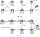
- FIG. 1(a) is a schematic diagram of a structure of a network according to an embodiment of this application.
- the network architecture is an SR-MPLS network architecture, including a plurality of network devices: a network device 1 to a network device 9.
- FIG. 1(b) is a schematic diagram of a structure of a network slice according to an embodiment of this application.
- a network device 1 to a network device 5 and a network device 7 to a network device 9 in an SR-MPLS network architecture jointly constitute a network slice 1. Therefore, one prefix-SID is allocated to each network device (for example, network devices 101 to 105 and 107 to 109) in the network slice 1, and is used as an identifier of the network device in the network slice 1.
- each network device further needs to allocate a corresponding adj-SID to a connected link, to identify a resource allocated to the network slice 1 on the link.
- FIG. 1(c) is a schematic diagram of a structure of another network slice according to an embodiment of this application.
- a network device 2 to a network device 4 and a network device 6 to a network device 9 in an SR-MPLS network architecture jointly constitute a network slice 2.
- one prefix-SID is allocated to each network device (for example, network devices 202 to 204 and 206 to 209) in the network slice 2, and is used as an identifier of the network device in the network slice 2.
- each network device further needs to allocate a corresponding adj-SID to a connected link, to identify a resource allocated to the network slice 2 on the link.
- FIG. 1(d) is a schematic diagram of a structure of another network slice according to an embodiment of this application. As shown in FIG. 1(d) , a network device 2 to a network device 4 and a network device 6 to a network device 9 in an SR-MPLS network architecture jointly constitute a network slice 3.
- a network topology corresponding to the network slice 3 is the same as a network topology corresponding to the network slice 2 in FIG. 1(c) .
- one prefix-SID also needs to be allocated to each network device (for example, network devices 302 to 304 and 306 to 309) in the network slice 3, and is used as an identifier of the network device in the network slice 3.
- each network device further needs to allocate a corresponding adj -SID to a connected link, to identify a resource allocated to the network slice 3 on the link.
- different network slices may be constituted by classifying different network topologies, and a same network topology may correspond to a plurality of different network slices. Therefore, a large quantity of network slices may be formed in the network depending on actual requirements.
- each network device needs to allocate different prefix-SIDs to different network slices, and allocate different adj-SIDs to a link connected to the network device. In other words, quantities of prefix-SIDs and adj-SIDs to be allocated are positively correlated with a quantity of network slices.
- a single MPLS label may be used to identify a network slice and a forwarding path.
- network slices are the same but links are different, and when network slices are different but links are the same, different MPLS labels are required for identification. Consequently, a large quantity of MPLS labels need to be allocated in the case of a large quantity and a large scale of network slices, causing severe consumption of MPLS label resources.
- embodiments of this application provide a packet processing method.
- An MPLS packet header is encapsulated for a packet on an MPLS data plane, and a network slice corresponding to the packet and a forwarding path of the packet are respectively indicated in the MPLS packet header via different indication information.
- network devices can normally forward the packet based on the network slice, with no need to identify the network slice and the forwarding path based on an MPLS label. This can effectively save MPLS label resources.
- SID resources can also be effectively saved by applying the packet processing method to an SR-MPLS network.
- FIG. 2 is a schematic flowchart of a packet processing method 200 according to an embodiment of this application.
- the packet processing method 200 may be applied to the network structure shown in FIG. 1(a) .
- the packet processing method 200 includes at least the following steps.
- Step 201 A first network device obtains a packet.
- the first network device may be a network device in an MPLS network or an SR-MPLS network.
- the first network device may obtain the packet in the following manners: receiving the packet sent by another network device, for example, receiving a data packet sent by a network device outside the MPLS network; generating the packet by the first network device; or receiving the packet from user equipment on an access side.
- Step 202 The first network device adds first indication information and second indication information to the packet, to obtain an updated packet, where the first indication information and the second indication information are located in an MPLS packet header of the updated packet.
- the first indication information indicates a network slice corresponding to the packet, and the second indication information indicates a forwarding path of the packet.
- the first network device updates the packet, so that the MPLS packet header in the updated packet includes the first indication information and the second indication information.
- the packet obtained by the first network device may include an MPLS packet header.
- the first network device adds the first indication information and the second indication information to the MPLS packet header, to obtain the updated packet.
- the packet obtained by the first network device may not include an MPLS header.
- the first network device adds an MPLS packet header including the first indication information and the second indication information to the packet, to obtain the updated packet.
- the first network device performing the operation of adding the first indication information and the second indication information may be a head node in the MPLS network.
- the head node may be, for example, a tunnel endpoint or a network border node.
- the first network device Before adding the first indication information and the second indication information to the packet, the first network device may determine the network slice corresponding to the packet and the forwarding path of the packet, to determine the first indication information and the second indication information.
- the first network device may determine the network slice corresponding to the packet based on information carried in the packet, or the first network device may determine the network slice corresponding to the packet based on resource information used to receive the packet.
- a policy for determining the network slice may be preconfigured in the first network device.
- the first network device may determine, according to an indication of the policy and based on a source address, a destination address, or a protocol number in the packet, the network slice corresponding to the packet, namely, a network slice used to forward the packet.
- the source address may be, for example, a source internet protocol (Internet Protocol, IP) address or a source media access control (Media Access Control, MAC) address for sending the packet, for example, an address of a user host or a base station.
- the destination address may be, for example, a destination IP address or a destination MAC address of the packet.
- the first network device may determine the network slice corresponding to the packet based on some other fields in the packet, for example, a differentiated services code point (Differentiated Services Code Point, DSCP) field or a traffic class (Traffic Class) field in an internet protocol version 4 (Internet Protocol Version 4, IPv4) or IPv6 packet header, or a virtual local area network identifier (Virtual Local Area Network identifier, VLAN ID) in an Ethernet header.
- DSCP differentiated services code point
- Traffic Class Traffic Class
- IPv4 Internet Protocol Version 4, IPv4
- IPv6 IPv6 packet header
- VLAN ID Virtual Local Area Network identifier
- the first network device may specifically determine, based on one of the foregoing fields (for example, the source address, the destination address, the protocol number, the DSCP field, or the TC field) or a combination of several fields in the foregoing fields, the network slice to which the packet belongs.
- VLAN ID Virtual Local Area Network identifier
- the first network device may establish, based on a user-side service requirement, a correspondence between a source device address for sending a service packet and a network slice. In this way, after receiving a service packet sent by a user side, the first network device may determine a corresponding network slice based on a source address in the service packet.
- the first network device may also pre-establish a correspondence between a destination address and a network slice. After receiving a service packet, the first network device may determine a corresponding network slice based on a destination address in the service packet.
- the protocol number in the packet may indicate a data protocol used for data carried in the packet.
- the first network device may alternatively determine the network slice corresponding to the packet based on the protocol number in the packet.
- the first network device may alternatively determine the network slice corresponding to the packet based on the resource information used to receive the packet, where the resource information is, for example, physical interface information or logical interface information for receiving the packet by the first network device.
- the resource information is, for example, physical interface information or logical interface information for receiving the packet by the first network device.
- the another network device may forward, based on the network slice to which the packet belongs, the packet to the inbound interface corresponding to the first network device. Therefore, the first network device may determine the network slice corresponding to the packet based on inbound interface information for receiving the packet.
- the first network device may generate the first indication information.
- the first indication information may include an identifier of the network slice, to indicate the network slice corresponding to the packet.
- the network device that receives the packet may determine, based on the identifier of the network slice in the first indication information, the network slice corresponding to the packet.
- the first network device may determine the forwarding path of the packet in the MPLS network based on the destination address of the packet, and generate the second indication information based on the forwarding path of the packet in the MPLS network.
- the second indication information may indicate the forwarding path of the packet in a plurality of manners.
- the second indication information may indicate the complete forwarding path of the packet in the MPLS network.
- the second indication information may include information about all nodes that the packet needs to pass through in a forwarding process.
- the network in FIG. 1(a) is used as an example. After receiving a packet, the network device 1 may determine that a forwarding path of the packet in the MPLS network is "network device 1--network device 2--network device 3--network device 4--network device 5". When the method provided in this embodiment of this application is applied to a conventional MPLS network, an MPLS label switching path may be pre-established using control signaling.
- Indication information generated by the network device 1 may carry only an MPLS label identifying the path, and node devices along the path switch MPLS labels (for example, a node device replaces an MPLS label A with an MPLS label B) hop by hop in a forwarding process of the packet.
- the MPLS label A in the packet received by the node device is a label allocated by the node to the path to a destination node.
- the node device may perform local table lookup based on the MPLS label A, to obtain the corresponding MPLS label B and an outbound interface for sending the packet.
- the MPLS label B is a label allocated by a next-hop node to the path to the same destination node.
- indication information generated by the network device 1 may carry information about the network device 2, the network device 3, the network device 4, and the network device 5, to indicate the complete forwarding path of the packet in the MPLS network.
- the network device 1 may include identifiers of the network device 2 to the network device 5 in a plurality of MPLS labels.
- the network device 1 may include a segment list in an MPLS label stack, and the segment list includes a plurality of SIDs that separately indicate the network device 2 to the network device 5.
- the second indication information may indicate a part of the forwarding path of the packet in the MPLS network.
- the second indication information may include information about a part of nodes that the packet needs to pass through in a forwarding process.
- the network in FIG. 1(a) is used as an example.
- indication information generated by the network device 1 may carry only information about the network device 2 and the network device 5, to indicate network devices that the packet needs to pass through in the MPLS network (in other words, the packet needs to pass through the specified network device 2 and network device 5).
- the second indication information may indicate only a tail node that the packet passes through in the MPLS network.
- the second indication information may include only information about the tail node that the packet needs to pass through in a forwarding process.
- each network device that receives the packet may forward the packet based on the tail node indicated in the second indication information and a default forwarding policy (for example, a shortest path forwarding policy).
- the second indication information may indicate the forwarding path of the packet by indicating the tail node that the packet needs to pass through.
- the forwarding path of the packet is a default path in a case in which the head node and the tail node are specified.
- the network in FIG. 1(a) is also used as an example.
- the network device 1 After the network device 1 receives a packet, the network device 1 determines to forward the packet using a default path. Therefore, indication information generated by the network device 1 may carry only information about the network device 5, to indicate a tail node that the packet needs to pass through in the MPLS network. In this way, in the forwarding process of the packet, each network device that receives the packet forwards the packet to a next network device on the default path based on the default forwarding policy, so that the packet can be finally forwarded based on the default path.
- the second indication information may indicate the former part of the complete path and indication information of information about the latter part of the complete path.
- the second indication information generated by the first network device may indicate only the former part of the complete path of the packet, and the second indication information may further indicate another node on the forwarding path of the packet to update the latter part of the path of the packet.
- the network in FIG. 1(a) is also used as an example. After receiving a packet, the network device 1 may determine that a forwarding path of the packet is "network device 1--network device 2--network device 3--network device 4--network device 5". Indication information generated by the network device 1 may carry information about the network device 2 and the network device 3, to indicate the former part of the forwarding path of the packet in the MPLS network.
- the indication information may further carry information used to indicate the network device 3 to update path information.
- the indication information carries a binding segment identifier (binding segment identifier, binding-sid), and the binding-sid indicates subsequent path information of the packet.
- the network device 3 may update the subsequent path information in the packet based on the binding-sid.
- the binding-sid may indicate an intra-domain tunnel label stack, and the tunnel label stack may carry the subsequent path information of the packet.
- the indication information generated by the network device 1 may carry identification information of the network device 2 and the network device 3 by using a plurality of MPLS labels, and the indication information may further carry the binding-sid to indicate the network device 3 to update a subsequent forwarding path.
- the binding-sid indicates the subsequent path information, so that a quantity of label stack layers encapsulated by the network device can be reduced.
- Step 203 The first network device sends the updated packet to a second network device.
- the first network device may send the updated packet to a next network device on the forwarding path.
- the second network device may be a network device on the forwarding path determined by the first network device, and the second network device is a neighboring network device of the first network device.
- the first network device may determine, based on the network slice, a forwarding resource used to send the updated packet, and the first network device sends the updated packet by using the forwarding resource.
- the forwarding resource may include one or more of the following resources: a processing resource, an outbound interface resource, and a queue resource of the first network device.
- the processing resource may be a resource used by the first network device to search for a forwarding entry used to forward the packet. More processing resources indicate higher efficiency of searching for the forwarding entry by the first network device. Therefore, a large quantity of processing resources may be configured for a network slice having a low latency requirement.
- the outbound interface resource may be an outbound interface used by the first network device to forward the packet, and the queue resource may be a forwarding queue in which the packet can enter when the first network device forwards the packet.
- a correspondence between a network slice and a forwarding resource may be preconfigured in the network device, so that the network device can determine, based on the network slice corresponding to the packet, the forwarding resource used to forward the packet.
- the first network device may further send a packet to another neighboring network device.
- the first network device may copy a payload and/or other necessary data information of the obtained packet for a plurality of times, and add corresponding network slice indication information and forwarding path indication information to each of a plurality of packets generated through copying, so that the plurality of packets are forwarded along respective forwarding paths and by using corresponding network slice resources.
- the updated packet sent by the first network device to the second network device may be a first packet.
- the first network device may further update the packet to obtain a second packet, where the second packet may include third indication information, and the third indication information indicates a forwarding path of the second packet.
- the second packet may further include the first indication information that is the same as that of the first packet, and the second packet and the first packet may use a same network slice resource.
- the first network device sends the second packet to a third network device.
- the first network device may determine a plurality of paths used for packet forwarding, and may generate a plurality of packets based on information about network devices on the corresponding paths. Different packets carry different path indication information, to indicate forwarding of the packets on different paths.
- FIG. 3 is a schematic diagram of packet forwarding according to an embodiment of this application.
- a network device 1 may determine a network slice (for example, a network slice 1) corresponding to the packet 1, and two paths used to forward the packet 1.
- the two paths may be a path 1 "network device 1--network device 2--network device 3--network device 4--network device 5" and a path 2 "network device 1--network device 7--network device 8--network device 9--network device 5".
- the network device 1 may generate a packet 2 based on the path 1, and send the packet 2 to the network device 2.
- the packet 2 includes an identifier of the network slice 1 and information (for example, identifiers of the network device 2 to the network device 5) indicating the path 1.
- the network device 1 may generate a packet 3 based on the path 2, and send the packet 3 to the network device 7.
- the packet 3 includes the identifier of the network slice 1 and information (for example, identifiers of the network device 7 to the network device 9 and the network device 5) indicating the path 2.
- the network device 1 may copy the packet 1 to generate the packet 2 and the packet 3, and then add same network slice information and different path information to the packet 2 and the packet 3, to indicate to respectively forward the packet 2 and the packet 3 along the path 1 and the path 2 by using resources of the same network slice 1.
- the first packet and the second packet carry same network slice indication information.
- the packet 2 and the packet 3 carry the same identifier of the network slice 1
- the network device 1 respectively indicates network devices that receive the packet 2 and the packet 3 on the path 2 and the path 3 to forward the packet 2 and the packet 3 by using the same network slice 1.
- the network device 1 may also forward the packet 2 and the packet 3 by using a same network slice resource.
- a forwarding resource corresponding to the network slice is a processing resource allocated on the network device 1 for packet forwarding
- a processing resource used by the network device 1 to forward the packet 2 to the network device 2 may be the same as a processing resource used by the network device 1 to forward the packet 3 to the network device 7.
- the first network device may include different network slice indication information in packets when forwarding the packets to different neighboring network devices, and may use different network slice resources. For example, when the forwarding resource corresponding to the network slice is an interface resource, an interface resource used by the first network device to forward the first packet to the second network device may be different from an interface resource used by the first network device to forward the second packet to the third network device.
- the foregoing describes a process in which the network device adds the first indication information to the packet to forward the packet.
- the following describes in detail how to add the first indication information to the MPLS packet header with reference to specific examples.
- the MPLS packet header may carry the first indication information corresponding to the packet by using an MPLS label stack or an MPLS extension header
- the MPLS packet header may include the MPLS label stack, the MPLS label stack includes first label information and second label information, the first label information indicates that the second label information carries identification information corresponding to the network slice, and the second label information carries the first identification information. Both the first label information and the second label information are located in the MPLS label stack.
- the first label information may be located above the second label information. In this way, after reading the first label information, the network device may determine that the second label information located after the first label information carries the identification information corresponding to the network slice.
- the first label information includes an extension label (Extension Label, EL) and an extended special purpose label (Extended Special Purpose Label, ESPL).
- the extension label may be located above the extended special purpose label, and a value of the extension label may be a value defined in a related standard, for example, 15, to indicate that a label located after the extension label is the extended special purpose label.
- a value of the extended special purpose label may be a predefined value, to indicate that a label located after the extended special purpose label carries the identification information corresponding to the network slice.
- the label located after the extended special purpose label may also be referred to as a network slice label.
- the MPLS label stack may include the extension label, the extended special purpose label, and the network slice label.
- the extended special purpose label is located after the extension label
- the network slice label is located after the extended special purpose label. It may be understood that the extension label, the extended special purpose label, and the network slice label are three adjacent labels, and the three adjacent labels may be located at any location in the entire MPLS label stack.
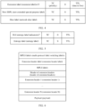
- FIG. 4 is a schematic diagram of structures of MPLS labels according to an embodiment of this application.
- a lower layer of the extension label is the extended special purpose label
- a lower layer of the extended special purpose label is the network slice label.
- each label may further include a priority (Traffic Class, TC) field, a bottom of stack field, and a time to live (Time to Live, TTL) field.
- the TC field indicates a packet priority ranging from 0 to 7.
- the bottom of stack field indicates a location of the label in the label stack.
- a value of the bottom of stack field S equal to 0 indicates that the label is not a bottom-layer label.
- a value of the bottom of stack field S equal to 1 indicates that the label is a bottom-layer label.
- the TTL field indicates time to live of the label.
- the network device may first read the upper-layer extension label, and may determine, based on a value 15 of the extension label, that a lower-layer label of the extension label is the extended special purpose label.
- the network device may determine, based on a predefined value of the extended special purpose label, that a lower-layer label of the extended special purpose label is the network slice label.
- the network device obtains the identifier corresponding to the network slice by reading the network slice label, to determine the network slice corresponding to the packet.
- the MPLS packet header includes an MPLS special purpose label
- a reserved field in the MPLS special purpose label includes the first indication information.
- the MPLS special purpose label may be a label predefined in a related standard, for example, an entropy label (Entropy Label, EL), a router alert label (Router Alert Label), or a flow identifier label (Flow-ID Label).
- the MPLS special purpose label has the reserved field, namely, a field that is reserved and has no actual use. The field may be used to carry the first indication information.
- the reserved field may include one or more of the following fields: a label value field (namely, a field indicating a specific value of the label), a TC field, and a TTL field.
- the MPLS special purpose label is the entropy label.
- FIG. 5 is a schematic diagram of structures of other MPLS labels according to an embodiment of this application.
- the MPLS packet header includes an entropy label indicator (Entropy Label Indicator, ELI) and the entropy label.
- the entropy label indicator is a previous label of the entropy label, and indicates a location of the entropy label, where a label value of the entropy label indicator may be 7.
- the network device may determine that a next label of the entropy label indicator is the entropy label.
- a format of a label value field of the entropy label may be modified, to carry the identifier of the network slice.
- 12 bits in the label value field may indicate the identifier of the network slice, and may support indication of 4,000 network slices; the remaining 8 bits in the label value field are used for load balancing.
- the network device performs hash calculation based on a value indicated by the 8 bits in the label value field, and an obtained result may be used to select one of a plurality of equivalent paths for forwarding. Different packets have different hash results. Therefore, the network device selects different paths to forward the packets. In this way, traffic balancing and forwarding are implemented among a plurality of paths.
- a 3-bit TC field and an 8-bit TTL field in the entropy label may alternatively indicate the identifier of the network slice directly.
- a field in the entropy label indicator may alternatively be used as an identifier, to indicate that the entropy label carries the identifier of the network slice.
- a special value or a bit of a TC field in the entropy label indicator may be used for identification.
- the network device may determine, based on the special value or the bit of the TC field in the entropy label indicator, that the label value field of the entropy label has been modified to indicate the identifier of the network slice.
- the MPLS packet header includes the MPLS extension header (Extension Header), and the MPLS extension header carries the first indication information.
- the MPLS packet header may include one or more MPLS extension headers.
- the MPLS extension header is located below an MPLS label stack and above an upper-layer protocol header or a packet payload.
- the MPLS extension header carrying the first indication information may be a newly defined MPLS extension header, and is specifically used to carry the first indication information.
- the MPLS extension header carrying the first indication information may alternatively be an MPLS extension header defined in a related standard, and a new type length value (type length value, TLV) is defined in the defined MPLS extension header to carry the first indication information.
- FIG. 6 is a schematic diagram of a format of the MPLS packet header according to an embodiment of this application.
- the MPLS packet header includes a label stack, extension headers, and a payload (Payload).
- the label stack includes a plurality of MPLS labels, the plurality of MPLS labels include an extension header label (Extension Header Label), and the extension header label indicates that an MPLS extension header exists in the MPLS packet header.
- a header of extension headers Header of Extension Headers
- a plurality of extension headers an extension header 1 to an extension header N
- the extension header carrying the first indication information may be one of the extension header 1 to the extension header N, for example, an extension header defined in a related standard or a newly defined extension header
- the defined MPLS extension header may carry the first indication information by carrying a new TLV
- FIG. 7 is a schematic diagram of a format of the extension header according to an embodiment of this application.
- the extension header may include a header length (Header Length) field, a header specific data (Header Specific Data) field, and a TLV field.
- the TLV field may indicate the identifier of the network slice, to carry the first indication information.
- the foregoing describes in detail a process of forwarding a packet by a head node by using an example in which the first network device is a head node.
- the following describes in detail a process of forwarding a packet by a transit node or a tail node.
- FIG. 8 is a schematic flowchart of a packet processing method 800 according to an embodiment of this application.
- the packet processing method 800 includes the following steps.
- Step 801 A first network device receives a packet sent by a second network device, where the packet includes an MPLS packet header, and the MPLS packet header includes first indication information and second indication information.
- the first network device may be a transit node or a tail node in an MPLS network or an SR-MPLS network
- the second network device may be a head node or a transit node in the MPLS network or the SR-MPLS network.
- the packet received by the first network device includes the first indication information and the second indication information.
- the first indication information indicates a network slice corresponding to the packet
- the second indication information indicates a forwarding path corresponding to the packet.
- the second indication information carried in the packet received by the first network device may be complete path indication information initially added by the second network device to the packet, and the second network device may be, for example, a head node.
- the first network device is a next network device on the forwarding path determined by the second network device.
- FIG. 3 is used as an example. If a network device 1 is a head node, a network device 2 is a next network device on a forwarding path 1 determined by the network device 1 for a packet 2, namely, the first transit node on the path 1.
- second indication information that is received by the network device 2 and that indicates the forwarding path is complete information that is added by the network device 1 and that indicates the path 1.
- the complete information may be information indicating the hop-by-hop forwarding path in the MPLS network as described above, information indicating a part of specified nodes on the path for forwarding, information indicating a tail node, or the like.
- the second network device is a transit node
- the first network device is a next network device located after the second network device on the forwarding path
- the second indication information carried in the packet received by the first network device may be partial path indication information, that is, information indicating a part of a path from the first network device to a destination device.
- FIG. 3 is used as an example. If a network device 1 is a head node, a network device 2 is a next network device on a forwarding path 1 determined by the network device 1 for a packet 2, namely, the first transit node on the path 1, and a network device 3 is a next network device located after the network device 2 on the path 1, namely, the second transit node on the path 1.
- Second indication information that is received by the network device 2 and that indicates the forwarding path may be complete information that is added by the network device 1 and that indicates the path 1, and the complete information may be information indicating the hop-by-hop forwarding path in an SR-MPLS network.
- the complete information includes an identifier 2 indicating the network device 2, an identifier 3 indicating the network device 3, and an identifier 4 indicating a network device 4.
- Second indication information that is received by the network device 3 and that indicates the forwarding path may be information indicating a part of the path 1, and the information indicating the part of the path 1 may be information indicating a hop-by-hop forwarding path from the network device 3 to the network device 4 in the SR-MPLS network.
- the second indication information in the packet received by the network device 3 may include the identifier 3 indicating the network device 3 and the identifier 4 indicating the network device 4, that is, the information indicating the part of the path 1.
- the first network device may also receive complete path information added by a head node, for example, indication information that is added by the head node and that indicates only a tail node.
- complete path information added by a head node for example, indication information that is added by the head node and that indicates only a tail node.
- the first network device receives the packet including the second indication information from a previous transit node, other transit nodes including the previous transit node do not update the second indication information added by the head node. Therefore, in this case, the second indication information included in the packet received by the first network device is still the complete path information added by the head node.
- the first network device may alternatively be a tail node.
- the second indication information received by the tail node may include an identifier of the tail node.
- the tail node may be an endpoint of one tunnel, an endpoint of several tunnels that are stitched, or a domain border node of a network domain or a management domain.
- Step 802 The first network device determines the network slice corresponding to the packet based on the first indication information.
- the first indication information may include an identifier of the network slice, to indicate the network slice corresponding to the packet.
- the first network device may determine the network slice corresponding to the packet based on the identifier of the network slice in the first indication information.
- Step 803 The first network device forwards an updated packet to a third network device by using the network slice, where the third network device is a device on the forwarding path of the packet and is determined based on the second indication information.
- the first network device may determine, based on the packet forwarding path indicated by the second indication information, that the third network device is a next network device on the forwarding path. Therefore, the first network device may determine, based on the network slice, a forwarding resource corresponding to the packet, that is, a forwarding resource allocated by the first network device to the network slice corresponding to the packet, and forward the updated packet to the third network device by using the forwarding resource corresponding to the network slice.
- the forwarding resource may include one or more of the following resources: a processing resource, an outbound interface resource, and a queue resource of the first network device.
- a process in which the first network device determines the forwarding resource corresponding to the network slice and forwards the packet by using the forwarding resource is similar to that in the embodiment shown in FIG. 2 .
- the first network device may also determine, based on the network slice, other information related to packet forwarding, such as network topology information, to forward the packet based on the determined other information.
- the second indication information may include a tunnel label used to identify a node or a link on the forwarding path, and may further include a service label, for example, a virtual private network (Virtual Private Network, VPN) label, used to identify a service.
- a manner in which the tail node determines the third network device based on the second indication information may be: determining, based on the VPN label, an outbound interface and a next-hop network device (namely, the third network device) that are used to forward the service packet.
- the first network device updates the received packet to obtain the updated packet.
- the updated packet includes the first indication information, or the updated packet includes updated first indication information.
- the updated first indication information is determined based on the first indication information, and the updated first indication information indicates the network slice corresponding to the updated packet.
- network devices in the plurality of network domains may form a complete network slice, and quantities or types of resources allocated to a plurality of network slices in the plurality of network domains may be the same or may be different.
- network slice identifiers used in different network domains may be different, even though resources configured for network slices in the different network domains are the same. Therefore, when the first network device is a boundary device that is in a network domain and that is connected to another network domain, the first network device may update the first indication information in the received packet, to obtain the updated first indication information.
- the updated first indication information indicates a corresponding network slice identifier in a next network domain.
- network devices in a network domain 1 and a network domain 2 form a complete network slice 1, a network slice identifier corresponding to the network slice 1 in the network domain 1 is "001", and a network slice identifier corresponding to the network slice 1 in the network domain 2 is "002" .
- the first network device is a boundary device that is in the network domain 1 and that is connected to the network domain 2.
- the first network device receives a packet 1 forwarded by a network device in the network domain 1, where the packet 1 carries the network slice identifier "001".
- the first network device may update the packet 1 to obtain an updated packet 1.
- the updated packet 1 includes an updated network slice identifier, and the updated network slice identifier is "002".
- the updated packet includes updated second indication information
- the updated second indication information indicates a forwarding path of the updated packet.
- the first network device may update the second indication information based on the indication information of the information about the latter part of the path indicated in the second indication information, to obtain the updated second indication information, where the updated second indication information indicates the forwarding path of the updated packet. In this way, when the first network device forwards the updated packet, the updated packet includes the updated second indication information, to indicate a subsequent forwarding path of the updated packet.
- the first network device may alternatively be a tail node in the MPLS network or the SR-MPLS network.
- the first network device may decapsulate the packet to obtain a decapsulated packet, where the decapsulated packet does not include the MPLS packet header added by the head node.
- the first network device when the first network device is a tail node in the MPLS network or the SR-MPLS network, the first network device needs to forward the packet outside the MPLS network or the SR-MPLS network. Therefore, the first network device may decapsulate the packet, to remove the MPLS packet header from the packet, so as to avoid a case in which a network device outside the MPLS network or the SR-MPLS network cannot identify the packet.
- the packet may carry an MPLS label stack before entering the MPLS network.
- the head node of the MPLS network adds a new MPLS label stack to the original MPLS label stack, to indicate the network slice corresponding to the packet and the forwarding path of the packet.
- the tail node decapsulates only the MPLS label stack added by the head node, and retains the original MPLS label stack in the packet. Therefore, the decapsulated packet obtained after the tail node decapsulates the packet still includes the MPLS label stack carried before the packet enters the MPLS network. In this case, the decapsulated packet forwarded by the tail node still includes an MPLS packet header carrying the original MPLS label stack.
- the first network device may not perform the foregoing steps 802 and 803. However, after performing step 801, the first network device performs a removal operation on MPLS packet header information added by the head node, then searches for and determines, based on other information carried in the packet such as a destination IP address, a device for receiving the packet, and forwards the packet to the device.
- the device for receiving the packet may be, for example, a device on a user access side.
- the foregoing embodiments use the example in which the first network device is a network device in the MPLS network or the SR-MPLS network to describe scenarios to which the packet processing method provided in embodiments of this application is applied.
- the packet processing method provided in embodiments of this application may be further applied to a network scenario in which a network slice corresponding to a packet needs to be indicated.
- a network scenario to which embodiments of this application are applied is not uniquely limited herein.
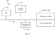
- FIG. 9 is a schematic diagram of a structure of a network device 900 according to an embodiment of this application.
- the network device 900 shown in FIG. 9 shows some specific features, a person skilled in the art may be aware from embodiments of this application that, for brevity, FIG. 9 does not show various other features, to avoid confusing more related aspects of the implementations disclosed in embodiments of this application.
- the network device 900 includes one or more processing units (CPU) 901, a network interface 902, a programming interface 903, a memory 904, and one or more communication buses 905 that are configured to interconnect various components.
- CPU processing units
- the network interface 902 includes one or more network interface 902, a programming interface 903, a memory 904, and one or more communication buses 905 that are configured to interconnect various components.
- some functional components or units may be omitted or added to the network device 900 based on the foregoing example.
- the network interface 902 is configured to connect to one or more other network devices/servers in a network system.
- the communication bus 905 includes a circuit that interconnects system components and controls communication between the system components.
- the memory 904 may include a non-volatile memory, for example, a read-only memory (read-only memory, ROM), a programmable read-only memory (programmable ROM, PROM), an erasable programmable read-only memory (erasable PROM, EPROM), an electrically erasable programmable read-only memory (electrically EPROM, EEPROM), or a flash memory.
- the memory 904 may also include a volatile memory.
- the volatile memory may be a random access memory (random access memory, RAM), and is used as an external cache.
- a non-transitory computer-readable storage medium of the memory 904 or the memory 904 stores the following programs, modules, and data structures, or a subset thereof, and for example, includes a transceiver unit (not shown in the figure), an obtaining unit 9041, and a processing unit 9042.
- the network device 900 may have any function of the first network device in the method 200 or the first network device in the method 800.
- the transceiver unit in the network device 900 is configured to perform step 203, step 801, or step 803.
- the obtaining unit 9041 is configured to perform step 201.
- the processing unit 9042 is configured to perform step 202 or step 802.
- the network device 900 corresponds to the first network device in the foregoing method embodiments, and the modules in the network device 900 and the foregoing other operations and/or functions are separately used to implement various steps and methods implemented by the first network device in the method embodiments.
- the modules in the network device 900 and the foregoing other operations and/or functions are separately used to implement various steps and methods implemented by the first network device in the method embodiments.
- transceiver unit may be implemented by the processor by invoking program code in the memory, and cooperation with the network interface 902 is performed when necessary.
- a data receiving/sending operation may be completed by the network interface 902 on the network device 900.
- the network device 900 is configured to perform the service processing method provided in embodiments of this application, for example, perform the packet processing method corresponding to the embodiment shown in FIG. 2 or FIG. 8 .
- an embodiment of this application further provides a network device.
- the following describes a hardware structure of the network device.
- FIG. 10 is a schematic diagram of a structure of a network device 1000 according to an embodiment of this application.
- the network device 1000 may be configured as the first network device in the foregoing method embodiments.
- the network device 1000 may correspond to the first network device in the foregoing method embodiments.
- Hardware and modules in the network device 1000 and the foregoing other operations and/or functions are separately used to implement various steps and methods implemented by the first network device in the method embodiments.
- the steps of the foregoing method 200 or method 800 are completed by using an integrated logic circuit of hardware in a processor of the network device 1000 or by using instructions in a form of software.
- the steps in the methods disclosed with reference to embodiments of this application may be directly performed and completed by a hardware processor, or may be performed and completed by using a combination of hardware in the processor and a software module.
- the software module may be located in a mature storage medium in the art, such as a random access memory, a flash memory, a read-only memory, a programmable read-only memory, an electrically erasable programmable memory, or a register.
- the storage medium is located in a memory, and the processor reads information in the memory and completes the steps in the foregoing method in combination with the hardware of the processor. To avoid repetition, details are not described herein again.
- the network device 1000 may also correspond to the network device 900 in the foregoing virtual apparatus embodiment, and each functional module in the network device 900 is implemented by using software and hardware of the network device 1000.
- the functional modules included in the network device 900 are generated after the processor of the network device 1000 reads program code stored in the memory, or are implemented by the processor of the network device 1000 by reading program code stored in the memory and cooperating with a communication interface.
- the network device 1000 includes a main control board 1010 and an interface board 1030.
- the main control board 1010 is also referred to as a main processing unit (main processing unit, MPU) or a route processing card (route processor card).
- the main control board 1010 controls and manages components in the network device 1000, including functions such as routing calculation, device management, device maintenance, and protocol processing.
- the main control board 1010 includes a central processing unit 1011 and a memory 1012.
- the interface board 1030 is also referred to as a line interface unit card (line processing unit, LPU), a line card (line card), or a service board.
- the interface board 1030 is configured to: provide various service interfaces, and forward a data packet.
- the service interfaces include but are not limited to an Ethernet interface, a POS (Packet over SONET/SDH) interface, and the like.
- the Ethernet interface is, for example, a flexible Ethernet service interface (Flexible Ethernet Clients, FlexE Clients).
- the interface board 1030 includes a central processing unit 1031, a network processor 1032, a forwarding entry memory 1034, and a physical interface card (physical interface card, PIC) 1033.
- the central processing unit 1031 on the interface board 1030 is configured to: control and manage the interface board 1030, and communicate with the central processing unit 1011 on the main control board 1010.
- the network processor 1032 is configured to forward a packet.
- a form of the network processor 1032 may be a forwarding chip. Specifically, processing on an uplink packet includes processing at a packet ingress interface and forwarding table lookup, and processing on a downlink packet includes forwarding table lookup and the like.
- the physical interface card 1033 is configured to implement a physical layer interconnection function. Original traffic enters the interface board 1030 from the physical interface card 1033, and a processed packet is sent out from the physical interface card 1033.
- the physical interface card 1033 includes at least one physical interface, and the physical interface is also referred to as a physical port.
- the physical interface card 1033 corresponds to a FlexE physical interface in a system architecture.
- the physical interface card 1033 also referred to as a subcard, may be mounted on the interface board 1030, and is responsible for converting an optical/electrical signal into a packet, performing validity check on the packet, and forwarding the packet to the network processor 1032 for processing.
- the central processing unit 1031 on the interface board 1003 may also perform a function of the network processor 1032, for example, implement software forwarding based on a general-purpose CPU, so that the network processor 1032 is not required in the physical interface card 1033.
- the network device 1000 includes a plurality of interface boards.
- the network device 1000 further includes an interface board 1040, and the interface board 1040 includes a central processing unit 1041, a network processor 1042, a forwarding entry memory 1044, and a physical interface card 1043.
- the network device 1000 further includes a switching board 1020.
- the switching board 1020 may also be referred to as a switch fabric unit (switch fabric unit, SFU).
- switch fabric unit switch fabric unit
- the switching board 1020 is configured to complete data exchange between the interface boards.
- the interface board 1030 and the interface board 1040 may communicate with each other via the switching board 1020.
- the main control board 1010 is coupled to the interface board 1030.
- the main control board 1010, the interface boards 1030 and 1040, and the switching board 1020 are connected to a system backplane through a system bus to communicate with each other.
- an inter-process communication (inter-process communication, IPC) channel is established between the main control board 1010 and the interface board 1030, and the main control board 1010 communicates with the interface board 1030 through the IPC channel.
- IPC inter-process communication
- the network device 1000 includes a control plane and a forwarding plane.
- the control plane includes the main control board 1010 and the central processing unit 1031.
- the forwarding plane includes components that perform forwarding, such as the forwarding entry memory 1034, the physical interface card 1033, and the network processor 1032.
- the control plane performs functions such as routing, generating a forwarding table, processing signaling and a protocol packet, and configuring and maintaining a device status.
- the control plane delivers the generated forwarding table to the forwarding plane.
- the network processor 1032 forwards a packet received by the physical interface card 1033.
- the forwarding table delivered by the control plane may be stored in the forwarding entry memory 1034. In some embodiments, the control plane and the forwarding plane may be completely separated, and are not on a same device.
- the central processing unit 1011 may obtain a packet, and add first indication information and second indication information to the packet, to obtain an updated packet.
- the network processor 1032 triggers the physical interface card 1033 to send the updated packet to a second network device.
- the central processing unit 1011 may obtain a packet, and determine, based on first indication information in the packet, a network slice corresponding to the packet.
- the network processor 1032 triggers the physical interface card 1033 to send an updated packet to a second network device.
- the transceiver unit in the network device 900 may be equivalent to the physical interface card 1033 or the physical interface card 1043 in the network device 1000, and the obtaining unit 9041 and the processing unit 9042 in the network device 900 may be equivalent to the central processing unit 1011 or the central processing unit 1031 in the network device 1000.
- the network device 1000 in this embodiment may correspond to the first network device or the second network device in the foregoing method embodiments.
- the main control board 1010, and the interface board 1030 and/or the interface board 1040 in the network device 1000 may implement functions and/or various steps implemented by the first network device or the second network device in the foregoing method embodiments. For brevity, details are not described herein again.
- main control boards there may be one or more main control boards, and when there are a plurality of main control boards, the main control boards may include an active main control board and a standby main control board. There may be one or more interface boards, and a network device having a stronger data processing capability provides more interface boards. There may also be one or more physical interface cards on the interface board. There may be no switching board or one or more switching boards. When there are a plurality of switching boards, load balancing and redundancy backup may be implemented together. In a centralized forwarding architecture, the network device may not need the switching board, and the interface board provides a function of processing service data of an entire system.
- the network device may have at least one switching board, and data exchange between a plurality of interface boards is implemented by using the switching board, to provide a large-capacity data exchange and processing capability. Therefore, a data access and processing capability of a network device in the distributed architecture is better than that of a device in the centralized architecture.
- the network device may alternatively be in a form in which there is only one card. To be specific, there is no switching board, and functions of the interface board and the main control board are integrated on the card. In this case, the central processing unit on the interface board and the central processing unit on the main control board may be combined into one central processing unit on the card, to perform functions obtained after the two central processing units are combined.
- the device in this form (for example, a network device such as a low-end switch or router) has a weak data exchange and processing capability. Which architecture is specifically used depends on a specific networking deployment scenario, and is not uniquely limited herein.
- the first network device or the second network device may be implemented as a virtualized device.
- the virtualized device may be a virtual machine (English: Virtual Machine, VM) on which a program having a packet sending function is run, and the virtual machine is deployed on a hardware device (for example, a physical server).
- the virtual machine is a complete software-simulated computer system that has complete hardware system functions and that runs in an entirely isolated environment.
- the virtual machine may be configured as the first network device or the second network device.
- the first network device or the second network device may be implemented based on a general-purpose physical server in combination with a network functions virtualization (Network Functions Virtualization, NFV) technology.
- Network Functions Virtualization Network Functions Virtualization
- the first network device or the second network device is a virtual host, a virtual router, or a virtual switch.
- a person skilled in the art may virtualize, on the general-purpose physical server, the first network device or the second network device having the foregoing functions. Details are not described herein.
- network devices in the foregoing product forms separately have any function of the first network device or the second network device in the foregoing method embodiments, and details are not described herein.
- An embodiment of this application provides a computer program product.
- the computer program product runs on a network device
- the network device is enabled to perform the method performed by the first network device in the method 200 or the method 800.
- an embodiment of this application provides a network system 1100.
- the system 1100 includes a network device 1101 and a network device 1102.
- the network device 1101 may be the first network device in the method 200, the network device 900, or the network device 1000, and the network device 1101 may be a head node in a network.
- the network device 1102 may be the first network device in the method 800, the network device 900, or the network device 1000, and the network device 1102 may be a transit node in the network.
- the system 1100 may further include a network device 1103, the network device 1103 may be the network device 900 or the network device 1000, and the network device 1103 may be a tail node in the network.
- An embodiment of this application further provides a chip, including a processor and an interface circuit.
- the interface circuit is configured to receive an instruction and transmit the instruction to the processor.
- the processor is coupled to a memory, the memory is configured to store a program or instructions, and when the program or the instructions are executed by the processor, the chip system is enabled to implement the method in any one of the foregoing method embodiments.
- processors in the chip system there may be one or more processors in the chip system.
- the processor may be implemented by using hardware, or may be implemented by using software.
- the processor When the processor is implemented by using the hardware, the processor may be a logic circuit, an integrated circuit, or the like.
- the processor When the processor is implemented by using the software, the processor may be a general-purpose processor, and is implemented by reading software code stored in the memory.
- the memory may be integrated with the processor, or may be disposed independent of the processor.
- the memory may be a non-transitory processor, for example, a read-only memory ROM.
- the memory and the processor may be integrated into a same chip, or may be separately disposed on different chips.
- a type of the memory and a manner of disposing the memory and the processor are not specifically limited in this application.
- the chip system may be a field programmable gate array (field programmable gate array, FPGA), an application-specific integrated circuit (application-specific integrated circuit, ASIC), a system on chip (system on chip, SoC), a central processing unit (central processing unit, CPU), a network processor (network processor, NP), a digital signal processing circuit (digital signal processor, DSP), a microcontroller (microcontroller unit, MCU), a programmable controller (programmable logic device, PLD), or another integrated chip.
- field programmable gate array field programmable gate array
- ASIC application-specific integrated circuit
- SoC system on chip
- CPU central processing unit
- CPU central processing unit
- NP network processor
- DSP digital signal processing circuit
- microcontroller unit, MCU microcontroller unit
- PLD programmable logic device
- Steps in the methods in embodiments of this application may be sequentially scheduled, combined, or deleted based on an actual requirement.
- Modules in the apparatuses in embodiments of this application may be divided, combined, or deleted based on an actual requirement.
- B corresponding to A indicates that B is associated with A, and B may be determined based on A.
- determining B based on A does not mean that B is determined based on A only, and B may alternatively be determined based on A and/or other information.
- the disclosed system, apparatus, and method may be implemented in other manners.
- the described apparatus embodiments are merely examples.
- division into the units is merely logical function division and may be other division during actual implementation.
- a plurality of units or components may be combined or integrated into another system, or some features may be ignored or not performed.
- the displayed or discussed mutual couplings or direct couplings or communication connections may be implemented through some interfaces.
- the indirect couplings or communication connections between the apparatuses or the units may be implemented in electrical, mechanical, or other forms.
- the units described as separate parts may or may not be physically separate, and parts displayed as units may or may not be physical units, in other words, may be located in one position, or may be distributed on a plurality of network units. Some or all of the units may be selected based on actual requirements to achieve the objectives of the solutions of embodiments.
- functional units in embodiments of this application may be integrated into one processing unit, or each of the units may exist alone physically, or two or more units may be integrated into one unit.
- the integrated unit may be implemented in a form of hardware, or may be implemented in a form of a software functional unit.
- the integrated unit When the integrated unit is implemented in the form of a software functional unit and sold or used as an independent product, the integrated unit may be stored in a computer-readable storage medium. Based on such an understanding, the technical solutions of this application essentially, or the part contributing to the current technology, or all or some of the technical solutions may be implemented in a form of a software product.
- the computer software product is stored in a storage medium and includes several instructions for instructing a computer device (which may be a personal computer, a server, a network device/server, or the like) to perform all or some of the steps of the methods in embodiments of this application.
- the foregoing storage medium includes any medium that can store program code, such as a USB flash drive, a removable hard disk, a read-only memory, a random access memory, a magnetic disk, or an optical disc.
Landscapes
- Engineering & Computer Science (AREA)
- Computer Networks & Wireless Communication (AREA)
- Signal Processing (AREA)
- Computer Security & Cryptography (AREA)
- Data Exchanges In Wide-Area Networks (AREA)
Applications Claiming Priority (3)
| Application Number | Priority Date | Filing Date | Title |
|---|---|---|---|
| CN202010638513 | 2020-07-06 | ||
| CN202011022649.5A CN113973082B (zh) | 2020-07-06 | 2020-09-25 | 一种报文处理方法及网络设备 |
| PCT/CN2021/104000 WO2022007702A1 (zh) | 2020-07-06 | 2021-07-01 | 一种报文处理方法及网络设备 |
Publications (2)
| Publication Number | Publication Date |
|---|---|
| EP4161002A1 true EP4161002A1 (de) | 2023-04-05 |
| EP4161002A4 EP4161002A4 (de) | 2023-12-20 |
Family
ID=79553510
Family Applications (1)
| Application Number | Title | Priority Date | Filing Date |
|---|---|---|---|
| EP21838070.7A Pending EP4161002A4 (de) | 2020-07-06 | 2021-07-01 | Nachrichtenverarbeitungsverfahren und netzwerkvorrichtung |
Country Status (5)
| Country | Link |
|---|---|
| US (1) | US20230155930A1 (de) |
| EP (1) | EP4161002A4 (de) |
| JP (1) | JP7674401B2 (de) |
| MX (1) | MX2023000301A (de) |
| WO (1) | WO2022007702A1 (de) |
Families Citing this family (6)
| Publication number | Priority date | Publication date | Assignee | Title |
|---|---|---|---|---|
| CN114827019B (zh) * | 2018-07-13 | 2023-08-22 | 华为技术有限公司 | 用于在网业务的mpls扩展头 |
| US11956306B1 (en) * | 2022-03-30 | 2024-04-09 | Nvidia Corporation | Multicast-reduction assisted by network devices |
| CN117201379B (zh) * | 2022-05-31 | 2026-01-06 | 中兴通讯股份有限公司 | 业务传输方法、设备和存储介质 |
| CN119011337A (zh) * | 2023-05-19 | 2024-11-22 | 华为技术有限公司 | 报文转发方法、装置及系统 |
| WO2025095829A1 (en) * | 2023-11-02 | 2025-05-08 | Telefonaktiebolaget Lm Ericsson (Publ) | Radio acess network nodes, intermediate node and methods for handling packet streams in a ran transport network |
| WO2025095828A1 (en) * | 2023-11-02 | 2025-05-08 | Telefonaktiebolaget Lm Ericsson (Publ) | Network nodes, intermediate node and methods for handling packets in a backhaul/midhaul transport network |
Family Cites Families (8)
| Publication number | Priority date | Publication date | Assignee | Title |
|---|---|---|---|---|
| CN104113482B (zh) * | 2014-07-23 | 2017-11-24 | 华为技术有限公司 | 流表更新的方法、装置和系统 |
| EP3306871B1 (de) * | 2015-11-27 | 2021-08-11 | Huawei Technologies Co., Ltd. | Verfahren und vorrichtung zur erfassung von weginformationen |
| CN107306222B (zh) * | 2016-04-25 | 2020-09-25 | 华为技术有限公司 | 标签交换路径上的流量工程隧道建立的方法和设备 |
| CN110535766B (zh) * | 2018-05-25 | 2021-10-22 | 华为技术有限公司 | 一种生成路由的方法和设备 |
| WO2020048493A1 (en) | 2018-09-05 | 2020-03-12 | Huawei Technologies Co., Ltd. | Segment routing in mpls network |
| CN110912795B (zh) | 2018-09-14 | 2022-04-15 | 中兴通讯股份有限公司 | 一种传输控制方法、节点、网络系统及存储介质 |
| CN111385207B (zh) * | 2018-12-29 | 2022-08-19 | 中兴通讯股份有限公司 | 一种业务数据的转发方法、网络设备及网络系统 |
| CN110932895B (zh) | 2019-11-26 | 2022-07-15 | 中国联合网络通信集团有限公司 | 一种网络切片的报文转发方法和装置 |
-
2021
- 2021-07-01 MX MX2023000301A patent/MX2023000301A/es unknown
- 2021-07-01 EP EP21838070.7A patent/EP4161002A4/de active Pending
- 2021-07-01 WO PCT/CN2021/104000 patent/WO2022007702A1/zh not_active Ceased
- 2021-07-01 JP JP2022581598A patent/JP7674401B2/ja active Active
-
2023
- 2023-01-05 US US18/150,698 patent/US20230155930A1/en active Pending
Also Published As
| Publication number | Publication date |
|---|---|
| MX2023000301A (es) | 2023-02-09 |
| US20230155930A1 (en) | 2023-05-18 |
| WO2022007702A1 (zh) | 2022-01-13 |
| JP7674401B2 (ja) | 2025-05-09 |
| EP4161002A4 (de) | 2023-12-20 |
| JP2023532737A (ja) | 2023-07-31 |
Similar Documents
| Publication | Publication Date | Title |
|---|---|---|
| CN113973082B (zh) | 一种报文处理方法及网络设备 | |
| US20230155930A1 (en) | Packet Processing Method and Network Device | |
| US12368669B2 (en) | Packet sending method, device, and system | |
| EP3832957B1 (de) | Übertragungssteuerungsverfahren, knoten, netzwerksystem und speichermedium | |
| US20230412508A1 (en) | Packet processing method and related apparatus | |
| US20220200820A1 (en) | Packet Sending Method and Apparatus | |
| EP3902211B1 (de) | Paketweiterleitungsverfahren und netzwerkvorrichtung | |
| EP3902207B1 (de) | Paketweiterleitungsverfahren und netzwerkvorrichtung | |
| CN114095305A (zh) | Bier报文转发的方法、设备以及系统 | |
| CN115865769A (zh) | 报文处理方法、网络设备及系统 | |
| US20210359879A1 (en) | Packet forwarding method and network device | |
| US20250071054A1 (en) | Route Processing Method and Network Device | |
| US12224926B2 (en) | Route processing method and network device | |
| US20240348476A1 (en) | Vxlan packet transmission method, network device, and system | |
| CN116418628A (zh) | 一种vxlan报文传输方法、网络设备及系统 | |
| CN112822104A (zh) | 一种数据报文的处理方法、设备、存储介质及系统 | |
| US20250097139A1 (en) | Packet sending method, network device, and system | |
| CN117097656A (zh) | 一种报文处理的方法及相关设备 |
Legal Events
| Date | Code | Title | Description |
|---|---|---|---|
| STAA | Information on the status of an ep patent application or granted ep patent |
Free format text: STATUS: THE INTERNATIONAL PUBLICATION HAS BEEN MADE |
|
| PUAI | Public reference made under article 153(3) epc to a published international application that has entered the european phase |
Free format text: ORIGINAL CODE: 0009012 |
|
| STAA | Information on the status of an ep patent application or granted ep patent |
Free format text: STATUS: REQUEST FOR EXAMINATION WAS MADE |
|
| 17P | Request for examination filed |
Effective date: 20230102 |
|
| AK | Designated contracting states |
Kind code of ref document: A1 Designated state(s): AL AT BE BG CH CY CZ DE DK EE ES FI FR GB GR HR HU IE IS IT LI LT LU LV MC MK MT NL NO PL PT RO RS SE SI SK SM TR |
|
| DAV | Request for validation of the european patent (deleted) | ||
| DAX | Request for extension of the european patent (deleted) | ||
| A4 | Supplementary search report drawn up and despatched |
Effective date: 20231122 |
|
| RIC1 | Information provided on ipc code assigned before grant |
Ipc: H04L 47/78 20220101ALI20231116BHEP Ipc: H04L 45/50 20220101ALI20231116BHEP Ipc: H04L 45/00 20220101ALI20231116BHEP Ipc: H04L 12/46 20060101AFI20231116BHEP |
|
| STAA | Information on the status of an ep patent application or granted ep patent |
Free format text: STATUS: EXAMINATION IS IN PROGRESS |
|
| 17Q | First examination report despatched |
Effective date: 20251202 |