EP4161061B1 - Procédé d'acquisition d'image, ensemble caméra, et terminal mobile - Google Patents
Procédé d'acquisition d'image, ensemble caméra, et terminal mobile Download PDFInfo
- Publication number
- EP4161061B1 EP4161061B1 EP21838012.9A EP21838012A EP4161061B1 EP 4161061 B1 EP4161061 B1 EP 4161061B1 EP 21838012 A EP21838012 A EP 21838012A EP 4161061 B1 EP4161061 B1 EP 4161061B1
- Authority
- EP
- European Patent Office
- Prior art keywords
- color
- pixel
- image
- filtered
- image data
- Prior art date
- Legal status (The legal status is an assumption and is not a legal conclusion. Google has not performed a legal analysis and makes no representation as to the accuracy of the status listed.)
- Active
Links
Images


Classifications
-
- H—ELECTRICITY
- H04—ELECTRIC COMMUNICATION TECHNIQUE
- H04N—PICTORIAL COMMUNICATION, e.g. TELEVISION
- H04N19/00—Methods or arrangements for coding, decoding, compressing or decompressing digital video signals
- H04N19/10—Methods or arrangements for coding, decoding, compressing or decompressing digital video signals using adaptive coding
- H04N19/102—Methods or arrangements for coding, decoding, compressing or decompressing digital video signals using adaptive coding characterised by the element, parameter or selection affected or controlled by the adaptive coding
- H04N19/132—Sampling, masking or truncation of coding units, e.g. adaptive resampling, frame skipping, frame interpolation or high-frequency transform coefficient masking
-
- H—ELECTRICITY
- H04—ELECTRIC COMMUNICATION TECHNIQUE
- H04N—PICTORIAL COMMUNICATION, e.g. TELEVISION
- H04N25/00—Circuitry of solid-state image sensors [SSIS]; Control thereof
- H04N25/10—Circuitry of solid-state image sensors [SSIS]; Control thereof for transforming different wavelengths into image signals
- H04N25/11—Arrangement of colour filter arrays [CFA]; Filter mosaics
- H04N25/13—Arrangement of colour filter arrays [CFA]; Filter mosaics characterised by the spectral characteristics of the filter elements
- H04N25/133—Arrangement of colour filter arrays [CFA]; Filter mosaics characterised by the spectral characteristics of the filter elements including elements passing panchromatic light, e.g. filters passing white light
-
- G—PHYSICS
- G06—COMPUTING OR CALCULATING; COUNTING
- G06T—IMAGE DATA PROCESSING OR GENERATION, IN GENERAL
- G06T3/00—Geometric image transformations in the plane of the image
- G06T3/40—Scaling of whole images or parts thereof, e.g. expanding or contracting
- G06T3/4015—Image demosaicing, e.g. colour filter arrays [CFA] or Bayer patterns
-
- H—ELECTRICITY
- H04—ELECTRIC COMMUNICATION TECHNIQUE
- H04N—PICTORIAL COMMUNICATION, e.g. TELEVISION
- H04N23/00—Cameras or camera modules comprising electronic image sensors; Control thereof
- H04N23/10—Cameras or camera modules comprising electronic image sensors; Control thereof for generating image signals from different wavelengths
- H04N23/12—Cameras or camera modules comprising electronic image sensors; Control thereof for generating image signals from different wavelengths with one sensor only
-
- H—ELECTRICITY
- H04—ELECTRIC COMMUNICATION TECHNIQUE
- H04N—PICTORIAL COMMUNICATION, e.g. TELEVISION
- H04N23/00—Cameras or camera modules comprising electronic image sensors; Control thereof
- H04N23/70—Circuitry for compensating brightness variation in the scene
- H04N23/73—Circuitry for compensating brightness variation in the scene by influencing the exposure time
-
- H—ELECTRICITY
- H04—ELECTRIC COMMUNICATION TECHNIQUE
- H04N—PICTORIAL COMMUNICATION, e.g. TELEVISION
- H04N23/00—Cameras or camera modules comprising electronic image sensors; Control thereof
- H04N23/80—Camera processing pipelines; Components thereof
-
- H—ELECTRICITY
- H04—ELECTRIC COMMUNICATION TECHNIQUE
- H04N—PICTORIAL COMMUNICATION, e.g. TELEVISION
- H04N23/00—Cameras or camera modules comprising electronic image sensors; Control thereof
- H04N23/80—Camera processing pipelines; Components thereof
- H04N23/84—Camera processing pipelines; Components thereof for processing colour signals
-
- H—ELECTRICITY
- H04—ELECTRIC COMMUNICATION TECHNIQUE
- H04N—PICTORIAL COMMUNICATION, e.g. TELEVISION
- H04N23/00—Cameras or camera modules comprising electronic image sensors; Control thereof
- H04N23/80—Camera processing pipelines; Components thereof
- H04N23/84—Camera processing pipelines; Components thereof for processing colour signals
- H04N23/843—Demosaicing, e.g. interpolating colour pixel values
-
- H—ELECTRICITY
- H04—ELECTRIC COMMUNICATION TECHNIQUE
- H04N—PICTORIAL COMMUNICATION, e.g. TELEVISION
- H04N5/00—Details of television systems
- H04N5/222—Studio circuitry; Studio devices; Studio equipment
- H04N5/262—Studio circuits, e.g. for mixing, switching-over, change of character of image, other special effects ; Cameras specially adapted for the electronic generation of special effects
- H04N5/265—Mixing
-
- H—ELECTRICITY
- H04—ELECTRIC COMMUNICATION TECHNIQUE
- H04N—PICTORIAL COMMUNICATION, e.g. TELEVISION
- H04N9/00—Details of colour television systems
- H04N9/64—Circuits for processing colour signals
Definitions
- the disclosure relates to the field of imaging technologies, and more particularly to an image acquisition method, a camera assembly, and a mobile terminal.
- a camera may be installed in an electronic device such as a mobile phone, enabling the electronic device with an image acquisition function.
- the camera may be provided with a color filter array therein to acquire a color image.
- the color filter array in the camera is usually in a form of a Bayer array.
- Each color filter in a Bayer color filter array allows only single-color light to pass through, so that most of the light will be filtered out, affecting the quality of the image acquired by the camera.
- US 20160344956A1 discloses an imaging apparatus, including an imaging device and a signal processing unit.
- the imaging device includes a first pixel group and a second pixel group, and each of the first pixel group and the second pixel group includes a plurality of pixels each configured to output a pixel signal.
- the signal processing unit is configured to perform weighted addition for a second pixel signal output from the second pixel group by inter-frame processing, and to change a weight on each frame in the weighted addition based on an inter-frame differential of a first pixel signal.
- US 2020213564A1 discloses an imaging device, and the imaging device includes pixels, and each pixel includes a holding portion, an output unit, and a control unit that controls readout of pixel signals.
- the pixels include first to fourth pixels that output signals based on light of first to fourth wavelength ranges.
- a first unit pixel includes the first and second pixels but no third pixel, which share the holding portion.
- a second unit pixel includes the first and third pixels but no second pixel, which share the holding portion.
- a third unit pixel includes the first and fourth pixels but neither second nor third pixel, which share the holding portion.
- the control unit reads, from the first unit pixel, a signal in which signals of the first and second pixels are added in the holding portion, and reads, from the third unit pixel, a signal in which signals of the first pixels are added in the holding portion.
- Embodiments of the disclosure provide an image acquisition method, a camera assembly, and a mobile terminal.
- the invention is set out in the appended set of claims.
- the image acquisition method, the camera assembly and the mobile terminal are provided.
- the pixel array is exposed to acquire the first color original image including image data of only a color channel and the second color original image including image data of both the color channel and full-color channel, and the first color original image and the second color original image are interpolated and fused to improve the signal-to-noise ratio and the definition of the image with the image data of the panchromatic color channel, i.e., a transparent color channel, so that the quality of the image taken in a dark environment can be improved.
- the panchromatic color channel i.e., a transparent color channel
- the color filter array in the camera is usually in the form of a Bayer array.
- Each color filter in a Bayer color filter array allows only single-color light to pass through, so that most of the light will be filtered out, which affects a quality of the image acquired by the camera.
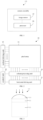
- the disclosure provides a camera assembly 100.
- the camera assembly 100 includes an image sensor 10 and a processor 20.
- the image sensor 10 includes a pixel array 11, the pixel array 11 includes multiple sub-units, each sub-unit includes at least one transparent photosensitive pixel W and at least one color photosensitive pixel, and the color photosensitive pixel has a narrower spectral response range than the transparent photosensitive pixel W.
- the pixel array 11 is exposed to acquire a first color original image and a second color original image, the first color original image is composed of multiple pieces of first color original image data, each piece of the first color original image data is generated by the at least one color photosensitive pixel of the sub-unit, the second color original image is composed of multiple pieces of second color original image data, and each piece of the second color original image data is generated by the at least one transparent photosensitive pixel W and the at least one color photosensitive pixel of the sub-unit.
- the processor 20 is electrically connected to the image sensor 10.
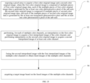
- the processor 20 is configured to perform, for each of multiple color channels, interpolation on the first color original image to acquire a first interpolated image of the color channel, and perform interpolation on the second color original image to acquire a second interpolated image of at least one color channel; fuse the second interpolated image with the first interpolated images of the multiple color channel to obtain fused images of the plurality of color channel; and acquire a target image based on the fused images of the multiple color channels.
- the camera assembly 100 acquires, by exposing the pixel array 11, the first color original image including image data of only monochromatic color channel and the second color original image including image data of both the monochromatic color channel and panchromatic color channel, performs the interpolation on the first color original image to acquire first interpolated images of multiple color channels, performs the interpolation on the second color original image to acquire the second interpolated image of at least one color channel, and fuses the first interpolated image and the second interpolated image to improve the signal-to-noise ratio and the definition of the image so that the quality of the image taken in the dark environment can be improved.
- the camera assembly 100 according to the embodiments of the disclosure will be described in detail below with reference to the drawings.
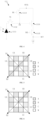
- the image sensor 10 includes a pixel array 11, a vertical driving unit 12 a control unit 13, a column processing unit 14 and a horizontal driving unit 15.
- the image sensor 10 may be adopted with a complementary metal oxide semiconductor (CMOS) photosensitive element or a charge-coupled device (CCD) photosensitive element.
- CMOS complementary metal oxide semiconductor
- CCD charge-coupled device
- the pixel array may include multiple photosensitive pixels 110 (as illustrated in FIG. 3 ) arranged in a two-dimensional array (i.e., arranged in a two-dimensional matrix form), and each photosensitive pixel 110 includes a photoelectric conversion element 1111 (illustrated in FIG. 4 ). Each photosensitive pixel 110 converts light into electric charge according to an intensity of incident light.
- the vertical driving unit 12 includes a shift register and an address decoder.
- the vertical driving unit 12 includes a readout scanning function and a reset scanning function.
- the readout scanning function refers to sequentially scanning unit photosensitive pixels 110 row by row, and reading signals from these unit photosensitive pixels 110 row by row. For example, a signal output by each photosensitive pixel 101 in the selected and scanned photosensitive pixel row is transmitted to the column processing unit 14.
- the reset scanning function is configured to reset the electric charge, and a photo-electron of the photoelectric conversion element 1111 is discarded, such that the accumulation of new photo-electron may be started.
- the signal processing performed by the column processing unit 14 is correlated double sampling (CDS) processing.
- CDS correlated double sampling
- A/D analog-to-digital
- the horizontal driving unit 15 includes a shift register and an address decoder.
- the horizontal driving unit 15 may sequentially scan the two-dimensional pixel array 11 column by column. Through the selection scanning operation performed by the horizontal driving unit 15, each photosensitive pixel column is sequentially processed and output by the column processing unit 14.
- control unit 13 may configure timing signals according to an operation mode, and utilize multiple types of timing signals to control the vertical driving unit 12, the column processing unit 14, and the horizontal driving unit 15 to work together.
- the photosensitive pixel 110 includes a pixel circuit 111, a filter 112, and a microlens 113.
- the microlens 113, the filter 112, and the pixel circuit 111 are arranged in sequence along the light-receiving direction of the photosensitive pixel 110.
- the microlens 113 is configured to condense light
- the filter 112 is configured to pass light of a certain wavelength band and filter out the light of other wavelength bands.
- the pixel circuit 111 is configured to convert the received light into electrical signals, and provide the generated electrical signals to the column processing unit 14 illustrated in FIG. 2 .
- the pixel circuit 111 may be applied to each photosensitive pixel 110 (as illustrated in FIG. 3 ) in the pixel array 11 as illustrated in FIG. 2 .
- the working principle of the pixel circuit 111 will be described below with reference to FIGS. 2 to 4
- the pixel circuit 111 includes a photoelectric conversion element 1111 (e.g., a photodiode), an exposure control circuit (e.g., a transfer transistor 1112), a reset circuit (e.g., reset transistor 1113), an amplifier circuit (e.g., an amplifier transistor 114), and a selection circuit (e.g., a selection transistor 115).
- a photoelectric conversion element 1111 e.g., a photodiode
- an exposure control circuit e.g., a transfer transistor 1112
- a reset circuit e.g., reset transistor 1113
- an amplifier circuit e.g., an amplifier transistor 114
- a selection circuit e.g., a selection transistor 115.
- the transfer transistor 1112, the reset transistor 1113, the amplifier transistor 1114, and the selection transistor 1115 are, for example, MOS transistors, but are not limited thereto.
- the photoelectric conversion element 1111 includes a photodiode, and the anode of the photodiode may be connected to the ground.
- the photodiode converts the received light into an electric charge.
- the cathode of the photodiode is connected to a floating diffusion unit FD through the exposure control circuit (for example, the transfer transistor 1112).
- the FD is connected to the gate of the amplifier transistor 1114 and the source of the reset transistor 1113.
- the exposure control circuit is the transfer transistor 1112, and the control terminal TG of the exposure control circuit is the gate of the transfer transistor 1112.
- a pulse of an active level for example, a VPIX level
- the transfer transistor 1112 is turned on.
- the transfer transistor 1112 transfers the photoconverted charge from the photodiode to the floating diffusion unit FD.
- the drain of the reset transistor 1113 is connected to the pixel power supply (VPIX).
- the source of the reset transistor 113 is connected to the floating diffusion unit FD.
- the pulse of the effective reset level is transmitted to the gate of the reset transistor 113 through a reset line, and the reset transistor 113 is turned on.
- the reset transistor 113 resets the floating diffusion unit FD to the pixel power supply VPIX.
- the gate of the amplifier transistor 1114 is connected to the floating diffusion unit FD.
- the drain of the amplifier transistor 1114 is connected to the pixel power supply VPIX.
- the amplifier transistor 1114 After the floating diffusion unit FD is reset by the reset transistor 1113, the amplifier transistor 1114 outputs a reset level through an output terminal OUT through the selection transistor 1115. After the charge of the photodiode is transferred by the transfer transistor 1112, the amplifier transistor 1114 outputs a signal level through the output terminal OUT of the selection transistor 1115.
- the drain of the selection transistor 1115 is connected to the source of the amplifier transistor 1114.
- the source of the selection transistor 1115 is connected to the column processing unit 114 in FIG. 2 through the output terminal OUT.
- the selection transistor 1115 is turned on.
- the signal output by the amplifier transistor 1114 is transmitted to the column processing unit 14 through the selection transistor 1115.
- the pixel structure of the pixel circuit 111 in the embodiments of the disclosure is not limited to the structure shown in FIG. 4 .
- the pixel circuit 111 may have a three-transistor pixel structure, in which the functions of the amplifier transistor 1114 and the selection transistor 1115 are performed by a transistor.
- the exposure control circuit is not limited to a single transfer transistor 1112, and other electronic elements or structures with the function of controlling the conduction of the control terminal may also be implemented as the exposure control circuit in the embodiments of the disclosure.
- the single transfer transistor 112 according to the embodiments of the disclosure is simple to implement, low cost, and easy to control.
- FIGS. 5 to 15 schematic diagrams of the arrangement of the photosensitive pixels 110 (shown in FIG. 3 ) in the pixel array 11 (shown in FIG. 2 ) according to some embodiments of the disclosure are illustrated.
- the photosensitive pixels 110 include two types, one is a transparent photosensitive pixel W, and the other is a color photosensitive pixel.
- the pixel array 11 includes multiple minimum repeating units, and each minimum repeating unit includes multiple subunits.
- FIGS. 5 to 15 only illustrate the arrangements of multiple photosensitive pixels 110 in one minimum repeating unit composed of four subunits. In other examples, the quantity of the subunits in each minimum repeating unit may also be two, three, five, ten, etc., which is not limited to these examples.
- the pixel array 11 may be formed by duplicating the minimum repeating unit composed of the four subunits, which is illustrated in FIGS. 5 to 17 , multiple times on the rows and columns.
- Each subunit includes at least one transparent photosensitive pixel and at least one color photosensitive pixel.
- the transparent photosensitive pixels W and the color photosensitive pixels may be alternately arranged.
- multiple photosensitive pixels 110 in the same row may have the same color channel.
- multiple photosensitive pixels 110 in the same column may have the same color channel.
- multiple photosensitive pixels 110 in the same row and with the same color channel and multiple photosensitive pixels 110 in the same column and with the same color may be arranged alternatively.
- the transparent photosensitive pixel W may be located at any position in the sub-unit.
- the color photosensitive pixel may be located at any position in the sub-unit.
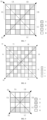
- FIG. 5 is a schematic diagram illustrating an arrangement of photosensitive pixels 110 (as illustrated in FIG. 3 ) in a minimum repeating unit in the pixel array according to some embodiment of the disclosure.
- the minimum repeating unit is composed of 16 photosensitive pixels 110 which are arranged in 4 rows and 4 columns, and each sub-unit is composed of 4 photosensitive pixels 110 arranged in 2 rows and 2 columns.
- the arrangement is: W A W B A W B W W B W C B W C W where W represents the transparent photosensitive pixel W, A represents a first color photosensitive pixel in the multiple color photosensitive pixels, B represents a second color photosensitive pixel in the multiple color photosensitive pixels, and C represents a third color photosensitive pixel in the multiple color photosensitive pixels.
- the transparent photosensitive pixel W and the color photosensitive pixel are arranged alternatively.
- a first type of sub-unit UA includes multiple transparent photosensitive pixels W and multiple first color photosensitive pixels A
- a second type of sub-unit UB includes multiple transparent photosensitive pixels W and multiple second color photosensitive pixels B
- a third type of sub-unit UC includes multiple transparent photosensitive pixels W and multiple third color photosensitive pixels C.
- Each minimum repeating unit includes four subunits, i.e., one first type of sub-unit UA, two second type of sub-units UB, and one third type of sub-unit UC.
- the first type of sub-unit UA and the third type of sub-unit UC are arranged in a first diagonal direction D1 (for example, a direction connecting the upper left corner and the lower right corner in FIG. 5 ), and the two second type of sub-units UB are arranged in a second diagonal direction D2 (for example, a direction connecting the upper right corner and the lower left corner in FIG. 5 ).
- the first diagonal direction D1 is different from the second diagonal direction D2.
- the first diagonal and the second diagonal are perpendicular.
- first diagonal direction D1 may also refer to the direction connecting the upper right corner and the lower left corner
- second diagonal direction D2 may also refer to the direction connecting the upper left corner and the lower right corner
- direction used herein does not refer to a single direction, but may be understood as a concept of a "straight line”, that is, the term “direction” has bidirectional directions between two ends of the straight line.
- the explanation of the first diagonal direction D1 and the second diagonal direction D2 in FIGS. 6 to 10 is the same as the explanation that given here.
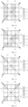
- FIG. 6 is a schematic diagram illustrating another arrangement of photosensitive pixels 110 (as illustrated in FIG. 3 ) in a minimum repeating unit in the pixel array according to some embodiment of the disclosure.
- the minimum repeating unit is composed of 16 photosensitive pixels 110 which are arranged in 4 rows and 4 columns, and each sub-unit is composed of 4 photosensitive pixels 110 arranged in 2 rows and 2 columns.
- the arrangement is: W A W B A W B W B W W C W B C W where W represents the transparent photosensitive pixel W, A represents a first color photosensitive pixel in the multiple color photosensitive pixels, B represents a second color photosensitive pixel in the multiple color photosensitive pixels, and C represents a third color photosensitive pixel in the multiple color photosensitive pixels.
- the arrangement of the photosensitive pixels 110 in the minimum repeating unit illustrated in FIG. 6 is almost the same as the arrangement of the photosensitive pixels 110 in the minimum repeating unit illustrated in FIG. 5 .
- the difference is that the alternating sequence of the transparent photosensitive pixels W and the color photosensitive pixels in the second type of sub-unit UB located in the lower left corner in FIG. 6 is different from the alternating sequence of the transparent photosensitive pixels W and the color photosensitive pixels in the second type of sub-unit UB located in the lower left corner in FIG. 5 .
- the alternating order of the photosensitive pixels 110 in the first row is the transparent photosensitive pixel W and the color photosensitive pixel (i.e., the second color photosensitive pixel B); and the alternating order of the photosensitive pixels 110 in the second row is the color photosensitive pixel (i.e., the second color photosensitive pixel B) and the transparent photosensitive pixel W.
- the alternating order of the photosensitive pixels 110 in the first row is the color photosensitive pixel (i.e., the second color photosensitive pixel B) and the transparent photosensitive pixel W
- the alternating order of the photosensitive pixels 110 in the second row is the transparent photosensitive pixel W, the color photosensitive pixel (i.e., the second color photosensitive pixel B).
- the alternating orders of the transparent photosensitive pixels W and the color photosensitive pixels in the first type of sub-unit UA and the third type of sub-unit UC are different from the alternating order of the transparent photosensitive pixels W and the color photosensitive pixels in the second type of sub-unit UB located in the lower left corner.
- the alternating order of the photosensitive pixels 110 in the first row is the transparent photosensitive pixel W and the color photosensitive pixel
- the alternating order of the photosensitive pixels 110 in the second row is the color photosensitive pixel and the transparent photosensitive pixel W.
- the alternating order of the photosensitive pixels 110 in the first row is the color photosensitive pixel (i.e., the second color photosensitive pixel B) and the transparent photosensitive pixel W
- the alternating order of the photosensitive pixels 110 in the second row is the transparent photosensitive pixel W and the color photosensitive pixel (i.e., the second color photosensitive pixel B).
- the alternating orders of the transparent photosensitive pixels W and the color photosensitive pixels in different sub-units may be the same (as illustrated in FIG. 5 ) or different (as illustrated in FIG. 6 ).
- FIG. 7 is a schematic diagram illustrating still another arrangement of photosensitive pixels 110 (as illustrated in FIG. 3 ) in a minimum repeating unit in the pixel array according to some embodiment of the disclosure.
- the minimum repeating unit is composed of 36 photosensitive pixels 110 which are arranged in 6 rows and 6 columns, and each sub-unit is composed of 9 photosensitive pixels 110 arranged in 3 rows and 3 columns.
- the arrangement is: W A W B W B A W A W B W W W A W B W B B W B W C W W B W C W C B W B W C W
- W represents the transparent photosensitive pixel
- A represents a first color photosensitive pixel in the multiple color photosensitive pixels
- B represents a second color photosensitive pixel in the multiple color photosensitive pixels
- C represents a third color photosensitive pixel in the multiple color photosensitive pixels.
- the transparent photosensitive pixel W and the color photosensitive pixel are arranged alternatively.
- a first type of sub-unit UA includes multiple transparent photosensitive pixels W and multiple first color photosensitive pixels A
- a second type of sub-unit UB includes multiple transparent photosensitive pixels W and multiple second color photosensitive pixels B
- a third type of sub-unit UC includes multiple transparent photosensitive pixels W and multiple third color photosensitive pixels C.
- Each minimum repeating unit includes four subunits, i.e., one first type of sub-unit UA, two second type of sub-units UB, and one third type of sub-unit UC.
- the first type of sub-unit UA and the third type of sub-unit UC are arranged in a first diagonal direction D1
- the two second type of sub-units UB are arranged in a second diagonal direction D2.
- the first diagonal direction D1 is different from the second diagonal direction D2.
- the first diagonal and the second diagonal are perpendicular.
- FIG. 8 is a schematic diagram illustrating yet another arrangement of photosensitive pixels 110 (as illustrated in FIG. 3 ) in a minimum repeating unit in the pixel array according to some embodiment of the disclosure.
- the minimum repeating unit is composed of 64 photosensitive pixels 110 which are arranged in 8 rows and 8 columns, and each sub-unit is composed of 16 photosensitive pixels 110 arranged in 4 rows and 4 columns.
- the arrangement is: W A W A W B W B A W A W B W B W A W A W B W B W A W A W B W B W A W A W B W B W B W A W A W B W B W B W B W C W C W W B W B W B W C W C B W B W C W C W
- W represents the transparent photosensitive pixel
- A represents a first color photosensitive pixel in the multiple color photosensitive pixels
- B represents a second color photosensitive pixel in the multiple color photosensitive pixels
- C represents a third color photosensitive pixel in the multiple color photosensitive pixels.
- the transparent photosensitive pixel W and the color photosensitive pixel are arranged alternatively.
- a first type of sub-unit UA includes multiple transparent photosensitive pixels W and multiple first color photosensitive pixels A
- a second type of sub-unit UB includes multiple transparent photosensitive pixels W and multiple second color photosensitive pixels B
- a third type of sub-unit UC includes multiple transparent photosensitive pixels W and multiple third color photosensitive pixels C.
- Each minimum repeating unit includes four subunits, i.e., one first type of sub-unit UA, two second type of sub-units UB, and one third type of sub-unit UC.
- the first type of sub-unit UA and the third type of sub-unit UC are arranged in a first diagonal direction D1
- the two second type of sub-units UB are arranged in a second diagonal direction D2.
- the first diagonal direction D1 is different from the second diagonal direction D2.
- the first diagonal and the second diagonal are perpendicular.
- FIG. 9 is a schematic diagram illustrating still yet another arrangement of photosensitive pixels 110 (as illustrated in FIG. 3 ) in a minimum repeating unit in the pixel array according to some embodiment of the disclosure.
- the minimum repeating unit is composed of 16 photosensitive pixels 110 which are arranged in 4 rows and 4 columns, and each sub-unit is composed of 4 photosensitive pixels 110 arranged in 2 rows and 2 columns.
- the arrangement is: W W W W A A B B W W W W W B B C C where W represents the transparent photosensitive pixel W, A represents a first color photosensitive pixel in the multiple color photosensitive pixels, B represents a second color photosensitive pixel in the multiple color photosensitive pixels, and C represents a third color photosensitive pixel in the multiple color photosensitive pixels.
- the photosensitive pixels 110 in the same row have the same color channel (that is, the photosensitive pixels 110 in the same row belong to the same type of photosensitive pixels 110.
- the same type of photosensitive pixels 110 includes the following conditions: (1) all the photosensitive pixels 110 are the transparent photosensitive pixel W; (2) all the photosensitive pixels 110 are the first color photosensitive pixel A; (3) all the photosensitive pixels 110 are the second color photosensitive pixel B; (4) all the photosensitive pixels 110 are the third color photosensitive pixel C.
- a first type of sub-unit UA includes multiple transparent photosensitive pixels W and multiple first color photosensitive pixels A; a second type of sub-unit UB includes multiple transparent photosensitive pixels W and multiple second color photosensitive pixels B; and a third type of sub-unit UC includes multiple transparent photosensitive pixels W and multiple third color photosensitive pixels C.
- the multiple photosensitive pixels 110 with the same color channel may be located either in the first row of the sub-unit or in the second row of the sub-unit, which are not limited herein.
- Each minimum repeating unit includes four subunits, i.e., one first type of sub-unit UA, two second type of sub-units UB, and one third type of sub-unit UC.
- the first type of sub-unit UA and the third type of sub-unit UC are arranged in a first diagonal direction D1
- the two second type of sub-units UB are arranged in a second diagonal direction D2.
- the first diagonal direction D1 is different from the second diagonal direction D2.
- the first diagonal and the second diagonal are perpendicular.
- FIG. 10 is a schematic diagram illustrating still yet another arrangement of photosensitive pixels 110 (as illustrated in FIG. 3 ) in a minimum repeating unit in the pixel array according to some embodiment of the disclosure.
- the minimum repeating unit is composed of 16 photosensitive pixels 110 which are arranged in 4 rows and 4 columns, and each sub-unit is composed of 4 photosensitive pixels 110 arranged in 2 rows and 2 columns.
- the arrangement is: A W B W A W B W B W C W B W C W where W represents the transparent photosensitive pixel W, A represents a first color photosensitive pixel in the multiple color photosensitive pixels, B represents a second color photosensitive pixel in the multiple color photosensitive pixels, and C represents a third color photosensitive pixel in the multiple color photosensitive pixels.
- the multiple photosensitive pixels 110 located in the same column have the same color channel (i.e., the multiple photosensitive pixels 110 located in the same column belong to the same type of photosensitive pixel 110).
- the same type of photosensitive pixels 110 includes the following conditions: (1) all the photosensitive pixels 110 are the transparent photosensitive pixel W; (2) all the photosensitive pixels 110 are the first color photosensitive pixel A; (3) all the photosensitive pixels 110 are the second color photosensitive pixel B; (4) all the photosensitive pixels 110 are the third color photosensitive pixel C.
- a first type of sub-unit UA includes multiple transparent photosensitive pixels W and multiple first color photosensitive pixels A; a second type of sub-unit UB includes multiple transparent photosensitive pixels W and multiple second color photosensitive pixels B; and a third type of sub-unit UC includes multiple transparent photosensitive pixels W and multiple third color photosensitive pixels C.
- the multiple photosensitive pixels 110 with the same color channel may be located either in the first column of the sub-unit or in the second column of the sub-unit, which are not limited herein.
- Each minimum repeating unit includes four subunits, i.e., one first type of sub-unit UA, two second type of sub-units UB, and one third type of sub-unit UC.
- the first type of sub-unit UA and the third type of sub-unit UC are arranged in a first diagonal direction D1
- the two second type of sub-units UB are arranged in a second diagonal direction D2.
- the first diagonal direction D1 is different from the second diagonal direction D2.
- the first diagonal and the second diagonal are perpendicular.
- FIG. 11 is a schematic diagram illustrating still yet another arrangement of photosensitive pixels 110 (as illustrated in FIG. 3 ) in a minimum repeating unit in the pixel array according to some embodiment of the disclosure.
- the minimum repeating unit is composed of 16 photosensitive pixels 110 which are arranged in 4 rows and 4 columns, and each sub-unit is composed of 4 photosensitive pixels 110 arranged in 2 rows and 2 columns.
- the arrangement is: A W W W A W B B W W C W B B C W where W represents the transparent photosensitive pixel W, A represents a first color photosensitive pixel in the multiple color photosensitive pixels, B represents a second color photosensitive pixel in the multiple color photosensitive pixels, and C represents a third color photosensitive pixel in the multiple color photosensitive pixels.
- the photosensitive pixels 110 in the same row or the same column have the same color channel (that is, the photosensitive pixels 110 in the same row or in same column belong to the same type of photosensitive pixels 110.
- the same type of photosensitive pixels 110 includes the following conditions: (1) all the photosensitive pixels 110 are the transparent photosensitive pixel W; (2) all the photosensitive pixels 110 are the first color photosensitive pixel A; (3) all the photosensitive pixels 110 are the second color photosensitive pixel B; (4) all the photosensitive pixels 110 are the third color photosensitive pixel C.
- a first type of sub-unit UA includes multiple transparent photosensitive pixels W and multiple first color photosensitive pixels A, the multiple transparent photosensitive pixels W locate in the same column, and the multiple first color photosensitive pixels A locate in the same column.
- a second type of sub-unit UB includes multiple transparent photosensitive pixels W and multiple second color photosensitive pixels B, the multiple transparent photosensitive pixels W locate in the same row, and the multiple second color photosensitive pixels B locates in the same row.
- a third type of sub-unit UC includes multiple transparent photosensitive pixels W and multiple third color photosensitive pixels C, the multiple transparent photosensitive pixels W locates in the same column, and the multiple third color photosensitive pixels C locates in the same column.
- Each minimum repeating unit includes four subunits, i.e., one first type of sub-unit UA, two second type of sub-units UB, and one third type of sub-unit UC.
- the first type of sub-unit UA and the third type of sub-unit UC are arranged in a first diagonal direction D1
- the two second type of sub-units UB are arranged in a second diagonal direction D2.
- the first diagonal direction D1 is different from the second diagonal direction D2.
- the first diagonal and the second diagonal are perpendicular.
- the multiple photosensitive pixels 110 located in the same row in some sub-units belong to the same type of photosensitive pixel 110, and the multiple photosensitive pixels 110 located in the same column in some other sub-units belong to the same type of photosensitive pixel 110.
- FIG. 12 is a schematic diagram illustrating still another arrangement of photosensitive pixels 110 (as illustrated in FIG. 3 ) in a minimum repeating unit in the pixel array according to some embodiment of the disclosure.
- the minimum repeating unit is composed of 16 photosensitive pixels 110 which are arranged in 4 rows and 4 columns, and each sub-unit is composed of 4 photosensitive pixels 110 arranged in 2 rows and 2 columns.
- the arrangement is: A W B W W W W W W B W C W W W W W where W represents the transparent photosensitive pixel W, A represents a first color photosensitive pixel in the multiple color photosensitive pixels, B represents a second color photosensitive pixel in the multiple color photosensitive pixels, and C represents a third color photosensitive pixel in the multiple color photosensitive pixels.
- the color photosensitive pixel may be located at any position in the sub-unit (for example, located at the upper left position of the sub-unit as illustrated in FIG. 12 ).
- a first type of sub-unit UA includes multiple transparent photosensitive pixels W and one first color photosensitive pixel A
- a second type of sub-unit UB includes multiple transparent photosensitive pixels W and one second color photosensitive pixel B
- a third type of sub-unit UC includes multiple transparent photosensitive pixels W and one third color photosensitive pixel C.
- Each minimum repeating unit includes four subunits, i.e., one first type of sub-unit UA, two second type of sub-units UB, and one third type of sub-unit UC.
- the first type of sub-unit UA and the third type of sub-unit UC are arranged in a first diagonal direction D1
- the two second type of sub-units UB are arranged in a second diagonal direction D2.
- the first diagonal direction D1 is different from the second diagonal direction D2.
- the first diagonal and the second diagonal are perpendicular.
- FIG. 13 is a schematic diagram illustrating still another arrangement of photosensitive pixels 110 (as illustrated in FIG. 3 ) in a minimum repeating unit in the pixel array according to some embodiment of the disclosure.
- the minimum repeating unit is composed of 16 photosensitive pixels 110 which are arranged in 4 rows and 4 columns, and each sub-unit is composed of 4 photosensitive pixels 110 arranged in 2 rows and 2 columns.
- the arrangement is: A W W B W W W W W W W W W W W B W W C where W represents the transparent photosensitive pixel W, A represents a first color photosensitive pixel in the multiple color photosensitive pixels, B represents a second color photosensitive pixel in the multiple color photosensitive pixels, and C represents a third color photosensitive pixel in the multiple color photosensitive pixels.
- the color photosensitive pixel may be located at any position in the sub-unit (for example, located at the upper left position, the lower left corner, the upper right corner, or the lower right corner of the sub-unit as illustrated in FIG. 12 ).
- a first type of sub-unit UA includes multiple transparent photosensitive pixels W and one first color photosensitive pixel A
- a second type of sub-unit UB includes multiple transparent photosensitive pixels W and one second color photosensitive pixel B
- a third type of sub-unit UC includes multiple transparent photosensitive pixels W and one third color photosensitive pixel C.
- Each minimum repeating unit includes four subunits, i.e., one first type of sub-unit UA, two second type of sub-units UB, and one third type of sub-unit UC.
- the first type of sub-unit UA and the third type of sub-unit UC are arranged in a first diagonal direction D1
- the two second type of sub-units UB are arranged in a second diagonal direction D2.
- the first diagonal direction D1 is different from the second diagonal direction D2.
- the first diagonal and the second diagonal are perpendicular.
- FIG. 14 is a schematic diagram illustrating still another arrangement of photosensitive pixels 110 (as illustrated in FIG. 3 ) in a minimum repeating unit in the pixel array according to some embodiment of the disclosure.
- the minimum repeating unit is composed of 16 photosensitive pixels 110 which are arranged in 4 rows and 4 columns, and each sub-unit is composed of 4 photosensitive pixels 110 arranged in 2 rows and 2 columns.
- the arrangement is: W A W B A A B B W B W C B B C C where W represents the transparent photosensitive pixel W, A represents a first color photosensitive pixel in the multiple color photosensitive pixels, B represents a second color photosensitive pixel in the multiple color photosensitive pixels, and C represents a third color photosensitive pixel in the multiple color photosensitive pixels.
- the transparent photosensitive pixel W may be located at any position in the sub-unit (for example, located at the upper left position of the sub-unit as illustrated in FIG. 14 ).
- a first type of sub-unit UA includes one transparent photosensitive pixel W and multiple first color photosensitive pixels A
- a second type of sub-unit UB includes one transparent photosensitive pixel W and multiple second color photosensitive pixels B
- a third type of sub-unit UC includes one transparent photosensitive pixel W and multiple third color photosensitive pixels C.
- Each minimum repeating unit includes four subunits, i.e., one first type of sub-unit UA, two second type of sub-units UB, and one third type of sub-unit UC.
- the first type of sub-unit UA and the third type of sub-unit UC are arranged in a first diagonal direction D1
- the two second type of sub-units UB are arranged in a second diagonal direction D2.
- the first diagonal direction D1 is different from the second diagonal direction D2.
- the first diagonal and the second diagonal are perpendicular.
- FIG. 15 is a schematic diagram illustrating still another arrangement of photosensitive pixels 110 (as illustrated in FIG. 3 ) in a minimum repeating unit in the pixel array according to some embodiment of the disclosure.
- the minimum repeating unit is composed of 16 photosensitive pixels 110 which are arranged in 4 rows and 4 columns, and each sub-unit is composed of 4 photosensitive pixels 110 arranged in 2 rows and 2 columns.
- the arrangement is: W A B W A A B B B B C C W B C W where W represents the transparent photosensitive pixel W, A represents a first color photosensitive pixel in the multiple color photosensitive pixels, B represents a second color photosensitive pixel in the multiple color photosensitive pixels, and C represents a third color photosensitive pixel in the multiple color photosensitive pixels.
- the transparent photosensitive pixel W may be located at any position in the sub-unit (for example, located at the upper left position, the lower left position, the upper right position or the lower right position of the sub-unit as illustrated in FIG. 15 ).
- a first type of sub-unit UA includes one transparent photosensitive pixel W and multiple first color photosensitive pixels A
- a second type of sub-unit UB includes one transparent photosensitive pixel W and multiple second color photosensitive pixels B
- a third type of sub-unit UC includes one transparent photosensitive pixel W and multiple third color photosensitive pixels C.
- Each minimum repeating unit includes four subunits, i.e., one first type of sub-unit UA, two second type of sub-units UB, and one third type of sub-unit UC.
- the first type of sub-unit UA and the third type of sub-unit UC are arranged in a first diagonal direction D1
- the two second type of sub-units UB are arranged in a second diagonal direction D2.
- the first diagonal direction D1 is different from the second diagonal direction D2.
- the first diagonal and the second diagonal are perpendicular.
- the first color photosensitive pixel A may be the red photosensitive pixel R; the second color photosensitive pixel B may be a green photosensitive pixel G; and the third color photosensitive pixel C may be the blue photosensitive pixel Bu.
- the first color photosensitive pixel A may be the red photosensitive pixel R; the second color photosensitive pixel B may be a yellow photosensitive pixel Y; and the third color photosensitive pixel C may be the blue photosensitive pixel Bu.
- the first color photosensitive pixel A may be the magenta photosensitive pixel R; the second color photosensitive pixel B may be a cyan photosensitive pixel Cy; and the third color photosensitive pixel C may be the yellow photosensitive pixel Y.
- the response band of the transparent photosensitive pixel W is a visible light band (for example, 400 nm-760 nm).
- the transparent photosensitive pixel W is provided with an infrared filter for filtering out infrared light.
- the response band of the transparent photosensitive pixel W includes the visible light wavelength band and a near-infrared wavelength band (for example, 400 nm-1000 nm), in which the response band matches the response band of the photoelectric conversion element 1111 (as illustrated in FIG. 4 ) in the image sensor 10 (as illustrated in FIG. 1 ).
- the transparent photosensitive pixel W may not be provided with a filter or may be provided with a filter that allows all wavelengths of light to pass through, and the response wavelength band of the transparent photosensitive pixel W is determined based on the response wavelength band of the photoelectric conversion element 1111, that is, the two response wavelength bands are matched.
- the embodiments of the disclosure include, but are not limited to, the above-mentioned waveband ranges.
- the control unit 13 controls the pixel array 11 to be exposed to thereby acquiring a first color original image and a second color original image.
- the first color original image is composed of multiple pieces of first color original image data
- each piece of first color original image data is generated by the at least one color photosensitive pixel of the sub-unit
- the second color original image is composed of multiple pieces of second color original image data
- each piece of second color original image data is generated by the at least one transparent photosensitive pixel and the at least one color photosensitive pixel in the sub-unit.
- each sub-unit of the pixel array 11 includes the multiple transparent photosensitive pixels W and the multiple color photosensitive pixels (as illustrated in FIGS. 5 to 11 ).
- a sum or an average of multiple electrical signals which are generated by the multiple color photosensitive pixels in the sub-unit in response to receiving light, is taken as a piece of the first color original image data, and the multiple pieces of the first color original image data of all sub-units in the pixel array 11 compose the first color original image;
- a sum or an average of multiple electrical signals, which are generated by the multiple transparent photosensitive pixels W and all the multiple color photosensitive pixel in the sub-unit in response to receiving light, is taken as a piece of the second color original image data, and the multiple pieces of the second color original image data of all sub-units in the pixel array 11 compose the second color original image.
- a piece of first color original image data is acquired by calculating a sum or an average of two electrical signals generated by two first color photosensitive pixels A in the first type of sub-unit UA in response to receiving light.
- a piece of first color original image data is acquired by calculating a sum or an average of two electrical signals generated by two second photosensitive pixels B in the second type of sub-unit UB in response to receiving light, thereby acquiring the two pieces of first color original image data.
- a piece of first color original image data is acquired by calculating a sum or an average of two electrical signals generated by two third color photosensitive pixels C in the third type of sub-unit UC in response to receiving light.
- the four pieces of first color original image data together compose a first image unit in the first color original image, and multiple pixels in the first image unit are arranged in the form of ABBC.
- a piece of the second color original image data is acquired by calculating a sum or an average of two electrical signals, which are generated by the two transparent photosensitive pixels W in response to receiving light, and two electrical signals, which are generated by the two first color photosensitive pixels A in response to receiving light.
- a piece of the second color original image data is acquired by calculating a sum or an average of two electrical signals, which are generated by the two transparent photosensitive pixels W in the second type of sub-unit UB in response to receiving light, and two electrical signals, which are generated by the two second color photosensitive pixels B in the second type of sub-unit UB in response to receiving light, thereby acquiring two pieces of the second color original image data.
- a piece of the second color original image data is acquired by calculating a sum or an average of two electrical signals, which are generated by the two transparent photosensitive pixel W in response to receiving the light, and two electrical signals, which are generated by the two third color photosensitive pixels C in response to receiving light.
- the four pieces of the second color original image data together compose a second image unit in the second color original image, and multiple pixels in the second image unit are arranged in the form of ABBC.
- each sub-unit when each sub-unit includes a transparent photosensitive pixel, an electrical signal generated by the transparent photosensitive pixel in response to receiving light is taken as a piece of the first color original image data, and a sum or an average of an electrical signal generated by the color photosensitive pixel in response to receiving light and all electrical signal generated by all the transparent photosensitive pixel in response to receiving light is taken as a piece of the second color original image data.
- each sub-unit when each sub-unit includes a transparent photosensitive pixel W, a sum or an average of an electrical signal generated by the transparent photosensitive pixel W in response to receiving light and all electrical signal generated by all the color photosensitive pixel in the sub-unit in response to receiving light is taken as a piece of the second color original image data.
- the image sensor 10 after acquiring the first color original image and the second color original image, the image sensor 10 performs, for each color channel, the interpolation on the first color original image to acquire the first interpolated image of the color channel, and performs the interpolation on the second color original image to acquire the second interpolated image of at least one color channel.
- a reference area 112 for the interpolation processing of the first color original image may be an area of size 7 ⁇ 7 (as illustrated in FIG. 17 ), where A represents the first color photosensitive pixel in the first color original image; B represents the second color photosensitive pixel in the first color original image; C represents the third color photosensitive pixel in the first color original image.
- a demosaicing algorithm may be used to perform the interpolation on the first color original image to thereby acquire the first interpolated image of the second color channel.
- the image data of the second color channel of the pixel in the first color original image is taken as image data of the second color channel of the pixel in the first interpolated image.
- B 12' B 12.
- the interpolation is performed on a pixel C44 in the first color original image that has the image data of the third color channel, and a missed second color photosensitive pixel B44' corresponding to the C44 may be acquired through the following two equations, and the missed pixel is filled by the interpolation to obtain the first interpolated image of the second color channel.
- the missed second color photosensitive pixel B44' corresponding to C44 may be acquired through the two equations.
- B 44 ′ ⁇ 34 B ⁇ 34 + ⁇ 43 B ⁇ 43 + ⁇ 45 B ⁇ 45 + ⁇ 54
- the interpolation which is performed on the pixel in the first color original image that has the image data of the first color channel to acquire the first interpolated image of the second color channel, is similar to the interpolation that is performed on the pixel having the image data of the third color channel to acquire the first interpolated image of the second color channel. Details are not repeated herein.
- a reference area 113 for the interpolation processing of the first color original image may be an area of size 7 ⁇ 7 (as illustrated in FIG. 18 ), where A represents the first color photosensitive pixel in the first color original image; B represents the second color photosensitive pixel in the first color original image; C represents the third color photosensitive pixel in the first color original image.
- the demosaicing algorithm may be used to perform the interpolation on the first color original image to thereby acquire a first interpolated image of the first color channel.
- the image data of the first color channel of the pixel in the first color original image is taken as the image data of the corresponding pixel in the first interpolated image of the first color channel.
- A11' A11. It requires performing the interpolation, when the pixel in the first color original image has image data of the third color channel.
- the interpolation is performed on a pixel C44, and a missed second color photosensitive pixel A44' corresponding to the C44 may be acquired through the following two equations, and the missed pixel is filled by the interpolation to obtain the first interpolated image of the first color channel.
- image data of pixels B33', B35', B44', B53' and B55' may be acquired according to the calculation manner illustrated in FIG. 17 .
- a ⁇ 33 A 33 + B 44 ′ ⁇ B 33 ′ 2
- a ⁇ 35 A 35 + B 44 ′ ⁇ B 35 ′ 2
- a ⁇ 53 A 53 + B 44 ′ ⁇ B 53 ′ 2
- a ⁇ 55 A 55 + B 44 ′ ⁇ B 55 ′ 2
- 53 1 1 + B 44 ′ ⁇ B 53 ′ + C 44 ⁇ C 62 2
- 55 1 1 + B 44 ′ ⁇ B 55 ′ + C 44 ⁇ C 66 2
- a 44 ′ ⁇ 33 A ⁇ 34 + ⁇ 35 A ⁇ 35 + ⁇ 53 A ⁇ 53 + ⁇ 55 A ⁇ 55 ⁇ 33 + ⁇ 35 + ⁇ 53 + ⁇ 55
- the interpolation is performed on the first color original image to acquire the first interpolated image of the first color channel. It requires to perform the interpolation, when the pixel in the first color original image has image data of the second color channel.
- the interpolation is performed on a pixel B34, and a missed first color photosensitive pixel A34' corresponding to the B34 may be acquired through the following two equations, and the missed pixel is filled by the interpolation to obtain the first interpolated image of the first color channel.
- a ⁇ 33 A 33 + B 34 ⁇ B 31 2
- a ⁇ 35 A 35 + B 34 ⁇ B 36 2
- a 34 ′ ⁇ 33 A ⁇ 33 + ⁇ 35 A ⁇ 35 ⁇ 33 + ⁇ 35
- the interpolation which is weighted with both left and right directions, is performed on the pixel in the first color original image that has the image data of the second color channel to acquire the interpolated image of the first color channel.
- the interpolation direction of the missed first color photosensitive A34' corresponding to the B34 is to perform the weighting with both the left and right directions.
- the interpolation, which is weighted by both up and down directions is performed on the pixel in the first color original image that has the image data of the second color channel to acquire the interpolated image of the first color channel.
- the interpolation direction for calculating the missed first color photosensitive A45' corresponding to the B45 is to weight with both up and down directions.
- the calculation method of weighting with the left and right directions is similar to the calculation method of weighting with the upper and lower directions, and details are not described here.
- the demosaicing algorithm may be used to perform the interpolation on the first color original image to thereby acquire a first interpolated image of the third color channel.
- the image data of the third color channel of the pixel in the third color original image is taken as image data of a pixel in the first interpolated image of the third color channel. It requires to perform the interpolation when the pixel in the first color original image has the data map of the first color channel or the second color channel.
- the interpolation which is performed on the pixel in the first color original image that has the image data of the first color channel to acquire the first interpolated image of the third color channel, is similar to the interpolation that is performed on the pixel having the image data of the third color channel to acquire the first interpolated image of the first color channel. Details are not repeated herein.
- the interpolation is performed on the pixel in the first color original image that having the image data of the second color channel, so as to acquire the first interpolated image of the third color channel, which is similar to the interpolation that is performed on the pixel having the image data of the second color channel to acquire the first interpolated image of the first color channel. Details are not repeated herein.
- the processor 20 may adopt the demosaicing algorithm to perform the interpolation on the second color original image, so as to acquire a second interpolated image of at least one color channel.
- the processor 20 performs the interpolation on the second color original image in a manner similar to the embodiment illustrated in FIGS. 17 and 18 to obtain the second interpolated image of the first color channel, the second interpolated image of the second color channel, and the second interpolated image of the second color channel. Details will not be described here.
- the interpolation method of the first color original image and the second color original image may also be other commonly used demosaicing algorithms, such as nearest neighbor interpolation, linear interpolation, cubic interpolation, high-quality linear interpolation method, smooth hue transition interpolation, pattern recognition interpolation, adaptive color plane interpolation, interpolation algorithm based on orientated weighted gradient, etc.
- the image sensor 10 fuses, for each color channel, the second interpolated image with the first interpolated image of the color channel to obtain a fused image of the color channel, thereby obtaining the fused images of the multiple color channels.
- the second interpolated image of the second color channel is fused with the first interpolated image of each color channel to obtain the fused image of each color channel.
- the second interpolated image of the second color channel is fused with the first interpolated image of the first color channel to obtain the fused image of the first color channel.
- the second interpolated image of the second color channel is fused with the first interpolated image of the second color channel to obtain the fused image of the second color channel.
- the second interpolated image of the second color channel is fused with the first interpolated image of the third color channel to obtain the fused image of the third color channel.
- a target image is obtained based on the fused images of the multiple color channel.
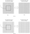
- the first interpolated image of the multiple color channel and the second interpolated image of the at least one color channel may be processed by the operation as follows. Specifically, the processor 20 may filter, for each of the multiple color channels, the first interpolated image of the color channel to obtain a first filtered image of the color channel; and the first filtered image is composed of multiple pieces of first filtered image data. Specifically, the processor 20 may filter the second interpolated image of the at least one color channel to obtain a second filtered image; and the second filtered image is composed of multiple pieces of second filtered image data.
- the processor may filter the first interpolated image of each color channel to obtain the first filtered image of each color channel in a manner as follows. Specifically, the processor 20 may determine a first to-be-filtered pixel and a first to-be-filtered area in the first interpolated image of the first color channel, and the first to-be-filtered pixel is located in the first to-be-filtered area. The processor 20 may determine a first reference pixel and a first reference area in the second interpolated image, where the first reference pixel corresponds to the first to-be-filtered pixel, and the first reference area corresponds to the first to-be-filtered area. For example, with regard to the processor 20 filtering the first interpolated image of the first color channel (as illustrated in FIG.
- the processor 20 determines a pixel A44' as the first to-be-filtered pixel, and then the processor 20 may determine the first to-be-filtered area 116 according to the first to-be-filtered pixel A44', and then the processor 20 may determine the first reference pixel B'44' and the first reference area 119 in the second interpolated image, in which the first reference pixel B'44' corresponds to the first to-be-filtered pixel A44', and the first reference area 119 corresponds to the first to-be-filtered area 116 of the first color channel.
- the first to-be-filtered pixel A44' of the first color channel may be located at any position in the first to-be-filtered area 116 of the first color channel; a shape of a window formed by the first reference area 119 may be a square, or other shapes such as a rectangle, which is not limited thereto.
- the size of the first reference area 119 may be 3x3, 4x4, 5x5, 3x5, 5x7, 7x7, or 9x5, etc., which is not limited thereto.
- the first reference area 119 is an area of size 3 ⁇ 3.
- Multiple first pixels in the first reference area 119 include B'33', B'34', B'35', B'43', B'44', B'45', B'53', B'54' and B'55'.
- the processor 20 calculates a weight for the first pixel relative to the first reference pixel B'44', and the weight includes a weight in a spatial domain and a weight in a range domain.
- a pixel value of the first to-be-filtered pixel of the first color channel is corrected to obtain one piece of the first filtered image data of the first color channel, according to the weights for the multiple first pixels, i.e., B'33', B'34', B'35', B'43', B'44', B'45', B'53', B'54' and B'55, and pixel values of pixels corresponding to the first to-be-filtered area 116 of the first color channel.
- the processor 20 may calculate the weights in the spatial domain for the multiple first pixels, i.e., B'33', B'34', B'35', B'43', B'44', B'45', B'53', B'54' and B'55', relative to the first reference pixel B'44' according to a weight function f( ⁇ p - q ⁇ ), where p represents the coordinates of the first reference pixel B'44' in the first reference area 119, q represents the coordinates of the multiple first pixels, i.e., B'33', B'34', B'35', B'43', B'44', B'45', B'53', B'54', in the first reference area 119, and f represents the weight function in the spatial domain.
- the processor 20 may calculate the weights in the range domain for the multiple first pixels, i.e., B'33', B'34', B'35', B'43', B'44', B'45', B'53', B'54' and B'55', relative to the first reference pixel B'44' according to a weight function g( ⁇ p - ⁇ q ⁇ ), where ⁇ p represents first interpolated image data (may also be understood as a pixel value) of the first reference pixel B'44' in the first reference area 119, and ⁇ q represents first interpolated image data (may also be understood as pixel values) of the multiple first pixels, i.e., B'33', B'34', B'35', B'43', B'44', B'45', B'53', B'54', in the first reference area 119, and g represents the weight function in the range domain. Specifically, for each of the multiple first pixels, the larger the difference between the
- the processor 20 may correct, according to the weights for the multiple first pixels and the pixel values of pixels corresponding to the first to-be-filtered area of the first color channel, a pixel value of the first to-be-filtered pixel of the first color channel to obtain one piece of the first filtered image data of the first color channel.
- the processor 20 may acquire the first filtered image data, i.e., A33", A34", A35", A43", A44", A45", A53", A54", and A55" of respective first to-be-filtered pixels, i.e., A33', A34', A35', A43', A44', A45', A53', A54', and A55', in the first to-be-filtered area 116.
- the processor 20 may traverse each pixel in the first interpolated image of the first color channel to obtain the multiple pieces of first filtered image data of the first color channel.
- the processor 20 may determine each pixel in the first interpolated image of the first color channel as the first to-be-filtered pixel and filter each pixel in a manner of the embodiments illustrated in FIG. 20 , thereby obtaining the first filtered image data of the first color channel corresponding to the pixel. After acquiring the multiple pieces of the first filtered image data of the first color channel, the multiple pieces of the first filtered image data of the first color channel may compose the first filtered image of the first color channel.
- the first filtered images of the multiple color channels are obtained by filtering the first interpolated images of the multiple color channels, respectively.
- the first filtered image is composed of multiple pieces of first filtered image data
- the first filtered image data may be obtained by performing the correction based on the weights for the first pixels in the second interpolated image and the pixel values of the pixels corresponding to the first to-be-filtered area.
- the second interpolated image is acquired by performing the interpolation on the second color original image having the transparent photosensitive pixel W and at least one color channel.
- the weights for the first pixels in the second interpolated image are used to filter the first interpolated image of each color channel, which can make the first filtered image of each color channel have high light intake and sharpness, while the first filtered image data can be calculated precise.
- the processor 20 may also filter the first interpolated image of the second color channel.
- the processor 20 takes the pixel B44' as a first to-be-filtered pixel, and the processor 20 may determine a first to-be-filtered area 117 (as illustrated in FIG. 21 ) of the second color channel according to the first to-be-filtered pixel B44'.
- the processor 20 may determine a first reference pixel B'44' and a first reference area 119 in the second interpolated image.
- the first reference pixel B'44' corresponds to the first to-be-filtered pixel B44' of the second color channel; and the first reference area 119 corresponds to the first to-be-filtered area 117 of the second color channel.
- the processor 20 calculates a weight for the first pixel relative to the first reference pixel B'44', and the weight includes a weight in a spatial domain and a weight in a range domain.
- a pixel value of the first to-be-filtered pixel of the second color channel is corrected to obtain a piece of the first filtered image data of the second color channel, according to the weights for the multiple first pixels and pixel values of pixels corresponding to the first to-be-filtered area 117 of the second color channel.
- the processor may filter the first interpolated image of the second color channel to obtain a first filtered image of the second color channel like the embodiments illustrated in FIG. 20 . Details are not described here.
- the processor 20 may also filter the first interpolated image of the third color channel.
- the processor 20 takes a pixel C44' as a first to-be-filtered pixel, and the processor 20 may determine a first to-be-filtered area 118 (as illustrated in FIG. 22 ) of the third color channel according to the first to-be-filtered pixel C44'.
- the processor may determine a first reference pixel B'44' and a first reference area 119 in the second interpolated image, in which the first reference pixel B'44' corresponds to the first to-be-filtered pixel C44' of the third color channel, and the first reference area 119 corresponds to the first to-be-filtered area of the third color channel.
- Multiple first pixels in the first reference area 119 include B'33', B'34', B'35', B'43', B'44', B'45', B'53', B'54' and B'55'.
- the processor 20 calculates weights for the first pixel relative to the first reference pixel B'44', and the weight includes the weight in a spatial domain and the weight in a range domain.
- a pixel value of the first to-be-filtered pixel of the third color channel is corrected to obtain a piece of the first filtered image data of the third color channel, according to the weights for the multiple first pixels, and pixel values of pixels corresponding to the first to-be-filtered area 118 of the third color channel.
- the processor 20 may filter the first interpolated image of the third color channel to obtain a first filtered image of the third color channel like the embodiments illustrated in FIG. 20 . Details are not described here.
- the second filtered image is composed of multiple pieces of second filtered image data, and the second interpolated image is filtered to obtain the second filtered image.
- the processor 20 may determine a second to-be-filtered pixel and a second to-be-filtered area in the second interpolated image, and the second to-be-filtered pixel is located in the second to-be-filtered area. For each of the multiple second pixels in the second to-be-filtered area, the processor 20 may calculate a weight for the second pixel relative to the second to-be-filtered pixel, and the weight includes a weight in a spatial domain and a weight in a range domain.
- the processor 20 may correct, according to the pixel values of the multiple second pixels and the weights for the multiple second pixels, pixel values of the second to-be-filtered pixels to obtain a piece of the second filtered image data.
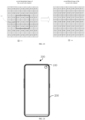
- the processor 20 may traverse each pixel in the second interpolated image to obtain the multiple pieces of second filtered image data. For example, the processor 20 filters the second interpolated image of the second color channel (as illustrated in FIG. 23 ), the processor 20 may determine a pixel B'44' in the second interpolated image of the second color channel as the second to-be-filtered pixel of the second color channel, and then the processor 20 may determine the second to-be-filtered area 12 of the second color channel according to the second to-be-filtered pixel B'44' of the second color channel.
- the second to-be-filtered pixel B'44' of the second color channel may be located anywhere in the second to-be-filtered area 119 of the second color channel.
- a shape of a window formed by the second to-be-filtered area 119 of the second color channel may be a square, or other shapes such as a rectangle, which are not limited thereto.
- the size of the second to-be-filtered area 119 may be 3x3, 4x4, 5x5, 3x5, 5x7, 7x7, or 9x5, etc., which is not limited thereto.
- the second to-be-filtered area 119 of the second color channel is an area of size 3 ⁇ 3.
- the multiple second reference pixels of the second color channel in the second to-be-filtered area 119 of the second color channel further include: B'33', B'34', B'35', B'43', B'44', B'45', B'53', B'54' and B'55'.
- the processor 20 calculates a weight for the second reference pixel relative to the second to-be-filtered pixel B'44' of the second color channel, in which the weight includes a weight in a spatial domain and a weight in a range domain.
- the processor 20 may calculate the weights in the spatial domain of the multiple second reference pixels, i.e., B'33', B'34', B'35', B'43', B'44', B'45', B'53', B'54' and B'55', of the second color channel relative to the second to-be-filtered pixel of the second color channel B'44' according to a weight function f( ⁇ p - q ⁇ ), where p represents the coordinates of the second to-be-filtered pixel B'44' in the second to-be-filtered area 119 of the second color channel, and q represents the coordinates of the multiple second reference pixels, i.e., B'33', B'34', B'35', B'43', B'44', B'45', B'53', B'54', of the second color channel in the second to-be-filtered pixel area 119, and f represents the weight function in the spatial domain.
- the processor 20 may calculate the weights in the spatial domain for the multiple second reference pixels , i.e., B'33', B'34', B'35', B'43', B'44', B'45', B'53', B'54' and B'55', of the second color channel relative to the second to-be-filtered pixel B'44' of the second color channel according to a weight function g( ⁇ p - ⁇ q ⁇ ), where ⁇ p represents second interpolated image data (may also be understood as a pixel value) of the second to-be-filtered pixel B'44' of the second color channel, ⁇ q represents second interpolated image data (may also be understood as pixel values) of the multiple second reference pixels , i.e., B'33', B'34', B'35', B'43', B'44', B'45', B'53', B'54' and B'55', of the second color channel and g represents the weight function in
- the processor may correct, according to the pixel values and the weights for the multiple second reference pixels of the second color, the pixel value of the second to-be-filtered pixel to obtain one of the multiple pieces of the second filtered image data of the second color channel.
- the processor 20 may traverse each pixel in the second interpolated image of the second color channel to obtain the multiple pieces of the second filtered image data of the second color channels, and the processor 20 may compose the multiple pieces of the second filtered image data of multiple second color channels into the second filtered image of the second color channel.
- the processor 20 may also filter the second interpolated image of the first color channel and the second interpolated image of the third color channel to obtain the second filtered image of the first color channel and the second filtered image of the third color channel respectively, in a manner similar to the embodiments illustrated in FIG. 23 . Details are not described here.
- the flat area in the filtered image is smooth, while protecting the edge area in the filtered image from being blurred and therefore be prominent, which is conducive to improving the imaging quality of the camera assembly 100 (illustrated in FIG. 1 ).
- the processor 20 may further fuse the second filtered image with the first filtered images of the multiple color channels to obtain fused images of the multiple color channels, in which the fused image is composed of multiple pieces of fused image data.
- the processor may obtain one of the multiple pieces of fused image data by performing a calculation according to one of the multiple pieces of the first filtered image data, one of the multiple pieces of the second filtered image, and one of the multiple pieces of the interpolated image data. Specifically, the fused image data is positively correlated with the first filtered image data, the fused image data is negatively correlated with the second filtered image data, and the fused image data is positively correlated with the interpolated image data.
- the processor 20 may traverse each pixel in the first filtered image to acquire the multiple pieces of fused image data.
- b 1 represents image data of a preset pixel in the second interpolated image of the second color channel
- a represents image data of a pixel corresponding to the preset pixel in the first filtered image of the first color channel
- b represents image data of a pixel corresponding to the preset pixel in the first filtered image of the second color channel
- c represents image data of a pixel corresponding to the preset pixel in the first filtered image of the third color channel
- b 2 represents the second filtered image data of the second color channel.
- the fused image data of the first color channel is ab 1 /b 2
- the fused image data of the second color channel is bb 1 /b 2
- the fused image data of the third color channel is cb 1 /b 2 .
- a 1 represents image data of a preset pixel in the second interpolated image of the first color channel
- b 1 represents image data of the preset pixel in the second interpolated image of the second color channel
- c 1 represents image data of the preset pixel in the second interpolated image of the third color channel
- a represents image data of a pixel corresponding to the preset pixel in the first filtered image of the first color channel
- b represents image data of a pixel corresponding to the preset pixel in the first filtered image of the second color
- c represents image data of a pixel corresponding to the preset pixel in the first filtered image of the third color channel
- a 2 represents the second filtered image data of the first color channel
- b 2 represents the second filtered image data of the second color channel
- c 2 represents the second filtered image data of the third color channel.
- the fused image data of the first color channel is aa 1 /a 2
- the fused image data of the second color channel is bb 1 /b 2
- the fused image data of the third color channel is cc 1 /c 2 .
- the processor 20 may determine the first filtered image data as the fused image data.
- the processor 20 may obtain the fused image data by performing the calculation according to the first filtered image data, the second filtered image, and the interpolated image data. Specifically, the fused image data is positively correlated with the first filtered image data, the fused image data is negatively correlated with the second filtered image data, and the fused image data is positively correlated with the interpolated image data.
- the processor 20 may set the preset pixel value to 959.
- the processor 20 When the first filtered image data is greater than the preset pixel value of 959, it is determined that the first filtered image data is in an overexposed state, and the processor 20 does not fuse the first filtered image data, and determines the first filtered image data as the fused image data. When the first filtered image data is less than the preset pixel value of 959, the processor 20 performs the calculation according to the first filtered image data, the second filtered image data, and the interpolated image data, so as to obtain the fused image data.
- the fused images of the multiple color channels may be directly converted into a YUV image, and the YUV image is taken as the target image.
- the pixels in the fused image of each color channel may be taken to form the target image of the Bayer array, and then the target image is transmitted to the image processor (ISP) for processing.
- the processor 20 may include a processing circuit and the ISP.
- the processing circuit is integrated in the image sensor 10 and configured to implement the image acquisition method according to the embodiments of the disclosure. After the target image is obtained, the target image is transmitted to the ISP for performing subsequent image processing thereon.
- the target image is obtained from the fused images of the multiple color channel through performing the interpolation, the filtering and the fusing on the first color original image and the second color original image.
- the target image is fused with the transparent photosensitive pixel W with large light intake, so that the target image has high signal-to-noise ratio and clarity.
- the first color original image inherits the high signal-to-noise ratio and clarity of the second color original image using fusion, which can improve the effect of taking pictures at night and the quality of the image.
- the camera assembly 100 obtains, by exposing the pixel array 11, the first color original image including image data of only monochromatic color channel and the second color original image including image data of both the monochromatic color channel and panchromatic color channel, the camera assembly 100 performs the interpolation, the filtering and the fusing on the first color original image and the second color original image, to improve the signal-to-noise ratio and the clarity of the image by using the image data of the panchromatic color channel, so that the quality of the image taken in the dark environment can be improved, the flat area in the image is smooth, and the edge area in the image is prominent to further improve the quality of the image.
- the disclosure further provides a mobile terminal 300.
- the mobile terminal 300 includes the camera assembly 100 described in any one of the foregoing embodiments and a housing 200.
- the camera assembly 100 is combined with the housing 200.
- the mobile terminal 300 may be a mobile phone, a tablet computer, a notebook computer, a smart wearable device (e.g., a smart watch, a smart bracelet, smart glasses, a smart helmet), a drone, a head-mounted display device, etc., which are not limited thereto.
- a smart wearable device e.g., a smart watch, a smart bracelet, smart glasses, a smart helmet
- a drone e.g., a head-mounted display device, etc., which are not limited thereto.
- the mobile terminal 300 obtains, by exposing the pixel array 11, the first color original image including image data of only a monochromatic color channel and the second color original image including image data of both monochromatic color channel and the panchromatic color channel, and fuses the first color original image and the second color original image to improve the signal-to-noise ratio and the clarity of the image by using the image data of the panchromatic color channel, so that the quality of the image taken in the dark environment can be improved.
- the disclosure further provides an image acquisition method that may be applied to the image sensor 10 described in any one of the above embodiments.
- the image acquisition method includes operations as follows.
- At 01 exposing a pixel array 11 to acquire a first color original image and a second color original image, where the first color original image is composed of multiple pieces of first color original image data, each of the multiple pieces of first color original image data is generated by the at least one color photosensitive pixel of the sub-unit, the second color original image is composed of multiple pieces of second color original image data, and each of the multiple pieces of second color original image data is generated by the at least one transparent photosensitive pixel and the at least one color photosensitive pixel of the sub-unit.
- At 02 performing, for each of multiple color channels, an interpolation on the first color original image to acquire a first interpolated image of the color channel, and performing interpolation on the second color original image to acquire a second interpolated image of at least one color channel.
- At 03 fusing the second interpolated image with the first interpolated images of the plurality of color channels to obtain fused images of the plurality of color channels.
- At 04 acquiring a target image based on the fused images of the multiple color channels.
- the acquisition method further includes:
- the operation 04 of acquiring the target image based on the fused images of the multiple color channels includes: fusing the second filtered image with the first filtered image of the multiple color channels to obtain the fused images of the multiple color channels.
- the operation of filtering, for each of the multiple color channels, the first interpolated image of the color channel to obtain a first filtered image of the color channel includes:
- the operation of filtering the second interpolated image to obtain a second filtered image includes:
- the operation of fusing the second filtered image with the first filtered images of the multiple color channels to obtain the fused images of the multiple color channels includes:
- the operation of fusing the second filtered image with the first filtered images of the multiple color channels to obtain the fused images of the multiple color channels further includes:
- each of the multiple the sub-unit includes multiple the color photosensitive pixels
- a sum or an average of multiple electrical signals generated by the multiple color photosensitive pixels after receiving light are taken as a piece of the first color original image data
- each sub-unit when each sub-unit includes one the transparent photosensitive pixel W, a sum or an average of an electrical signal generated by the transparent photosensitive pixel W after receiving light and all electrical signal generated by all the color photosensitive pixel in the sub-unit after receiving light is taken as a piece of the second color original image data.
- each sub-unit when each sub-unit includes multiple the transparent photosensitive pixels, a sum or average of multiple electrical signals generated by the multiple transparent photosensitive pixels after receiving light and all electrical signal generated by all the color photosensitive pixel in the sub-unit is taken as a piece of the second color original image data.
- the specific implementation process of the image acquisition method described in any one of the above embodiments is the same as that described above for acquiring the first color original image and the second color original image of the camera assembly 100 (shown in FIG. 1 ) and interpolating the first color original image and the second color original image to obtain the first interpolated image of each color channel and the second interpolated image of at least one color channel, fusing the second interpolated image with the first interpolated image of each color channel to obtain the fused image of each color channel, and obtaining the target image based on the fused image of each color channel.
- the invention is defined by the appended claims.
Landscapes
- Engineering & Computer Science (AREA)
- Multimedia (AREA)
- Signal Processing (AREA)
- Physics & Mathematics (AREA)
- Spectroscopy & Molecular Physics (AREA)
- General Physics & Mathematics (AREA)
- Theoretical Computer Science (AREA)
- Color Television Image Signal Generators (AREA)
Claims (15)
- Procédé d'acquisition d'images, réalisé par un ensemble caméra (100) comprenant un capteur d'images (10) et un processeur (20), le capteur d'images (10) comprenant une matrice de pixels (11) comportant une pluralité de sous-unités (UA, UB, UC), chacune de la pluralité de sous-unités (UA, UB, UC) comprenant au moins un pixel photosensible transparent (W) et au moins un pixel photosensible couleur (A, B, C), et le pixel photosensible couleur (A, B, C) possédant une plage de réponse spectrale plus étroite que celle du pixel photosensible transparent (W) ; le procédé d'acquisition d'images comprenant :l'acquisition (01) d'une première image couleur initiale et d'une deuxième image couleur initiale par exposition de la matrice de pixels (11), la première image couleur initiale étant composée d'une pluralité d'éléments de données de première image couleur initiale, chacun de la pluralité d'éléments de données de première image couleur initiale étant généré par l'au moins un pixel photosensible couleur (A, B, C) de la sous-unité (UA, UB, UC), la deuxième image couleur initiale étant composée d'une pluralité d'éléments de données de deuxième image couleur initiale ;le procédé étant caractérisé en ce que,chacun de la pluralité d'éléments de données de deuxième image couleur initiale est généré par l'au moins un pixel photosensible transparent (W) et l'au moins un pixel photosensible couleur (A, B, C) de la sous-unité (UA, UB, UC) ; eten ce qu'il comprend en outre :la réalisation (02), pour chacun d'une pluralité de canaux de couleur, d'une interpolation sur la première image couleur initiale dans le but d'acquérir une première image interpolée du canal de couleur, et la réalisation, pour au moins un de la pluralité de canaux de couleur, d'une interpolation sur la deuxième image couleur initiale dans le but d'acquérir une deuxième image interpolée de l'au moins un canal de couleur, la pluralité de canaux de couleur comprenant un premier canal de couleur, un deuxième canal de couleur et un troisième canal de couleur ;la fusion (03) de la deuxième image interpolée de l'au moins un canal de couleur avec les premières images interpolées de la pluralité de canaux de couleur dans le but d'obtenir des images fusionnées de la pluralité de canaux de couleur ; etl'acquisition (04) d'une image cible sur la base des images fusionnées de la pluralité de canaux de couleur.
- Procédé d'acquisition d'images selon la revendication 1, comprenant en outre :le filtrage, pour chacun de la pluralité de canaux de couleur, de la première image interpolée du canal de couleur dans le but d'obtenir une première image filtrée du canal de couleur ; etle filtrage de la deuxième image interpolée de l'au moins un canal de couleur dans le but d'obtenir une deuxième image filtrée de l'au moins un canal de couleur ; etdans lequel la fusion (03) de la deuxième image interpolée de l'au moins un canal de couleur avec les premières images interpolées de la pluralité de canaux de couleur dans le but d'obtenir des images fusionnées de la pluralité de canaux de couleur comprend :
la fusion de la deuxième image filtrée de l'au moins un canal de couleur avec la première image filtrée de la pluralité de canaux de couleur dans le but d'obtenir les images fusionnées de la pluralité de canaux de couleur. - Procédé d'acquisition d'images selon la revendication 2, dans lequel la première image filtrée est composée d'une pluralité d'éléments de données de première image filtrée, et le filtrage, pour chacun de la pluralité de canaux de couleur, de la première image interpolée du canal de couleur dans le but d'obtenir une première image filtrée du canal de couleur comprend :la détermination d'un premier pixel à filtrer et d'une première région à filtrer (116, 117, 118) dans la première image interpolée, le premier pixel à filtrer étant situé dans la première région à filtrer (116, 117, 118) ;la détermination d'un premier pixel de référence et d'une première région de référence (119) dans la deuxième image interpolée, le premier pixel de référence correspondant au premier pixel à filtrer, et la première région de référence (119) correspondant à la première région à filtrer (116, 117, 118) ;le calcul, pour chacun d'une pluralité de premiers pixels dans la première région de référence (119), d'un poids pour le premier pixel par rapport au premier pixel de référence, et le poids comprenant un poids dans un domaine spatial et un poids dans un domaine de plage ;la correction, selon les poids de la pluralité de premiers pixels et des valeurs de pixel de pixels correspondant à la première région à filtrer (116, 117, 118), d'une valeur de pixel du premier pixel à filtrer dans le but d'obtenir l'un de la pluralité d'éléments de données de première image filtrée ; etla traversée de chaque pixel dans la première image interpolée dans le but d'obtenir la pluralité d'éléments de données de première image filtrée.
- Procédé d'acquisition d'images selon la revendication 2 ou la revendication 3, dans lequel la deuxième image filtrée est composée d'une pluralité d'éléments de données de deuxième image filtrée, et le filtrage de la deuxième image interpolée dans le but d'obtenir la deuxième image filtrée comprend :la détermination d'un deuxième pixel à filtrer dans la deuxième image interpolée ;la détermination d'une deuxième région à filtrer (119) dans la deuxième image interpolée, le deuxième pixel à filtrer étant situé dans la deuxième région à filtrer (119) ;le calcul, pour chacun d'une pluralité de deuxièmes pixels dans la deuxième région à filtrer (119), d'un poids pour le deuxième pixel par rapport au deuxième pixel à filtrer, et le poids comprenant un poids dans un domaine spatial et un poids dans un domaine de plage ;la correction, selon des valeurs de pixel de la pluralité de deuxièmes pixels et les poids de la pluralité de deuxièmes pixels, d'une valeur de pixel du deuxième pixel à filtrer dans le but d'obtenir l'un de la pluralité d'éléments de données de deuxième image filtrée ; etla traversée de chaque pixel dans la deuxième image interpolée dans le but d'obtenir la pluralité d'éléments de données de deuxième image filtrée.
- Procédé d'acquisition d'images selon l'une quelconque des revendications 2 à 4, dans lequel la première image filtrée est composée d'une pluralité d'éléments de données de première image filtrée, la deuxième image filtrée est composée d'une pluralité d'éléments de données de deuxième image filtrée, la deuxième image interpolée est composée d'une pluralité d'éléments de données d'image interpolée, et l'image fusionnée est composée d'une pluralité de données d'image fusionnée, et la fusion (03) de la deuxième image interpolée avec les premières images interpolées de la pluralité de canaux de couleur dans le but d'obtenir des images fusionnées de la pluralité de canaux de couleur comprend :la réalisation, selon l'un de la pluralité d'éléments de données de première image filtrée, l'un de la pluralité d'éléments de données de deuxième image filtrée et l'un de la pluralité d'éléments de données d'image interpolée, d'un calcul dans le but d'acquérir l'un de la pluralité d'éléments de données d'image fusionnée, comprenant :en réponse à l'obtention des données de deuxième image interpolée uniquement du deuxième canal de couleur et des données de deuxième image filtrée uniquement du deuxième canal de couleur, pour chaque pixel dans la première image filtrée, l'adoption de ab1/b2 comme données d'image fusionnée du premier canal de couleur, l'adoption de bb1/b2 comme données d'image fusionnée du deuxième canal de couleur, et l'adoption de cb1/b2 comme données d'image fusionnée du troisième canal de couleur ; ouen réponse à l'obtention des données de deuxième image interpolée de l'ensemble des premier canal de couleur, deuxième canal de couleur et troisième canal de couleur et des données de deuxième image filtrée de l'ensemble des premier canal de couleur, deuxième canal de couleur et troisième canal de couleur, pour chaque pixel dans la première image filtrée, l'adoption de aa1/a2 comme données d'image fusionnée du premier canal de couleur, l'adoption de bb1/b2 comme données d'image fusionnée du deuxième canal de couleur, et l'adoption de cc1/c2 comme données d'image fusionnée du troisième canal de couleur ;a représentant des données d'image du pixel dans la première image filtrée du premier canal de couleur, b représentant des données d'image du pixel dans la première image filtrée du deuxième canal de couleur, c représentant des données d'image du pixel dans la première image filtrée du troisième canal de couleur, a1 représentant des données d'image du pixel dans la deuxième image interpolée du premier canal de couleur, b1 représentant des données d'image du pixel dans la deuxième image interpolée du deuxième canal de couleur, c1 représentant des données d'image du pixel dans la deuxième image interpolée du troisième canal de couleur, a2 représentant des données d'image du pixel dans la deuxième image filtrée du premier canal de couleur, b2 représentant des données d'image du pixel dans la deuxième image filtrée du deuxième canal de couleur, et c2 représentant des données d'image du pixel dans la deuxième image filtrée du troisième canal de couleur ; etla traversée de chaque pixel dans la première image filtrée dans le but d'acquérir la pluralité d'éléments de données d'image fusionnée.
- Procédé d'acquisition d'images selon la revendication 2, dans lequel la deuxième image interpolée de l'au moins un canal de couleur est la deuxième image interpolée d'un canal de couleur donné de la pluralité de canaux de couleur ; et le filtrage de la deuxième image interpolée de l'au moins un canal de couleur dans le but d'obtenir une deuxième image filtrée de l'au moins un canal de couleur comprend :
le filtrage de la deuxième image interpolée du canal de couleur donné dans le but d'obtenir la deuxième image filtrée du canal de couleur donné ; et
dans lequel la fusion de la deuxième image filtrée avec la première image filtrée de la pluralité de canaux de couleur dans le but d'obtenir les images fusionnées de la pluralité de canaux de couleur comprend :
la réalisation, pour chacun de la pluralité de canaux de couleur, d'un calcul sur la base de la deuxième image interpolée du canal de couleur donné, de la deuxième image filtrée du canal de couleur donné et de la première image filtrée du canal de couleur dans le but d'obtenir l'image fusionnée du canal de couleur. - Procédé d'acquisition d'images selon la revendication 2, dans lequel la deuxième image interpolée de l'au moins un canal de couleur est les deuxièmes images interpolées de la pluralité de canaux de couleur ; et le filtrage de la deuxième image interpolée de l'au moins un canal de couleur dans le but d'obtenir une deuxième image filtrée de l'au moins un canal de couleur comprend :
le filtrage des deuxièmes images interpolées de la pluralité de canaux de couleur dans le but d'obtenir les deuxièmes images filtrées de la pluralité de canaux de couleur ; et
dans lequel la fusion de la deuxième image filtrée avec la première image filtrée de la pluralité de canaux de couleur dans le but d'obtenir les images fusionnées de la pluralité de canaux de couleur comprend :
la réalisation, pour chacun de la pluralité de canaux de couleur, d'un calcul sur la base de la deuxième image interpolée du canal de couleur, de la deuxième image filtrée du canal de couleur et de la première image filtrée du canal de couleur dans le but d'obtenir l'image fusionnée du canal de couleur. - Procédé d'acquisition d'images selon l'une quelconque des revendications 1 à 7, dans lequel, lorsque chacune de la pluralité de sous-unités (UA, UB, UC) comprend un seul pixel photosensible couleur (A, B, C), un signal électrique généré par le pixel photosensible couleur (A, B, C) suite à la réception de lumière est adopté comme élément des données de première image couleur initiale ;lorsque chacune de la pluralité de sous-unités (UA, UB, UC) comprend une pluralité des pixels photosensibles couleur (A, B, C), une somme ou une moyenne d'une pluralité de signaux électriques générés par la pluralité de pixels photosensibles couleur (A, B, C) suite à la réception de lumière est adoptée comme élément des données de première image couleur initiale ;lorsque chacune de la pluralité de sous-unités (UA, UB, UC) comprend un seul pixel photosensible transparent (W), une somme ou une moyenne d'un signal électrique généré par le pixel photosensible transparent (W) suite à la réception de lumière et de tous les signaux électriques générés par tous les pixels photosensibles couleur (A, B, C) dans les sous-unités (UA, UB, UC) suite à la réception de lumière est adoptée comme pluralité d'éléments de données de deuxième image couleur initiale ;lorsque chacune de la pluralité de sous-unités (UA, UB, UC) comprend une pluralité des pixels photosensibles transparents (W), une somme ou une moyenne d'une pluralité de signaux électriques générés par la pluralité de pixels photosensibles transparents (W) suite à la réception de lumière et de tous les signaux électriques générés par tous les pixels photosensibles couleur (A, B, C) dans les sous-unités (UA, UB, UC) est adoptée comme pluralité d'éléments de données de deuxième image couleur initiale.
- Ensemble caméra (100), comprenant :un capteur d'images (10), le capteur d'images (10) comprenant une matrice de pixels (11) comportant une pluralité de sous-unités (UA, UB, UC), chacune de la pluralité de sous-unités (UA, UB, UC) comprenant au moins un pixel photosensible transparent (W) et au moins un pixel photosensible couleur (A, B, C), et le pixel photosensible couleur (A, B, C) possédant une plage de réponse spectrale plus étroite que celle du pixel photosensible transparent (W) ; une première image couleur initiale et une deuxième image couleur initiale étant acquises par exposition de la matrice de pixels (11), la première image couleur initiale étant composée d'une pluralité d'éléments de données de première image couleur initiale, chacun de la pluralité d'éléments de données de première image couleur initiale étant généré par l'au moins un pixel photosensible couleur (A, B, C) de la sous-unité (UA, UB, UC), la deuxième image couleur initiale étant composée d'une pluralité d'éléments de données de deuxième image couleur initiale ;caractérisé en ce que,chacun de la pluralité d'éléments de données de deuxième image couleur initiale est généré par l'au moins un pixel photosensible transparent (W) et l'au moins un pixel photosensible couleur (A, B, C) de la sous-unité (UA, UB, UC) ; etun processeur (20), le processeur (20) étant configuré pour réaliser, pour chacun d'une pluralité de canaux de couleur, une interpolation sur la première image couleur initiale dans le but d'acquérir une première image interpolée du canal de couleur, et réaliser, pour au moins un de la pluralité de canaux de couleur, une interpolation sur la deuxième image couleur initiale dans le but d'acquérir une deuxième image interpolée d'au moins un canal de couleur, la pluralité de canaux de couleur comprenant un premier canal de couleur, un deuxième canal de couleur et un troisième canal de couleur ; fusionner la deuxième image interpolée de l'au moins un canal de couleur avec les premières images interpolées de la pluralité de canaux de couleur dans le but d'obtenir des images fusionnées de la pluralité de canaux de couleur ; et acquérir une image cible sur la base des images fusionnées de la pluralité de canaux de couleur.
- Ensemble caméra (100) selon la revendication 9, le processeur (20) étant configuré en outre pour :filtrer, pour chacun de la pluralité de canaux de couleur, la première image interpolée du canal de couleur dans le but d'obtenir une première image filtrée du canal de couleur ;filtrer la deuxième image interpolée de l'au moins un canal de couleur dans le but d'obtenir une deuxième image filtrée de l'au moins un canal de couleur ; etfusionner la deuxième image filtrée de l'au moins un canal de couleur avec les premières images filtrées de la pluralité de canaux de couleur dans le but d'obtenir les images fusionnées de la pluralité de canaux de couleur.
- Ensemble caméra (100) selon la revendication 10, le processeur (20) étant configuré en outre pour :déterminer un premier pixel à filtrer et une première région à filtrer (116, 117, 118) dans la première image interpolée, le premier pixel à filtrer étant situé dans la première région à filtrer (116, 117, 118) ;déterminer un premier pixel de référence et une première région de référence (119) dans la deuxième image interpolée, le premier pixel de référence correspondant au premier pixel à filtrer, et la première région de référence (119) correspondant à la première région à filtrer (116, 117, 118) ;calculer, pour chacun d'une pluralité de premiers pixels dans la première région de référence (119), un poids pour le premier pixel par rapport au premier pixel de référence, et le poids comprenant un poids dans un domaine spatial et un poids dans un domaine de plage ;corriger, selon les poids de la pluralité de premiers pixels et des valeurs de pixel de pixels correspondant à la première région à filtrer (116, 117, 118), une valeur de pixel du premier pixel à filtrer dans le but d'obtenir des données de première image filtrée ; ettraverser chaque pixel dans la première image interpolée dans le but d'obtenir une pluralité d'éléments des données de première image filtrée.
- Ensemble caméra (100) selon la revendication 10 ou la revendication 11, le processeur (20) étant configuré en outre pour :déterminer un deuxième pixel à filtrer dans la deuxième image interpolée ;déterminer une deuxième région à filtrer (119) dans la deuxième image interpolée, le deuxième pixel à filtrer étant situé dans la deuxième région à filtrer (119) ;calculer, pour chacun d'une pluralité de deuxièmes pixels dans la deuxième région à filtrer (119), un poids pour le deuxième pixel par rapport au deuxième pixel à filtrer, et le poids comprenant un poids dans un domaine spatial et un poids dans un domaine de plage ;corriger, selon des valeurs de pixel de la pluralité de deuxièmes pixels et les poids de la pluralité de deuxièmes pixels, une valeur de pixel du deuxième pixel à filtrer dans le but d'obtenir des données de deuxième image filtrée ; ettraverser chaque pixel dans la deuxième image interpolée dans le but d'obtenir une pluralité d'éléments des données de deuxième image filtrée.
- Ensemble caméra selon l'une quelconque des revendications 10 à 12, le processeur (20) étant configuré en outre pour :réaliser, selon des données de première image filtrée de la première image filtrée, des données de deuxième image filtrée de la deuxième image filtrée et des données d'image interpolée de la deuxième image interpolée, un calcul dans le but d'acquérir des données d'image fusionnée, les données d'image fusionnée étant positivement corrélées avec les données de première image filtrée, les données d'image fusionnée étant négativement corrélées avec les données de deuxième image filtrée, et les données d'image fusionnée étant positivement corrélées avec les données d'image interpolée ; ettraverser chaque pixel dans la première image filtrée dans le but d'acquérir une pluralité d'éléments des données d'image fusionnée, la pluralité d'éléments des données d'image fusionnée composant l'image fusionnée du canal de couleur.
- Ensemble caméra selon l'une quelconque des revendications 10 à 13, dans lequel, dans chacune de la pluralité de sous-unités (UA, UB, UC), le pixel photosensible transparent (W) et le pixel photosensible couleur (A, B, C) sont agencés en alternance ; oudans chacune de la pluralité de sous-unités (UA, UB, UC), une pluralité de pixels photosensibles dans une même ligne possèdent un même canal de couleur ; oudans chacune de la pluralité de sous-unités (UA, UB, UC), une pluralité de pixels photosensibles dans une même colonne possèdent un même canal de couleur.
- Terminal mobile (300), comprenant :un boîtier (200) ; etl'ensemble caméra (100) selon l'une quelconque des revendications 9 à 14, l'ensemble caméra (100) étant combiné avec le boîtier (200).
Applications Claiming Priority (2)
| Application Number | Priority Date | Filing Date | Title |
|---|---|---|---|
| CN202010651195.1A CN111757006B (zh) | 2020-07-08 | 2020-07-08 | 图像获取方法、摄像头组件及移动终端 |
| PCT/CN2021/088714 WO2022007469A1 (fr) | 2020-07-08 | 2021-04-21 | Procédé d'acquisition d'image, ensemble caméra, et terminal mobile |
Publications (3)
| Publication Number | Publication Date |
|---|---|
| EP4161061A1 EP4161061A1 (fr) | 2023-04-05 |
| EP4161061A4 EP4161061A4 (fr) | 2023-11-01 |
| EP4161061B1 true EP4161061B1 (fr) | 2025-05-28 |
Family
ID=72709999
Family Applications (1)
| Application Number | Title | Priority Date | Filing Date |
|---|---|---|---|
| EP21838012.9A Active EP4161061B1 (fr) | 2020-07-08 | 2021-04-21 | Procédé d'acquisition d'image, ensemble caméra, et terminal mobile |
Country Status (4)
| Country | Link |
|---|---|
| US (1) | US11812164B2 (fr) |
| EP (1) | EP4161061B1 (fr) |
| CN (2) | CN111757006B (fr) |
| WO (1) | WO2022007469A1 (fr) |
Families Citing this family (15)
| Publication number | Priority date | Publication date | Assignee | Title |
|---|---|---|---|---|
| CN111757006B (zh) * | 2020-07-08 | 2021-10-29 | Oppo广东移动通信有限公司 | 图像获取方法、摄像头组件及移动终端 |
| KR102757095B1 (ko) * | 2020-08-10 | 2025-01-21 | 삼성전자주식회사 | 디스플레이 장치 및 그 제어 방법 |
| CN112261264B (zh) * | 2020-10-22 | 2022-09-02 | Oppo广东移动通信有限公司 | 图像传感器、摄像头组件和电子设备 |
| CN112261391B (zh) * | 2020-10-26 | 2022-01-04 | Oppo广东移动通信有限公司 | 图像处理方法、摄像头组件及移动终端 |
| CN112351172B (zh) * | 2020-10-26 | 2021-09-17 | Oppo广东移动通信有限公司 | 图像处理方法、摄像头组件及移动终端 |
| CN114584725B (zh) * | 2020-11-30 | 2026-03-31 | 华为技术有限公司 | 一种图像传感器及成像装置 |
| CN112702543B (zh) * | 2020-12-28 | 2021-09-17 | Oppo广东移动通信有限公司 | 图像处理方法、图像处理系统、电子设备及可读存储介质 |
| CN113554561B (zh) * | 2021-07-01 | 2024-08-16 | Oppo广东移动通信有限公司 | 图像生成方法、装置、电子设备和计算机可读存储介质 |
| CN113573030B (zh) * | 2021-07-01 | 2023-11-10 | Oppo广东移动通信有限公司 | 图像生成方法、装置、电子设备和计算机可读存储介质 |
| CN114466170B (zh) * | 2021-08-27 | 2023-10-31 | 锐芯微电子股份有限公司 | 图像处理方法及系统 |
| CN113840067B (zh) * | 2021-09-10 | 2023-08-18 | Oppo广东移动通信有限公司 | 图像传感器、图像生成方法、装置和电子设备 |
| CN114500850B (zh) * | 2022-02-22 | 2024-01-19 | 锐芯微电子股份有限公司 | 图像处理方法及装置、系统、可读存储介质 |
| CN114881904B (zh) * | 2022-06-10 | 2025-03-07 | 深圳市汇顶科技股份有限公司 | 图像处理方法、图像处理装置及芯片 |
| CN115118974B (zh) * | 2022-06-22 | 2025-11-04 | 清华大学 | 视频生成方法、装置、系统、电子设备以及可读存储介质 |
| US11818474B1 (en) * | 2022-08-25 | 2023-11-14 | Meta Platforms Technologies, Llc | Sparse RGB cameras for image capture |
Family Cites Families (18)
| Publication number | Priority date | Publication date | Assignee | Title |
|---|---|---|---|---|
| US8274715B2 (en) * | 2005-07-28 | 2012-09-25 | Omnivision Technologies, Inc. | Processing color and panchromatic pixels |
| US7844127B2 (en) * | 2007-03-30 | 2010-11-30 | Eastman Kodak Company | Edge mapping using panchromatic pixels |
| EP2238745A4 (fr) * | 2007-12-27 | 2012-02-22 | Google Inc | Dispositif d'imagerie haute résolution à profondeur de champ variable |
| JP4484944B2 (ja) * | 2008-04-01 | 2010-06-16 | 富士フイルム株式会社 | 撮像装置及び撮像装置の駆動方法 |
| JP5326943B2 (ja) * | 2009-08-31 | 2013-10-30 | ソニー株式会社 | 画像処理装置、および画像処理方法、並びにプログラム |
| JP2013066146A (ja) | 2011-08-31 | 2013-04-11 | Sony Corp | 画像処理装置、および画像処理方法、並びにプログラム |
| JP5370619B1 (ja) * | 2012-04-06 | 2013-12-18 | コニカミノルタ株式会社 | 撮像光学系、撮像装置およびデジタル機器 |
| JP6628497B2 (ja) * | 2015-05-19 | 2020-01-08 | キヤノン株式会社 | 撮像装置、撮像システム、および画像処理方法 |
| US9911177B2 (en) * | 2015-08-31 | 2018-03-06 | Apple Inc. | Applying chroma suppression to image data in a scaler of an image processing pipeline |
| CN106878605B (zh) * | 2015-12-10 | 2021-01-29 | 北京奇虎科技有限公司 | 一种基于电子设备的图像生成的方法和电子设备 |
| JP6758859B2 (ja) * | 2016-03-01 | 2020-09-23 | キヤノン株式会社 | 撮像装置、撮像システム、および画像処理方法 |
| JP2020108061A (ja) * | 2018-12-28 | 2020-07-09 | キヤノン株式会社 | 撮像装置及び撮像システム |
| CN111050041B (zh) * | 2019-11-25 | 2021-03-26 | Oppo广东移动通信有限公司 | 图像传感器、控制方法、摄像头组件及移动终端 |
| CN111246064B (zh) * | 2020-02-19 | 2021-07-09 | Oppo广东移动通信有限公司 | 图像处理方法、摄像头组件及移动终端 |
| CN111385543B (zh) * | 2020-03-13 | 2022-02-18 | Oppo广东移动通信有限公司 | 图像传感器、摄像头组件、移动终端及图像获取方法 |
| CN111314592B (zh) * | 2020-03-17 | 2021-08-27 | Oppo广东移动通信有限公司 | 图像处理方法、摄像头组件及移动终端 |
| CN111711755B (zh) * | 2020-06-28 | 2022-01-04 | Oppo广东移动通信有限公司 | 图像处理方法及装置、终端和计算机可读存储介质 |
| CN111757006B (zh) * | 2020-07-08 | 2021-10-29 | Oppo广东移动通信有限公司 | 图像获取方法、摄像头组件及移动终端 |
-
2020
- 2020-07-08 CN CN202010651195.1A patent/CN111757006B/zh active Active
- 2020-07-08 CN CN202111181293.4A patent/CN113766231B/zh active Active
-
2021
- 2021-04-21 EP EP21838012.9A patent/EP4161061B1/fr active Active
- 2021-04-21 WO PCT/CN2021/088714 patent/WO2022007469A1/fr not_active Ceased
-
2022
- 2022-12-29 US US18/148,198 patent/US11812164B2/en active Active
Also Published As
| Publication number | Publication date |
|---|---|
| US20230138657A1 (en) | 2023-05-04 |
| EP4161061A1 (fr) | 2023-04-05 |
| CN111757006A (zh) | 2020-10-09 |
| EP4161061A4 (fr) | 2023-11-01 |
| WO2022007469A1 (fr) | 2022-01-13 |
| CN113766231A (zh) | 2021-12-07 |
| CN113766231B (zh) | 2025-06-10 |
| CN111757006B (zh) | 2021-10-29 |
| US11812164B2 (en) | 2023-11-07 |
Similar Documents
| Publication | Publication Date | Title |
|---|---|---|
| US11812164B2 (en) | Pixel-interpolation based image acquisition method, camera assembly, and mobile terminal | |
| US12177580B2 (en) | Image processing method, camera assembly and mobile terminal | |
| CN111432099A (zh) | 图像传感器、处理系统及方法、电子设备和存储介质 | |
| CN111479071B (zh) | 高动态范围图像处理系统及方法、电子设备和可读存储介质 | |
| US20230140516A1 (en) | Image acquisition method, camera assembly, and mobile terminal | |
| CN111491111A (zh) | 高动态范围图像处理系统及方法、电子设备和可读存储介质 | |
| CN111899178B (zh) | 图像处理方法、图像处理系统、电子设备及可读存储介质 | |
| CN112738493B (zh) | 图像处理方法、图像处理装置、电子设备及可读存储介质 | |
| CN111314592A (zh) | 图像处理方法、摄像头组件及移动终端 | |
| CN111586375A (zh) | 高动态范围图像处理系统及方法、电子设备和可读存储介质 | |
| US20230334818A1 (en) | Method and system for image processing, electronic device and storage medium | |
| US12309502B2 (en) | Image processing method, camera assembly and mobile terminal | |
| CN112822475B (zh) | 图像处理方法、图像处理装置、终端及可读存储介质 | |
| CN114424517B (zh) | 图像传感器、控制方法、摄像头组件及移动终端 | |
| CN111970461A (zh) | 高动态范围图像处理系统及方法、电子设备和可读存储介质 | |
| CN112738494B (zh) | 图像处理方法、图像处理系统、终端设备及可读存储介质 | |
| US20220279108A1 (en) | Image sensor and mobile terminal |
Legal Events
| Date | Code | Title | Description |
|---|---|---|---|
| STAA | Information on the status of an ep patent application or granted ep patent |
Free format text: STATUS: THE INTERNATIONAL PUBLICATION HAS BEEN MADE |
|
| PUAI | Public reference made under article 153(3) epc to a published international application that has entered the european phase |
Free format text: ORIGINAL CODE: 0009012 |
|
| STAA | Information on the status of an ep patent application or granted ep patent |
Free format text: STATUS: REQUEST FOR EXAMINATION WAS MADE |
|
| 17P | Request for examination filed |
Effective date: 20221229 |
|
| AK | Designated contracting states |
Kind code of ref document: A1 Designated state(s): AL AT BE BG CH CY CZ DE DK EE ES FI FR GB GR HR HU IE IS IT LI LT LU LV MC MK MT NL NO PL PT RO RS SE SI SK SM TR |
|
| REG | Reference to a national code |
Ref legal event code: R079 Ipc: G06T0003400000 Ref country code: DE Ref legal event code: R079 Ref document number: 602021031506 Country of ref document: DE Free format text: PREVIOUS MAIN CLASS: H04N0005232000 Ipc: G06T0003400000 |
|
| DAV | Request for validation of the european patent (deleted) | ||
| DAX | Request for extension of the european patent (deleted) | ||
| A4 | Supplementary search report drawn up and despatched |
Effective date: 20231002 |
|
| RIC1 | Information provided on ipc code assigned before grant |
Ipc: H04N 23/12 20230101ALI20230926BHEP Ipc: H04N 23/84 20230101ALI20230926BHEP Ipc: H04N 25/133 20230101ALI20230926BHEP Ipc: G06T 3/40 20060101AFI20230926BHEP |
|
| GRAP | Despatch of communication of intention to grant a patent |
Free format text: ORIGINAL CODE: EPIDOSNIGR1 |
|
| STAA | Information on the status of an ep patent application or granted ep patent |
Free format text: STATUS: GRANT OF PATENT IS INTENDED |
|
| INTG | Intention to grant announced |
Effective date: 20250131 |
|
| GRAS | Grant fee paid |
Free format text: ORIGINAL CODE: EPIDOSNIGR3 |
|
| GRAA | (expected) grant |
Free format text: ORIGINAL CODE: 0009210 |
|
| STAA | Information on the status of an ep patent application or granted ep patent |
Free format text: STATUS: THE PATENT HAS BEEN GRANTED |
|
| AK | Designated contracting states |
Kind code of ref document: B1 Designated state(s): AL AT BE BG CH CY CZ DE DK EE ES FI FR GB GR HR HU IE IS IT LI LT LU LV MC MK MT NL NO PL PT RO RS SE SI SK SM TR |
|
| REG | Reference to a national code |
Ref country code: GB Ref legal event code: FG4D |
|
| REG | Reference to a national code |
Ref country code: CH Ref legal event code: EP |
|
| REG | Reference to a national code |
Ref country code: IE Ref legal event code: FG4D Ref country code: DE Ref legal event code: R096 Ref document number: 602021031506 Country of ref document: DE |
|
| REG | Reference to a national code |
Ref country code: NL Ref legal event code: MP Effective date: 20250528 |
|
| P01 | Opt-out of the competence of the unified patent court (upc) registered |
Free format text: CASE NUMBER: UPC_APP_5317_4161061/2025 Effective date: 20250829 |
|
| PG25 | Lapsed in a contracting state [announced via postgrant information from national office to epo] |
Ref country code: ES Free format text: LAPSE BECAUSE OF FAILURE TO SUBMIT A TRANSLATION OF THE DESCRIPTION OR TO PAY THE FEE WITHIN THE PRESCRIBED TIME-LIMIT Effective date: 20250528 Ref country code: FI Free format text: LAPSE BECAUSE OF FAILURE TO SUBMIT A TRANSLATION OF THE DESCRIPTION OR TO PAY THE FEE WITHIN THE PRESCRIBED TIME-LIMIT Effective date: 20250528 |
|
| REG | Reference to a national code |
Ref country code: LT Ref legal event code: MG9D |
|
| PG25 | Lapsed in a contracting state [announced via postgrant information from national office to epo] |
Ref country code: NO Free format text: LAPSE BECAUSE OF FAILURE TO SUBMIT A TRANSLATION OF THE DESCRIPTION OR TO PAY THE FEE WITHIN THE PRESCRIBED TIME-LIMIT Effective date: 20250828 Ref country code: GR Free format text: LAPSE BECAUSE OF FAILURE TO SUBMIT A TRANSLATION OF THE DESCRIPTION OR TO PAY THE FEE WITHIN THE PRESCRIBED TIME-LIMIT Effective date: 20250829 |
|
| PG25 | Lapsed in a contracting state [announced via postgrant information from national office to epo] |
Ref country code: NL Free format text: LAPSE BECAUSE OF FAILURE TO SUBMIT A TRANSLATION OF THE DESCRIPTION OR TO PAY THE FEE WITHIN THE PRESCRIBED TIME-LIMIT Effective date: 20250528 Ref country code: PL Free format text: LAPSE BECAUSE OF FAILURE TO SUBMIT A TRANSLATION OF THE DESCRIPTION OR TO PAY THE FEE WITHIN THE PRESCRIBED TIME-LIMIT Effective date: 20250528 |
|
| PG25 | Lapsed in a contracting state [announced via postgrant information from national office to epo] |
Ref country code: BG Free format text: LAPSE BECAUSE OF FAILURE TO SUBMIT A TRANSLATION OF THE DESCRIPTION OR TO PAY THE FEE WITHIN THE PRESCRIBED TIME-LIMIT Effective date: 20250528 |
|
| PG25 | Lapsed in a contracting state [announced via postgrant information from national office to epo] |
Ref country code: HR Free format text: LAPSE BECAUSE OF FAILURE TO SUBMIT A TRANSLATION OF THE DESCRIPTION OR TO PAY THE FEE WITHIN THE PRESCRIBED TIME-LIMIT Effective date: 20250528 |
|
| PG25 | Lapsed in a contracting state [announced via postgrant information from national office to epo] |
Ref country code: RS Free format text: LAPSE BECAUSE OF FAILURE TO SUBMIT A TRANSLATION OF THE DESCRIPTION OR TO PAY THE FEE WITHIN THE PRESCRIBED TIME-LIMIT Effective date: 20250828 |
|
| PG25 | Lapsed in a contracting state [announced via postgrant information from national office to epo] |
Ref country code: IS Free format text: LAPSE BECAUSE OF FAILURE TO SUBMIT A TRANSLATION OF THE DESCRIPTION OR TO PAY THE FEE WITHIN THE PRESCRIBED TIME-LIMIT Effective date: 20250928 |
|
| PG25 | Lapsed in a contracting state [announced via postgrant information from national office to epo] |
Ref country code: LV Free format text: LAPSE BECAUSE OF FAILURE TO SUBMIT A TRANSLATION OF THE DESCRIPTION OR TO PAY THE FEE WITHIN THE PRESCRIBED TIME-LIMIT Effective date: 20250528 |
|
| REG | Reference to a national code |
Ref country code: AT Ref legal event code: MK05 Ref document number: 1799063 Country of ref document: AT Kind code of ref document: T Effective date: 20250528 |
|
| PG25 | Lapsed in a contracting state [announced via postgrant information from national office to epo] |
Ref country code: AT Free format text: LAPSE BECAUSE OF FAILURE TO SUBMIT A TRANSLATION OF THE DESCRIPTION OR TO PAY THE FEE WITHIN THE PRESCRIBED TIME-LIMIT Effective date: 20250528 Ref country code: DK Free format text: LAPSE BECAUSE OF FAILURE TO SUBMIT A TRANSLATION OF THE DESCRIPTION OR TO PAY THE FEE WITHIN THE PRESCRIBED TIME-LIMIT Effective date: 20250528 Ref country code: SM Free format text: LAPSE BECAUSE OF FAILURE TO SUBMIT A TRANSLATION OF THE DESCRIPTION OR TO PAY THE FEE WITHIN THE PRESCRIBED TIME-LIMIT Effective date: 20250528 |
|
| PG25 | Lapsed in a contracting state [announced via postgrant information from national office to epo] |
Ref country code: CZ Free format text: LAPSE BECAUSE OF FAILURE TO SUBMIT A TRANSLATION OF THE DESCRIPTION OR TO PAY THE FEE WITHIN THE PRESCRIBED TIME-LIMIT Effective date: 20250528 |
|
| PG25 | Lapsed in a contracting state [announced via postgrant information from national office to epo] |
Ref country code: EE Free format text: LAPSE BECAUSE OF FAILURE TO SUBMIT A TRANSLATION OF THE DESCRIPTION OR TO PAY THE FEE WITHIN THE PRESCRIBED TIME-LIMIT Effective date: 20250528 |
|
| PG25 | Lapsed in a contracting state [announced via postgrant information from national office to epo] |
Ref country code: SK Free format text: LAPSE BECAUSE OF FAILURE TO SUBMIT A TRANSLATION OF THE DESCRIPTION OR TO PAY THE FEE WITHIN THE PRESCRIBED TIME-LIMIT Effective date: 20250528 |
|
| PG25 | Lapsed in a contracting state [announced via postgrant information from national office to epo] |
Ref country code: IT Free format text: LAPSE BECAUSE OF FAILURE TO SUBMIT A TRANSLATION OF THE DESCRIPTION OR TO PAY THE FEE WITHIN THE PRESCRIBED TIME-LIMIT Effective date: 20250528 |
|
| REG | Reference to a national code |
Ref country code: DE Ref legal event code: R097 Ref document number: 602021031506 Country of ref document: DE |
|
| PLBE | No opposition filed within time limit |
Free format text: ORIGINAL CODE: 0009261 |
|
| STAA | Information on the status of an ep patent application or granted ep patent |
Free format text: STATUS: NO OPPOSITION FILED WITHIN TIME LIMIT |
|
| REG | Reference to a national code |
Ref country code: CH Ref legal event code: L10 Free format text: ST27 STATUS EVENT CODE: U-0-0-L10-L00 (AS PROVIDED BY THE NATIONAL OFFICE) Effective date: 20260409 |
|
| 26N | No opposition filed |
Effective date: 20260303 |
|
| PG25 | Lapsed in a contracting state [announced via postgrant information from national office to epo] |
Ref country code: LT Free format text: LAPSE BECAUSE OF FAILURE TO SUBMIT A TRANSLATION OF THE DESCRIPTION OR TO PAY THE FEE WITHIN THE PRESCRIBED TIME-LIMIT Effective date: 20250528 |
|
| PGFP | Annual fee paid to national office [announced via postgrant information from national office to epo] |
Ref country code: DE Payment date: 20260427 Year of fee payment: 6 |
|
| PG25 | Lapsed in a contracting state [announced via postgrant information from national office to epo] |
Ref country code: SE Free format text: LAPSE BECAUSE OF FAILURE TO SUBMIT A TRANSLATION OF THE DESCRIPTION OR TO PAY THE FEE WITHIN THE PRESCRIBED TIME-LIMIT Effective date: 20250528 |