EP4161111A1 - Procédé et appareil de recherche et de positionnement, dispositif électronique et support de stockage - Google Patents
Procédé et appareil de recherche et de positionnement, dispositif électronique et support de stockage Download PDFInfo
- Publication number
- EP4161111A1 EP4161111A1 EP21859952.0A EP21859952A EP4161111A1 EP 4161111 A1 EP4161111 A1 EP 4161111A1 EP 21859952 A EP21859952 A EP 21859952A EP 4161111 A1 EP4161111 A1 EP 4161111A1
- Authority
- EP
- European Patent Office
- Prior art keywords
- uwb
- tag device
- antenna
- electronic device
- module
- Prior art date
- Legal status (The legal status is an assumption and is not a legal conclusion. Google has not performed a legal analysis and makes no representation as to the accuracy of the status listed.)
- Withdrawn
Links
Images



Classifications
-
- H—ELECTRICITY
- H04—ELECTRIC COMMUNICATION TECHNIQUE
- H04W—WIRELESS COMMUNICATION NETWORKS
- H04W4/00—Services specially adapted for wireless communication networks; Facilities therefor
- H04W4/80—Services using short range communication, e.g. near-field communication [NFC], radio-frequency identification [RFID] or low energy communication
-
- H—ELECTRICITY
- H04—ELECTRIC COMMUNICATION TECHNIQUE
- H04W—WIRELESS COMMUNICATION NETWORKS
- H04W76/00—Connection management
- H04W76/10—Connection setup
- H04W76/14—Direct-mode setup
-
- G—PHYSICS
- G01—MEASURING; TESTING
- G01S—RADIO DIRECTION-FINDING; RADIO NAVIGATION; DETERMINING DISTANCE OR VELOCITY BY USE OF RADIO WAVES; LOCATING OR PRESENCE-DETECTING BY USE OF THE REFLECTION OR RERADIATION OF RADIO WAVES; ANALOGOUS ARRANGEMENTS USING OTHER WAVES
- G01S5/00—Position-fixing by co-ordinating two or more direction or position line determinations; Position-fixing by co-ordinating two or more distance determinations
- G01S5/02—Position-fixing by co-ordinating two or more direction or position line determinations; Position-fixing by co-ordinating two or more distance determinations using radio waves
- G01S5/12—Position-fixing by co-ordinating two or more direction or position line determinations; Position-fixing by co-ordinating two or more distance determinations using radio waves by co-ordinating position lines of different shape, e.g. hyperbolic, circular, elliptical or radial
-
- H—ELECTRICITY
- H04—ELECTRIC COMMUNICATION TECHNIQUE
- H04L—TRANSMISSION OF DIGITAL INFORMATION, e.g. TELEGRAPHIC COMMUNICATION
- H04L5/00—Arrangements affording multiple use of the transmission path
- H04L5/003—Arrangements for allocating sub-channels of the transmission path
- H04L5/0053—Allocation of signalling, i.e. of overhead other than pilot signals
-
- H—ELECTRICITY
- H04—ELECTRIC COMMUNICATION TECHNIQUE
- H04W—WIRELESS COMMUNICATION NETWORKS
- H04W4/00—Services specially adapted for wireless communication networks; Facilities therefor
- H04W4/02—Services making use of location information
- H04W4/023—Services making use of location information using mutual or relative location information between multiple location based services [LBS] targets or of distance thresholds
-
- H—ELECTRICITY
- H04—ELECTRIC COMMUNICATION TECHNIQUE
- H04W—WIRELESS COMMUNICATION NETWORKS
- H04W52/00—Power management, e.g. Transmission Power Control [TPC] or power classes
- H04W52/02—Power saving arrangements
- H04W52/0209—Power saving arrangements in terminal devices
- H04W52/0225—Power saving arrangements in terminal devices using monitoring of external events, e.g. the presence of a signal
- H04W52/0248—Power saving arrangements in terminal devices using monitoring of external events, e.g. the presence of a signal dependent on the time of the day, e.g. according to expected transmission activity
-
- H—ELECTRICITY
- H04—ELECTRIC COMMUNICATION TECHNIQUE
- H04W—WIRELESS COMMUNICATION NETWORKS
- H04W52/00—Power management, e.g. Transmission Power Control [TPC] or power classes
- H04W52/02—Power saving arrangements
- H04W52/0209—Power saving arrangements in terminal devices
- H04W52/0251—Power saving arrangements in terminal devices using monitoring of local events, e.g. events related to user activity
- H04W52/0254—Power saving arrangements in terminal devices using monitoring of local events, e.g. events related to user activity detecting a user operation or a tactile contact or a motion of the device
-
- H—ELECTRICITY
- H04—ELECTRIC COMMUNICATION TECHNIQUE
- H04W—WIRELESS COMMUNICATION NETWORKS
- H04W64/00—Locating users or terminals or network equipment for network management purposes, e.g. mobility management
-
- G—PHYSICS
- G01—MEASURING; TESTING
- G01S—RADIO DIRECTION-FINDING; RADIO NAVIGATION; DETERMINING DISTANCE OR VELOCITY BY USE OF RADIO WAVES; LOCATING OR PRESENCE-DETECTING BY USE OF THE REFLECTION OR RERADIATION OF RADIO WAVES; ANALOGOUS ARRANGEMENTS USING OTHER WAVES
- G01S3/00—Direction-finders for determining the direction from which infrasonic, sonic, ultrasonic or electromagnetic waves, or particle emission, not having a directional significance, are being received
- G01S3/02—Direction-finders for determining the direction from which infrasonic, sonic, ultrasonic or electromagnetic waves, or particle emission, not having a directional significance, are being received using radio waves
- G01S3/14—Systems for determining direction or deviation from predetermined direction
-
- H—ELECTRICITY
- H04—ELECTRIC COMMUNICATION TECHNIQUE
- H04W—WIRELESS COMMUNICATION NETWORKS
- H04W4/00—Services specially adapted for wireless communication networks; Facilities therefor
- H04W4/02—Services making use of location information
- H04W4/029—Location-based management or tracking services
-
- H—ELECTRICITY
- H04—ELECTRIC COMMUNICATION TECHNIQUE
- H04W—WIRELESS COMMUNICATION NETWORKS
- H04W84/00—Network topologies
- H04W84/18—Self-organising networks, e.g. ad-hoc networks or sensor networks
-
- Y—GENERAL TAGGING OF NEW TECHNOLOGICAL DEVELOPMENTS; GENERAL TAGGING OF CROSS-SECTIONAL TECHNOLOGIES SPANNING OVER SEVERAL SECTIONS OF THE IPC; TECHNICAL SUBJECTS COVERED BY FORMER USPC CROSS-REFERENCE ART COLLECTIONS [XRACs] AND DIGESTS
- Y02—TECHNOLOGIES OR APPLICATIONS FOR MITIGATION OR ADAPTATION AGAINST CLIMATE CHANGE
- Y02D—CLIMATE CHANGE MITIGATION TECHNOLOGIES IN INFORMATION AND COMMUNICATION TECHNOLOGIES [ICT], I.E. INFORMATION AND COMMUNICATION TECHNOLOGIES AIMING AT THE REDUCTION OF THEIR OWN ENERGY USE
- Y02D30/00—Reducing energy consumption in communication networks
- Y02D30/70—Reducing energy consumption in communication networks in wireless communication networks
Definitions
- This disclosure relates to the field of electronic technology, and specifically to a searching and positioning method and apparatus, an electronic device, and a storage medium.
- the electronic device can support an increasing number of applications and is increasingly more powerful in function.
- the electronic device is developing towards diversification and personalization and has become an indispensable electronic product in users' life.
- Implementations of the disclosure provide a searching and positioning method and apparatus, an electronic device, and a storage medium, which can help a user to find a tag device quickly and accurately with aid of ultra wide band (UWB) technology.
- UWB ultra wide band
- a searching and positioning method is provided in implementations of the disclosure.
- the method is applicable to an electronic device.
- the method includes the following. Establish a Bluetooth communication connection with a tag device, where the tag device includes a first UWB module.
- a searching and positioning method is provided in implementations of the disclosure.
- the method is applicable to a tag device.
- the tag device includes a first UWB module.
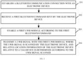
- the method includes the following. Establish a Bluetooth communication connection with an electronic device. Receive a first Bluetooth command sent by the electronic device. Enable the first UWB module according to the first Bluetooth command. Transmit a UWB signal with the first UWB module, where the UWB signal is scanned by the electronic device, and relative location information of the electronic device relative to the tag device is determined according to the UWB signal scanned.
- a searching and positioning apparatus in implementations of the disclosure.
- the apparatus includes a first connecting unit, a sending unit, a scanning unit, and a determining unit.
- the first connecting unit is configured to establish a Bluetooth communication connection with a tag device, where the tag device includes a first UWB module.
- the sending unit is configured to send a first Bluetooth command to the tag device, where the first Bluetooth command instructs the tag device to enable the first UWB module and transmit a UWB signal with the first UWB module.
- the scanning unit is configured to scan the UWB signal transmitted by the first UWB module.
- the determining unit is configured to determine relative location information of an electronic device relative to the tag device according to the UWB signal scanned.
- a searching and positioning apparatus is provided in implementations of the disclosure.
- the apparatus is applicable to a tag device.
- the tag device includes a first UWB module.
- the apparatus includes a second connecting unit, a receiving unit, a control unit, and a transmitting unit.
- the second connecting unit is configured to establish a Bluetooth wireless connection with an electronic device.
- the receiving unit is configured to receive a first Bluetooth command sent by the electronic device.
- the control unit is configured to enable the first UWB module according to the first Bluetooth command.
- the transmitting unit is configured to transmit a UWB signal with the first UWB module, where the UWB signal is scanned by the electronic device, and relative location information of the electronic device relative to the tag device is determined according to the UWB signal scanned.
- an electronic device in implementations of the disclosure.
- the electronic device includes a processor, a memory, a communication interface, and one or more programs stored in the memory and configured to be executed by the processor.
- the programs include instructions for performing operations in the first aspect of implementations of the disclosure.
- a tag device in implementations of the disclosure.
- the tag device includes a first UWB module, a microcontroller unit (MCU) chip, a memory, a communication interface, and one or more programs stored in the memory and configured to be executed by the MCU chip.
- the programs include instructions for performing operations in the second aspect of implementations of the disclosure.
- a searching and positioning system in implementations of the disclosure.
- the system includes an electronic device and a tag device, where the tag device includes a first UWB module, and the electronic device includes a second UWB module.
- the electronic device is configured to establish a Bluetooth communication connection with the tag device and send a first Bluetooth command to the tag device.
- the tag device is configured to enable the first UWB module according to the first Bluetooth command and transmit a UWB signal with the first UWB module.
- the electronic device is further configured to scan the UWB signal transmitted by the first UWB module, and determine relative location information of the electronic device relative to the tag device according to the UWB signal scanned.
- a computer-readable storage medium in implementations of the disclosure.
- the computer-readable storage medium is configured to store computer programs for electronic data interchange (EDI) which are operable with a computer to perform some or all operations described in the first aspect or in the second aspect of implementations of the disclosure.
- EDI electronic data interchange
- a computer program product in implementations of the disclosure.
- the computer program product includes a non-transitory computer-readable storage medium that stores computer programs.
- the computer programs are operable with a computer to perform some or all operations described in the first aspect or in the second aspect of implementations of the disclosure.
- the computer program product may be a software installation package.
- the electronic device establishes the Bluetooth communication connection with the tag device, where the tag device includes the first UWB module.
- the electronic device sends the first Bluetooth command to the tag device, where the first Bluetooth command instructs the tag device to enable the first UWB module and transmit a UWB signal with the first UWB module.
- the electronic device scans the UWB signal transmitted by the first UWB module, and determines the relative location information of the electronic device relative to the tag device according to the UWB signal scanned.
- the tag device can control a turn-on time of the first UWB module according to the first Bluetooth command, and the tag device will not enable the first UWB module if no first Bluetooth command is received.
- the electronic device scans the UWB signal transmitted by the tag device, and the tag device is responsible only for UWB-signal transmission without performing positioning and calculation, thereby reducing power consumption of the tag device.
- the tag device can be found by the user quickly and accurately.
- FIG. 1A is a schematic structural diagram of an electronic device provided in implementations of the disclosure.
- the electronic device 100 includes a store-and-process circuit 110, and a sensor 170 coupled with the store-and-process circuit 110.
- the electronic device 100 may include a control circuit.
- the control circuit may include the store-and-process circuit 110.
- the store-and-process circuit 110 may include a memory, such as a hard drive memory, a non-transitory memory (such as a flash memory, other electronically programmable read-only memories used to form a solid-state drive, etc.), a transitory memory (such as a static random access memory, a dynamic random access memory, etc.), etc., and implementations of the disclosure are not limited in this regard.
- the store-and-process circuit 110 has a processing circuit used to control operations of the electronic device 100.
- the processing circuit can be implemented based on one or more microprocessors, microcontrollers, digital signal processors, baseband processors, power management units, audio codec chips, application-specific integrated circuits, display driver integrated circuits, etc.
- the store-and-process circuit 110 can be configured to run software of the electronic device 100, for example, an internet browsing application, a voice over internet protocol (VOIP) phone call application, an email application, a media playback application, an operating system function, etc.
- the software may be used to perform some control operations, such as camera-based image collection, ambient light sensor-based ambient light measurements, proximity sensor-based proximity state measurements, information display function based on status indicators such as status indicator lamps of light-emitting diodes (LEDs), touch sensor-based touch event detection, functions associated with displaying information on multiple (e.g., layered) display screens, operations associated with implementing wireless communication functions, operations associated with collecting and generating audio signals, control operations associated with collecting and processing button-press event data, and other functions of the electronic device 100, and implementations of the disclosure are not limited in this regard.
- the electronic device 100 may include an input-output circuit 150.
- the input-output circuit 150 can be configured to realize data input and data output of the electronic device 100, that is, to allow the electronic device 100 to receive data from an external device and also allow the electronic device 100 to output data to an external device.
- the input-output circuit 150 can further include the sensor 170.
- the sensor 170 may include an ultrasonic fingerprint recognition module, and may also include an ambient light sensor, an optical or capacitive proximity sensor, a touch sensor (e.g., based on an optical touch sensor and/or a capacitive touch sensor, where the touch sensor may be a part of a touch display screen or may be used independently as a touch sensor structure), an acceleration sensor, and other sensors.
- the ultrasonic fingerprint recognition module may be integrated under a screen, or may be disposed on a side surface or a back surface of the electronic device, which is not limited herein.
- the ultrasonic fingerprint recognition module can be configured to capture fingerprint images.
- the sensor 170 may include a first camera and a second camera.
- the first camera may be a front camera or a rear camera
- the second camera may be a front camera or a rear camera.
- the second camera may be an infrared radiation (IR) camera or a visible-light camera.
- IR infrared radiation
- a pupil reflects an infrared light, and therefore, the IR camera is more accurate than an RGB camera in pupil image shooting.
- the visible-light camera requires further pupil detections, and has higher computational precision and accuracy as well as higher versatility than the IR camera, but is computationally expensive.
- the input-output circuit 150 can further include one or more display screens, such as a display screen 130.
- the display screen 130 may include one or more of a liquid crystal display, an organic LED (OLED) display, an electronic ink display, a plasma display, and displays based on other display technologies.
- the display screen 130 may include an array of touch sensors (i.e., the display screen 130 may be a touch display screen).
- the touch sensor may be a capacitive touch sensor formed by an array of transparent touch sensor electrodes (e.g., indium tin oxide (ITO) electrodes), or may be a touch sensor formed based on other touch technologies, such as acoustic touch, pressure sensitive touch, resistance touch, optical touch, etc., and implementations of the disclosure are not limited in this regard.
- ITO indium tin oxide
- the electronic device 100 may further include an audio assembly 140.
- the audio assembly 140 is configured to provide the electronic device 100 with audio input and output functions.
- the audio assembly 140 of the electronic device 100 may include speakers, microphones, buzzers, tone generators, and other assemblies for generating and detecting sound.
- a communication circuit 120 is configured to provide the electronic device 100 with the ability to communicate with external devices.
- the communication circuit 120 may include an analog/digital input-output interface circuit and a wireless communication circuit based on radio frequency signals and/or optical signals.
- the wireless communication circuit of the communication circuit 120 may include a radio frequency transceiver circuit, a power amplifier circuit, a low-noise amplifier, a switch, a filter, and an antenna.
- the wireless communication circuit of the communication circuit 120 includes a circuit for supporting near field communication (NFC) by transmitting and receiving near-field coupled electromagnetic signals.
- the communication circuit 120 includes an NFC antenna and an NFC transceiver.
- the communication circuit 120 may further include transceivers and antennas for a cellular telephone, transceiver circuits and antennas for a wireless local area network, etc.
- the communication circuit 120 may further include a second ultra wide band (UWB) module 121.
- the second UWB module 121 can realize ranging or positioning based on UWB technology.
- UWB technology is a radio carrier communication technology, which uses a nanosecond-level non-sinusoidal narrow pulse rather than a sinusoidal carrier to transmit data and thus spans a wide spectrum range.
- UWB technology has advantages of low system complexity, low power spectral density of transmit signals, insensitivity to channel fading, low interception capability, and high positioning precision, etc.
- the second UWB module 121 may include a first antenna and a second antenna. The first antenna may be disposed at one side of the top of the electronic device and the second antenna may be disposed at the other side of the top of the electronic device. A first spacing distance between the first antenna and the second antenna is greater than the half wavelength of a UWB signal, which can ensure positioning precision.
- the communication circuit 120 may further include a second Bluetooth module 122.
- the second Bluetooth module 122 is configured for Bluetooth communication.
- the electronic device 100 may further include a battery, a power management circuit, and other input-output units 160.
- the other input-output units 160 include but are not limited to buttons, joysticks, click wheels, scroll wheels, touch pads, keypads, keyboards, cameras, LEDs, and other status indicators, etc.
- An instruction can be input by a user via the input-output circuit 150 to control operations of the electronic device 100, and state information and other outputs can be received from the electronic device 100 with the input-output circuit 150 outputting data.
- the electronic device in implementations of the disclosure may include various devices that have wireless communication functions, such as handheld devices, in-vehicle devices, computing devices, or other processing devices connected to the wireless modem, as well as various forms of user equipments (UE), mobile stations (MS), terminal devices, etc.
- UE user equipments
- MS mobile stations
- terminal devices etc.
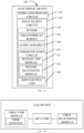
- FIG. 1B is a schematic structural diagram of a tag device provided in implementations of the disclosure.
- the tag device includes a microcontroller unit (MCU) chip and a first UWB module.
- the tag device may further include a first Bluetooth module.
- the first UWB module may include a third antenna.
- the tag device in implementations of the disclosure may include various devices that have wireless communication functions, such as handheld devices, computing devices, wearable devices, or other processing devices connected to the wireless modem, as well as various forms of UEs, MSs, terminal devices, etc.
- the tag device may specifically include devices in the form of the following products: remote controls, keys, smart bracelets, smart watches, wireless earphones, or smart glasses, etc., which is not limited herein.
- the electronic device and the tag device may be devices of the same type, or may be devices of different types.
- the electronic device and the tag device may communicate with each other based on UWB technology, or based on Bluetooth technology.
- the tag device usually has a small size and a relatively small battery capacity, and therefore, power consumption needs to be reduced as much as possible.
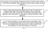
- FIG. 1C is a schematic flowchart of a searching and positioning method provided in implementations of the disclosure. The method is applicable to the electronic device illustrated in FIG. 1A . As illustrated in FIG. 1C , the method provided in the disclosure includes the following.
- the tag 101 establish a Bluetooth communication connection with a tag device.
- the tag device includes a first UWB module.
- the electronic device may include a second Bluetooth module
- the tag device may further include a first Bluetooth module.
- the Bluetooth communication connection can be established with the first Bluetooth module of the tag device via the second Bluetooth module.
- the first Bluetooth module of the tag device may be set to be always on and be in a standby state.
- the second Bluetooth module can be enabled by the electronic device, and the second Bluetooth module establishes the Bluetooth communication connection with the first Bluetooth module of the tag device.
- the tag device in the solution further includes the first UWB module, but the first UWB module is not always on, while the first Bluetooth module is kept to be always on, thereby reducing power consumption of the tag device.
- the 102 send a first Bluetooth command or instruction to the tag device.
- the first Bluetooth command is used for instructing the tag device to enable the first UWB module and transmit a UWB signal with the first UWB module.
- the electronic device can send the first Bluetooth command to the first Bluetooth module via the second Bluetooth module, such that the tag device can enable the first UWB module once the first Bluetooth command is received by the tag device via the first Bluetooth module.
- the tag device may further include an MCU chip.
- the first Bluetooth module can wake up the MCU chip, and the first UWB module is enabled by the MCU chip.
- the tag device can control a turn-on time of the first UWB module according to the first Bluetooth command, and the tag device will not enable the first UWB module if no first Bluetooth command is received, which is possible to reduce power consumption of the tag device, thereby saving a power of the tag device.
- the first UWB module may include at least one third antenna, and a UWB signal(s) is transmitted by the at least one third antenna.
- the tag device can be provided with only one third antenna, and a UWB signal is transmitted by the third antenna at a preset transmission period. As such, it is possible to further reduce power consumption of the tag device.
- the UWB signal transmitted by the first UWB module can be scanned with the second UWB module, and the relative location information can be determined according to the UWB signal scanned.
- the UWB signal transmitted by the first UWB module is scanned by the first UWB module, and the tag device is responsible only for UWB-signal transmission without performing positioning and calculation, thereby reducing power consumption of the tag device.
- the relative location information may include a relative angle of the electronic device relative to the tag device and a relative distance between the electronic device and the tag device.
- the tag device may take the form of any one of the following products: remote controls, keys, smart bracelets, smart watches, wireless earphones, or smart glasses, etc.
- the tag device of any one of the above types can be found by a user quickly and accurately.
- FIG. 1D is a schematic diagram illustrating arrangement of a first antenna and a second antenna in an electronic device provided in implementations of the disclosure.
- the second UWB module may include a first antenna and a second antenna, where the first antenna and the second antenna are in the same plane, and the plane can be parallel to a top frame of the electronic device.
- the first antenna may be disposed at one side of the top of the electronic device, and the second antenna may be disposed at the other side of the top of the electronic device.
- a first spacing distance between the first antenna and the second antenna is greater than the half wavelength of the UWB signal, which can ensure positioning precision.
- the UWB signal can be received by each of the first antenna and the second antenna, and as such, the relative location information can be determined according to a UWB signal received by the first antenna and a UWB signal received by the second antenna.
- the electronic device can determine the relative location information of the electronic device relative to the tag device according to the UWB signal scanned.
- FIG. 1E is a schematic diagram illustrating determination of relative location information of an electronic device relative to a tag device according to a scanned UWB signal provided in implementations of the disclosure. As illustrated in FIG. 1E , a distance between the first antenna and the third antenna can be determined according to the UWB signal received by the first antenna, and a distance between the second antenna and the third antenna can be determined according to the UWB signal received by the second antenna.
- the relative angle of the electronic device relative to the tag device as well as the relative distance between the electronic device and the tag device can be determined according to the distance between the first antenna and the third antenna, the distance between the second antenna and the third antenna, and the first spacing distance between the first antenna and the second antenna.
- a coordinate system can be established based on a plane on which the first antenna, the second antenna, and the third antenna are located. Origin O in the coordinate system is a middle point of a line between the first antenna and the second antenna.
- the distance between the first antenna and the third antenna, the distance between the second antenna and the third antenna, and the first spacing distance between the first antenna and the second antenna are represented by the three sides of triangle ABC, where point A corresponds to coordinates of the first antenna, point B corresponds to coordinates of the second antenna, and point C corresponds to coordinates of the third antenna.
- a distance between the third antenna (point A ) and origin O as well as an included angle between AO and AB can be calculated.
- the distance between the third antenna (point A) and origin O is taken as the relative distance between the electronic device and the tag device
- the included angle between AO and AB is taken as the relative angle of the electronic device relative to the tag device.
- the electronic device includes the second UWB module, and the second UWB module includes the first antenna and the second antenna.
- the UWB signal transmitted by the first UWB module may be scanned as follows.
- the location information of the tag device is determined according to the UWB signal scanned as follows.
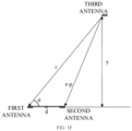
- FIG. 1F is another schematic diagram illustrating determination of relative location information of an electronic device relative to a tag device according to a scanned UWB signal provided in implementations of the disclosure.
- a distance between the electronic device and the tag device is much longer than the first spacing distance between the first antenna and the second antenna.
- a first target distance between the electronic device and the tag device, a first distance between the first antenna and the tag device, and a second distance between the second antenna and the tag device have relatively small differences.
- the first tangential angle of the first antenna relative to the tag device can be determined, and the first distance between the electronic device and the tag device can be determined according to the first tangential angle and the distance for the UWB signal to reach the first antenna.
- the first tangential angle is taken as the relative angle of the electronic device relative to the tag device, and the first distance is taken as the relative distance between the electronic device and the tag device.
- the first distance and the first tangential angle are taken as the relative location information.
- the first tangential angle (i.e., first angle) of the first antenna relative to the tag device and a second tangential angle (i.e., second angle) of the second antenna relative to the tag device can be firstly determined.
- the first distance between the first antenna and the tag device is determined according to the first tangential angle and the distance for by the UWB signal to reach the first antenna
- the second distance between the second antenna and the tag device is determined according to the second tangential angle and a distance for the UWB signal to reach the second antenna.
- the first tangential angle and the second tangential angle are averaged to obtain the relative angle of the electronic device relative to the tag device, and the first distance and the second distance are averaged to obtain the relative distance between the electronic device and the tag device.
- the first tangential angle of the first antenna relative to the tag device is determined according to the UWB signal received by the first antenna and the UWB signal received by the second antenna as follows.
- 3201 determine, according to the UWB signal received by the first antenna and the UWB signal received by the second antenna, a first distance-difference between the distance for the UWB signal to reach the first antenna and the distance for the UWB signal to reach the second antenna.
- 3202 determine the first tangential angle of the first antenna relative to the tag device according to the first distance-difference and the first spacing distance between the first antenna and the second antenna.
- d is the first spacing distance between the first antenna and the second antenna
- r is the first distance between the first antenna and the tag device
- p is the first distance-difference between the distance for the UWB signal to reach the first antenna and the distance for the UWB signal to reach the second antenna.
- the first tangential angle can determined according to distances y and r ( r is the first distance between the first antenna and the tag device).
- a right-angled triangle can be constructed according to distances y and r , where x is one leg of the right-angled triangle, y is the other leg of the right-angled triangle, the hypotenuse of the right-angled triangle is the first distance r between the first antenna and the tag device, and the sine of the first tangential angle a is y / r.
- the method may further include the following after step 103.
- A1 determine an offset angle of the electronic device relative to the tag device according to the relative location information.
- A2 display the offset angle and the first distance onto a display screen.
- the offset angle of the electronic device relative to the tag device can be determined according to the relative location information. For example, as illustrated in FIG. 1E , if the relative angle of the electronic device relative to the tag device is 65°, it can be determined that the offset angle of the electronic device relative to the tag device is 25°, indicating to the user that a direction of shifting the electronic device to the left by 25° is a location of the tag device.
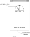
- FIG. 1G is a schematic diagram illustrating display of an offset angle and a first distance onto a display screen provided in implementations of the disclosure.
- the offset angle and the first distance By displaying the offset angle and the first distance onto the display screen, it is possible to instruct the user to shift to the left or to the right according to the offset angle so as to find a direction of the tag device, and instruct the user to move according to the first distance which may be, for example, 1.5 meters (m), such that the tag device can be found by the user quickly.
- the method may further include the following. After the offset angle and the first distance are displayed onto the display screen, the Bluetooth communication connection will be disconnected, and the tag device will be instructed to disable the first UWB module.
- the electronic device can disable a function of: searching for the tag device according to the UWB signal scanned.
- the Bluetooth communication connection can be disconnected.
- the tag device can disable the first UWB module and also disable the MCU chip, thereby reducing power consumption of the tag device and saving a power of the tag device.
- the method may further include the following after the offset angle and the first distance are displayed onto the display screen.
- search for the wireless earphones can be performed by the user according to the offset angle and the first distance. If the electronic device is playing the target audio, the volume of the wireless earphones can be adjusted according to the first distance. Specifically, when the first distance is long, the volume of the wireless earphones will be high, such that the volume of the wireless earphones is high enough to be heard by the user and thus helps the user to search for the wireless earphones.
- the method in implementations of the disclosure is applicable to the electronic device.
- the electronic device establishes the Bluetooth communication connection with the tag device, where the tag device includes the first UWB module.
- the electronic device sends the first Bluetooth command to the tag device, where the first Bluetooth command instructs the tag device to enable the first UWB module and transmit a UWB signal with the first UWB module.
- the electronic device scans the UWB signal transmitted by the first UWB module, and determines the relative location information of the electronic device relative to the tag device according to the UWB signal scanned.
- the tag device can control a turn-on time of the first UWB module according to the first Bluetooth command, and the tag device will not enable the first UWB module if no first Bluetooth command is received.
- the electronic device scans the UWB signal transmitted by the tag device, and the tag device is responsible only for UWB-signal transmission without performing positioning and calculation, thereby reducing power consumption of the tag device.
- the tag device can be found by the user quickly and accurately.
- FIG. 2 is a schematic flowchart of another searching and positioning method provided in implementations of the disclosure.
- the method is applicable to the tag device illustrated in FIG. 1B .
- the tag device includes a first UWB module.
- the method includes the following.
- the tag device may further include a first Bluetooth module, and the electronic device may include a second Bluetooth module.
- the tag device can set the first Bluetooth module to be always on and be in a standby state. After the electronic device initiates a Bluetooth connection request with the tag device, the Bluetooth communication connection with the second Bluetooth module of the electronic device can be established by the first Bluetooth module.
- the first Bluetooth command instructs the tag device to enable the first UWB module.
- the tag device may further include an MCU chip.
- the first Bluetooth module can wake up the MCU chip according to the first Bluetooth command, and the first UWB module is enabled by the MCU chip.
- the tag device will not enable the first UWB module if no first Bluetooth command is received, thereby reducing power consumption of the tag device and saving a power of the tag device.
- the UWB signal is scanned by the electronic device, and relative location information of the electronic device relative to the tag device is determined according to the UWB signal scanned.
- the first UWB module may include at least one third antenna, and a UWB signal is transmitted by the at least one third antenna.
- the tag device can be provided with only one third antenna, and a UWB signal is transmitted by the third antenna at a preset transmission period. As such, it is possible to further reduce power consumption of the tag device.
- the relative location information of the electronic device relative to the tag device is determined by the electronic device according to the UWB signal scanned, which is conducive to finding the tag device quickly and accurately through precise positioning with UWB technology.
- the electronic device scans the UWB signal transmitted by the tag device, and the tag device is responsible only for UWB-signal transmission without performing positioning and calculation, thereby reducing power consumption of the tag device.
- the method may further include the following. After the Bluetooth communication connection is disconnected, the first UWB module and the MCU will be disabled.
- the electronic device can disconnect the Bluetooth communication connection.
- the tag device can disable the first UWB module and the MCU chip, thereby reducing power consumption of the tag device and thus saving a power of the tag device.
- the tag device includes the first UWB module.
- the tag device establishes the Bluetooth communication connection with the electronic device.
- the tag device receives the first Bluetooth command sent by the electronic device.
- the tag device enables the first UWB module according to the first Bluetooth command.
- the tag device transmit a UWB signal with the first UWB module, where the UWB signal is scanned by a second UWB module of the electronic device, and the relative location information of the electronic device relative to the tag device is determined according to the UWB signal scanned.
- the tag device can control a turn-on time of the first UWB module according to the first Bluetooth command, and the tag device will not enable the first UWB module if no first Bluetooth command is received.
- the electronic device scans the UWB signal transmitted by the tag device, and the tag device is responsible only for UWB-signal transmission without performing positioning and calculation, thereby reducing power consumption of the tag device.
- the tag device can be found by the user quickly and accurately.
- FIG. 3 is a schematic architectural diagram of a searching and positioning system provided in implementations of the disclosure.
- the system includes the electronic device illustrated in FIG. 1A and the tag device illustrated in FIG. 1B .
- the tag device includes a first UWB module, and the electronic device includes a second UWB module.
- the second UWB module includes a first antenna and a second antenna, and the first UWB module includes a third antenna.
- the electronic device is configured to establish a Bluetooth communication connection with the tag device and send a first Bluetooth command to the tag device.
- the tag device is configured to enable the first UWB module according to the first Bluetooth command and transmit a UWB signal with the first UWB module.
- the electronic device is further configured to scan the UWB signal transmitted by the first UWB module, and determine relative location information of the electronic device relative to the tag device according to the UWB signal scanned.
- the electronic device establishes the Bluetooth communication connection with the tag device and sends the first Bluetooth command to the tag device.
- the tag device enables the first UWB module according to the first Bluetooth command and transmits a UWB signal with the first UWB module.
- the electronic device scans the UWB signal transmitted by the first UWB module, and determines the relative location information of the electronic device relative to the tag device according to the UWB signal scanned.
- the tag device can control a turn-on time of the first UWB module according to the first Bluetooth command, and the tag device will not enable the first UWB module if no first Bluetooth command is received.
- the electronic device scans the UWB signal transmitted by the tag device, and the tag device is responsible only for UWB-signal transmission without performing positioning and calculation, thereby reducing power consumption of the tag device.
- the tag device can be found by a user quickly and accurately.
- the tag device further includes an MCU chip.
- the tag device is specifically configured to wake up the MCU chip according to the first Bluetooth command, and enable the first UWB module with the MCU chip.
- the electronic device is further configured to disconnect the Bluetooth communication connection after the relative location information of the electronic device relative to the tag device is determined by the electronic device according to the UWB signal scanned.
- the tag device is further configured to disable the first UWB module and the MCU after the Bluetooth communication connection is disconnected.
- the tag device is further configured to send to the electronic device a Bluetooth connection request used for requesting to establish a Bluetooth communication connection with the tag device, and send a second Bluetooth command to the electronic device after the Bluetooth communication connection is established with the tag device.
- the electronic device is further configured to indicate a preset reminding operation according to the second Bluetooth command, where the preset reminding operation is used for reminding existence of the electronic device.
- the tag device is further configured to send a third Bluetooth command to the electronic device.
- the electronic device is further configured to determine a current target application interface of the electronic device, and execute, according to the third Bluetooth command, a preset control operation corresponding to the target application interface.
- the preset reminding operation may include at least one of: ringing, vibration, lighting of an indicator lamp(s), etc., which is not limited herein.
- the preset reminding operation is used for reminding the user of a location of the electronic device, thus helping the user to find the electronic device with aid of the tag device.
- the target application interface may include at least one of: a shooting interface, an audio playback interface, a call interface, etc., which is not limited herein.
- corresponding preset control operations can be set.
- the preset control operation may be a shooting operation.
- the preset control operation may be a song-switching operation.
- the preset control operation may be a call-answering operation, etc., which is not limited herein. In this way, the electronic device can be controlled by the tag device through Bluetooth communication.
- FIG. 4 is a schematic structural diagram of an electronic device provided in implementations of the disclosure.
- the electronic device includes a processor 410, a communication interface 430, a memory 420, and one or more programs 421.
- the one or more programs 421 are stored in the memory 420 and configured to be executed by the processor.
- the programs 421 include instructions for performing the following operations. Establish a Bluetooth communication connection with a tag device, where the tag device includes a first UWB module. Send a first Bluetooth command to the tag device, where the first Bluetooth command instructs the tag device to enable the first UWB module and transmit a UWB signal with the first UWB module. Scan the UWB signal transmitted by the first UWB module, and determine relative location information of the electronic device relative to the tag device according to the UWB signal scanned.
- the electronic device further includes a second UWB module, where the second UWB module includes a first antenna and a second antenna.
- the programs 421 further include instructions to: receive the UWB signal with each of the first antenna and the second antenna.
- the programs 421 further include instructions for performing the following operations. Determine a first tangential angle of the first antenna relative to the tag device according to a UWB signal received by the first antenna and a UWB signal received by the second antenna.
- the programs 421 include instructions for performing the following operations. Determine, according to the UWB signal received by the first antenna and the UWB signal received by the second antenna, a first distance-difference between the distance for the UWB signal to reach the first antenna and a distance for the UWB signal to reach the second antenna. Determine the first tangential angle of the first antenna relative to the tag device according to the first distance-difference and a first spacing distance between the first antenna and the second antenna.
- the programs 421 further include instructions for performing the following operations. Determine an offset angle of the electronic device relative to the tag device according to the relative location information. Display the offset angle and the first distance onto a display screen.
- the programs 421 further include instructions to: disconnect the Bluetooth communication connection and instruct the tag device to disable the first UWB module, after the offset angle and the first distance are displayed onto the display screen.
- FIG. 5 is a schematic structural diagram of a tag device provided in implementations of the disclosure.
- the tag device includes a first UWB module 540, an MCU chip 510, a communication interface 530, a memory 520, and one or more programs 521.
- the one or more programs 521 are stored in the memory 520 and configured to be executed by the processor.
- the programs 521 include instructions for performing the following operations. Establish a Bluetooth communication connection with an electronic device. Receive a first Bluetooth command sent by the electronic device. Enable the first UWB module according to the first Bluetooth command. Transmit a UWB signal with the first UWB module, where the UWB signal is scanned by the electronic device, and relative location information of the electronic device relative to the tag device is determined according to the UWB signal scanned.
- the tag device further includes the MCU chip.
- the programs 421 include instructions to: wake up the MCU chip according to the first Bluetooth command, and enable the first UWB module with the MCU chip.
- the programs 421 further include instructions to: disable the first UWB module and the MCU after the Bluetooth communication connection is disconnected.
- FIG. 6A is a schematic structural diagram of a searching and positioning apparatus provided in implementations of the disclosure.
- the apparatus 600 includes a first connecting unit 601, a sending unit 602, a scanning unit 603, and a determining unit 604.
- the first connecting unit 601 is configured to establish a Bluetooth communication connection with a tag device, where the tag device includes a first UWB module.
- the sending unit 602 is configured to send a first Bluetooth command to the tag device, where the first Bluetooth command instructs the tag device to enable the first UWB module and transmit a UWB signal with the first UWB module.
- the scanning unit 603 is configured to scan the UWB signal transmitted by the first UWB module.
- the determining unit 604 is configured to determine relative location information of an electronic device relative to the tag device according to the UWB signal scanned.
- the electronic device further includes a second UWB module, where the second UWB module includes a first antenna and a second antenna.
- the scanning unit 603 is specifically configured to receive the UWB signal with each of the first antenna and the second antenna.
- the determining unit 604 is specifically configured to: determine a first tangential angle of the first antenna relative to the tag device according to a UWB signal received by the first antenna and a UWB signal received by the second antenna, determine a first distance between the electronic device and the tag device according to the first tangential angle and a distance for the UWB signal to reach the first antenna, and take the first distance and the first tangential angle as the relative location information.
- the determining unit 604 is specifically configured to: determine, according to the UWB signal received by the first antenna and the UWB signal received by the second antenna, a first distance-difference between the distance for the UWB signal to reach the first antenna and a distance for the UWB signal to reach the second antenna; and determine the first tangential angle of the first antenna relative to the tag device according to the first distance-difference and a first spacing distance between the first antenna and the second antenna.
- FIG. 6B illustrates a modified structure of the searching and positioning apparatus illustrated in FIG. 6A .
- the apparatus can further include a display unit 605.
- the determining unit 604 is further configured to determine an offset angle of the electronic device relative to the tag device according to the relative location information.
- the display unit 605 is configured to display the offset angle and the first distance onto a display screen.
- the first connecting unit 601 is further configured to disconnect the Bluetooth communication connection and instruct the tag device to disable the first UWB module, after the offset angle and the first distance are displayed onto the display screen.
- the apparatus in implementations of the disclosure is applicable to the electronic device.
- the electronic device establishes the Bluetooth communication connection with the tag device, where the tag device includes the first UWB module.
- the electronic device sends the first Bluetooth command to the tag device, where the first Bluetooth command instructs the tag device to enable the first UWB module and transmit a UWB signal with the first UWB module.
- the electronic device scans the UWB signal transmitted by the first UWB module, and determines the relative location information of the electronic device relative to the tag device according to the UWB signal scanned.
- the tag device can control a turn-on time of the first UWB module according to the first Bluetooth command, and the tag device will not enable the first UWB module if no first Bluetooth command is received.
- the electronic device scans the UWB signal transmitted by the tag device, and the tag device is responsible only for UWB-signal transmission without performing positioning and calculation, thereby reducing power consumption of the tag device.
- the tag device can be found by a user quickly and accurately.
- FIG. 7 is a schematic structural diagram of another searching and positioning apparatus provided in implementations of the disclosure.
- the apparatus 700 is applicable to the tag device illustrated in FIG. 1B .
- the tag device includes a first UWB module.
- the apparatus 700 includes a second connecting unit 701, a receiving unit 702, a control unit 703, and a transmitting unit 704.
- the second connecting unit is configured to establish a Bluetooth wireless connection with an electronic device.
- the receiving unit is configured to receive a first Bluetooth command sent by the electronic device.
- the control unit is configured to enable the first UWB module according to the first Bluetooth command.
- the transmitting unit is configured to transmit a UWB signal with the first UWB module, where the UWB signal is scanned by the electronic device, and relative location information of the electronic device relative to the tag device is determined according to the UWB signal scanned.
- the tag device further includes an MCU chip.
- the control unit 703 is specifically configured to wake up the MCU chip according to the first Bluetooth command, and enable the first UWB module with the MCU chip.
- the control unit 703 is further configured to disable the first UWB module and the MCU after the Bluetooth communication connection is disconnected.
- the tag device establishes the Bluetooth communication connection with the electronic device.
- the tag device receives the first Bluetooth command sent by the electronic device.
- the tag device enables the first UWB module according to the first Bluetooth command.
- the tag device transmit a UWB signal with the first UWB module, where the UWB signal is scanned by a second UWB module of the electronic device, and the relative location information of the electronic device relative to the tag device is determined according to the UWB signal scanned.
- the tag device can control a turn-on time of the first UWB module according to the first Bluetooth command, and the tag device will not enable the first UWB module if no first Bluetooth command is received.
- the electronic device scans the UWB signal transmitted by the tag device, and the tag device is responsible only for UWB-signal transmission without performing positioning and calculation, thereby reducing power consumption of the tag device.
- the tag device can be found by a user quickly and accurately.
- Implementations of the disclosure further provide a computer storage medium.
- the computer storage medium is configured to store computer programs for electronic data interchange (EDI) which are operable with a computer to perform some or all operations of any one method described in the foregoing method implementations.
- EDI electronic data interchange
- the computer includes an electronic device and a tag device.
- Implementations of the disclosure further provide a computer program product.
- the computer program product includes a non-transitory computer-readable storage medium that stores computer programs.
- the computer programs are operable with a computer to execute some or all operations of any one method described in the foregoing method implementations.
- the computer program product may be a software installation package.
- the computer includes an electronic device and a tag device.
- the apparatuses disclosed in implementations of the disclosure may also be implemented in various other manners.
- the above apparatus implementations are merely illustrative, e.g., the division of units is only a division of logical functions, and other manners of division may be available in practice, e.g., multiple units or assemblies may be combined or may be integrated into another system, or some features may be ignored or skipped.
- the coupling or direct coupling or communication connection as illustrated or discussed may be an indirect coupling or communication connection through some interface, device or unit, and may be electrical, or otherwise.
- Separated units as illustrated may or may not be physically separated.
- Components or parts displayed as units may or may not be physical units, and may reside at one location or may be distributed to multiple networked units. Some or all of the units may be selectively adopted according to practical needs to achieve desired objectives of the technical solutions of implementations.
- various functional units described in implementations of the disclosure may be integrated into one processing unit or may be present as a number of physically separated units, and two or more units may be integrated into one.
- the integrated unit may take the form of hardware or a software functional unit.
- the integrated units are implemented as software functional units and sold or used as standalone products, they may be stored in a computer-readable memory.
- the computer software products can be stored in a memory and may include multiple instructions that, when executed, can cause a computing device, e.g., a personal computer, a server, a network device, etc., to execute some or all operations of the foregoing methods described in various implementations of the disclosure.
- the memory may include various kinds of media that can store program codes, such as a universal serial bus (USB) flash disk, a read only memory (ROM), a random access memory (RAM), a mobile hard drive, a magnetic disk, or an optical disk, etc.
- USB universal serial bus
- ROM read only memory
- RAM random access memory
- mobile hard drive a magnetic disk, or an optical disk, etc.
- the program may be stored in a computer-readable memory, which may include a flash memory, a ROM, a RAM, a magnetic disk, an optical disk, and so on.
Landscapes
- Engineering & Computer Science (AREA)
- Signal Processing (AREA)
- Computer Networks & Wireless Communication (AREA)
- Physics & Mathematics (AREA)
- General Physics & Mathematics (AREA)
- Radar, Positioning & Navigation (AREA)
- Remote Sensing (AREA)
- Telephone Function (AREA)
- Position Fixing By Use Of Radio Waves (AREA)
- Radar Systems Or Details Thereof (AREA)
Applications Claiming Priority (2)
| Application Number | Priority Date | Filing Date | Title |
|---|---|---|---|
| CN202010901555.9A CN111970672A (zh) | 2020-08-31 | 2020-08-31 | 查找定位方法、装置、电子设备及存储介质 |
| PCT/CN2021/106272 WO2022042112A1 (fr) | 2020-08-31 | 2021-07-14 | Procédé et appareil de recherche et de positionnement, dispositif électronique et support de stockage |
Publications (2)
| Publication Number | Publication Date |
|---|---|
| EP4161111A1 true EP4161111A1 (fr) | 2023-04-05 |
| EP4161111A4 EP4161111A4 (fr) | 2023-11-08 |
Family
ID=73401156
Family Applications (1)
| Application Number | Title | Priority Date | Filing Date |
|---|---|---|---|
| EP21859952.0A Withdrawn EP4161111A4 (fr) | 2020-08-31 | 2021-07-14 | Procédé et appareil de recherche et de positionnement, dispositif électronique et support de stockage |
Country Status (3)
| Country | Link |
|---|---|
| EP (1) | EP4161111A4 (fr) |
| CN (1) | CN111970672A (fr) |
| WO (1) | WO2022042112A1 (fr) |
Cited By (1)
| Publication number | Priority date | Publication date | Assignee | Title |
|---|---|---|---|---|
| EP4287728A4 (fr) * | 2021-03-09 | 2024-08-07 | ZTE Corporation | Dispositif de terminal de client, procédé de détection de position et support de stockage lisible par ordinateur |
Families Citing this family (38)
| Publication number | Priority date | Publication date | Assignee | Title |
|---|---|---|---|---|
| CN111970672A (zh) * | 2020-08-31 | 2020-11-20 | Oppo广东移动通信有限公司 | 查找定位方法、装置、电子设备及存储介质 |
| CN112468177B (zh) * | 2020-11-26 | 2022-07-12 | Oppo广东移动通信有限公司 | 射频前端电路、电子设备、以及测距方法 |
| CN112584488B (zh) * | 2020-12-07 | 2023-02-03 | Oppo广东移动通信有限公司 | 定位方法、终端及计算机存储介质 |
| CN112635967B (zh) * | 2020-12-07 | 2023-07-21 | Oppo广东移动通信有限公司 | 电子设备 |
| CN112858996B (zh) * | 2020-12-31 | 2023-08-08 | Oppo广东移动通信有限公司 | 终端、到达角度测量方法及相关装置 |
| CN112911503B (zh) * | 2021-01-20 | 2023-01-13 | 维沃移动通信有限公司 | 数据传输方法及数据传输装置 |
| CN112822325B (zh) * | 2021-01-25 | 2022-03-15 | Oppo广东移动通信有限公司 | 定位显示控制方法及相关装置 |
| CN112925190B (zh) * | 2021-01-25 | 2022-02-01 | 四川写正智能科技有限公司 | 一种多角度安装红外传感器测距的智能手表 |
| CN112911395B (zh) * | 2021-02-26 | 2023-05-23 | 北京小米移动软件有限公司 | 显示控制方法、装置、存储介质及终端 |
| CN113055873B (zh) * | 2021-03-11 | 2022-09-09 | Oppo广东移动通信有限公司 | 设备间的识别方法、装置、电子设备和存储介质 |
| CN113038450B (zh) * | 2021-03-15 | 2023-08-18 | Oppo广东移动通信有限公司 | 终端控制方法、装置、控制模组以及移动终端 |
| CN115086932A (zh) * | 2021-03-16 | 2022-09-20 | Oppo广东移动通信有限公司 | 设备控制方法及相关装置 |
| CN113365254B (zh) * | 2021-04-21 | 2023-11-17 | 珠海新星心科技有限公司 | 基于移动端的uwb设备信息管理系统 |
| CN112996109B (zh) * | 2021-04-21 | 2023-03-14 | 四川巨微集成电路有限公司 | 基于uwb和蓝牙技术融合的定位方法、移动装置及目标装置 |
| CN113179487B (zh) * | 2021-04-22 | 2023-08-29 | Oppo广东移动通信有限公司 | 工作模式控制方法、装置、电子设备和存储介质 |
| CN113141573A (zh) * | 2021-04-27 | 2021-07-20 | 维沃移动通信有限公司 | 提示方法和电子设备 |
| CN115529551A (zh) * | 2021-06-25 | 2022-12-27 | 北京小米移动软件有限公司 | 数据交互方法、装置、系统、移动终端、存储介质 |
| CN113645352B (zh) * | 2021-07-14 | 2024-10-08 | 西安通立软件开发有限公司 | 蓝牙耳机防丢方法、装置、系统及计算机可读存储介质 |
| CN113543310A (zh) * | 2021-07-16 | 2021-10-22 | Oppo广东移动通信有限公司 | 定位方法、装置、电子设备以及计算机可读存储介质 |
| CN115695631A (zh) * | 2021-07-26 | 2023-02-03 | Oppo广东移动通信有限公司 | 信息处理方法、装置、设备及存储介质 |
| CN116061877B (zh) * | 2021-10-29 | 2024-10-29 | 比亚迪股份有限公司 | 车辆被动进入系统、手持终端及车辆控制系统 |
| CN114339591B (zh) * | 2021-12-09 | 2024-03-08 | 青岛海信移动通信技术有限公司 | 基于超宽带芯片进行定位的方法和相关装置 |
| CN115226081B (zh) * | 2021-12-10 | 2023-12-15 | 广州汽车集团股份有限公司 | 汽车钥匙定位方法 |
| CN116347340B (zh) * | 2021-12-24 | 2024-11-15 | 比亚迪股份有限公司 | 汽车钥匙、移动终端以及查找汽车钥匙的方法 |
| CN116668939B (zh) * | 2022-02-21 | 2026-02-17 | Oppo广东移动通信有限公司 | 定位方法、寻物方法、装置、存储介质及电子设备 |
| CN114679681A (zh) * | 2022-03-23 | 2022-06-28 | Oppo广东移动通信有限公司 | 设备控制方法、装置、电子设备及存储介质 |
| CN114827971B (zh) * | 2022-04-26 | 2025-01-21 | 歌尔股份有限公司 | 数据交互方法、系统、uwb设备及介质 |
| CN114885279B (zh) * | 2022-04-28 | 2024-09-13 | Oppo广东移动通信有限公司 | 设备寻找方法、装置、电子设备以及存储介质 |
| CN115065930B (zh) * | 2022-06-16 | 2024-03-19 | 上海乐橘碳蚁科技有限公司 | 一种托盘堆叠检测系统及方法 |
| CN115271010A (zh) * | 2022-07-29 | 2022-11-01 | 北京京东振世信息技术有限公司 | 一种物品信息确定方法、装置、系统、设备及存储介质 |
| CN115442917A (zh) * | 2022-08-17 | 2022-12-06 | 中国银联股份有限公司 | 数据通信方法、装置、设备及可读存储介质 |
| CN117991184A (zh) * | 2022-10-31 | 2024-05-07 | 清研智行(北京)科技有限公司 | 智能钥匙的定位方法、装置、系统、电子设备及介质 |
| CN115715008A (zh) * | 2022-10-31 | 2023-02-24 | 歌尔科技有限公司 | 耳机定位方法、系统、电子设备及计算机可读存储介质 |
| CN117956397A (zh) * | 2022-10-31 | 2024-04-30 | 北京嘀嘀无限科技发展有限公司 | 终端定位的方法和装置 |
| CN116847239A (zh) * | 2023-08-09 | 2023-10-03 | 青岛柯锐思德电子科技有限公司 | 一种具有uwb定位查找功能的tws耳机系统及查找方法 |
| CN119383720A (zh) * | 2023-08-22 | 2025-01-28 | 迈特创新私人有限公司 | 头戴显示设备的位置探测方法、装置、计算机设备及介质 |
| CN117492579B (zh) * | 2023-10-24 | 2024-10-29 | 广东辰奕智能科技股份有限公司 | 基于uwb定位的空鼠控制系统、方法、设备及介质 |
| CN119382687B (zh) * | 2024-10-10 | 2025-06-06 | 广东洲光源红外半导体有限公司 | 一种用于蓝牙耳机的反射式光电开关、方法、电子设备及存储介质 |
Family Cites Families (13)
| Publication number | Priority date | Publication date | Assignee | Title |
|---|---|---|---|---|
| AU2013395182A1 (en) * | 2013-07-24 | 2016-03-10 | Beestar Bv | Locating a tag in an area |
| US20170123039A1 (en) * | 2015-10-29 | 2017-05-04 | Industrial Bank Of Korea | Ultra wideband (uwb)-based high precision positioning method and system |
| EP3374785A4 (fr) * | 2015-11-10 | 2019-07-24 | Xco Tech Inc. | Système et procédé de localisation de position à bande ultralarge |
| KR101750906B1 (ko) * | 2016-01-25 | 2017-07-11 | 동서대학교 산학협력단 | Uwb를 이용한 방위각 산출 시스템 |
| CN206002688U (zh) * | 2016-08-30 | 2017-03-08 | 李言飞 | 一种测距设备以及测距系统 |
| CN108344988B (zh) * | 2016-08-30 | 2022-05-10 | 李言飞 | 一种测距的方法、装置及系统 |
| CN207473082U (zh) * | 2017-11-01 | 2018-06-08 | 北京全迹科技有限公司 | 一种定位装置 |
| KR102656655B1 (ko) * | 2018-08-16 | 2024-04-12 | 삼성전자 주식회사 | 외부 전자 장치의 이동 방향에 기반하여 동작을 수행하는 전자 장치 및 전자 장치의 동작 방법 |
| EP3910460B1 (fr) * | 2018-09-28 | 2023-07-19 | Apple Inc. | Suggestion de destinataires en fonction de la proximité |
| CN110972063B (zh) * | 2019-10-25 | 2020-12-11 | 珠海格力电器股份有限公司 | 一种测距方法、装置、系统及可读介质 |
| CN110839206B (zh) * | 2019-11-26 | 2021-05-11 | 北京布科思科技有限公司 | 基于双模式标签的定位方法及装置 |
| CN111538543B (zh) * | 2020-03-31 | 2024-03-01 | 北京小米移动软件有限公司 | 失物查找方法、装置及存储介质 |
| CN111970672A (zh) * | 2020-08-31 | 2020-11-20 | Oppo广东移动通信有限公司 | 查找定位方法、装置、电子设备及存储介质 |
-
2020
- 2020-08-31 CN CN202010901555.9A patent/CN111970672A/zh active Pending
-
2021
- 2021-07-14 WO PCT/CN2021/106272 patent/WO2022042112A1/fr not_active Ceased
- 2021-07-14 EP EP21859952.0A patent/EP4161111A4/fr not_active Withdrawn
Cited By (1)
| Publication number | Priority date | Publication date | Assignee | Title |
|---|---|---|---|---|
| EP4287728A4 (fr) * | 2021-03-09 | 2024-08-07 | ZTE Corporation | Dispositif de terminal de client, procédé de détection de position et support de stockage lisible par ordinateur |
Also Published As
| Publication number | Publication date |
|---|---|
| WO2022042112A1 (fr) | 2022-03-03 |
| CN111970672A (zh) | 2020-11-20 |
| EP4161111A4 (fr) | 2023-11-08 |
Similar Documents
| Publication | Publication Date | Title |
|---|---|---|
| EP4161111A1 (fr) | Procédé et appareil de recherche et de positionnement, dispositif électronique et support de stockage | |
| US10701158B2 (en) | Control method of wearable apparatus and related apparatuses | |
| EP3691234B1 (fr) | Procédé de photographie et terminal | |
| KR102559651B1 (ko) | 전자기 간섭 제어 방법 및 관련 제품 | |
| CN109639367B (zh) | 电磁干扰的调整方法及相关产品 | |
| US20180314875A1 (en) | Electronic device, fingerprint recognition control method and device | |
| CN108900231B (zh) | 动态天线调整方法及相关产品 | |
| CN109240551B (zh) | 使用手势控制电子装置的方法及相关产品 | |
| WO2018161353A1 (fr) | Procédé et dispositif de partage de photos | |
| CN107103223A (zh) | 解锁控制方法及相关产品 | |
| KR20220166853A (ko) | 디스플레이 방법 및 전자기기 | |
| US11399088B2 (en) | Method for establishing communication connection and related products | |
| US20230319724A1 (en) | Electronic device and operation method therefor | |
| CN109274833A (zh) | 电磁干扰的调整方法及相关产品 | |
| WO2022088999A1 (fr) | Procédé et appareil d'affichage interactif, dispositif électronique, système, et support de stockage | |
| CN108833683B (zh) | 动态天线调整实现方法及相关产品 | |
| CN107948398A (zh) | 一种消息提醒方法及移动终端 | |
| CN108924358A (zh) | 接近传感器控制方法、电子装置及计算机可读存储介质 | |
| CN107770455A (zh) | 一种闪光灯的调整方法和移动终端 | |
| WO2020020060A1 (fr) | Module de projecteur d'appoint, procédé d'identification d'empreintes digitales, et dispositif terminal | |
| CN110431518B (zh) | 一种输出触控信号的方法和电子设备 | |
| CN106092058B (zh) | 信息数据的处理方法、装置及终端 | |
| CN111522613B (zh) | 截屏方法及电子设备 | |
| CN108810261B (zh) | 通话中天线切换方法及相关产品 | |
| CN107528958A (zh) | 移动终端控制方法、装置、可读存储介质和移动终端 |
Legal Events
| Date | Code | Title | Description |
|---|---|---|---|
| STAA | Information on the status of an ep patent application or granted ep patent |
Free format text: STATUS: THE INTERNATIONAL PUBLICATION HAS BEEN MADE |
|
| PUAI | Public reference made under article 153(3) epc to a published international application that has entered the european phase |
Free format text: ORIGINAL CODE: 0009012 |
|
| STAA | Information on the status of an ep patent application or granted ep patent |
Free format text: STATUS: REQUEST FOR EXAMINATION WAS MADE |
|
| 17P | Request for examination filed |
Effective date: 20221228 |
|
| AK | Designated contracting states |
Kind code of ref document: A1 Designated state(s): AL AT BE BG CH CY CZ DE DK EE ES FI FR GB GR HR HU IE IS IT LI LT LU LV MC MK MT NL NO PL PT RO RS SE SI SK SM TR |
|
| A4 | Supplementary search report drawn up and despatched |
Effective date: 20231006 |
|
| RIC1 | Information provided on ipc code assigned before grant |
Ipc: H04W 84/18 20090101ALI20230929BHEP Ipc: H04W 76/14 20180101ALI20230929BHEP Ipc: H04L 5/00 20060101ALI20230929BHEP Ipc: G01S 3/14 20060101ALI20230929BHEP Ipc: G01S 5/12 20060101ALI20230929BHEP Ipc: H04W 4/02 20180101ALI20230929BHEP Ipc: H04W 52/02 20090101ALI20230929BHEP Ipc: H04W 4/80 20180101AFI20230929BHEP |
|
| DAV | Request for validation of the european patent (deleted) | ||
| DAX | Request for extension of the european patent (deleted) | ||
| STAA | Information on the status of an ep patent application or granted ep patent |
Free format text: STATUS: THE APPLICATION HAS BEEN WITHDRAWN |
|
| 18W | Application withdrawn |
Effective date: 20231215 |