EP4161437B1 - Optisches abdrucknehmen des zahnbogens eines patienten - Google Patents
Optisches abdrucknehmen des zahnbogens eines patienten Download PDFInfo
- Publication number
- EP4161437B1 EP4161437B1 EP21730582.0A EP21730582A EP4161437B1 EP 4161437 B1 EP4161437 B1 EP 4161437B1 EP 21730582 A EP21730582 A EP 21730582A EP 4161437 B1 EP4161437 B1 EP 4161437B1
- Authority
- EP
- European Patent Office
- Prior art keywords
- dimensional
- global
- reconstruction
- image
- local
- Prior art date
- Legal status (The legal status is an assumption and is not a legal conclusion. Google has not performed a legal analysis and makes no representation as to the accuracy of the status listed.)
- Active
Links
Images


Classifications
-
- A—HUMAN NECESSITIES
- A61—MEDICAL OR VETERINARY SCIENCE; HYGIENE
- A61C—DENTISTRY; APPARATUS OR METHODS FOR ORAL OR DENTAL HYGIENE
- A61C9/00—Impression cups, i.e. impression trays; Impression methods
- A61C9/004—Means or methods for taking digitized impressions
- A61C9/0046—Data acquisition means or methods
- A61C9/0053—Optical means or methods, e.g. scanning the teeth by a laser or light beam
-
- G—PHYSICS
- G06—COMPUTING OR CALCULATING; COUNTING
- G06T—IMAGE DATA PROCESSING OR GENERATION, IN GENERAL
- G06T5/00—Image enhancement or restoration
- G06T5/50—Image enhancement or restoration using two or more images, e.g. averaging or subtraction
-
- G—PHYSICS
- G06—COMPUTING OR CALCULATING; COUNTING
- G06T—IMAGE DATA PROCESSING OR GENERATION, IN GENERAL
- G06T7/00—Image analysis
- G06T7/30—Determination of transform parameters for the alignment of images, i.e. image registration
- G06T7/33—Determination of transform parameters for the alignment of images, i.e. image registration using feature-based methods
- G06T7/337—Determination of transform parameters for the alignment of images, i.e. image registration using feature-based methods involving reference images or patches
-
- G—PHYSICS
- G06—COMPUTING OR CALCULATING; COUNTING
- G06T—IMAGE DATA PROCESSING OR GENERATION, IN GENERAL
- G06T2207/00—Indexing scheme for image analysis or image enhancement
- G06T2207/20—Special algorithmic details
- G06T2207/20084—Artificial neural networks [ANN]
-
- G—PHYSICS
- G06—COMPUTING OR CALCULATING; COUNTING
- G06T—IMAGE DATA PROCESSING OR GENERATION, IN GENERAL
- G06T2207/00—Indexing scheme for image analysis or image enhancement
- G06T2207/20—Special algorithmic details
- G06T2207/20212—Image combination
- G06T2207/20221—Image fusion; Image merging
-
- G—PHYSICS
- G06—COMPUTING OR CALCULATING; COUNTING
- G06T—IMAGE DATA PROCESSING OR GENERATION, IN GENERAL
- G06T2207/00—Indexing scheme for image analysis or image enhancement
- G06T2207/30—Subject of image; Context of image processing
- G06T2207/30004—Biomedical image processing
- G06T2207/30036—Dental; Teeth
Definitions
- the present invention relates generally to three-dimensional (3D) imaging, and in particular to techniques for taking an optical impression of an oral surface such as a dental arch of a patient, that is to say techniques for generating a three-dimensional reconstruction of a patient's dental arch.
- the embodiments take advantage of progress made in deep learning architectures such as deep neural networks and convolutional neural networks (or convolutional neural networks or even CNN).
- Neural Networks to carry out three-dimensional imaging applications from two-dimensional (2D) images acquired by an acquisition device comprising one or more 2D image sensors.
- the invention finds uses in various applications of oral imaging, for example for dental reconstruction, the creation of dental implants, dental surgery for aesthetic purposes, etc. These examples are not limiting.
- Optical fingerprinting is a more efficient acquisition technique than traditional physicochemical fingerprints, regardless of the material used. Patients prefer the digital impression technique rather than conventional techniques, particularly because of the absence of an induced gag reflex. This technique is less invasive because it requires no preparation, cleaning or disinfection, and the risk of infectious contamination linked to making a traditional impression is eliminated. It is more efficient and ergonomic, the presence of a screen making it possible for the practitioner to do without direct vision in the mouth. It is also faster because data acquisition is relatively short, and it is possible to repeat new captures during the session. Archiving optical impressions is less cumbersome, and this type of impression gives the practitioner the ability to store the captured information indefinitely. Finally, improved transfer of digital images is possible between the dental practitioner's office and the prosthesis manufacturing laboratory, where applicable.
- the optical impression is the first step in a dematerialized digital chain (“ digital workflow” which, in English, means “digital workflow”) ranging from the initial step to clinical placement of the 'a dental prosthesis for example.
- digital workflow which, in English, means “digital workflow”
- CAD/CAM computer-aided design and manufacturing
- CAD/CAM mainly uses the direct method by triangulation in structured light, on the one hand, and the indirect method in active and/or focused structured light, on the other hand .
- the principle of triangulation in structured light consists of placing a light transmitter and a receiver ( ie , a camera), such that the object to be recorded (for example a tooth) is at the top of the triangle formed by the transmitter, receiver and tooth.
- the receiving camera measures the projection of a light point on the tooth.
- a fringe of parallel lights is projected (and not just a light ray).
- the object returns the reflected light rays to the receiver.
- the indirect method using active or structured light consists of projecting a periodic grating onto the object, and observing it through a second grating. It resembles the triangulation method, but differs from it from a mathematical point of view. Indeed, information is perceived thanks to the interference of two wave or macroscopic networks which are projected and observed, respectively, on the object.
- the optical acquisition of oral volumes such as dental arches can be done using an intraoral scanner or IOS (from the English “ intraoral scanner” ). More particularly, the acquisition can be done in two ways: either image by image, or by a continuous digital stream of images. In both cases, a 3D reconstruction mechanism makes it possible to reconstruct the 3D surface of the arch from the 2D images acquired by the IOS.
- recording is done by a succession of closely spaced images.
- the software places the images end to end using common parts that exist between them. THE images that are not usable are rejected in real time.
- the software indicates the missing areas to allow the practitioner to take his impression at the level of this missing.
- the practitioner places the camera above the area to be recorded and it is with the help of an audible or visual signal that the shot is indicated.
- the camera must be very stable. For this, there are stabilization devices which are very useful, especially for inexperienced practitioners.
- This shot is rather suited to sectoral impressions, that is to say those which relate to only a limited portion of the dental arch, because they involve few shots compared to extended impressions, i.e. -say which relate to the entire dental arch or a substantial part of it.
- IOS In addition to IOS, other devices for taking two-dimensional images, which could advantageously be used to combine with IOS.
- the invention starts from the observation that, by combining the wide field of a device of this type, which we will call global device hereafter, with the precision of an IOS, which we will call local device hereafter, the clinical process of acquiring an extended dental impression could be simplified.
- the document US2013330684 discloses a system including an intraoral camera, as well as an array of other sensors/transmitters in the camera body, and/or in a hardware attachment to which the camera can attach.
- a 2D camera is provided to take photos of the patient's face, and possibly make a 3D reconstruction.
- a 3D registration is possible between the 3D model of the patient's dental arch reconstructed by the intraoral camera and the 3D model of the face obtained from photos taken by the 2D camera.
- the document US2008305458A discloses a method which includes generating a three-dimensional intraoral image of the crown of a tooth or crowns of a plurality of selected teeth, generating a three-dimensional image of the root of the tooth or corresponding roots of the teeth corresponding selected images, and the composition of the three-dimensional images of the crown(s) and root(s) of the tooth to produce a composite image.
- the image of the tooth roots is produced by X-ray imaging or magnetic resonance imaging (MRI).
- US2018/168781 describes an augmented reality system for dental practitioners.
- the system includes a scanner, an augmented reality display and a scanner.
- An objective of the system is in particular the display in augmented reality of information on a real-time view taken by the practitioner.
- D1 describes the display of a 2D image on an already established 3D reconstruction.
- the document FR3032282A1 discloses the generation, by augmented reality glasses, of a 3D reconstruction from two or more images.
- This 3D reconstruction can be specified locally by information provided by a more precise intraoral scanner (IOS), with fusion of the 3D reconstruction and this information by 3D registration.
- IOS intraoral scanner
- the invention proposes a method and a device capable of overcoming the drawbacks of the aforementioned prior art which result from the need to ensure "tracking " when taking an extended impression of a patient's dental arch. , that is to say the generation of a three-dimensional reconstruction of the dental arch of a patient.
- the clinical process of taking an extended optical impression of a dental arch of a patient is improved and simplified.
- the practitioner can, thanks to the overall device, take a three-dimensional global reconstruction in a single image, then come with the IOS to reconstruct only the zones (or sectors) of the dental arch requiring finer precision, producing one or more precise local reconstructions.
- An additional algorithm is responsible for merging the global reconstruction with each of the local reconstructions, in order to produce a single mixed three-dimensional reconstruction which corresponds to the desired optical fingerprint.
- the fusion process allows him to do so: in fact, the global reconstruction plays the role of absolute spatial guide for the respective pose of each of the local reconstructions, which are found in the global reconstruction by registration in the same spatial reference frame.
- each image resulting from the IOS can produce a dense 3D reconstruction
- each of these images can lead to a local reconstruction, which can be aligned with the global reconstruction, and which is then added to all the other local reconstructions previously carried out but without the need to an overlap between the corresponding areas of the dental arch to ensure continuity, and without the need to follow an imposed tracing path.
- the continuity of the imprint is ensured by the underlying global reconstruction, whatever the relationship, and even in the absence of relationship, between the local reconstructions of sectors of the dental arch respectively associated with these local reconstructions.
- the overall reconstruction can be generated by the patient himself via a global device such as his smartphone, and transmitted remotely (by email, or by 3G-LTE, 4G or 5G cellular network, etc.) to their practitioner for a first opinion (clinical diagnosis, aesthetics, etc.). If necessary, the practitioner can then offer his patient an appointment in the office in order to complete the overall reconstruction using another local device.
- a global device such as his smartphone
- supervised learning algorithmic models require specific knowledge regarding the problem studied, whereas unsupervised learning algorithmic models do not require it.
- the learning of the convolutional neural network according to the embodiments of the invention is called “semi-supervised” in the sense that the CNN is designed and trained for a particular application.
- the invention can implement multi-view stereoscopy in order to generate more precise global or local 3D reconstructions from, each, a plurality of 2D images of the same object taken at angles of different respective views by a binocular image acquisition device. But it can also overcome this by operating, where appropriate, with a single 2D image sensor, that is to say with a 2D image acquisition device (or 2D imager) which is monocular and which is used to acquire a single 2D image for each 3D reconstruction to be generated.
- a single 2D image sensor that is to say with a 2D image acquisition device (or 2D imager) which is monocular and which is used to acquire a single 2D image for each 3D reconstruction to be generated.
- a second aspect of the invention relates to a computer program comprising instructions which, when the computer program is loaded into the memory of a computer and is executed by a processor of said computer, cause the computer to execute of all the steps of the prediction phase of the method according to the first aspect.
- a fourth and final aspect of the invention relates to an optical impression-taking device comprising a computer which comprises the third digital data processing means of the device according to the third aspect above, as well as means adapted for the implementation of the method according to the first aspect.
- dental arch of a patient we mean all of the 32 teeth forming the dentition of a human being, that is to say all of the static dental tissues including the gum, the teeth, and the possible prosthetic material (crowns, rings, “scan bodies”, “inlay-core”, “inlay-onlay”, etc.). If applicable, depending on the context, we will sometimes distinguish between the upper arch which corresponds to half of the teeth which are implanted on the upper jaw of the individual, on the one hand, and the lower arch which corresponds to the other half of the teeth which are implanted on the lower jaw of said individual, on the other hand.
- optical dental impression of a patient we mean an impression of the patient's dentition in the form of an image, in this case a three-dimensional (3D) image, as opposed to a classic physical impression obtained by molding the teeth. upper and lower dental arches.
- an "extended" optical impression of a dental arch is a representation in the form of a 3D image of the entire arch, or a substantial part of the arch, i.e., a portion of the arch corresponding to at least one hemi-arch, that is to say the half-arch seen from the left side or the right side of the patient.
- Such an extended arch is opposed to an impression of only one sector of said arches, limited to one tooth or only a few teeth.
- An “image”, or “view”, or even “scan” is made up of a set of points of the real three-dimensional scene.
- the points concerned are the points of the real scene projected into the focal plane of the 2D sensor used to acquire the 2D image, and are defined by the pixels of the 2D image.
- the points concerned being a cloud of 3D points obtained by a transformation of a “depth map” (see definition given below).
- Such a point cloud defines a skeleton of the three-dimensional scene.
- a 3D mesh of this cloud of points for example a mesh of triangulated 3D points, can define an envelope.
- n -tuple of images, where n is an integer greater than or equal to unity, is a set of n images taken simultaneously by the sensor(s) of an image acquisition device (or device imaging).
- the imaging device has two sensors, making it possible to generate a doublet (ie, a 2-tuple) of images of the same scene respectively acquired simultaneously by each of these two sensors.
- he can have three, four, five, etc. sensors making it possible to acquire a triplet (ie, a 3-tuple), a quadruplet (ie, a 4-tuple), a quintuplet (ie, a 5-tuple), etc. images of the same scene respectively acquired simultaneously by each of said sensors.
- the device can also include only a single sensor associated with a optical arrangement based on mirror(s) and possibly prism(s), making it possible to successively acquire several images of the same scene seen from different angles.
- a “monocular” imaging device is an acquisition device comprising only a single image sensor.
- Registration (in English “registration ”) consists of determining the spatial relationship between two representations (2D image or 3D surface) of the same object so as to make the representations of the same physical point overlap.
- Pose calculation is the estimation of the position and orientation of the imaged scene relative to the imager (image sensor). This is one of the fundamental problems in computer vision, often called “ Perspective-n-Points” (PnP). This problem consists of estimating the pose (2-tuple [ R j , ; t j ] formed of the rotation matrix R j and the translation vector t j ) of the camera relative to an object in the scene, which amounts to to find the pose allowing to reduce the reprojection error between a point in space and its 2D correspondent in the image.
- a “ Depth map” associated with a 2D image is a form of 2D representation of the reconstructed 3D information, corresponding to the portion of the 3D scene reprojected into the 2D image. In practice, it is a set of values, coded in the form of levels (or shades) of gray, respectively associated with each pixel p i of the 2D image: plus the distance between the point of the three-dimensional scene and the plane of the 2D image is larger, and the darker the pixel.
- FIG. 1 shows the face of a patient, more particularly a young woman 10 smiling.
- detail 15 of the figure which corresponds to the area of the patient's mouth
- the mouth opens when the patient smiles. This reveals at least part of his teeth.
- the area of the mouth includes teeth, in this case the upper dental arch 11, gum 12, the upper lip 13 and the lower lip 14.
- a dental arch of the patient 10 (or both arches, upper and lower) is(are) visible when the patient opens the mouth.
- This dental arch can be the subject of a 3D optical impression taken using the method according to the invention.
- FIG 2 shows a 2D image of the patient's entire dental arch of the figure 1 (upper arch and lower arch included), obtained with a wide-field, low-precision image acquisition device (or “global device” in the context of this description).
- FIG. 3 is an imprecise 3D optical print obtained by three-dimensional reconstruction from the 2D image of the figure 2 , according to modes of implementation of the invention which will be described later.
- FIG 4 is a series of 3D surfaces corresponding to precise local 3D reconstructions of determined sectors of the patient's dental arch of the figure 1 , generated from a plurality of respective associated 2D images, each taken by an image acquisition device, called a local device, having a relatively narrower field but which is relatively more precise than the global device used to the acquisition of the 2D image of the figure 2 .
- reconstruction 41 corresponds to the patient's upper right canine sector
- reconstruction 42 corresponds to the upper left canine sector of the patient
- reconstruction 42 corresponds to the sector of the patient's two lower incisors.
- the figure 5 shows an extended 3D optical impression of the patient's arch, also called precise 3D reconstruction 50, which was obtained by implementing the method according to the invention. More particularly, the improvement in the precision of the precise 3D reconstruction 50 compared to the global 3D reconstruction 30 comes from the registration and fusion of the precise local 3D reconstructions 41, 42 and 43 of the figure 4 with the imprecise overall 3D reconstruction 30 of the Figure 3 . In the precise 3D reconstruction of the figure 5 , the local 3D reconstructions 41, 42 and 43 have been substituted for the corresponding parts of the global 3D reconstruction 30 of the Figure 3 .
- the local 3D reconstructions 41 and 42 are placed on the upper arch, in place at the level of the upper right canine and at the level of the upper left canine, respectively, while the local 3D reconstruction 43 is placed on the lower arch, in place at the level of the two lower incisors.
- the specified 3D reconstruction 50 of the Figure 5 can be displayed on a screen, in virtual reality glasses or in augmented reality glasses; it can also be stored in mass memory or on any other medium appropriate storage; it can also be 3D printed, etc., depending on the application needs.
- the impression taking system comprises a first image capture device 61 (or image acquisition device, or imager) called overall device in the present description.
- this overall device 61 has a relatively wide field of vision but relatively low precision.
- This may be a camera or camera, which may be integrated into a personal wearable device of the patient or practitioner.
- This type of portable device includes, without the list being exhaustive: a mobile phone, a digital tablet, augmented reality glasses, a two-dimensional intraoral camera, a photographic camera, etc. We will subsequently refer to this type of device by the expression “global device” because it allows us to obtain a global view of the arch.
- the overall apparatus 61 is used in video mode, acquiring temporal sequences of 2D images.
- a SLAM ( Simultaneous Localization And Mapping ) type algorithm can be applied sequentially to the sequence (or series) of images, so as to produce an incremental 3D reconstruction progressively. and as new images arrive.
- the global apparatus 61 is used in photo mode, acquiring only one image at a time.
- To produce a dense 3D reconstruction from this single acquired image it is possible to use depth map prediction per single image via the deep learning network 361.
- human of the trade may refer, for example, to the article by Laina et al "Deeper Depth Prediction with Fully Convolutional Residual Networks", IEEE International Conference on 3D Vision (3DV), 2016 .
- the system for implementing the method further comprises a second image capture device 62, called local device in the present description.
- This local device 62 also has, by construction, a relatively narrower field of vision but relatively greater precision, than the field of vision and the precision, respectively, of the global device 61.
- It may be an intraoral camera intended for the 3D reconstruction of intraoral surfaces from passive 2D images, for example an intraoral scanner (IOS).
- IOS intraoral scanner
- Such an intraoral camera 62 is adapted for and intended for the 3D reconstruction of intraoral surfaces from passive 2D images, provided by one or more image sensors.
- This type of device produces 3D surface reconstructions of intraoral tissues in real time.
- the reconstruction can be textured in the case where at least one of the sensors is a color image sensor, for example coded in RGB format.
- the reconstruction can be done using classic multi-view stereoscopy algorithms.
- An example of this kind of algorithm is described, for example, in the article by A. Geiger, J. Ziegler and C. Stiller, "StereoScan: Dense 3d reconstruction in real-time" 2011 IEEE Intelligent Vehicles Symposium (IV), Baden-Baden, 2011, pp. 963-968 .
- each of the image capture devices 61 and 62 can advantageously be a monocular imager, that is to say comprising only a single image sensor.
- a monocular imager actually costs less than binocular imagers (or more generally multi-view stereoscopic devices) adapted to generate 3D reconstructions by multi-view stereoscopy.
- binocular imagers or more generally multi-view stereoscopic devices
- three-dimensional reconstructions can be generated, according to implementation modes, from a single two-dimensional image of the scene to be reconstructed.
- the use of binocular or multi-view stereoscopic imagers is however also possible in the context of implementations of the invention.
- the imager of devices 61 and 62 is for example a passive sensor. It can be a monocular sensor in CMOS technology or CCD technology. A static scene can be imaged by such a monocular image capture device, in black and white or in color.
- each of the devices 61 and 62 and in any case at least the local device 62 providing the more precise local reconstructions comprises at least one sensor color image, for example in RGB format.
- each of the devices 61 and 62 can acquire 2D images in photography mode (a single 2D image at a time) or in video mode (several 2D images over time at any frequency).
- the overall apparatus 61 is adapted for, and intended to produce an overall 3D reconstruction 30 of the dental tissues more quickly (due to its enlarged field of view) but possibly less precise than the local device.
- the local device 62 can then be used to specify all or part of the global reconstruction 30, by producing one or more more precise local reconstructions such as reconstructions 41-43, which can be merged into the global reconstruction 30, at the appropriate location.
- modes of implementation of the 3D reconstruction by the global device 61 which are possible in order to produce an overall 3D reconstruction.
- An implementation method will then be detailed for merging the global reconstruction 30 and the local reconstructions 41-43.
- the system includes a calculation unit 260, for example a microprocessor of a computer (“ Central Processing Unit ”) or a group of processors for example within a graphics card (GPU, stood for “ Graphical Processing Unit ”).
- the computing unit is configured to execute digital data processing algorithms encoded in software.
- the calculation unit 260 is configured to execute a first algorithm 261 and a second 3D reconstruction algorithm 262, as well as an algorithm 263 for merging 3D surfaces, to which we will return. further away.
- the system further comprises a 360 digital information storage system, for example a hard drive in SSD technology ( solid-state drive ) or other.
- the storage system 360 is adapted to permanently store the digital information defining convolutional neural networks 361 and 362 (or CNN). These neural networks 361 and 362 are used by algorithms 261 and 262, respectively, to generate 3D reconstructions from, each time, at least one 2D image.
- the neural networks 361 and 362 are trained for this purpose, during respective learning phases which we will also return to later.
- the storage system 360 can be physically included directly in the optical impression system, or be deported from it, for example on a computer or a remote calculation server. In the latter case, the system can access the calculation server via an ad-hoc communication network, for example via an intranet or via the Internet, for example via an Ethernet network or a wireless radio communications network such as a 3G network. -LTE, 4G or 5G, without affecting the implementation of the process.
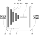
- the deep learning architecture 361 is a convolutional neural network 80 which can have a completely classic structure. This type of CNN is available in bookstores known to those skilled in the art which are freely accessible.
- a two-dimensional image 25 is provided in the form of a pixel matrix. It has two dimensions for a grayscale image. Where applicable, the color is represented by a third dimension, of depth 3 to represent the fundamental colors [Red, Green, Blue].
- FIG 8 shows a particular example of CNN, which is in fact a FCN ( Fully Convolutional Network ) inspired by the article by J. Long, E. Shelhamer and T. Darrell, "Fully convolutional networks for semantic segmentation", IEEE Conference on Computer Vision and Pattern Recognition (CVPR), Boston, MA, 2015, pp. 3431-3440 .
- FCN Fully Convolutional Network
- This FCN has two very distinct parts, according to an encoding/decoding architecture.
- the first part of the encoding FCN is the convolutional part itself. It includes the “convolutional processing layer” 81, which has a succession of filters, or “convolution kernels”, applied in layers.
- the convolutional processing layer 81 functions as a feature extractor from the 2D images admitted as input to the CNN.
- the input image 25 is passed through the succession of convolution kernels, each time creating a new image called a convolution map.
- Each convolution kernel has two convolution layers 811 and 812, and a layer 813 for reducing the resolution of the image by a pooling operation also called local maximum operation (" maxpooling ", in English).
- the output of the convolutional part 81 is then provided as input to a final convolution layer 820 capturing the entire visual field of action of the previous layer, and thus mimicking a fully connected layer (“ fully connected ” layer in English).
- a final deconvolution layer 830 produces as output a depth map which, thanks to the implementation of the embodiments, is a scaled depth map.
- the algorithm 362 which has the function of generating local 3D reconstructions can also have the structure of the convolutional neural network 80 of the figure 8 , or any other known deep learning framework structure.
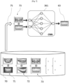
- FIG. 7 is a functional diagram illustrating the learning of one of the convolutional neural networks 361 and 362 which are used by the method of Figure 6 , to generate the global 3D reconstruction and local 3D reconstructions, respectively.
- a 2D image or video acquisition device comparable to the overall device 61 is used, in the sense that it has identical or similar intrinsic characteristics.
- This device is for example a mobile phone comprising one or more passive sensors, at least one of which is a color image sensor (if we wish to obtain textured 3D reconstructions), and whose field of view is wide enough to include in a single image the entire dental arch, even if this means that its 2D precision is lower.
- the relative pose of the 3D model with respect to the 2D image in question is calculated, for example with the aforementioned ePNP algorithm.
- the intrinsic properties of the sensor of the overall device are not known, it is possible to take into account random intrinsic properties, provided that they are kept constant throughout the learning process and then during of the use of the CNN in the prediction phase, for the prediction of global 3D reconstructions)
- the solution proposed for learning the deep learning structures 261 and 262 is a solution for learning the convolutional neural network 80 in a semi-supervised manner.
- the notion of semi-supervision refers to the fact that we have set up a separate process to generate learning data: there is therefore a “manual” transfer of data from one algorithm to another, ie the process of generating stored learning pairs 71, 72, 73, etc. on the one hand, the learning process itself, on the other hand.
- the generation of training data can remain automatic.
- non-supervision refers to the fact that the network would find alone, by analysis of the input data, inference rules allowing it to produce depth maps, which is difficult to imagine.
- total supervision refers to giving learning data not from an automatic process but from a completely manual process, for example by creating depth maps "by hand" by physical measurement, which is not the case here either.
- the semi-supervised learning is carried out from the learning pairs stored in the learning database 70.
- This learning can be implemented by a suitable calculator, for example a graphics processor ( or GPU, from English “Graphical Processing Unit ”) capable of carrying out large amounts of calculation.
- a graphics processor or GPU, from English “Graphical Processing Unit ”
- the learning of the deep learning structure 361 is carried out once and for all, by the manufacturer of the 3D optical impression system. Once trained, this network is capable of predicting a depth map for any image 2D taken by the overall device 61 and comprising a toothed portion. It is then loaded into the 360 data storage system of each device sold, in order to be used in the prediction phase. It can then be subject to updates, if necessary.
- the relevance of the prediction by the deep learning network 361 is not limited only to the people involved in the learning phase. It is limited, on the other hand, to 2D images comprising toothed portions. In addition, the deep learning network 361 can only predict the depth map for the toothed portion (that is to say, rather, all of the dental tissues that are static and visible on the surface, therefore including the gum, teeth, and possible prosthetic material). It is also limited to the type of device involved in learning, because of its intrinsic properties.
- the predicted depth map can be advantageously converted into a textured 3D point cloud, by simple inverse projection.
- This 3D point cloud can in turn be processed by a triangular mesh algorithm (see for example the article by Kazhdan et al "Screened Poisson surface reconstruction", ACM Transactions on Graphics (TOG), Volume 32 (3), June 1, 2013 ) to produce a textured triangulated model.
- the method includes steps allowing the practitioner to obtain the overall 3D reconstruction 30.
- a poorly precise 2D image 20 of the patient's dental arch is captured with the overall device 61.
- the overall 3D reconstruction 30 is generated, from the image 20, by the reconstruction algorithm 261.
- These digital data processing means 261 are adapted to generate an overall three-dimensional reconstruction 30, relatively coarse, of the dental arch from the two-dimensional image 20.
- the algorithm 261 is executed by the calculation unit 260 of the extended 3D impression system.
- the algorithm 261 can be executed by an application program installed on the smartphone, which is therefore capable of generating itself the imprecise overall 3D reconstruction 30. This is then transmitted to the system, by any of the means of communication which have already been presented above, so that the practitioner has them at his disposal.
- the reconstruction algorithm 261 can also be executed in a calculation server, as also already explained in the above, and be transmitted to the system, which is then able to communicate with said server for this purpose.
- the algorithm 261 can be executed in said glasses directly, so that the overall 3D reconstruction 30 is obtained by the practitioner himself, in his cabinet. It is then made accessible to the calculation unit 260, to which the augmented reality glasses can be connected, for example by a USB connection (from the English “ Universal Serial Bus ”), or by Bluetooth TM or by a network short-range wireless network such as Wi-Fi or NFC ( Near Field Communication ), for example.
- a USB connection from the English “ Universal Serial Bus ”
- Bluetooth TM or by a network short-range wireless network such as Wi-Fi or NFC ( Near Field Communication ), for example.
- the method comprises the acquisition of a plurality of local 2D images of respective associated sectors of the dental arch with the local device 62. It is recalled that the local device 62 has a field of relatively more restricted view and relatively higher precision than the overall device 61.
- the method comprises the generation, by second digital data processing means which implement the reconstruction algorithm 362, of respective local 3D reconstructions, relatively more precise than the overall 3D reconstruction 30, of said associated sectors of the dental arch.
- three local 2D images 21, 22 and 23 are acquired, at 161, 162 and 163, respectively, using the local device 62, for example an IOS.
- These acquisitions are carried out by the practitioner, in his office.
- no particular relationship of proximity (and in particular partial recovery), nor order of taking, needs to be respected.
- no tracking path needs to be followed by the practitioner to carry out this series of acquisitions.
- the acquired 2D images can be completely uncorrelated from each other, the only constraint obviously being that they are all images of the same dental arch (ie, images taken of the mouth of the same patient) as the image 2D global 20.
- the practitioner can then place all or part of the local 3D reconstructions 41, 42 and 43 that he has obtained, on top of the spatial canvas constituted by the global 3D reconstruction 30.
- the method implements the fusion, by a fusion algorithm 263 implemented by digital data processing means, of the global three-dimensional reconstruction and local three-dimensional reconstructions into one and the same total three-dimensional reconstruction 50, which is a specified 3D reconstruction ( ie , made more precise).
- the local 3D reconstructions 41, 42 and 43 are respectively substituted for portions of the global three-dimensional reconstruction 30 which correspond to the associated sectors of the patient's dental arch.
- the digital processing means which execute the fusion algorithm 263 are configured to align each local 3D reconstruction 41-43 with the global 3D reconstruction 30, ie, bring the local reconstruction into the reference frame of the global reconstruction. Note that these two reconstructions only differ from each other by a spatial transformation relative to 7 degrees of freedom, namely 3 degrees of freedom in rotation, 3 degrees of freedom in translation, and 1 scale factor.
- each local 3D reconstruction 41-43 has been aligned with the global 3D reconstruction 30, it suffices to replace, in step 190, the portion of global reconstruction 30 covered by each local 3D reconstruction 41, 42 and 43 in order to have a more precise 3D representation in the portions of the global 3D reconstruction 30 for which the local 3D reconstructions have been substituted.
- This reconstruction 50 is an extended optical impression of the patient's dental arch, which presents the best possible precision, determined by that of the local device 62, but which has could be generated more quickly and easily, without the obligation for the practitioner to follow the “ tracking” process.
- the deep learning network 361 can be replaced by a more advanced learning network, which is capable of predicting for each 2D image the depth map as well as a segmentation map, ie, a map 2D giving for each pixel the semantic class to which it belongs.
- the global device can be confused with the local device, ie an intraoral camera, the difference coming from the conditions of use for the generation of the global 3D reconstruction and for that of the local 3D reconstructions, respectively.
- Use as a global device is done for example by moving the camera back from the scene compared to use as a local device, in order to have a global view (entire dental arch) or semi-global. (hemi-arch).
- the image coming from the local sensor such as an IOS at such a distance is often imprecise, but can nevertheless prove usable to obtain a coarse 3D surface, serving as a global 3D reconstruction according to the modes of implementation of the invention.
- the global device 61 and the local device 62 can be one and the same device in the sense that, for example, the intraoral camera 62 can be designed to integrate, on the one hand, one or more local sensors having high precision but a narrow field (typically imaging an area of 3 cm x 2 cm) and, on the other hand, one or more global sensors having relatively lower precision but a relatively higher field (typically imaging a area comprising between a hemi-arch and a complete arch).
- the practitioner performs a first global 3D reconstruction using the global sensors, then switches to the local sensors to locally refine the global 3D reconstruction with local 3D reconstructions.
- the overall device 61 can be a mobile phone equipped with a passive or active 2D sensor, so as to be integrated into a telemedicine approach.
- the image sensor of a mobile phone is a wide field sensor, but which has relatively low precision compared to the standards of imaging in dentistry.
- the 2D image can be taken at home by the patient himself, and this 2D image or a 3D reconstruction which is generated on the basis of said 2D image, can only be obtained at a moment subsequently by the practitioner within his dental practice.
- a patient can in fact take 2D images of their dental arch themselves, alone or with the help of a loved one. These 2D images can be converted into a global 3D reconstruction by algorithm 261, as described previously.
- the patient can then transmit the overall 3D reconstruction to his practitioner for diagnostic, aesthetic advice, etc.
- the practitioner can formulate a first medical and/or aesthetic diagnosis on the basis of this global 3D reconstruction.
- the practitioner does not need a very precise 3D reconstruction for this. He may possibly suggest that the patient make an appointment at the office. During this appointment, the practitioner can then locally refine the 3D reconstruction at least for the sectors of the dental arch (or dental arches) concerned by the planned treatment, using a local device. 62, for example an IOS.
- the overall 3D reconstruction 30 can be transmitted directly to the dentist or dental surgeon, by email, or by a wireless data transmission network, such as a 3G-LTE, 4G or 5G cellular communications network. It can pass through a computer server, or calculation server, in which automatic algorithms can process this overall 3D reconstruction in order to derive various indicators, for example automatic detection of pathologies (cavities, loosening of shoes, etc.), or to aesthetic proposals (automatic alignment of teeth), publish indicative quotes on prosthetic or aesthetic treatments, etc. This indicative information can be offered to the patient, which they can decide to send to their practitioner for their opinion.
- a wireless data transmission network such as a 3G-LTE, 4G or 5G cellular communications network. It can pass through a computer server, or calculation server, in which automatic algorithms can process this overall 3D reconstruction in order to derive various indicators, for example automatic detection of pathologies (cavities, loosening of shoes, etc.), or to aesthetic proposals (automatic alignment of teeth), publish indicative quotes on prosthetic or aesthetic treatments, etc.
- the 3D reconstruction algorithm 261 can be executed on a computer server, based on the 2D image of the arch taken by the patient with his cellphone. In this case, it is the 2D image which is transmitted to the practitioner by email or by 3G-LTE, 4G or 5G network, via said server.
- a server can host a service platform, connecting patients and subscribed practitioners. This platform may have calculation means configured to implement the 3D reconstruction algorithm, in particular. The practitioner then obtains the 3D reconstruction indirectly from the patient, via said service server.
- the overall device may be a pair of augmented reality glasses, for example available in the office of the dentist or dental surgeon.
- the sensor of this type of device has a relatively wide field, ie, capable of covering an extended portion of a dental arch, for example at least one dental hemi-arch.
- This solution has the advantage of allowing the 2D image of the dental arch to be automatically integrated into the practitioner's digital workflow .
- the overall 3D reconstruction can be carried out in real time when the practitioner gazes into the oral cavity through augmented reality glasses.
- the overall 3D reconstruction 30 can be displayed in alpha transparency on the augmented reality glasses as it is estimated. Thanks to the 3D reconstruction method described above, this display is easy to set up, given that the 2D image used to carry out the overall 3D reconstruction 30 is the same as that seen by the glasses. Such placement of the 3D reconstruction in the 2D image, known in itself, allows the practitioner to know at any time which area(s) of the arch he has reconstructed via the glasses, in order to be able to if necessary complete by changing the angle of view.
- the overall reconstruction 30 remains displayed on the augmented reality glasses, as the practitioner completes it using a local image acquisition device. Given that each local 3D reconstruction 41, 42, 43, etc. is aligned with the global 3D reconstruction 30, it is then possible to display it in alpha-transparency on the augmented reality glasses, over the global 3D reconstruction 30, for example by using a different color. This allows the practitioner at any time to know which zone(s) he or she has already specified using the local device.
Landscapes
- Health & Medical Sciences (AREA)
- Engineering & Computer Science (AREA)
- Physics & Mathematics (AREA)
- General Physics & Mathematics (AREA)
- Theoretical Computer Science (AREA)
- Epidemiology (AREA)
- Oral & Maxillofacial Surgery (AREA)
- Dentistry (AREA)
- Optics & Photonics (AREA)
- Life Sciences & Earth Sciences (AREA)
- Animal Behavior & Ethology (AREA)
- General Health & Medical Sciences (AREA)
- Public Health (AREA)
- Veterinary Medicine (AREA)
- Computer Vision & Pattern Recognition (AREA)
- Dental Tools And Instruments Or Auxiliary Dental Instruments (AREA)
- Image Analysis (AREA)
- Image Processing (AREA)
Claims (12)
- Verfahren zur Erzeugung einer dreidimensionalen Rekonstruktion des Zahnbogens eines Patienten, genannt erweiterter optischer Abdruck, mit den folgenden Schritten, die unter der Kontrolle eines Praktikers durchgeführt werden:- Gewinnung mindestens eines globalen zweidimensionalen Bildes des erfassten Zahnbogens mit einem ersten Bildsensor, der ein relativ breites Sichtfeld und eine relativ geringe Genauigkeit aufweist, und Erzeugen einer globalen, relativ groben dreidimensionalen Rekonstruktion des Zahnbogens aus dem zweidimensionalen Bild durch erste digitale Datenverarbeitungsmittel;- Erfassen mehrerer jeweiliger lokaler zweidimensionaler Bilder von jeweiligen zugehörigen Sektoren des Zahnbogens mit einem zweiten Bildsensor, der ein relativ eingeschränkteres Sichtfeld und eine relativ höhere Präzision als der erste Bildsensor aufweist, und Erzeugen von jeweiligen lokalen dreidimensionalen Rekonstruktionen der zugehörigen Sektoren des Zahnbogens durch zweite digitale Datenverarbeitungsmittel, die relativ genauer sind als die globale dreidimensionale Rekonstruktion;- Verschmelzen der globalen dreidimensionalen Rekonstruktion und der lokalen dreidimensionalen Rekonstruktionen zu einer einzigen dreidimensionalen Gesamtrekonstruktion durch einen Verschmelzungsalgorithmus, der von dritten digitalen Datenverarbeitungsmitteln ausgeführt wird, wobei die lokalen dreidimensionalen Rekonstruktionen jeweils durch Teile der globalen dreidimensionalen Rekonstruktion ersetzt werden, die den zugehörigen Sektoren des Zahnbogens entsprechen, wobei die globale Rekonstruktion die Rolle eines absoluten räumlichen Führers spielt, wobei das Zusammenführen eine Einstellung der lokalen dreidimensionalen Rekonstruktionen in der globalen dreidimensionalen Rekonstruktion umfasst, wobei die Einstellung angepasst ist, einen Abstand zwischen den Punktwolken, die jedem der zugehörigen Sektoren des Zahnbogens entsprechen, und der entsprechenden Punktwolke der globalen dreidimensionalen Rekonstruktion zu minimieren.
- Verfahren nach Anspruch 1, worin der erste Bildsensor ein Bildsensor eines tragbaren digitalen Geräts des Patienten, wie z.B. eines Mobiltelefons, ist, und wobei das globale zweidimensionale Bild vom Patienten selbst unter Verwendung seines tragbaren digitalen Geräts erfasst und von dem tragbaren digitalen Gerät an den Behandler übertragen wird, um die globale dreidimensionale Rekonstruktion zu erzeugen.
- Verfahren nach Anspruch 1, welches das Erfassen des globalen zweidimensionalen Bildes durch den Praktiker unter Verwendung des ersten Bildsensors umfasst.
- Verfahren nach Anspruch 3, worin der erste Bildsensor in einer Augmented-Reality-Brille enthalten ist, die ferner die ersten digitalen Datenverarbeitungsmittel zum Erzeugen der globalen dreidimensionalen Rekonstruktion umfasst.
- Verfahren nach einem der vorstehenden Ansprüche, worin der zweite Bildsensor ein intraoraler Scanner ist, der die zweiten digitalen Datenverarbeitungsmittel zum Erzeugen lokaler dreidimensionaler Rekonstruktionen umfasst.
- Verfahren nach einem der Ansprüche 1 bis 5, wobei die globale dreidimensionale Rekonstruktion und/oder die lokalen dreidimensionalen Rekonstruktionen durchgeführt werden, indem jeweils eine Tiefenkarte aus einem einzelnen 2D-Bild erzeugt wird, das von dem ersten Sensor bzw. von dem zweiten Bildsensor erfasst wurde, basierend auf einer Deep-Learning-Architektur, die zuvor für diesen Zweck trainiert wurde.
- Computerprogramm mit Anweisungen, die, wenn das Computerprogramm in den Speicher eines Computers geladen und von einem Prozessor des Computers ausgeführt wird, den Computer veranlassen, alle Schritte des Verfahrens nach einem der Ansprüche 1 bis 6 durchzuführen.
- Vorrichtung zur Erzeugung einer dreidimensionalen Rekonstruktion des Zahnbogens eines Patienten, genannt erweiterter optischer Abdruck, welche umfasst:- einen ersten Bildsensor mit einem relativ weiten Sichtfeld und relativ geringer Genauigkeit zur Aufnahme mindestens eines globalen zweidimensionalen Bildes des Zahnbogens und erste digitale Datenverarbeitungsmittel zum Erzeugen einer globalen, relativ groben dreidimensionalen Rekonstruktion des Zahnbogens aus dem zweidimensionalen Bild;- einen zweiten Bildsensor, der ein relativ eingeschränkteres Sichtfeld und eine relativ höhere Präzision als der erste Bildsensor aufweist, zum Erfassen mehrerer lokaler zweidimensionaler Bildern von jeweiligen zugehörigen Sektoren des Zahnbogens, und zweite digitale Datenverarbeitungsmittel zum Erzeugen jeweiliger lokaler dreidimensionaler Rekonstruktionen der zugehörigen Sektoren des Zahnbogens, die relativ präziser als die globale dreidimensionale Rekonstruktion sind; und- dritte digitale Datenverarbeitungsmittel, die konfiguriert sind, einen Verschmelzungsalgorithmus auszuführen, der geeignet ist, die globale dreidimensionale Rekonstruktion und die lokalen dreidimensionalen Rekonstruktionen zu einer einzigen dreidimensionalen Gesamtrekonstruktion zu verschmelzen, wobei die lokalen dreidimensionalen Rekonstruktionen jeweils durch Teile der globalen dreidimensionalen Rekonstruktion ersetzt werden, die den zugehörigen Sektoren des Zahnbogens entsprechen, wobei die globale Rekonstruktion die Rolle eines absoluten räumlichen Führers spielt, worin der Verschmelzungsalgorithmus eine Einstellung der lokalen dreidimensionalen Rekonstruktionen in der globalen dreidimensionalen Rekonstruktion umfasst, worin die Einstellung angepasst ist, einen Abstand zwischen den Punktwolken, die jedem der zugehörigen Sektoren des Zahnbogens entsprechen, und der entsprechenden Punktwolke der globalen dreidimensionalen Rekonstruktion zu minimieren.
- Vorrichtung nach Anspruch 8, welche eine Augmented-Reality-Brille umfasst, die den ersten Bildsensor und darüber hinaus die ersten digitalen Datenverarbeitungsmittel zur Erzeugung der globalen dreidimensionalen Rekonstruktion umfasst.
- Vorrichtung nach Anspruch 8 oder Anspruch 9, mit einem intraoralen Scanner, der den zweiten Bildsensor und darüber hinaus die zweiten digitalen Datenverarbeitungsmittel zur Erzeugung lokaler dreidimensionaler Rekonstruktionen umfasst.
- Vorrichtung nach einem der Ansprüche 8 bis 10, worin die ersten digitalen Datenverarbeitungsmittel und/oder die zweiten digitalen Datenverarbeitungsmittel konfiguriert sind, die globale dreidimensionale Rekonstruktion bzw. die lokalen dreidimensionalen Rekonstruktionen zu erzeugen, indem sie für jede eine Tiefenkarte aus einem einzelnen 2D-Bild erzeugen, das von dem ersten Sensor bzw. von dem zweiten Bildsensor erfasst wurde, und zwar auf der Grundlage einer Deep-Learning-Architektur, die zuvor für diesen Zweck trainiert wurde.
- Optisches Abdrucknahmegerät mit einem Computer, der die dritten digitalen Datenverarbeitungsmittel der Vorrichtung nach einem der Ansprüche 8 bis 11 sowie zur Durchführung des Verfahrens nach einem der Ansprüche 1 bis 6 geeignete Mittel umfasst.
Applications Claiming Priority (2)
| Application Number | Priority Date | Filing Date | Title |
|---|---|---|---|
| FR2005929A FR3111067A1 (fr) | 2020-06-06 | 2020-06-06 | Prise d'empreinte optique de l’arcade dentaire d’un patient |
| PCT/EP2021/065068 WO2021245274A1 (fr) | 2020-06-06 | 2021-06-04 | Prise d'empreinte optique de l'arcade dentaire d'un patient |
Publications (3)
| Publication Number | Publication Date |
|---|---|
| EP4161437A1 EP4161437A1 (de) | 2023-04-12 |
| EP4161437B1 true EP4161437B1 (de) | 2024-04-17 |
| EP4161437C0 EP4161437C0 (de) | 2024-04-17 |
Family
ID=74095844
Family Applications (1)
| Application Number | Title | Priority Date | Filing Date |
|---|---|---|---|
| EP21730582.0A Active EP4161437B1 (de) | 2020-06-06 | 2021-06-04 | Optisches abdrucknehmen des zahnbogens eines patienten |
Country Status (5)
| Country | Link |
|---|---|
| US (1) | US12433722B2 (de) |
| EP (1) | EP4161437B1 (de) |
| ES (1) | ES2986208T3 (de) |
| FR (1) | FR3111067A1 (de) |
| WO (1) | WO2021245274A1 (de) |
Families Citing this family (7)
| Publication number | Priority date | Publication date | Assignee | Title |
|---|---|---|---|---|
| CN114612541B (zh) * | 2022-03-23 | 2023-04-07 | 江苏万疆高科技有限公司 | 基于3d打印技术的种植牙打印方法、装置、设备及介质 |
| CN114648611B (zh) * | 2022-04-12 | 2023-07-18 | 清华大学 | 局域轨道函数的三维重构方法及装置 |
| CN114869528B (zh) * | 2022-05-02 | 2025-02-21 | 先临三维科技股份有限公司 | 扫描数据处理方法、装置、设备及介质 |
| FR3136153B1 (fr) | 2022-06-07 | 2026-02-20 | Olivier Querbes | Procédé de commande d’un bras robotisé pour imagerie intra-orale |
| CL2023000930A1 (es) * | 2023-03-29 | 2023-10-06 | Fiodormed Spa | Sistema para construir un modelo tridimensional de una dentadura |
| CN117152228B (zh) * | 2023-08-30 | 2026-02-06 | 上海大学 | 基于通道自注意力机制的自监督图像深度估计方法 |
| WO2025171548A1 (en) * | 2024-02-15 | 2025-08-21 | Dental Imaging Technologies Corporation | Point cloud registration for intraoral scanning applications |
Family Cites Families (11)
| Publication number | Priority date | Publication date | Assignee | Title |
|---|---|---|---|---|
| US20080305458A1 (en) | 2007-06-05 | 2008-12-11 | Lemchen Marc S | Method and apparatus for combining a non radiograhpic image with an xray or mri image in three dimensions to obtain accuracy of an intra oral scan and root position |
| US20130330684A1 (en) | 2012-06-06 | 2013-12-12 | Ormco Corporation | Multifunction wand for an intra-oral imaging system |
| FR3021518A1 (fr) * | 2014-05-27 | 2015-12-04 | Francois Duret | Dispositif de visualisation pour faciliter la mesure et le diagnostic 3d par empreinte optique en dentisterie |
| FR3032282B1 (fr) | 2015-02-03 | 2018-09-14 | Francois Duret | Dispositif de visualisation de l'interieur d'une bouche |
| US10888399B2 (en) * | 2016-12-16 | 2021-01-12 | Align Technology, Inc. | Augmented reality enhancements for dental practitioners |
| WO2018149861A1 (en) * | 2017-02-15 | 2018-08-23 | 3Shape A/S | Monitoring the scan volume of a 3d scanner |
| US10916053B1 (en) * | 2019-11-26 | 2021-02-09 | Sdc U.S. Smilepay Spv | Systems and methods for constructing a three-dimensional model from two-dimensional images |
| US10980613B2 (en) * | 2017-12-29 | 2021-04-20 | Align Technology, Inc. | Augmented reality enhancements for dental practitioners |
| EP4792730A2 (de) * | 2018-01-26 | 2026-08-19 | Align Technology, Inc. | Intraorales abtastsystem |
| FR3092426B1 (fr) * | 2019-02-01 | 2021-09-24 | Olivier Querbes | Procédé dynamique d’imagerie tridimensionnelle |
| CN110084840B (zh) * | 2019-04-24 | 2022-05-13 | 阿波罗智能技术(北京)有限公司 | 点云配准方法、装置、服务器和计算机可读介质 |
-
2020
- 2020-06-06 FR FR2005929A patent/FR3111067A1/fr not_active Withdrawn
-
2021
- 2021-06-04 US US18/008,656 patent/US12433722B2/en active Active
- 2021-06-04 WO PCT/EP2021/065068 patent/WO2021245274A1/fr not_active Ceased
- 2021-06-04 EP EP21730582.0A patent/EP4161437B1/de active Active
- 2021-06-04 ES ES21730582T patent/ES2986208T3/es active Active
Also Published As
| Publication number | Publication date |
|---|---|
| WO2021245274A1 (fr) | 2021-12-09 |
| US12433722B2 (en) | 2025-10-07 |
| US20230240818A1 (en) | 2023-08-03 |
| FR3111067A1 (fr) | 2021-12-10 |
| EP4161437A1 (de) | 2023-04-12 |
| EP4161437C0 (de) | 2024-04-17 |
| ES2986208T3 (es) | 2024-11-08 |
Similar Documents
| Publication | Publication Date | Title |
|---|---|---|
| WO2021245274A1 (fr) | Prise d'empreinte optique de l'arcade dentaire d'un patient | |
| EP2579766B1 (de) | Vorrichtung zur aufnahme dreidimensionaler und zeitlicher optischer abdrücke in farbe | |
| EP3148402B1 (de) | Vorrichtung zur betrachtung der innenseite des mundes eines patienten | |
| FR2977469A1 (fr) | Dispositif de mesure tridimensionnelle utilise dans le domaine dentaire | |
| EP3796865B1 (de) | Vorrichtung zur analyse einer zahnsituation | |
| EP3212113B1 (de) | Verfahren zur überwachung einer zahnbehandlung | |
| US9418474B2 (en) | Three-dimensional model refinement | |
| EP3445270A1 (de) | Dentitionskontrollverfahren | |
| FR3027205A1 (fr) | Procede et systeme de modelisation de la cinematique mandibulaire d'un patient | |
| EP3212646A1 (de) | Verfahren zur überwachung der dentition | |
| FR3111222A1 (fr) | Génération de modèles 3D à l’échelle à partir d’images 2D produites par un dispositif d’imagerie monoculaire | |
| FR3111066A1 (fr) | Procédé et dispositif de reconstruction tridimensionnelle d’un visage avec partie dentée à partir d’une seule image | |
| EP3796866A1 (de) | Verfahren zur analyse einer zahnsituation | |
| EP3273905B1 (de) | Verfahren zur bestimmung einer karte der kontakte und/oder abstände zwischen den maxillar- und mandibularbögen eines patienten | |
| WO2020169939A1 (fr) | Procédé d'estimation et de visualisation d'un résultat d'un plan de traitement dentaire | |
| WO2022248513A1 (fr) | Procede d'acquisition d'un modele d'une arcade dentaire | |
| FR2977473A1 (fr) | Dispositif de mesure tridimensionnelle utilise dans le domaine dentaire | |
| EP4533388A1 (de) | Verfahren zur erfassung eines modells eines zahnbogens | |
| EP4348572A1 (de) | Verfahren zur erfassung eines modells eines zahnbogens | |
| FR3135891A1 (fr) | Procede d’acquisition d’un modele d’une arcade dentaire | |
| EP4290466A1 (de) | Verfahren zur modellierung einer anatomischen struktur des menschlichen körpers | |
| WO2015079044A1 (fr) | Systeme et procede de preparation d'un patient a un examen dynamique d'imagerie medicale |
Legal Events
| Date | Code | Title | Description |
|---|---|---|---|
| STAA | Information on the status of an ep patent application or granted ep patent |
Free format text: STATUS: UNKNOWN |
|
| STAA | Information on the status of an ep patent application or granted ep patent |
Free format text: STATUS: THE INTERNATIONAL PUBLICATION HAS BEEN MADE |
|
| PUAI | Public reference made under article 153(3) epc to a published international application that has entered the european phase |
Free format text: ORIGINAL CODE: 0009012 |
|
| STAA | Information on the status of an ep patent application or granted ep patent |
Free format text: STATUS: REQUEST FOR EXAMINATION WAS MADE |
|
| 17P | Request for examination filed |
Effective date: 20230109 |
|
| AK | Designated contracting states |
Kind code of ref document: A1 Designated state(s): AL AT BE BG CH CY CZ DE DK EE ES FI FR GB GR HR HU IE IS IT LI LT LU LV MC MK MT NL NO PL PT RO RS SE SI SK SM TR |
|
| DAV | Request for validation of the european patent (deleted) | ||
| DAX | Request for extension of the european patent (deleted) | ||
| GRAP | Despatch of communication of intention to grant a patent |
Free format text: ORIGINAL CODE: EPIDOSNIGR1 |
|
| STAA | Information on the status of an ep patent application or granted ep patent |
Free format text: STATUS: GRANT OF PATENT IS INTENDED |
|
| INTG | Intention to grant announced |
Effective date: 20231124 |
|
| GRAS | Grant fee paid |
Free format text: ORIGINAL CODE: EPIDOSNIGR3 |
|
| GRAA | (expected) grant |
Free format text: ORIGINAL CODE: 0009210 |
|
| STAA | Information on the status of an ep patent application or granted ep patent |
Free format text: STATUS: THE PATENT HAS BEEN GRANTED |
|
| AK | Designated contracting states |
Kind code of ref document: B1 Designated state(s): AL AT BE BG CH CY CZ DE DK EE ES FI FR GB GR HR HU IE IS IT LI LT LU LV MC MK MT NL NO PL PT RO RS SE SI SK SM TR |
|
| REG | Reference to a national code |
Ref country code: GB Ref legal event code: FG4D Free format text: NOT ENGLISH |
|
| REG | Reference to a national code |
Ref country code: CH Ref legal event code: EP |
|
| REG | Reference to a national code |
Ref country code: DE Ref legal event code: R096 Ref document number: 602021011990 Country of ref document: DE |
|
| REG | Reference to a national code |
Ref country code: IE Ref legal event code: FG4D Free format text: LANGUAGE OF EP DOCUMENT: FRENCH |
|
| U01 | Request for unitary effect filed |
Effective date: 20240516 |
|
| U07 | Unitary effect registered |
Designated state(s): AT BE BG DE DK EE FI FR IT LT LU LV MT NL PT SE SI Effective date: 20240527 |
|
| U20 | Renewal fee for the european patent with unitary effect paid |
Year of fee payment: 4 Effective date: 20240620 |
|
| PG25 | Lapsed in a contracting state [announced via postgrant information from national office to epo] |
Ref country code: IS Free format text: LAPSE BECAUSE OF FAILURE TO SUBMIT A TRANSLATION OF THE DESCRIPTION OR TO PAY THE FEE WITHIN THE PRESCRIBED TIME-LIMIT Effective date: 20240817 |
|
| PG25 | Lapsed in a contracting state [announced via postgrant information from national office to epo] |
Ref country code: HR Free format text: LAPSE BECAUSE OF FAILURE TO SUBMIT A TRANSLATION OF THE DESCRIPTION OR TO PAY THE FEE WITHIN THE PRESCRIBED TIME-LIMIT Effective date: 20240417 |
|
| PG25 | Lapsed in a contracting state [announced via postgrant information from national office to epo] |
Ref country code: GR Free format text: LAPSE BECAUSE OF FAILURE TO SUBMIT A TRANSLATION OF THE DESCRIPTION OR TO PAY THE FEE WITHIN THE PRESCRIBED TIME-LIMIT Effective date: 20240718 |
|
| PG25 | Lapsed in a contracting state [announced via postgrant information from national office to epo] |
Ref country code: PL Free format text: LAPSE BECAUSE OF FAILURE TO SUBMIT A TRANSLATION OF THE DESCRIPTION OR TO PAY THE FEE WITHIN THE PRESCRIBED TIME-LIMIT Effective date: 20240417 |
|
| PG25 | Lapsed in a contracting state [announced via postgrant information from national office to epo] |
Ref country code: PL Free format text: LAPSE BECAUSE OF FAILURE TO SUBMIT A TRANSLATION OF THE DESCRIPTION OR TO PAY THE FEE WITHIN THE PRESCRIBED TIME-LIMIT Effective date: 20240417 Ref country code: NO Free format text: LAPSE BECAUSE OF FAILURE TO SUBMIT A TRANSLATION OF THE DESCRIPTION OR TO PAY THE FEE WITHIN THE PRESCRIBED TIME-LIMIT Effective date: 20240717 Ref country code: IS Free format text: LAPSE BECAUSE OF FAILURE TO SUBMIT A TRANSLATION OF THE DESCRIPTION OR TO PAY THE FEE WITHIN THE PRESCRIBED TIME-LIMIT Effective date: 20240817 Ref country code: HR Free format text: LAPSE BECAUSE OF FAILURE TO SUBMIT A TRANSLATION OF THE DESCRIPTION OR TO PAY THE FEE WITHIN THE PRESCRIBED TIME-LIMIT Effective date: 20240417 Ref country code: GR Free format text: LAPSE BECAUSE OF FAILURE TO SUBMIT A TRANSLATION OF THE DESCRIPTION OR TO PAY THE FEE WITHIN THE PRESCRIBED TIME-LIMIT Effective date: 20240718 Ref country code: RS Free format text: LAPSE BECAUSE OF FAILURE TO SUBMIT A TRANSLATION OF THE DESCRIPTION OR TO PAY THE FEE WITHIN THE PRESCRIBED TIME-LIMIT Effective date: 20240717 |
|
| REG | Reference to a national code |
Ref country code: ES Ref legal event code: FG2A Ref document number: 2986208 Country of ref document: ES Kind code of ref document: T3 Effective date: 20241108 |
|
| REG | Reference to a national code |
Ref country code: DE Ref legal event code: R097 Ref document number: 602021011990 Country of ref document: DE |
|
| PG25 | Lapsed in a contracting state [announced via postgrant information from national office to epo] |
Ref country code: CZ Free format text: LAPSE BECAUSE OF FAILURE TO SUBMIT A TRANSLATION OF THE DESCRIPTION OR TO PAY THE FEE WITHIN THE PRESCRIBED TIME-LIMIT Effective date: 20240417 |
|
| PG25 | Lapsed in a contracting state [announced via postgrant information from national office to epo] |
Ref country code: SK Free format text: LAPSE BECAUSE OF FAILURE TO SUBMIT A TRANSLATION OF THE DESCRIPTION OR TO PAY THE FEE WITHIN THE PRESCRIBED TIME-LIMIT Effective date: 20240417 Ref country code: RO Free format text: LAPSE BECAUSE OF FAILURE TO SUBMIT A TRANSLATION OF THE DESCRIPTION OR TO PAY THE FEE WITHIN THE PRESCRIBED TIME-LIMIT Effective date: 20240417 |
|
| PG25 | Lapsed in a contracting state [announced via postgrant information from national office to epo] |
Ref country code: SM Free format text: LAPSE BECAUSE OF FAILURE TO SUBMIT A TRANSLATION OF THE DESCRIPTION OR TO PAY THE FEE WITHIN THE PRESCRIBED TIME-LIMIT Effective date: 20240417 |
|
| PG25 | Lapsed in a contracting state [announced via postgrant information from national office to epo] |
Ref country code: SM Free format text: LAPSE BECAUSE OF FAILURE TO SUBMIT A TRANSLATION OF THE DESCRIPTION OR TO PAY THE FEE WITHIN THE PRESCRIBED TIME-LIMIT Effective date: 20240417 Ref country code: SK Free format text: LAPSE BECAUSE OF FAILURE TO SUBMIT A TRANSLATION OF THE DESCRIPTION OR TO PAY THE FEE WITHIN THE PRESCRIBED TIME-LIMIT Effective date: 20240417 Ref country code: RO Free format text: LAPSE BECAUSE OF FAILURE TO SUBMIT A TRANSLATION OF THE DESCRIPTION OR TO PAY THE FEE WITHIN THE PRESCRIBED TIME-LIMIT Effective date: 20240417 Ref country code: CZ Free format text: LAPSE BECAUSE OF FAILURE TO SUBMIT A TRANSLATION OF THE DESCRIPTION OR TO PAY THE FEE WITHIN THE PRESCRIBED TIME-LIMIT Effective date: 20240417 |
|
| PLBE | No opposition filed within time limit |
Free format text: ORIGINAL CODE: 0009261 |
|
| STAA | Information on the status of an ep patent application or granted ep patent |
Free format text: STATUS: NO OPPOSITION FILED WITHIN TIME LIMIT |
|
| 26N | No opposition filed |
Effective date: 20250120 |
|
| PGFP | Annual fee paid to national office [announced via postgrant information from national office to epo] |
Ref country code: ES Payment date: 20250926 Year of fee payment: 5 |
|
| PGFP | Annual fee paid to national office [announced via postgrant information from national office to epo] |
Ref country code: CH Payment date: 20250919 Year of fee payment: 5 |
|
| U21 | Renewal fee for the european patent with unitary effect paid with additional fee |
Year of fee payment: 5 Effective date: 20250924 |
|
| PG25 | Lapsed in a contracting state [announced via postgrant information from national office to epo] |
Ref country code: CY Free format text: LAPSE BECAUSE OF FAILURE TO SUBMIT A TRANSLATION OF THE DESCRIPTION OR TO PAY THE FEE WITHIN THE PRESCRIBED TIME-LIMIT; INVALID AB INITIO Effective date: 20210604 |
|
| PG25 | Lapsed in a contracting state [announced via postgrant information from national office to epo] |
Ref country code: HU Free format text: LAPSE BECAUSE OF FAILURE TO SUBMIT A TRANSLATION OF THE DESCRIPTION OR TO PAY THE FEE WITHIN THE PRESCRIBED TIME-LIMIT; INVALID AB INITIO Effective date: 20210604 |
|
| PG25 | Lapsed in a contracting state [announced via postgrant information from national office to epo] |
Ref country code: TR Free format text: LAPSE BECAUSE OF FAILURE TO SUBMIT A TRANSLATION OF THE DESCRIPTION OR TO PAY THE FEE WITHIN THE PRESCRIBED TIME-LIMIT Effective date: 20240417 |
|
| REG | Reference to a national code |
Ref country code: CH Ref legal event code: U11 Free format text: ST27 STATUS EVENT CODE: U-0-0-U10-U11 (AS PROVIDED BY THE NATIONAL OFFICE) Effective date: 20260701 |
|
| PGFP | Annual fee paid to national office [announced via postgrant information from national office to epo] |
Ref country code: GB Payment date: 20260626 Year of fee payment: 6 |
|
| PGFP | Annual fee paid to national office [announced via postgrant information from national office to epo] |
Ref country code: MC Payment date: 20260622 Year of fee payment: 6 |
|
| PGFP | Annual fee paid to national office [announced via postgrant information from national office to epo] |
Ref country code: IE Payment date: 20260625 Year of fee payment: 6 |
|
| U20 | Renewal fee for the european patent with unitary effect paid |
Year of fee payment: 6 Effective date: 20260629 |