EP4162010B1 - Vorrichtung und verfahren zur pyrolyse organischer ausgangsstoffe - Google Patents
Vorrichtung und verfahren zur pyrolyse organischer ausgangsstoffe Download PDFInfo
- Publication number
- EP4162010B1 EP4162010B1 EP21733898.7A EP21733898A EP4162010B1 EP 4162010 B1 EP4162010 B1 EP 4162010B1 EP 21733898 A EP21733898 A EP 21733898A EP 4162010 B1 EP4162010 B1 EP 4162010B1
- Authority
- EP
- European Patent Office
- Prior art keywords
- pyrolysis
- heating
- reactor
- gas
- drum
- Prior art date
- Legal status (The legal status is an assumption and is not a legal conclusion. Google has not performed a legal analysis and makes no representation as to the accuracy of the status listed.)
- Active
Links
Images




Classifications
-
- C—CHEMISTRY; METALLURGY
- C10—PETROLEUM, GAS OR COKE INDUSTRIES; TECHNICAL GASES CONTAINING CARBON MONOXIDE; FUELS; LUBRICANTS; PEAT
- C10B—DESTRUCTIVE DISTILLATION OF CARBONACEOUS MATERIALS FOR PRODUCTION OF GAS, COKE, TAR, OR SIMILAR MATERIALS
- C10B47/00—Destructive distillation of solid carbonaceous materials with indirect heating, e.g. by external combustion
- C10B47/28—Other processes
- C10B47/30—Other processes in rotary ovens or retorts
-
- C—CHEMISTRY; METALLURGY
- C09—DYES; PAINTS; POLISHES; NATURAL RESINS; ADHESIVES; COMPOSITIONS NOT OTHERWISE PROVIDED FOR; APPLICATIONS OF MATERIALS NOT OTHERWISE PROVIDED FOR
- C09C—TREATMENT OF INORGANIC MATERIALS, OTHER THAN FIBROUS FILLERS, TO ENHANCE THEIR PIGMENTING OR FILLING PROPERTIES ; PREPARATION OF CARBON BLACK ; PREPARATION OF INORGANIC MATERIALS WHICH ARE NO SINGLE CHEMICAL COMPOUNDS AND WHICH ARE MAINLY USED AS PIGMENTS OR FILLERS
- C09C1/00—Treatment of specific inorganic materials other than fibrous fillers; Preparation of carbon black
- C09C1/44—Carbon
- C09C1/48—Carbon black
- C09C1/482—Preparation from used rubber products, e.g. tyres
-
- C—CHEMISTRY; METALLURGY
- C10—PETROLEUM, GAS OR COKE INDUSTRIES; TECHNICAL GASES CONTAINING CARBON MONOXIDE; FUELS; LUBRICANTS; PEAT
- C10B—DESTRUCTIVE DISTILLATION OF CARBONACEOUS MATERIALS FOR PRODUCTION OF GAS, COKE, TAR, OR SIMILAR MATERIALS
- C10B47/00—Destructive distillation of solid carbonaceous materials with indirect heating, e.g. by external combustion
- C10B47/28—Other processes
- C10B47/32—Other processes in ovens with mechanical conveying means
- C10B47/44—Other processes in ovens with mechanical conveying means with conveyor-screws
-
- C—CHEMISTRY; METALLURGY
- C10—PETROLEUM, GAS OR COKE INDUSTRIES; TECHNICAL GASES CONTAINING CARBON MONOXIDE; FUELS; LUBRICANTS; PEAT
- C10B—DESTRUCTIVE DISTILLATION OF CARBONACEOUS MATERIALS FOR PRODUCTION OF GAS, COKE, TAR, OR SIMILAR MATERIALS
- C10B53/00—Destructive distillation, specially adapted for particular solid raw materials or solid raw materials in special form
- C10B53/07—Destructive distillation, specially adapted for particular solid raw materials or solid raw materials in special form of solid raw materials consisting of synthetic polymeric materials, e.g. tyres
-
- Y—GENERAL TAGGING OF NEW TECHNOLOGICAL DEVELOPMENTS; GENERAL TAGGING OF CROSS-SECTIONAL TECHNOLOGIES SPANNING OVER SEVERAL SECTIONS OF THE IPC; TECHNICAL SUBJECTS COVERED BY FORMER USPC CROSS-REFERENCE ART COLLECTIONS [XRACs] AND DIGESTS
- Y02—TECHNOLOGIES OR APPLICATIONS FOR MITIGATION OR ADAPTATION AGAINST CLIMATE CHANGE
- Y02P—CLIMATE CHANGE MITIGATION TECHNOLOGIES IN THE PRODUCTION OR PROCESSING OF GOODS
- Y02P20/00—Technologies relating to chemical industry
- Y02P20/141—Feedstock
- Y02P20/143—Feedstock the feedstock being recycled material, e.g. plastics
Definitions
- the present invention relates to a device and a method for the pyrolysis of organic starting materials.
- Pyrolysis generally refers to the thermal splitting of organic compounds. In the process, a bond break is forced within larger molecules of a source material under the exclusion of oxygen and at high temperatures, for example between 300°C and 900°C. Gases, liquids and solids are usually obtained by pyrolysis of the solid source material, with the gases and liquids being separated from a pyrolysis vapor produced during pyrolysis. The proportions and compositions depend on the source material, the pyrolysis temperature, the pressure conditions and the reaction time. During the pyrolysis of polymers, an associated monomer is often produced as part of the pyrolysis vapor.
- the publication EP 0 592 057 B1 A process for the pyrolysis of used tires is known, in which the used tires are decomposed in a pyrolysis bath in a metal bath under reduced pressure and with the exclusion of air and water. The The resulting pyrolysis vapor is separated into a gaseous or a liquid phase after cooling. The process further provides that a portion of the gaseous phase is then returned to the reactor interior above the metal bath and that nitrogen is continuously introduced into the reactor interior above the metal bath.
- the pyrolysis reaction is controlled primarily by controlling the speed of the gas flow in the reaction chamber.
- a process in which pyrolysis is carried out in a continuous process in a rotary tube reactor is known from EN 10 2014 015 281 A1 known from WO 2011/034409 A1
- a reactor for the pyrolysis of biomass is known in which a temperature in a heating chamber is adjusted by a quantity of hot gas flowing through corresponding valves.
- Material from pyrolysis processes which is suitable for further processing into recovered carbon black is characterized in particular by the fact that the toluene-extractable
- the proportion in the material - e.g. the oil content - is less than 1%, preferably less than 0.5%.
- the morphology of the carbon particles is crucial for the intended use as a filler in rubber and plastic applications. Additional carbon formed during pyrolysis does not have the morphological properties of conventional carbon blacks and impairs the quality of the end product.
- the proportion known as oil carbon or "char” should not exceed 2% of the total carbon.
- a system for the pyrolysis of waste material, in particular for the depolymerization of shredded waste tire material, and for producing a starting material that can be further processed into recovered carbon black.
- the system comprises at least one rotary tube reactor, a quenching unit and a burner unit.
- the rotary tube reactor has a reactor drum that rotates about a longitudinal axis during operation and has a drum wall that encloses a reactor interior. Conveying devices are arranged on the inside of the drum wall, which convey waste material to be processed when the reactor drum rotates.
- the reactor interior has at least one heating zone, one reaction zone and one degassing zone.
- the reactor drum has a waste material inlet as well as a (pyrolysis) solids outlet and a (pyrolysis) gas outlet.
- the reactor drum is enclosed by a heating jacket housing and is rotatably mounted so that the reactor drum can rotate about its axis of rotation within the heating jacket housing.
- the heating jacket housing encloses a heating jacket space that is delimited on the inside by the drum wall of the reactor drum.
- the burner unit is designed to burn gas (preferably pyrolysis gas ) to form a heating gas and to generate a heating gas flow through the heating jacket space and is connected to the heating jacket housing via heating gas lines in such a way that the heating gas can be introduced into the heating jacket space so that the reactor drum located in the heating jacket space can be indirectly heated from the outside by means of the heating gas.
- gas preferably pyrolysis gas
- the quenching unit is connected to the gas outlet of the rotary tube reactor and is designed to cool pyrolysis gases generated in the reactor interior during operation.
- heating gas outlet flaps are distributed over the length of the heating jacket housing, which make it possible to influence the flow of the heating gas through the heating jacket space in such a way that different amounts of heat can be supplied to the heating zone, the reaction zone and the degassing zone in the reactor interior.
- the conveying devices are transport spirals formed by guide plates or projections running along a helical path, starting from the drum wall and projecting inwards into the reactor interior.
- the spiral flights of the transport spirals have a different pitch in the reaction zone and in the degassing zone in order to optimize the residence times of the pyrolysis material in the different zones.
- the invention includes the realization that for continuously operating systems - in contrast to batchwise (incremental) pyrolysis processes - there are particular challenges in order to ensure high process stability and consistent product quality over a long operating period. Therefore, a finely tuned (controlled) process mode of the entire system consisting of rotary tube reactor, quench unit and burner system is required. Another problem for permanently stable process control is that in the transition from the reactor interior to the quench unit, the solid particles carried along with the hot fission gases are gradually deposited and can ultimately lead to blockage of the pipeline between the reactor and quench unit.
- the transport spirals inside the reactor drum have different gradients for each zone.
- the drum diameter of individual longitudinal sections of the reactor drum and the distance between the spirals of the transport spirals are also selected for each zone so that the filling height and mixing of the filling are sufficient for the respective process.
- good mixing of the solid filling is required for sufficient material and heat transfer. Mixing is achieved by lifting blades arranged in the spirals.
- a pyrolysis gas outlet pipe is preferably provided, with which the fission gases can be taken directly from the reaction zone and fed to the quenching unit.
- a pyrolysis gas outlet pipe that extends into the reactor drum on the outlet side and through the degassing zone to the end of the reaction zone has proven to be a solution to counteract this disadvantage.
- this solution ensures that the fission products can leave the reactor interior more quickly, thus also avoiding the disadvantages mentioned above (recombination and additional formation of fission carbon) and thus improving the quality of the recovered carbon black.
- the pipe cleaning device is characterized by the fact that a The cleaning element is guided through the pyrolysis gas outlet pipe by means of a rack - starting at the quench inlet to the end of the pipe inside the reactor drum - whereby the deposits are removed and transported to an inlet opening of the pyrolysis gas outlet pipe and thus reach the reaction zone of the reactor drum.
- the rack with the cleaning element is then moved backwards again and thus completely led out of the pyrolysis gas outlet pipe.
- the rack is driven by a drive unit with a gear motor and a gear.
- the rack, the cleaning element and the drive gear are in the rest position in a closed pipe section arranged directly opposite the pyrolysis gas outlet pipe.
- a variant of the arrangement has proven to be effective in which a burner system supplies two pyrolysis reactors with heating gas.
- the heating gas generated in the combustion chamber by burning the pyrolysis gases with air reaches a temperature of 850°C there.
- the heating gas is mixed in a mixing section with recirculating and already used heating gas in order to achieve the required heating gas temperature of 580 to 680°C and to provide a large volume flow of heating gas.
- the regulated heat supply to each reactor takes place through heating gas inlet flaps on the lower inlet to the heating jacket chamber of the rotary tube reactors.
- the heat distribution along the length of the reactor drum is achieved by heating gas outlet flaps arranged at the top of the heating jacket housing, which are distributed along the length of the heating jacket housing and whose respective opening degree ensures the heat requirement of the respective reactor zone.
- the positions (opening degrees) of the heating gas outlet flaps can be set very precisely and are coordinated with one another.
- a preferred flap position configuration that has proven effective for tire chips results in a distribution of the amount of heat supplied of 20% for the heating zone, 70% for the reaction zone and 10% for the degassing zone of the reactor drum.
- the heating gases that enter and are used via the heating gas outlet flaps of the two heating jacket housings flow into the collecting line for recirculation of the heating gas and typically have a temperature of 550 °C.
- the heating gas produced in the mixing section from recirculating heating gas and fresh heating gas from the burner unit, which is not required for heating the reactors, can be fed into further thermal use as a heat transfer medium and then, if necessary, subjected to flue gas cleaning.
- One advantage is the heat distribution that can be achieved with this design and the possibility of compensating for fluctuations and disturbances in the process flow of a reactor without using primary energy in the form of natural gas or liquid gas for the burner unit.
- One such disturbance in the process flow can be, for example, the cyclic operation of the pipe cleaning device described above. Pyrolysis gas (syngas; non-condensed portion of the fission products) provided by the suction fan of the quench unit is completely burned in the burner unit.
- the pyrolysis gas typically has a temperature of 40°C at the quench outlet. If there are fluctuations in the process flow of a reactor and an increased heat requirement for pyrolysis, the quench outlet temperature of the pyrolysis gases can be increased by changing the quench operating parameters. This increases the amount of pyrolysis gas by the components in the cracked gas that would otherwise have condensed out in liquid form in the pyrolysis oil.
- the pressure control for the internal pressure of the reactors to a value in the range of 50 to 150 Pa overpressure (0.5 to 1.5 mbar g) is achieved via the induced draught fan of the quench unit.
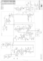
- a system 10 for the pyrolysis of waste material comprises a burner unit 12, one or more rotary tube reactors 14 and one or more quenching units 16; see Figure 1 .
- the rotary tube reactor 14 has a reactor drum 18 which is arranged in a heating jacket housing 20 so as to be rotatable about a rotation axis.
- the reactor drum 18 has a waste material inlet 22 at one longitudinal end and a pyrolysis solids outlet 24 at its other longitudinal end. In addition, the reactor drum 18 is connected to a pyrolysis gas outlet 26.
- the reactor drum 18 encloses a reactor interior 28 and forms a heating zone 30, a reaction zone 32 and a degassing zone 34 in this reactor interior 28.
- the reactor interior 28 is enclosed by a drum wall 36, which in turn is enclosed by the heating jacket housing 20, so that between the heating jacket housing 20 and the drum wall 36 there is a heating jacket space 38 into which heating gas can be introduced.
- the heating gas for heating the reactor drum 18 and its contents is generated by the burner unit 12. Heating gas is fed from the burner unit 12 to a heating gas inlet 42 in the heating jacket housing 20 via a heating gas supply line 40.
- the heating gas inlet 42 is arranged near the waste material inlet 22 below the same.
- Above the reactor drum 18, the heating jacket space 38 has several heating gas outlet flaps 44 distributed along the longitudinal axis of the reactor drum 18, the degree of opening of which is adjustable and adjustable. Heating gas entering the heating jacket space 38 through the heating gas inlet 42 can thus flow around the drum wall 36 to the heating gas outlet flaps 44 and in this way heat the reactor drum 18 and its contents from the outside.
- the temperature distribution in the heating jacket space 38 and thus also the temperature distribution in the reactor interior 28 can be controlled and adjusted. In this way, it is possible in particular to set suitable temperatures for the heating zone 30, the reaction zone 32 and the degassing zone 34 in the reactor drum 18.
- Heating gas exiting the heating jacket chamber 38 through the heating gas outlet flaps 44 is returned via a heating gas recirculation line 46 and can be mixed with heating gas generated by the burner unit 12.
- a burner unit 12 supplies two rotary tube reactors 14 with heating gas.
- the heating gas produced by the burner unit 12 by combustion of the pyrolysis gases with air reaches a temperature of 850°C there.
- the heating gas is mixed with recirculated and already used heating gas in a heating gas mixing section 48 in order to achieve the required heating gas temperature of 580 to 680 °C and to provide a large volume flow of heating gas.
- the regulated heat supply to each rotary tube reactor 14 is carried out by heating gas inlet flaps 50 on the lower heating gas inlet 42 on the input side to the heating jacket space 38 of the rotary tube reactors 14.
- the heat distribution over the length of the reactor drum 18 is realized by heating gas outlet flaps 44 arranged longitudinally distributed over the length of the heating jacket housing at the top, the respective degree of opening of which ensures the heat requirement of the respective reactor zone 30, 32 and 34.
- the positions (degrees of opening) of the heating gas outlet flaps 44 can be set very precisely and are coordinated with one another.
- a preferred flap position configuration that has proven successful for tire chips results in a distribution of the amount of heat supplied of 20% for the heating zone 30, 70% for the reaction zone 32 and 10% for the degassing zone 34 of the reactor drum 18.
- the heating gases that are used and reach the heating gas outlet flaps 44 of the two heating jacket housings 20 flow into the recirculation manifold 46 and typically have a temperature of 550 °C.
- the heating gas generated in the heating gas mixing section 48 from recirculating heating gas and fresh heating gas from the burner unit 12, which is not required for heating the rotary tube reactors 14, can be fed to further thermal use as a heat transfer medium and then subjected to flue gas cleaning if necessary.
- the combustion unit 12 is thus connected to two rotary tube reactors 14, so that heating gas is fed to the two rotary tube reactors 14 via two heating gas supply lines (each of which leads to a rotary tube reactor) and heating gas emerging from the respective heating jacket housing 20 can also be fed back again via a common heating gas recirculation line 46 located at the top and arranged centrally between the two rotary tube reactors.
- two heating gas supply lines each of which leads to a rotary tube reactor
- heating gas emerging from the respective heating jacket housing 20 can also be fed back again via a common heating gas recirculation line 46 located at the top and arranged centrally between the two rotary tube reactors.
- a further improvement of the pyrolysis process - alternatively or in addition to the previously described temperature setting - results from a design of the reactor drum, which results in suitable residence times of the pyrolysis material in the individual zones 30, 32, 34 inside the reactor drum.
- the residence times are structurally set so that the respective processes such as heating in the heating zone 30, cleavage reaction or pyrolysis or depolymerization in the reactor zone 32 and residual degassing in the degassing zone 34 run completely and zone-related at a given speed of the reactor drum 18 and a given throughput of pyrolysis material.
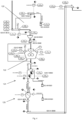
- the transport of the pyrolysis material in the longitudinal direction of the reactor drum 18 from its waste material inlet 22 to the pyrolysis solids outlet 24 is effected by transport spirals 52 which are arranged inside the reactor drum 18, projecting inwards from the drum wall 36; see Figure 2
- the transport spirals 52 inside the reactor drum 18 have different gradients depending on the zone.
- a transport spiral 52.1 in the heating zone 30 therefore has a different gradient than a transport spiral 52.2 in the reaction zone 32 or a transport spiral 52.3 in the degassing zone 34.
- the reactor drum 18 has different drum diameters along its longitudinal axis. The drum diameter is maximum in the reaction zone 32.
- the distance between the spirals of the individual transport spirals 52.1, 52.2 and 52.3 is also not identical in all three zones.
- the respective drum diameter of the transport drum 18 and the distance between the spirals of the transport spirals 52 for each of the three zones are dimensioned such that a desired filling height and a desired mixing of the filling of the pyrolysis material are sufficient for the respective process taking place - i.e. heating, cracking reaction and residual degassing.
- waste material such as tire chips
- a feed screw conveyor 56 which conveys the waste material from the waste material inlet 22 into the reactor drum 18.
- the waste material is conveyed by the transport spiral 52.1 to the heating zone 30 and mixed within the heating zone 30 by the lifting blades 54.
- the pyrolysis material such as the waste tire chips, is then conveyed further in the reaction zone 32 by the transport spiral 52.2 to the degassing zone 34.
- the pyrolysis material is then conveyed by the transport spiral 52.3 with a greater gradient and therefore also at a greater conveying speed to the pyrolysis solids outlet 24.
- the pyrolysis solids produced in the reactor drum 18 fall into a collecting shaft 58, from which it is transported away by a discharge screw conveyor 60.
- Pyrolysis gas produced during pyrolysis can exit the reactor interior 28 through a pyrolysis gas outlet pipe 62.
- the pyrolysis gas outlet pipe 62 advantageously extends from the pyrolysis gas outlet 26 into the reaction zone 32.
- the pyrolysis gas outlet pipe 62 runs centrally in the reactor drum 18 along the axis of rotation of the reactor drum 18, whereby an exact alignment of the pyrolysis gas outlet pipe 62 with the axis of rotation of the reactor drum 18 is not necessary.
- Pyrolysis gas produced during pyrolysis in the reactor interior 28 can enter an inlet opening 64 of the pyrolysis gas outlet pipe and flow through the pyrolysis gas outlet pipe 62 through the pyrolysis gas outlet 26 to the quench unit 16.
- the inlet opening 64 of the pyrolysis gas outlet pipe 62 is located, as already mentioned, in the area of the reaction zone 32. This largely prevents solids, which are typically dust-like and are stirred up in the degassing zone 34, from being entrained and discharged from the reactor interior 28 through the pyrolysis gas outlet 26 by the pyrolysis gases generated in the reaction zone 32.
- a further advantage of the pyrolysis gas outlet pipe 62, which extends into the reaction zone 32, is that the fission products generated during pyrolysis - i.e. the pyrolysis gas - can leave the reactor interior 28 more quickly and such disadvantages as the recombination of the fission products and the additional formation of fission carbon can be avoided. In this way, the quality of the recovered carbon black is further improved.
- the pyrolysis gases exiting from the pyrolysis gas outlet pipe 62 are cooled so that those pyrolysis gases with a higher evaporation temperature are liquefied to form pyrolysis oil.
- the liquid produced in the quench unit 16 - the pyrolysis oil - is collected in a collecting container 66 in the lower end of the quench unit 16 and removed by means of a pump 68.
- Part of the pyrolysis oil is led through a pyrolysis oil recirculation line 70 through a liquid cooler 72 and returned to the quench unit 16 and sprayed there by means of a spray unit 74.
- Pyrolysis oil produced in the quench unit is - if it is not recirculated - discharged via a liquid outlet 76.
- Non-liquefied pyrolysis gas remaining in the quench unit 16 is finally fed to the burner unit 12 via a pyrolysis gas line 78 and burned there to form heating gas.
- Pyrolysis gas provided by the quench unit 16 is a syngas formed from the non-condensed portions of the pyrolysis fission products.
- the pyrolysis gas typically has a temperature of 40 °C at the outlet of the quench unit 16. If there are fluctuations in the process flow of one or both rotary tube reactors 14 and an increased heat requirement for the pyrolysis, the quench outlet temperature of the pyrolysis gases can be increased by changing the operating parameter values of the quench unit 16. This also increases the amount of pyrolysis gas by those components in the fission gas that would otherwise be liquefied in the quench unit 16 and would then have been present in liquid form in the pyrolysis oil.
- the burner unit 12 is connected to a burner control unit 100 in order to be able to control the air supply to the burner unit 12 in a regulated manner via a fan 102.
- a gas supply control unit 104 controls the amount of pyrolysis gas supplied to the burner unit 12 via a gas supply valve 106.
- the amount of recirculated heating gas supplied to the heating gas mixing section 48 is controlled by means of a recirculation control unit 108, which controls a recirculation heating gas blower 110.
- a quench temperature control unit 112 which controls a pyrolysis oil circulation valve 114. In this way, the amount of cooled pyrolysis oil that is sprayed into the quench unit 16 can be controlled. As previously described, the circulated pyrolysis oil is cooled by means of a water cooler, so that the quench outlet temperature can be controlled via the amount of pyrolysis oil returned.
- a further process control unit 116 is provided for each of the rotary tube reactors 14, which controls the respective induced draft fan 94.
- the rotary tube reactors 14 are operated with an internal pressure in the reactor interior 28 that is approximately 50 Pa to 150 Pa above the ambient pressure. This overpressure is realized via an induced draft fan 94 of the quench unit 16. This makes it possible to react to fluctuations in the amount of pyrolysis gas produced by adjusting the delivery rate in the induced draft fan 94.
- the pyrolysis gases are fed to the burner unit 12 with a supply overpressure of 2000 Pa to 6000 Pa above the ambient pressure.
- a pipe cleaning device 80 which can be used at regular intervals, for example twice a week.
- the pipe cleaning device 80 has a cleaning element 82 whose outer diameter corresponds to the inner diameter of the pyrolysis gas outlet pipe 62.
- the cleaning element 82 can be moved into the pyrolysis gas outlet pipe 62 up to the inlet opening 64 of the pyrolysis gas outlet pipe 62 by means of a rack 84.
- deposits in the pyrolysis gas outlet pipe 62 are removed and transported to the inlet opening 64 of the pyrolysis gas outlet pipe 62, so that they return to the reaction zone 32 in the reactor drum 18.
- the cleaning element 82 can then be moved back again using the rack 84 and completely removed from the pyrolysis gas outlet pipe 62.
- a drive unit 86 with a gear motor 88 and a drive gear 90 is provided in order to drive the rack 84.
- the rack 84, the cleaning element 82 and the drive gear 90 are in their rest position in a closed pipe section 92 arranged directly opposite the pyrolysis gas outlet pipe 62 on the outlet side.
- the pyrolysis process is briefly interrupted by not feeding any waste material into the reactor drum 18 in order to interrupt the formation of pyrolysis gas.
- the pyrolysis solids leaving the reactor drum 18 are first subjected to a solids pre-cleaning process; see Figure 4
- a device 120 is provided for magnetically removing coarse particles from the pyrolysis solid.
- the pyrolysis solid freed of coarse magnetic particles is then fed to a device 122 for coarsely crushing the pyrolysis solid.
- the device 122 crushes the pyrolysis solid into pieces smaller than 2 mm.
- the coarsely crushed pyrolysis solid is then fed to a second device 124 for removing magnetic particles.
- the device 124 removes the finest magnetic particles.
- the magnetic particles removed by the device 120 and the device 124 can each be fed to a steel press.
- the pyrolysis solids freed from fine magnetic components are finally fed to a device 106 for removing coarse components and textile components.
- the pyrolysis solids pre-cleaned in this way are then subjected to fine grinding, for example a jet grinding system 110 as in Figure 5
- the jet milling system 130 has a jet milling device with a classifying wheel 132, which is used to crush and classify the pyrolysis solids and to maintain an upper limit grain size of, for example, 15 ⁇ m.
- a roller mill can also be used in conjunction with a classifying wheel for particle classification.
- the ground pyrolysis solid is finally fed to a stirred tank 134, which serves to remove air from the ground pyrolysis solid in order to achieve a uniform and increased bulk density for subsequent pearling.
- a pearling device 140 is provided, as shown in Figure 6
- the aerating device 140 has a pin mixer and dosing equipment for supplying powder and a water-surfactant mixture.
- the pearled pyrolysis solid is fed to a dryer 150; see Figure 7 .
- This has a drum dryer or a fluid bed dryer for evaporating the pearling water.
- the heat required for drying 150 is preferably provided at least in part by the system 10 in the form of a quantity of heating gas taken from the excess heating gas of the recirculation line 46 and supplied to a heat transfer medium via a heating gas outlet line 126; see also reference number 126 in Fig.1 .
- the pearled and screened pyrolysis solid can be packaged in a packaging device 160.
Landscapes
- Chemical & Material Sciences (AREA)
- Engineering & Computer Science (AREA)
- Oil, Petroleum & Natural Gas (AREA)
- Organic Chemistry (AREA)
- Materials Engineering (AREA)
- Combustion & Propulsion (AREA)
- Processing Of Solid Wastes (AREA)
- Production Of Liquid Hydrocarbon Mixture For Refining Petroleum (AREA)
- Gasification And Melting Of Waste (AREA)
- Separation, Recovery Or Treatment Of Waste Materials Containing Plastics (AREA)
Priority Applications (1)
| Application Number | Priority Date | Filing Date | Title |
|---|---|---|---|
| HRP20240987TT HRP20240987T1 (hr) | 2020-06-09 | 2021-06-09 | Uređaj i postupak za pirolizu organskih polaznih materijala |
Applications Claiming Priority (2)
| Application Number | Priority Date | Filing Date | Title |
|---|---|---|---|
| DE102020115348.1A DE102020115348A1 (de) | 2020-06-09 | 2020-06-09 | Vorrichtung und Verfahren zur Pyrolyse organischer Ausgangsstoffe |
| PCT/EP2021/065485 WO2021250103A1 (de) | 2020-06-09 | 2021-06-09 | Vorrichtung und verfahren zur pyrolyse organischer ausgangsstoffe |
Publications (3)
| Publication Number | Publication Date |
|---|---|
| EP4162010A1 EP4162010A1 (de) | 2023-04-12 |
| EP4162010C0 EP4162010C0 (de) | 2024-06-26 |
| EP4162010B1 true EP4162010B1 (de) | 2024-06-26 |
Family
ID=76553726
Family Applications (1)
| Application Number | Title | Priority Date | Filing Date |
|---|---|---|---|
| EP21733898.7A Active EP4162010B1 (de) | 2020-06-09 | 2021-06-09 | Vorrichtung und verfahren zur pyrolyse organischer ausgangsstoffe |
Country Status (15)
| Country | Link |
|---|---|
| US (1) | US20230227730A1 (pl) |
| EP (1) | EP4162010B1 (pl) |
| JP (1) | JP7851864B2 (pl) |
| CN (1) | CN116209734A (pl) |
| AU (1) | AU2021286879A1 (pl) |
| BR (1) | BR112022024952A2 (pl) |
| CA (1) | CA3186726A1 (pl) |
| DE (1) | DE102020115348A1 (pl) |
| ES (1) | ES2991611T3 (pl) |
| HR (1) | HRP20240987T1 (pl) |
| HU (1) | HUE068422T2 (pl) |
| MX (1) | MX2022015723A (pl) |
| PL (1) | PL4162010T3 (pl) |
| WO (1) | WO2021250103A1 (pl) |
| ZA (1) | ZA202212771B (pl) |
Families Citing this family (2)
| Publication number | Priority date | Publication date | Assignee | Title |
|---|---|---|---|---|
| JP2025507593A (ja) * | 2022-02-17 | 2025-03-21 | ティール セールス インコーポレイテッド | 炭化水素化合物の熱化学生産および精製のためのシステムおよび方法 |
| WO2025131568A1 (en) | 2023-12-18 | 2025-06-26 | Orion Engineered Carbons Gmbh | Sustainable carbon blacks for coloring mineral binders |
Family Cites Families (17)
| Publication number | Priority date | Publication date | Assignee | Title |
|---|---|---|---|---|
| DE69224538D1 (de) * | 1992-07-22 | 1998-04-02 | Covenant Environmental Technol | Methode zur pyrolyse von organischen materialen |
| DE4234385A1 (de) | 1992-10-06 | 1994-04-07 | Formex Trading Gmbh | Verfahren zur Pyrolyse von organischen Stoffen |
| DE4334544A1 (de) | 1993-10-11 | 1995-04-13 | Gartzen Johannes Prof Dr Rer N | Verfahren zur Verwertung eines Ausgangsmaterials |
| US5728361A (en) * | 1995-11-01 | 1998-03-17 | Ferro-Tech Tire Reclamation, Inc. | Method for recovering carbon black from composites |
| US6221329B1 (en) | 1999-03-09 | 2001-04-24 | Svedala Industries, Inc. | Pyrolysis process for reclaiming desirable materials from vehicle tires |
| FI20021223L (fi) * | 2002-06-24 | 2003-12-25 | Andritz Oy | Menetelmä ja poltin rumpu-uuneja varten |
| JP2006349224A (ja) * | 2005-06-14 | 2006-12-28 | Shirakawa Namacon Kyogyo Kumiai | 廃タイヤリサイクル装置 |
| DE102008021019B4 (de) | 2008-04-25 | 2012-06-28 | Eisenmann Ag | Ofen zur Pyrolyse von Abfallmaterial und Verfahren zum Betreiben eines Ofens |
| LV14040B (lv) * | 2009-09-18 | 2009-12-20 | Intec Group, Sia | Biomasas pirolīzes reaktors |
| JP5385819B2 (ja) * | 2010-02-23 | 2014-01-08 | 日本碍子株式会社 | 廃イオン交換樹脂の焼却処理方法 |
| JP2013159778A (ja) * | 2012-02-07 | 2013-08-19 | Yoichi Kiyono | 炭化装置及び炭化材料 |
| JP2013167370A (ja) * | 2012-02-14 | 2013-08-29 | Ishii Hyoki Corp | 焼却灰処理装置 |
| JP2015512972A (ja) * | 2012-02-15 | 2015-04-30 | バドックス エナジー エルエルシーVadxx Energy Llc | 2段階分割帯域熱分解装置 |
| DE102014015281A1 (de) | 2013-10-19 | 2015-04-23 | Crr Carbon Resources Recovery Gmbh | Verfahren und Anordnung zur Verbesserung der Effektivität von Pyrolyseprozessen |
| CN104946279B (zh) * | 2015-06-01 | 2017-09-29 | 农业部规划设计研究院 | 回转式分段加热生物质连续热解设备 |
| CN105176549B (zh) * | 2015-06-23 | 2018-01-12 | 东莞市百大新能源股份有限公司 | 一种生物质热解炭化设备及其控制方法 |
| CN210287232U (zh) * | 2019-04-30 | 2020-04-10 | 四川亚西橡塑机器有限公司 | 一种便于清理的橡塑裂解设备 |
-
2020
- 2020-06-09 DE DE102020115348.1A patent/DE102020115348A1/de active Pending
-
2021
- 2021-06-09 US US18/001,175 patent/US20230227730A1/en active Pending
- 2021-06-09 WO PCT/EP2021/065485 patent/WO2021250103A1/de not_active Ceased
- 2021-06-09 HR HRP20240987TT patent/HRP20240987T1/hr unknown
- 2021-06-09 BR BR112022024952A patent/BR112022024952A2/pt unknown
- 2021-06-09 CA CA3186726A patent/CA3186726A1/en active Pending
- 2021-06-09 EP EP21733898.7A patent/EP4162010B1/de active Active
- 2021-06-09 PL PL21733898.7T patent/PL4162010T3/pl unknown
- 2021-06-09 AU AU2021286879A patent/AU2021286879A1/en active Pending
- 2021-06-09 MX MX2022015723A patent/MX2022015723A/es unknown
- 2021-06-09 JP JP2022576085A patent/JP7851864B2/ja active Active
- 2021-06-09 ES ES21733898T patent/ES2991611T3/es active Active
- 2021-06-09 HU HUE21733898A patent/HUE068422T2/hu unknown
- 2021-06-09 CN CN202180059264.2A patent/CN116209734A/zh active Pending
-
2022
- 2022-11-23 ZA ZA2022/12771A patent/ZA202212771B/en unknown
Also Published As
| Publication number | Publication date |
|---|---|
| HRP20240987T1 (hr) | 2024-11-08 |
| JP7851864B2 (ja) | 2026-04-27 |
| PL4162010T3 (pl) | 2024-11-18 |
| EP4162010A1 (de) | 2023-04-12 |
| WO2021250103A1 (de) | 2021-12-16 |
| EP4162010C0 (de) | 2024-06-26 |
| CN116209734A (zh) | 2023-06-02 |
| US20230227730A1 (en) | 2023-07-20 |
| AU2021286879A1 (en) | 2023-01-19 |
| CA3186726A1 (en) | 2021-12-16 |
| BR112022024952A2 (pt) | 2022-12-27 |
| ZA202212771B (en) | 2023-06-28 |
| HUE068422T2 (hu) | 2024-12-28 |
| DE102020115348A1 (de) | 2021-12-09 |
| ES2991611T3 (es) | 2024-12-04 |
| MX2022015723A (es) | 2023-03-27 |
| JP2023529217A (ja) | 2023-07-07 |
Similar Documents
| Publication | Publication Date | Title |
|---|---|---|
| DE3880155T2 (de) | Pyrolyses von organischem material. | |
| EP4162010B1 (de) | Vorrichtung und verfahren zur pyrolyse organischer ausgangsstoffe | |
| WO2011057822A1 (de) | Vorrichtung und verfahren zur erzeugung eines feinkörnigen brennstoffs aus festen oder pastösen energierohstoffen durch torrefizierung und zerkleinerung | |
| EP2029267B1 (de) | Verfahren und vorrichtung zur kontinuierlichen polymerisation von polymer in fester phase | |
| DE10260739B3 (de) | Verfahren und Anlage zur Herstellung von Metalloxid aus Metallverbindungen | |
| DE10260733A1 (de) | Verfahren und Anlage zur Wärmebehandlung von eisenoxidhaltigen Feststoffen | |
| EP3081622A1 (de) | Verfahren und anlage zur verbesserten herstellung von pyrolyseteer | |
| DE102022125294A1 (de) | Pyrolysereaktor und Verfahren zur thermochemischen Behandlung kohlenstoffhaltiger Abfälle | |
| WO1992005001A1 (de) | Verfahren und anlage zum reduktionsglühen von eisenpulver | |
| DE212016000279U1 (de) | Anlage der thermochemischen Umwandlung von organhaltigen Rohstoffen | |
| EP3178906B1 (de) | Verfahren zur rückgewinnung von russ aus elastomeren | |
| DE3686720T2 (de) | Schlacken-austragesystem fuer einen vergasungsreaktor fuer feste brennstoffe. | |
| EP2393903A2 (de) | Vorrichtung in form eines thermolysereaktors und verfahren zum betreiben eines solchen in einer anordnung zur thermischen zersetzung von abprodukten und abfällen | |
| EP4453132B1 (de) | Pyrolyseverfahren und pyrolysevorrichtung zur herstellung von pyrolysegas und pyrolysekoks | |
| EP2184334A1 (de) | Verfahren und Vorrichtung zum Recycling von kohlenwasserstoff-haltigen Materialien | |
| DE2826918A1 (de) | Verfahren zur verwertung von gummi- und kunststoffabfaellen, insbesondere von altreifen | |
| EP2560750A1 (de) | Vorrichtung und verfahren zur thermischen vorbehandlung von festen einsatzstoffen in einer konzentrisch gestuften wirbelschicht | |
| EP4056632B1 (de) | Verfahren und anlage zur depolymerisation von kunststoffmaterial | |
| WO2011003374A2 (de) | Anordnung und verfahren zur aufbereitung und thermischen behandlung von abprodukten und abfällen und verfahren zum betreiben dieser anordnung (thermolyse-spaltverfahren) | |
| DE202009010833U1 (de) | Anordnung zur Aufbereitung und thermischen Behandlung von Abprodukten und Abfällen | |
| DE102012218864B4 (de) | Verfahren zur Konversion organischer Sekundärrohstoffe zu Ölnebel als Basis für insbesondere Kraftstoffe und Vorrichtung zur Durchführung des Verfahrens | |
| DE3018777A1 (de) | Verfahren zum zerkleinern von produkten bei tiefer temperatur und anlage zur durchfuehrung des verfahrens | |
| EP0108234A2 (de) | Verfahren und Vorrichtung zum Vergasen von Rückständen aus der hydrierenden Verflüssigung von Kohle und/oder von Rückständen aus der Schwerölhydrierung in einem Wirbelbett- oder Flugstromvergaser | |
| DE971805C (de) | Verfahren und Vorrichtung zur Umwandlung von Kohlenwasserstoffoelen | |
| DE102023103391A1 (de) | Anlage und Verfahren zum Aufbereiten vonKunststoff-Recyclingmaterial |
Legal Events
| Date | Code | Title | Description |
|---|---|---|---|
| REG | Reference to a national code |
Ref country code: HR Ref legal event code: TUEP Ref document number: P20240987T Country of ref document: HR |
|
| STAA | Information on the status of an ep patent application or granted ep patent |
Free format text: STATUS: UNKNOWN |
|
| STAA | Information on the status of an ep patent application or granted ep patent |
Free format text: STATUS: THE INTERNATIONAL PUBLICATION HAS BEEN MADE |
|
| PUAI | Public reference made under article 153(3) epc to a published international application that has entered the european phase |
Free format text: ORIGINAL CODE: 0009012 |
|
| STAA | Information on the status of an ep patent application or granted ep patent |
Free format text: STATUS: REQUEST FOR EXAMINATION WAS MADE |
|
| 17P | Request for examination filed |
Effective date: 20230109 |
|
| AK | Designated contracting states |
Kind code of ref document: A1 Designated state(s): AL AT BE BG CH CY CZ DE DK EE ES FI FR GB GR HR HU IE IS IT LI LT LU LV MC MK MT NL NO PL PT RO RS SE SI SK SM TR |
|
| GRAP | Despatch of communication of intention to grant a patent |
Free format text: ORIGINAL CODE: EPIDOSNIGR1 |
|
| STAA | Information on the status of an ep patent application or granted ep patent |
Free format text: STATUS: GRANT OF PATENT IS INTENDED |
|
| INTG | Intention to grant announced |
Effective date: 20240205 |
|
| GRAS | Grant fee paid |
Free format text: ORIGINAL CODE: EPIDOSNIGR3 |
|
| GRAA | (expected) grant |
Free format text: ORIGINAL CODE: 0009210 |
|
| STAA | Information on the status of an ep patent application or granted ep patent |
Free format text: STATUS: THE PATENT HAS BEEN GRANTED |
|
| AK | Designated contracting states |
Kind code of ref document: B1 Designated state(s): AL AT BE BG CH CY CZ DE DK EE ES FI FR GB GR HR HU IE IS IT LI LT LU LV MC MK MT NL NO PL PT RO RS SE SI SK SM TR |
|
| REG | Reference to a national code |
Ref country code: GB Ref legal event code: FG4D Free format text: NOT ENGLISH |
|
| REG | Reference to a national code |
Ref country code: CH Ref legal event code: EP |
|
| REG | Reference to a national code |
Ref country code: DE Ref legal event code: R096 Ref document number: 502021004135 Country of ref document: DE |
|
| U01 | Request for unitary effect filed |
Effective date: 20240726 |
|
| U07 | Unitary effect registered |
Designated state(s): AT BE BG DE DK EE FI FR IT LT LU LV MT NL PT SE SI Effective date: 20240808 |
|
| REG | Reference to a national code |
Ref country code: SK Ref legal event code: T3 Ref document number: E 44659 Country of ref document: SK |
|
| PG25 | Lapsed in a contracting state [announced via postgrant information from national office to epo] |
Ref country code: RS Free format text: LAPSE BECAUSE OF FAILURE TO SUBMIT A TRANSLATION OF THE DESCRIPTION OR TO PAY THE FEE WITHIN THE PRESCRIBED TIME-LIMIT Effective date: 20240926 |
|
| REG | Reference to a national code |
Ref country code: HR Ref legal event code: T1PR Ref document number: P20240987 Country of ref document: HR |
|
| REG | Reference to a national code |
Ref country code: GR Ref legal event code: EP Ref document number: 20240402119 Country of ref document: GR Effective date: 20241111 |
|
| REG | Reference to a national code |
Ref country code: ES Ref legal event code: FG2A Ref document number: 2991611 Country of ref document: ES Kind code of ref document: T3 Effective date: 20241204 |
|
| REG | Reference to a national code |
Ref country code: HU Ref legal event code: AG4A Ref document number: E068422 Country of ref document: HU |
|
| PG25 | Lapsed in a contracting state [announced via postgrant information from national office to epo] |
Ref country code: IS Free format text: LAPSE BECAUSE OF FAILURE TO SUBMIT A TRANSLATION OF THE DESCRIPTION OR TO PAY THE FEE WITHIN THE PRESCRIBED TIME-LIMIT Effective date: 20241026 |
|
| PG25 | Lapsed in a contracting state [announced via postgrant information from national office to epo] |
Ref country code: RO Free format text: LAPSE BECAUSE OF FAILURE TO SUBMIT A TRANSLATION OF THE DESCRIPTION OR TO PAY THE FEE WITHIN THE PRESCRIBED TIME-LIMIT Effective date: 20240626 |
|
| PG25 | Lapsed in a contracting state [announced via postgrant information from national office to epo] |
Ref country code: SM Free format text: LAPSE BECAUSE OF FAILURE TO SUBMIT A TRANSLATION OF THE DESCRIPTION OR TO PAY THE FEE WITHIN THE PRESCRIBED TIME-LIMIT Effective date: 20240626 |
|
| PG25 | Lapsed in a contracting state [announced via postgrant information from national office to epo] |
Ref country code: SM Free format text: LAPSE BECAUSE OF FAILURE TO SUBMIT A TRANSLATION OF THE DESCRIPTION OR TO PAY THE FEE WITHIN THE PRESCRIBED TIME-LIMIT Effective date: 20240626 Ref country code: RO Free format text: LAPSE BECAUSE OF FAILURE TO SUBMIT A TRANSLATION OF THE DESCRIPTION OR TO PAY THE FEE WITHIN THE PRESCRIBED TIME-LIMIT Effective date: 20240626 Ref country code: IS Free format text: LAPSE BECAUSE OF FAILURE TO SUBMIT A TRANSLATION OF THE DESCRIPTION OR TO PAY THE FEE WITHIN THE PRESCRIBED TIME-LIMIT Effective date: 20241026 |
|
| PLBE | No opposition filed within time limit |
Free format text: ORIGINAL CODE: 0009261 |
|
| STAA | Information on the status of an ep patent application or granted ep patent |
Free format text: STATUS: NO OPPOSITION FILED WITHIN TIME LIMIT |
|
| 26N | No opposition filed |
Effective date: 20250327 |
|
| VS25 | Lapsed in a validation state [announced via postgrant information from nat. office to epo] |
Ref country code: MD Free format text: LAPSE BECAUSE OF FAILURE TO SUBMIT A TRANSLATION OF THE DESCRIPTION OR TO PAY THE FEE WITHIN THE PRESCRIBED TIME-LIMIT Effective date: 20240626 |
|
| U20 | Renewal fee for the european patent with unitary effect paid |
Year of fee payment: 5 Effective date: 20250522 |
|
| REG | Reference to a national code |
Ref country code: HR Ref legal event code: ODRP Ref document number: P20240987 Country of ref document: HR Payment date: 20250604 Year of fee payment: 5 |
|
| PGFP | Annual fee paid to national office [announced via postgrant information from national office to epo] |
Ref country code: PL Payment date: 20250522 Year of fee payment: 5 |
|
| PGFP | Annual fee paid to national office [announced via postgrant information from national office to epo] |
Ref country code: GB Payment date: 20250620 Year of fee payment: 5 |
|
| PGFP | Annual fee paid to national office [announced via postgrant information from national office to epo] |
Ref country code: NO Payment date: 20250617 Year of fee payment: 5 |
|
| PGFP | Annual fee paid to national office [announced via postgrant information from national office to epo] |
Ref country code: HR Payment date: 20250604 Year of fee payment: 5 |
|
| PGFP | Annual fee paid to national office [announced via postgrant information from national office to epo] |
Ref country code: HU Payment date: 20250606 Year of fee payment: 5 |
|
| PGFP | Annual fee paid to national office [announced via postgrant information from national office to epo] |
Ref country code: GR Payment date: 20250616 Year of fee payment: 5 |
|
| PGFP | Annual fee paid to national office [announced via postgrant information from national office to epo] |
Ref country code: TR Payment date: 20250530 Year of fee payment: 5 Ref country code: SK Payment date: 20250604 Year of fee payment: 5 |
|
| PGFP | Annual fee paid to national office [announced via postgrant information from national office to epo] |
Ref country code: CZ Payment date: 20250527 Year of fee payment: 5 |
|
| PGFP | Annual fee paid to national office [announced via postgrant information from national office to epo] |
Ref country code: ES Payment date: 20250718 Year of fee payment: 5 |
|
| PGFP | Annual fee paid to national office [announced via postgrant information from national office to epo] |
Ref country code: CH Payment date: 20250701 Year of fee payment: 5 |
|
| PG25 | Lapsed in a contracting state [announced via postgrant information from national office to epo] |
Ref country code: MC Free format text: LAPSE BECAUSE OF FAILURE TO SUBMIT A TRANSLATION OF THE DESCRIPTION OR TO PAY THE FEE WITHIN THE PRESCRIBED TIME-LIMIT Effective date: 20240626 |
|
| VS25 | Lapsed in a validation state [announced via postgrant information from nat. office to epo] |
Ref country code: MA Free format text: FAILURE TO ELECT DOMICILE IN THE NATIONAL COUNTRY Effective date: 20240927 |
|
| VS25 | Lapsed in a validation state [announced via postgrant information from nat. office to epo] |
Ref country code: MA Free format text: LAPSE BECAUSE OF FAILURE TO SUBMIT A TRANSLATION OF THE DESCRIPTION OR TO PAY THE FEE WITHIN THE PRESCRIBED TIME-LIMIT Effective date: 20240626 |
|
| PG25 | Lapsed in a contracting state [announced via postgrant information from national office to epo] |
Ref country code: IE Free format text: LAPSE BECAUSE OF NON-PAYMENT OF DUE FEES Effective date: 20250609 |