EP4162123B1 - Gebäudehülle - Google Patents
Gebäudehülle Download PDFInfo
- Publication number
- EP4162123B1 EP4162123B1 EP21729036.0A EP21729036A EP4162123B1 EP 4162123 B1 EP4162123 B1 EP 4162123B1 EP 21729036 A EP21729036 A EP 21729036A EP 4162123 B1 EP4162123 B1 EP 4162123B1
- Authority
- EP
- European Patent Office
- Prior art keywords
- panel
- main
- mortise
- tenon
- metallic
- Prior art date
- Legal status (The legal status is an assumption and is not a legal conclusion. Google has not performed a legal analysis and makes no representation as to the accuracy of the status listed.)
- Active
Links
Images





Classifications
-
- E—FIXED CONSTRUCTIONS
- E04—BUILDING
- E04F—FINISHING WORK ON BUILDINGS, e.g. STAIRS, FLOORS
- E04F13/00—Coverings or linings, e.g. for walls or ceilings
- E04F13/07—Coverings or linings, e.g. for walls or ceilings composed of covering or lining elements; Sub-structures therefor; Fastening means therefor
- E04F13/08—Coverings or linings, e.g. for walls or ceilings composed of covering or lining elements; Sub-structures therefor; Fastening means therefor composed of a plurality of similar covering or lining elements
- E04F13/0875—Coverings or linings, e.g. for walls or ceilings composed of covering or lining elements; Sub-structures therefor; Fastening means therefor composed of a plurality of similar covering or lining elements having a basic insulating layer and at least one covering layer
- E04F13/0876—Coverings or linings, e.g. for walls or ceilings composed of covering or lining elements; Sub-structures therefor; Fastening means therefor composed of a plurality of similar covering or lining elements having a basic insulating layer and at least one covering layer the covering layer comprising mutual alignment or interlocking means
-
- E—FIXED CONSTRUCTIONS
- E04—BUILDING
- E04B—GENERAL BUILDING CONSTRUCTIONS; WALLS, e.g. PARTITIONS; ROOFS; FLOORS; CEILINGS; INSULATION OR OTHER PROTECTION OF BUILDINGS
- E04B2/00—Walls, e.g. partitions, for buildings; Wall construction with regard to insulation; Connections specially adapted to walls
- E04B2/88—Curtain walls
- E04B2/90—Curtain walls comprising panels directly attached to the structure
- E04B2/92—Sandwich-type panels
-
- E—FIXED CONSTRUCTIONS
- E04—BUILDING
- E04C—STRUCTURAL ELEMENTS; BUILDING MATERIALS
- E04C2/00—Building elements of relatively thin form for the construction of parts of buildings, e.g. sheet materials, slabs, or panels
- E04C2/02—Building elements of relatively thin form for the construction of parts of buildings, e.g. sheet materials, slabs, or panels characterised by specified materials
- E04C2/26—Building elements of relatively thin form for the construction of parts of buildings, e.g. sheet materials, slabs, or panels characterised by specified materials composed of materials covered by two or more of groups E04C2/04, E04C2/08, E04C2/10 or of materials covered by one of these groups with a material not specified in one of the groups
- E04C2/284—Building elements of relatively thin form for the construction of parts of buildings, e.g. sheet materials, slabs, or panels characterised by specified materials composed of materials covered by two or more of groups E04C2/04, E04C2/08, E04C2/10 or of materials covered by one of these groups with a material not specified in one of the groups at least one of the materials being insulating
- E04C2/292—Building elements of relatively thin form for the construction of parts of buildings, e.g. sheet materials, slabs, or panels characterised by specified materials composed of materials covered by two or more of groups E04C2/04, E04C2/08, E04C2/10 or of materials covered by one of these groups with a material not specified in one of the groups at least one of the materials being insulating composed of insulating material and sheet metal
-
- E—FIXED CONSTRUCTIONS
- E04—BUILDING
- E04C—STRUCTURAL ELEMENTS; BUILDING MATERIALS
- E04C2/00—Building elements of relatively thin form for the construction of parts of buildings, e.g. sheet materials, slabs, or panels
- E04C2/30—Building elements of relatively thin form for the construction of parts of buildings, e.g. sheet materials, slabs, or panels characterised by the shape or structure
- E04C2/32—Building elements of relatively thin form for the construction of parts of buildings, e.g. sheet materials, slabs, or panels characterised by the shape or structure formed of corrugated or otherwise indented sheet-like material; composed of such layers with or without layers of flat sheet-like material
- E04C2/324—Building elements of relatively thin form for the construction of parts of buildings, e.g. sheet materials, slabs, or panels characterised by the shape or structure formed of corrugated or otherwise indented sheet-like material; composed of such layers with or without layers of flat sheet-like material with incisions or reliefs in the surface
-
- E—FIXED CONSTRUCTIONS
- E04—BUILDING
- E04F—FINISHING WORK ON BUILDINGS, e.g. STAIRS, FLOORS
- E04F13/00—Coverings or linings, e.g. for walls or ceilings
- E04F13/07—Coverings or linings, e.g. for walls or ceilings composed of covering or lining elements; Sub-structures therefor; Fastening means therefor
- E04F13/08—Coverings or linings, e.g. for walls or ceilings composed of covering or lining elements; Sub-structures therefor; Fastening means therefor composed of a plurality of similar covering or lining elements
- E04F13/12—Coverings or linings, e.g. for walls or ceilings composed of covering or lining elements; Sub-structures therefor; Fastening means therefor composed of a plurality of similar covering or lining elements of metal or with an outer layer of metal or enameled metal
-
- E—FIXED CONSTRUCTIONS
- E04—BUILDING
- E04C—STRUCTURAL ELEMENTS; BUILDING MATERIALS
- E04C2/00—Building elements of relatively thin form for the construction of parts of buildings, e.g. sheet materials, slabs, or panels
- E04C2002/001—Mechanical features of panels
- E04C2002/004—Panels with profiled edges, e.g. stepped, serrated
Definitions
- the present invention relates to an assembly of sandwich panels, intended for the construction of building envelopes, and more particularly intended for the construction of building roofs and walls, without being limited thereto.
- the present invention also relates to the method for the assembling of a building thereof.
- sandwich panels comprising an insulation layer between two metallic sheets to build walls or roofs.
- Each sandwich panel usually comprises, on one of its longitudinal edges, a male interlocking part and, on its opposite longitudinal edge, a female interlocking part such that the male and female interlocking parts interlock into one another when two panels are assembled.
- a panel comprising an external steel skin having a plurality of mountings for fixing cladding elements such as tiles to the panel to form an exterior facing.
- the external steel skin of the panel has a limited load capacity and tend to dislocate.
- WO 2011/154929 A2 discloses a building according to the preamble of claim 1 and a process according to the preamble of claim 14.
- the aim of the present invention is therefore to remedy the drawbacks of the prior art by providing a building comprising an assembly of sandwich panels which provides an improved resistance to dislocation and a better resistance to wind suction.
- a first subject of the present invention consists of a building comprising a building structure and an assembly of at least a first panel and a second panel each extending along a longitudinal axis X and comprising an inner metallic tray, an outer metallic sheet and an insulation material sandwiched between the inner metallic tray and the outer metallic sheet and comprising a first longitudinal side and a second longitudinal side wherein the inner metallic tray comprises in cross-section perpendicular to the longitudinal axis:
- the first and second panels being bound by means of:
- the first, respectively second, panel being bound to the building structure, which is adjacent to the inner metallic tray of the first, respectively second, panel, with fasteners (46) whose heads lie on the outer central part (26) of the outer metallic sheet of the first, respectively second, panel and whose bodies go through the outer central part (26) and through the inner central part (11) of the inner metallic tray of the first, respectively second, panel, the building further comprising a metallic profile at least partially positioned on at least a part of the outer central parts (26) of the outer metallic sheets of the first and second panels and fixed to the assembly of panels with a fastener whose body goes through the outer central part of the outer metallic sheet of the second panel, the main tenon of the first panel and the main mortise of the second panel.
- the building according to the invention may also have the optional features listed below, considered individually or in combination:
- a second subject of the invention consists of a process for the assembling of a building according to the invention comprising:
- inward refers to the positions and orientations of the different constituent elements of the panel in relation to the position of the insulation material. Consequently, if an element extends inwards, it extends in the direction of the insulation material. Similarly, if the element extends outwards, it extends in the opposite direction of the insulation material.
- the panels will be described in relation to their usual position on a building. Consequently, the terms “inner” and “outer” as used in this application refer to this usual position. Accordingly, the outer sheet is facing the outside and the inner tray is facing the inside of the building. Consequently, the inner flange refers to the flange of the inner tray and the outer flange refers to the flange of the outer sheet. Nevertheless, the panels and the corresponding assembly can be positioned upside down on a building, i.e. with the outer sheet facing the inside of the building.
- a sheet is understood to mean an element that has a flat shape, i.e., its thickness is low compared to its other dimensions. Generally speaking, its thickness is 500 to 4000 times lower than its width.
- the sheet may be made of a single material or a composite assembly. In the latter case, the sheet is a stack of a plurality of layers of the same material or different materials.
- the material in question may be, among others, a metallic material or a polymer. Steel, aluminum, copper and zinc may be cited as non-restricting examples of metallic materials.
- the sheet is preferably a metallic sheet. It is preferably made of previously galvanized and pre-coated steel to protect it against corrosion.
- the inner tray and the outer sheet are examples of sheets.
- the sheet will preferably have been previously formed with the aid of any known forming method, including, by way of non-restricting examples, bending, forming, stamping and molding.
- the U-shaped bend described later on is an element of the panel whose manufacturing process is not limited to bending.
- a rib is understood to mean a projection formed on the surface of the sheet.
- the rib may have a trapezoidal shape or a rectangular, corrugated, sinusoidal or even omega shape, for example. It includes a top central part and two lateral wings.
- a stiffener is a rib of limited height, generally 10 to 30 times lower than a rib.
- a groove is understood to mean a recess formed on the surface of the panel. The groove can have shapes similar to the ones offered for ribs. Ribs, stiffeners or grooves are generally placed in parallel to the longitudinal edges of the sheet notably to render the sheet more rigid.
- the building envelope 1 is extending in a plane P and comprises an assembly 2 of at least two panels 3 (three panels 3 are represented in figure 1 ) bounded together with interlocking means that will be described below.
- Each panel 3 has a global rectangular shape and extends along a longitudinal axis X.
- Each panel 3 comprises four lateral edges: two opposite longitudinal edges 7 and two opposite transversal edges 8 extending perpendicularly to the axis X.
- Each panel 3 comprises a rear face fastened to a building structure 45, and a front face to which metallic profiles 49 are fastened.
- the metallic profiles 49 which are part of a suspended façade, extend perpendicularly to the longitudinal edges 7 of the panels 3 and are transversally positioned on the three panels 3 along their entire widths.
- an external facing 50 which is also part of the suspended façade, is fastened to the metallic profiles 49. The metallic profiles and the external facing will be both described in detail below.
- the panel 3 first comprises an insulation material 6 sandwiched between an inner metallic tray 4 and an outer metallic sheet 5.
- the sides of the insulation material 6 thus form the longitudinal edges 7 and transversal edges 8 of the panel 3.
- the insulation material 6 can be any material providing some insulation to the panel 3. It can be, by way of non-restricting examples, polyurethane foam, polyisocyanurate foam, phenolic foam, mineral wool. According to a variant, the insulation material 6 is a composite comprising a lower layer of mineral wool and an upper layer of foamed material.
- the inner metallic tray 4 and the outer metallic sheet 5 are largely substantially flat.
- the substantially flat portions lie in plane P or in a plane parallel to plane P.
- Flanges 12, 19, 29, 36 extend from each of the lateral extremities of the flat portions along the longitudinal sides 9, 10 of the insulation material 6.
- the flanges 12, 19, 29, 36 thus cover partially the sides 9, 10.
- the uncovered part of each longitudinal side 9, 10 is preferably perpendicular to plane P to ease the interlocking of panels 3.
- Those two longitudinal sides of the insulation material 6 are further called first 9 and second 10 longitudinal sides.
- the inner metallic tray 4 is a metallic sheet of rectangular shape, comprising longitudinal edges and transversal edges, which has been formed at a previous stage. It comprises, in cross-section perpendicular to its longitudinal axis X, an inner central part 11 and two inner flanges 12, 19 extending from each extremity of the inner central part 11 along the longitudinal sides 9, 10 of the insulation material 6.
- the central part 11 substantially lies down flat in plane P.
- the inner central part 11 comprises stiffeners extending longitudinally to increase the stiffness of the metallic sheet.
- the first inner flange 12 extends, from a first lateral extremity of the inner central part 11, along the first longitudinal side 9 of the insulation material 6 and comprises a U-shaped bend forming a main tenon 13 extending in parallel to the inner central part 11, i.e. parallel to plane P, and outwards.
- the first inner flange 12 comprises a first inner section 14 perpendicular to the inner central part 11, extending between the first lateral extremity of the inner central part 11 and the main tenon 13.
- the first inner section comprises a stiffener extending longitudinally to increase the stiffness of the section.
- the stiffener extends inwards so that a gasket can be added.
- the main tenon 13 is linked to the inner central part 11 by a L-shaped step 43.
- the first inner flange 12 also comprises a first inner end wing 15, located above the main tenon and perpendicular to it. This helps stiffening the first inner flange 12.
- the main tenon 13 comprises two parallel branches 16, 17 linked by a U-turn 18. More preferably, the two parallel branches 9,10 have substantially the same length.
- the ratio between the width W1 of the main tenon 13 (measured along the Y axis) and its length L1 (measured along the Z axis, starting from the uncovered part of the first longitudinal side 9 of the insulation material) is preferably comprised between 0.07 and 0.75. Preferably, it is comprised between 0.1 and 0.3. Preferably, the width is comprised between 4mm and 30mm.
- the length of the main tenon is preferably comprised between 25mm and 70mm. Other dimensions of this main tenon will be described later on in relation to the secondary tenon of the outer metallic sheet.
- the main tenon 13 is located in the upper half of the first inner flange 12, i.e. the lowest portion of the main tenon is located in the upper half of the first inner flange.
- the first parallel branch 16 of the main tenon is located above half the height of the inner flange. Thanks to this position, the main tenon is close enough from the outer metallic sheet so that a fastener inserted from the outside (so that its head lies on the outer metallic sheet) can easily go through the main tenon without reaching the inner central part.
- the ratio between the position P1 of the main tenon i.e.
- the distance between the lowest portion of the main tenon and the inner central part measured along the Y axis) and the height H1 of the first inner flange is comprised between 0.5 and 0.9. More preferably, this ratio is comprised between 0.70 and 0.85.
- the second inner flange 19 extends from the second lateral extremity of the inner central part 11, along the second longitudinal side 10 of the insulation material and comprises a U-shaped bend forming a main mortise 20 extending in parallel to the central part, i.e. parallel to plane P, and inwards.
- the second inner flange 19 comprises a second inner section 21 perpendicular to the inner central part, extending between the second lateral extremity of the inner central part 11 and the main mortise 20.
- the second inner section 21 comprises a stiffener extending longitudinally to increase the stiffness of the section.
- the stiffener extends inwards so that a gasket can be added.
- the main mortise is linked to the inner central part 11 by an external male protrusion 44, extending outwards beyond the vertical plane (i.e. plane perpendicular to plane P) comprising the base of the main mortise or beyond the vertical plane comprising the uncovered part of the second longitudinal side 10 of the insulation material.
- the size of the external male protrusion 44 is such that it can be received in the L-shaped step 43 linking the main tenon 13 to the inner central part 11 of an adjacent panel.
- the shapes of the L-shaped step 43 and of the external male protrusion 44 are adjusted so that a fastener head can be positioned between them.
- the second inner flange also comprises a second inner end wing 22, located above the main mortise and perpendicular to it. This helps stiffening the second inner flange 19.
- the main tenon 13 and main mortise 20 have shapes that allow their interlocking when one panel is assembled with an adjacent panel.
- their shapes are substantially complementary and their dimensions are such that:
- the shape and dimensions of the main tenon are such that it perfectly fits into the main mortise.
- perfect fits it is meant that the main tenon and the main mortise are substantially in contact to one another except in areas where a gasket is added for sealing purposes, such as airtightness or thermal insulation.
- the main mortise 20 comprises two parallel branches 23, 24 linked by a U-turn 25. More preferably, the two parallel branches 23, 24 have substantially the same length. The internal distance between the two parallel branches 23, 24 is equal to the external distance between the two parallel branches 16, 17 of the main tenon.
- the U-turn 18 of the main tenon and the U-turn 25 of the main mortise are preferably separated by a gap allowing the insertion of a gasket, positioned in the U-turn of the main mortise before assembling of the panels.
- the gasket can be, among others, of an elastomeric material which is preferably shaped to substantially conform to the shape of the main mortise on assembly, PVC foam, PU foam, PVC hollow section joint or of an intumescent material, such as a mineral fibre based mat incorporating phosphate or exfoliating graphite.
- the ratio between the width W2 of the main mortise 20 and its length L2 is preferably comprised between 0.07 and 0.75. Preferably, it is comprised between 0.1 and 0.3. Preferably, the width is comprised between 4mm and 30mm.
- the length of the main mortise is preferably comprised between 25mm and 70mm. Other dimensions of this main mortise will be described later on in relation to the secondary mortise of the outer metallic sheet.
- the main mortise 20 is located in the upper half of the second inner flange 19, i.e. the lowest portion of the main mortise is located in the upper half of the second inner flange.
- the first parallel branch 23 of the main mortise is located above half the height of the inner flange. Thanks to this position, the main mortise is close enough from the outer metallic sheet so that a fastener inserted from the outside (so that its head lies on the outer metallic sheet) can easily go through the main mortise without reaching the inner central part.
- the lower layer can be easily inserted below the main mortise and held in place by the main mortise.
- the ratio between the position P2 of the main mortise and the height H2 of the second inner flange is comprised between 0.5 and 0.9. More preferably, this ratio is comprised between 0.70 and 0.85.
- the gap between the main mortise and the outer metallic sheet 4 is at least of 40mm so that the panel provides enough thermal insulation.
- the ratio between the position P2 of the main mortise and the panel thickness Hp is comprised between 0.25 and 0.7. More preferably, the ratio between the position P2 of the main mortise and the panel thickness Hp is at least 0.25 and the ratio between the position of the mortise top and the panel thickness is at most 0.75.
- the position of the mortise top corresponds to the sum of P2 and W2.
- the main mortise is comprised in a portion of the sandwich panel located between 25 and 75% of the panel thickness. Thanks to this central positioning of the main mortise, the static loads are greatly increased.
- the panel thickness is meant to be the distance between the inner central part 11 of the inner metallic tray and the outer central part 26 of the outer metallic sheet (regardless of the possible ribs, stiffeners or grooves).
- the outer metallic sheet 5 is a metallic sheet of rectangular shape, comprising longitudinal edges and transversal edges, which has been formed at a previous stage. It comprises, in cross-section perpendicular to its longitudinal axis X, an outer central part 26 and two outer flanges 29, 36 extending from each extremity of the outer central part 26 along the longitudinal sides 9, 10 of the insulation material 6. Preferably, most of the outer central part is lying down in a plane parallel to plane P.
- the outer central part 26 preferably comprises at least one longitudinal rib 27 on which an external facing 50, such as sidings, metallic sheet profiles, cassettes, decorative laminates, terracotta or clay tiles, can be easily fixed, directly or indirectly with the use of an additional metallic profile or secondary steel frame. Thanks to this longitudinal rib, the external facing can be fixed without secondary frame.
- the panel for façade can also comprise stiffeners.
- the outer central part 26 preferably comprises at least one longitudinal groove 28 so that repartition plates 55 and fastener heads can be hidden below the waterproof membrane to be applied on the roof.
- the outer central part 26 preferably comprises stiffeners.
- the fire resistance of the panel assembly is greatly improved. Moreover, it improves the static and dynamic loads of the panel assembly, and in particular the resistance to wind suction and the resistance to snow load.
- the first outer flange 29 comprises a first outer section 31 perpendicular to the outer central part 26, i.e. perpendicular to plane P, extending between the first lateral extremity of the outer central part 26 and the secondary mortise 30.
- the first outer flange 29 also comprises a first outer end wing 32, located below the secondary mortise and perpendicular to it. This helps stiffening the first outer flange 29.
- the secondary mortise 30 comprises two parallel branches 33, 34 linked by a U-turn 35. More preferably, the two parallel branches 33, 34 have substantially the same length.
- the ratio between the width W3 of the secondary mortise (measured along the Y axis) and its length L3 (measured along the Z axis, starting from the uncovered part of the first longitudinal side 9 of the insulation material) is preferably comprised between 0.1 and 0.7. Preferably, it is comprised between 0.15 and 0.35. Preferably, the width is comprised between 3mm and 7mm.
- the length of the secondary mortise is preferably comprised between 10mm and 30mm so that a fastener can easily go through it.
- the secondary mortise 30 and the main tenon 13 are positioned so that the base of the secondary mortise and the base of the main tenon are aligned in a plane perpendicular to plane P.
- base it is meant the extremity of a mortise or a tenon opposed to its U-turn.
- the base is the extremity of the branches opposed to the U-turn.
- the first inner flange 12 comprises a first inner end wing 15 and the first outer flange 29 comprises a first outer end wing 32
- the first inner end wing 15 and the first outer end wing 32 are in a same plane perpendicular to plane P and corresponding to the uncovered part of the first longitudinal side 9 of the insulation material.
- the secondary mortise 30 and the main tenon 13 extend in opposite directions.
- the main tenon 13 extends outwards beyond a plane perpendicular to plane P and comprising the first extremity of the outer central part 26, the extension being such that a fastener 51, whose body goes through the outer central part 26 of a second panel interlocked with the described panel along the first longitudinal edge 7 of the described panel, will also go through the main tenon 13 of the described panel.
- the main tenon extends beyond a plane perpendicular to plane P and comprising the first outer section 31 of the first outer flange. More particularly, the base of the main tenon is aligned with the first outer section 31 in a plane perpendicular to plane P. Even more particularly, in the case where the first inner flange 12 comprises a first inner end wing 15, the latter is aligned with the first outer section 31 in a plane perpendicular to plane P.
- the second outer flange 36 extends from a second extremity of the outer central part 26, along the second longitudinal side 10 of the insulation material and comprises a U-shaped bend forming a secondary tenon 37 extending outwards and in parallel to the main mortise.
- secondary it is meant that the corresponding tenon is significantly smaller than the main mortise.
- the secondary tenon is on the same longitudinal edge 7 of the panel than the main mortise. In other words, the secondary tenon is on the other longitudinal edge 7 of the panel than the main tenon.
- the ratio between the length L2 of the main mortise and the length L4 of the secondary tenon is comprised between 1.5 and 3.5.
- the fire resistance of the panel assembly is greatly improved. Moreover, it improves the static and dynamic loads of the panel assembly, and in particular the resistance to wind suction and the resistance to snow load.
- the second outer flange 36 comprises a second outer section 38 perpendicular to the outer central part 26, i.e. perpendicular to plane P, extending between the second lateral extremity of the outer central part 26 and the secondary tenon 37.
- the second outer flange 36 also comprises a second outer end wing 39, located below the secondary tenon and perpendicular to it. This helps stiffening the second outer flange 36.
- the secondary tenon 37 and secondary mortise 30 have shapes that allow their interlocking when one panel is assembled with an adjacent panel.
- their shapes are substantially complementary and their dimensions are such that:
- the shape and dimensions of the secondary tenon are such that it perfectly fits into the secondary mortise.
- perfect fits it is meant that the secondary tenon and the secondary mortise are substantially in contact to one another except in areas where a gasket has been added for sealing purposes, such as airtightness or thermal insulation.
- the secondary tenon 37 comprises two parallel branches 40, 41 linked by a U-turn 42. More preferably, the two parallel branches 40, 41 have substantially the same length. The external distance between the two parallel branches 40, 41 is equal to the internal distance between the two parallel branches 33, 34 of the secondary mortise.
- the U-turn 42 of the secondary tenon and the U-turn 35 of the secondary mortise are preferably separated by a gap allowing the insertion of a gasket, positioned in the U-turn of the secondary mortise before assembling of the panels.
- the gasket can be, among others, of an elastomeric material which is preferably shaped to substantially conform to the shape of the main mortise on assembly, PVC foam, PU foam, PVC hollow section joint or of an intumescent material, such as a mineral fibre based mat incorporating phosphate or exfoliating graphite.
- the ratio between the width W4 of the secondary tenon (measured along the Y axis) and its length L4 (measured along the Z axis, starting from the uncovered part of the first longitudinal side 9 of the insulation material) is preferably comprised between 0.1 and 0.7. Preferably, it is comprised between 0.15 and 0.35. Preferably, the width is comprised between 3mm and 7mm.
- the length of the secondary mortise is preferably comprised between 10mm and 30mm, so that a fastener can easily go through it.
- the secondary tenon 37 and the main mortise 20 are positioned so that the base of the secondary tenon and the base of the main mortise are aligned in a plane perpendicular to plane P. More preferably, in the case where the second inner flange 19 comprises a second inner end wing 22 and the second outer flange 36 comprises a second outer end wing 39, the second inner end wing 22 and the second outer end wing 39 are in a same plane perpendicular to plane P and corresponding to the uncovered part of the second longitudinal side 10 of the insulation material. In other words, the secondary tenon 37 and the main mortise 20 extend in opposite directions.
- the main mortise 20 extends inwards beyond a plane perpendicular to plane P and comprising the second extremity of the outer central part 26, the extension being such that a fastener 51, whose body goes through the outer central part 26, will also go through the main mortise 20, and, if a second panel is interlocked with the described panel along the first longitudinal edge 7 of the described panel, through the main tenon 13 of that second panel.
- the main mortise extends below the outer central part 26 of the outer metallic sheet 5.
- the main mortise extends below the longitudinal rib so that an additional metallic profile can be at least partially positioned on the longitudinal rib and fixed to the panel thanks to a fastener whose body goes through the main mortise, as it will be described in more details later on.
- the main mortise extends inwards beyond a plane perpendicular to plane P and comprising the second outer section 38 of the second outer flange 36. More particularly, the base of the main mortise is aligned with the second outer section 38 in a plane perpendicular to plane P. Even more particularly, in the case where the second inner flange 19 comprises a second inner end wing 22, the latter is aligned with the second outer section 32 in a plane perpendicular to plane P.
- the inner metallic tray 4 of the first panel 3 is positioned adjacent to the building structure 45.
- the first panel 3 is then fastened to the building structure with an appropriate fastener 46, for example a screw.
- the fastener is inserted from the front face of the panel, i.e. it is driven through consecutively the outer metallic sheet 5 and the inner metallic tray 4, in particular through the outer central part 26 and the inner central part 11. Consequently, once the fastener has been inserted, its head lies on the outer metallic sheet, in particular on the outer central part, and its body goes through the outer metallic sheet and through the inner metallic tray, in particular through the outer central part and through the inner central part.
- this fastener 46 is inserted through the first panel 3 perpendicularly to the outer metallic sheet 5 in a portion parallel to plan P of said outer metallic sheet 5, more precisely in a groove of the outer central part 26, adjacent to the longitudinal rib 27.
- the screw is preferably inserted in the longitudinal groove 28 with the help of at least one repartition plate 55 and the assembly of panels is then covered with a waterproof membrane 56.
- the second panel 3a is provided and its inner metallic tray 4 is positioned adjacent to the building structure 45, along the first panel, so that the two panels 3, 3a are bound by means of:
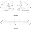
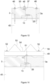
- the portion of the assembly 2 comprising the main tenon 13 of the first panel 3 interlocked with the main mortise 20 of the second panel 3a is called an interlocking area 47 of the two panels 3, 3a and is depicted in figure 12 .
- the fire resistance of the panel assembly is greatly improved.
- the specifically designed tenon and mortise greatly improve the static and dynamic loads of the panel assembly, and in particular the resistance to wind suction and the resistance to snow load.
- the mechanical resistance of the panel assembly is further improved.
- the second panel 3a is fastened to the building structure 45 with an appropriate fastener 46 as described above in relation with the first panel 3.
- the two panels 3, 3a are further bound by driving at least one stitching fastener 48 consecutively through the outer metallic sheet of the first panel, in particular through the outer central part of the first panel, and through the secondary mortise 30 of the first panel and the secondary tenon 37 of the second panel. Consequently, once the fastener has been inserted, the two panels 3, 3a are further bound by means of at least one stitching fastener 48 whose head lies on the outer metallic sheet, in particular on the outer central part, of the first panel and whose body goes through the outer metallic sheet, in particular on the outer central part, of the first panel and through the secondary mortise 30 of the first panel and the secondary tenon 37 of the second panel.
- the fire resistance of the panel assembly is further improved.
- the stitching of the two panels is preferably done with stitching fasteners regularly spaced. More preferably, the fastener spacing is between 250mm and 500mm.
- more than two panels 3 may be bounded together in order to form a bigger assembly of panels 2, provided that said assembly 2 extends into the plane P. More broadly for an assembly of panels 2 comprising n panels 3, the k th panel is first bounded to the k-1 th panel that is already fastened to the building structure 45. Then the k th panel is fastened to the building structure 45. The operation is repeated for the following panels 3 until the n th panel is bounded to the n-1 th panel and fastened to the building structure 45.
- At least one metallic profile 49 is at least partially positioned on at least a part of the assembly of panels 2.
- it is at least partially positioned on at least a part of the outer central parts 26 of the outer metallic sheets of the first and second panels. More precisely, it is at least partially positioned on a part of the assembly of panels 2 comprising the interlocked main tenon 13 and main mortise 20 of the different panels 3. In other words, it is at least partially positioned on the interlocking area 47 of the assembly of panels 2.
- the metallic profile 49 is fastened to the assembly of panels 2.
- the metallic profiles 49 can be notably metallic sheet profiles, as part of an external facing, thin profiles used as spacers between the assembly of panels and an external facing or thin profiles used as spacers between the assembly of panels and photovoltaic modules.
- the metallic profiles 49 can be thin profiles used as spacers between the assembly of panels and an external facing 50. They have preferably the shape of an omega and comprise two opposite legs and a U-shaped central portion. This U-shaped central portion comprises a plane base and two branches extending from the opposite ends of the plane base. The angle between each branch and the plane base is preferably comprised between 100 and 130 degrees, which represents a good compromise between stiffness and stacking capability.
- the metallic profiles 49 are regularly spaced and extend perpendicularly to the longitudinal axis X of each panel 3. In other words, the metallic profiles are parallel to each other and extend perpendicularly to the longitudinal edges 7 of the panels 3 (see Figure 1 ). As depicted in Figure 1 , and in a non-limitative manner, the length of the metallic profile 49 is about three times the width of each panel 3. In addition, and in order to optimally strengthen the assembly comprising three panels 3, the building envelope 1 comprises five metallic profiles 49 regularly and longitudinally spaced.
- the metallic profiles 49 can be thin profiles used as spacers between the assembly of panels and photovoltaic modules 57, such as rails, extruded or not. They can have various forms and shapes and the man skilled in the art will know which profile has to be selected for a specific installation.
- Each metallic profile 49 is fastened to the assembly of panels 2 with a plurality of profile fasteners 51, for example screws.
- the profile fastener is inserted from the front face of the panel, i.e. it is driven consecutively through the outer metallic sheet 5 of the second panel 3a, in particular through the outer central part of the second panel, and through the main tenon 13 of first panel 3 and the main mortise 20 of the second panel 3a.
- the profile fastener 51 will penetrate five steel layers of the panels 3, 3a, thus providing better pull out resistance. Moreover, the profile fasteners 51 act as stitching screws and further prevent the opening of the main tenon / main mortise interlock during fire.
- an external facing 50 is provided and fastened to the metallic profiles 49.
- this external facing 50 is a corrugated metallic sheet panel with a periodic pattern comprising a decorative section 53 and a fastening section 54.
- the decorative section 53 is chevron-shaped while the fastening section 54 is a rectangular plane base.
- a first longitudinal edge of the rectangular plane base 54 extends from a longitudinal edge of the chevron-shape section 53, while a second opposite longitudinal edge of the rectangular plane based 54 extends from a longitudinal edge of the chevron-shape section 53 of an adjacent periodic pattern.
- Both the rectangular plane base 54 and the chevron-shaped section 53 of each periodic pattern are extending perpendicularly to the longitudinal edges of the panels 3.
- the external facing 50 is fastened, with facing fasteners 52, for example screws, to the metallic profiles 49, in particular to the plane base of the U-shaped central portion of the metallic profiles.
- the static and dynamic loads of the suspended façade are significantly increased, and in particular the resistance to wind suction. It notably allows the installation of external facings with very heavy self-weight, such as terracotta.
- photovoltaic modules 57 are provided and fastened to the metallic profiles 49.
Landscapes
- Engineering & Computer Science (AREA)
- Architecture (AREA)
- Civil Engineering (AREA)
- Structural Engineering (AREA)
- Physics & Mathematics (AREA)
- Electromagnetism (AREA)
- Building Environments (AREA)
- Roof Covering Using Slabs Or Stiff Sheets (AREA)
Claims (14)
- Gebäude, umfassend eine Gebäudestruktur und eine Anordnung (2) aus mindestens einer ersten Platte und einer zweiten Platte (3), die sich jeweils entlang einer Längsachse X erstrecken, und eine innere Metallschale (4), ein äußeres Metallblech (5) und ein Isoliermaterial (6), das zwischen die innere Metallschale (4) und das äußere Metallblech (5) eingefügt ist, und umfassend eine erste Längsseite (9) und eine zweite Längsseite (10), wobei die innere Metallschale im Querschnitt senkrecht zur Längsachse verläuft und Folgendes umfasst:- ein inneres Mittelteil (11), das im Wesentlichen in einer Ebene P liegt,- einen ersten inneren Flansch (12), der sich von einem ersten Ende des inneren Mittelteils entlang der ersten Längsseite des Isoliermaterials erstreckt und eine U-förmige Biegung umfasst, die einen Hauptzapfen (13) bildet, der sich parallel zu der Ebene P und nach außen erstreckt,- einen zweiten inneren Flansch (19), der sich von einem zweiten, gegenüberliegenden Ende des inneren Mittelteils entlang der zweiten Längsseite des Isoliermaterials erstreckt und eine U-förmige Biegung umfasst, die ein Hauptzapfenloch (20) bildet, das sich parallel zu der Ebene P und nach innen erstreckt, wobei der Hauptzapfen und das Hauptzapfenloch Formen aufweisen, die ihr Ineinandergreifen ermöglichen,wobei das äußere Metallblech (5) in einem Querschnitt senkrecht zu der Längsachse Folgendes umfasst:- ein äußeres Mittelteil (26),- einen ersten äußeren Flansch (29), der sich von einem ersten Ende des äußeren Mittelteils entlang der ersten Längsseite des Isoliermaterials erstreckt und eine U-förmige Biegung umfasst, die ein sekundäres Zapfenloch (30) bildet, das sich nach innen und parallel zu dem Hauptzapfen erstreckt,- einen zweiten äußeren Flansch (36), der sich von einem zweiten gegenüberliegenden Ende des äußeren Mittelteils entlang der zweiten Längsseite des Isoliermaterials erstreckt und eine U-förmige Biegung umfasst, die einen sekundären Zapfen (37) bildet, der sich nach außen und parallel zu dem Hauptzapfenloch erstreckt, wobei der sekundäre Zapfen und das sekundäre Zapfenloch Formen aufweisen, die ihr Ineinandergreifen ermöglichen,wobei die erste bzw. zweite Platte mit ersten Befestigungselementen (46), deren Köpfe auf dem äußeren Mittelteil (26) der äußeren Metallplatte der ersten bzw. zweiten Platte liegen und deren Körper durch das äußere Mittelteil (26) und durch das innere Mittelteil (11) der inneren Metallplatte der ersten bzw. zweiten Platte verlaufen, mit der Gebäudestruktur verbunden ist, die an die innere Metallplatte der ersten bzw. zweiten Platte angrenzt, das Gebäude ferner umfassend ein Metallprofil (49), das zumindest teilweise auf zumindest einem Teil der äußeren Mittelteile (26) der äußeren Metallbleche der ersten und der zweiten Platte positioniert ist und mit einem zweiten Befestigungselement (51), dessen Körper durch den äußeren Mittelteil (26) des äußeren Metallblechs der zweiten Platte verläuft, an der Gesamtheit der Platten befestigt ist, wobei das Gebäude dadurch gekennzeichnet ist, dassdie erste und die zweite Platte durch Folgendes befestigt sind:- die Verriegelung des Hauptzapfens (13) der ersten Platte mit dem Hauptzapfenloch der zweiten Platte (20),- die Verriegelung des sekundären Zapfenlochs (30) der ersten Platte mit dem sekundären Zapfen (37) der zweiten Platte,und dass das zweite Befestigungselement (51) durch den Hauptzapfen (13) der ersten Platte und das Hauptzapfenloch (20) der zweiten Platte verläuft.
- Gebäude nach Anspruch 1, wobei die Basis des Hauptzapfens (13) und die Basis des sekundären Zapfenlochs (30) in einer Ebene senkrecht zu der Ebene P ausgerichtet sind.
- Gebäude nach einem der Ansprüche 1 oder 2, wobei sich der Hauptzapfen (13) nach außen über eine Ebene hinaus erstreckt, die senkrecht zu der Ebene P ist und das erste Ende des äußeren Mittelteils (26) bildet.
- Gebäude nach einem der vorherigen Ansprüche, wobei die Basis des Hauptzapfenlochs (20) und die Basis des sekundären Zapfens (37) in einer Ebene senkrecht zur Ebene P ausgerichtet sind.
- Bauwerk nach einem der vorherigen Ansprüche, wobei sich das Hauptzapfenloch (20) nach innen über eine Ebene senkrecht zu der Ebene P erstreckt und das zweite Ende des äußeren Mittelteils (26) umfasst.
- Gebäude nach einem der vorherigen Ansprüche, wobei das äußere Mittelteil (26) eine Längsrippe (27) angrenzend an das zweite Ende des äußeren Mittelteils umfasst.
- Gebäude nach Anspruch 6, wobei sich das Hauptzapfenloch (20) unterhalb der Längsrippe (27) erstreckt.
- Gebäude nach einem der vorherigen Ansprüche, wobei die erste Platte und die zweite Platte (3) ferner durch mindestens ein Heftungselement (48) verbunden sind, dessen Körper durch das sekundäre Zapfenloch (30) der ersten Platte und den sekundären Zapfen (37) der zweiten Platte verläuft.
- Gebäude nach einem der vorherigen Ansprüche, wobei sich das Metallprofil senkrecht zu der Längsachse X der Platten erstreckt.
- Gebäude nach einem der vorherigen Ansprüche, wobei das Metallprofil (49) ein Metallblechprofil ist.
- Gebäude nach einem der Ansprüche 1 bis 9, wobei das Metallprofil (49) ein Profil ist, das als Abstandhalter zwischen der Plattenanordnung (2) und einer Außenverkleidung (50) verwendet werden soll und kann.
- Gebäude nach Anspruch 11, ferner umfassend eine Außenverkleidung (50), die an dem Metallprofil (49) befestigt ist.
- Gebäude nach einem der Ansprüche 1 bis 9, wobei das Metallprofil (49) ein Profil ist, das als Abstandhalter zwischen der Plattenanordnung (2) und Solarmodulen (57) verwendet werden soll und kann.
- Verfahren zum Zusammenbau eines Gebäudes nach einem der Ansprüche 1 bis 13, umfassend:- (i) Bereitstellen einer ersten Platte (3) und einer zweiten Platte (3),- (ii) Befestigen der ersten und der zweiten Platte (3) an einer Gebäudestruktur (45), sodass sie eine Anordnung von Platten (2) bilden, wobei der Schritt (ii) die folgenden Teilschritte umfasst:o Positionieren der inneren Metallschale (4) der ersten Platte (3) angrenzend an die Gebäudestruktur (45),o Befestigen der ersten Platte an der Gebäudestruktur durch Eintreiben eines ersten Befestigungselements (46) durch das äußere Metallblech (5) und die innere Metallschale der ersten Platte, wobei das Verfahren dadurch gekennzeichnet ist, dass es die folgenden weiteren Schritte umfasst:o Positionieren der inneren Metallschale (4) der zweiten Platte (3) angrenzend an die Gebäudestruktur, sodass die zwei Platten miteinander verbunden sind:▪ Ineinandergreifen des Hauptzapfens (13) der ersten Platte mit dem Hauptzapfenloch der zweiten Platte (20),▪ Ineinandergreifen des sekundären Zapfenlochs (30) der ersten Platte mit dem sekundären Zapfen (37) der zweiten Platte,o Befestigen der zweiten Platte an der Gebäudestruktur, indem ein Befestigungselement (46) nacheinander durch das äußere Metallblech und die innere Metallschale der zweiten Platte getrieben wird,- (iii) Positionieren mindestens eines Metallprofils (49) auf mindestens einem Teil der Plattenanordnung (2) und Befestigen desselben an der Plattenanordnung mit einem zweiten Befestigungselement (51), dessen Körper durch das äußere Mittelteil (26) des äußeren Metallblechs der zweiten Platte, den Hauptzapfen (13) der ersten Platte und das Hauptzapfenloch (20) der zweiten Platte verläuft.
Applications Claiming Priority (2)
| Application Number | Priority Date | Filing Date | Title |
|---|---|---|---|
| PCT/IB2020/055240 WO2021245443A1 (en) | 2020-06-03 | 2020-06-03 | Building envelope |
| PCT/IB2021/054794 WO2021245550A1 (en) | 2020-06-03 | 2021-06-01 | Building envelope |
Publications (2)
| Publication Number | Publication Date |
|---|---|
| EP4162123A1 EP4162123A1 (de) | 2023-04-12 |
| EP4162123B1 true EP4162123B1 (de) | 2025-04-30 |
Family
ID=71108650
Family Applications (1)
| Application Number | Title | Priority Date | Filing Date |
|---|---|---|---|
| EP21729036.0A Active EP4162123B1 (de) | 2020-06-03 | 2021-06-01 | Gebäudehülle |
Country Status (4)
| Country | Link |
|---|---|
| EP (1) | EP4162123B1 (de) |
| ES (1) | ES3035606T3 (de) |
| PL (1) | PL4162123T3 (de) |
| WO (2) | WO2021245443A1 (de) |
Families Citing this family (1)
| Publication number | Priority date | Publication date | Assignee | Title |
|---|---|---|---|---|
| WO2025125862A1 (en) * | 2023-12-12 | 2025-06-19 | Arcelormittal | Sandwich panel and building envelope thereof |
Family Cites Families (6)
| Publication number | Priority date | Publication date | Assignee | Title |
|---|---|---|---|---|
| US5373678A (en) * | 1994-02-22 | 1994-12-20 | Hesser; Francis J. | Structural panel system |
| US8631620B2 (en) * | 2006-01-20 | 2014-01-21 | Centria | Advanced building envelope delivery system and method |
| AU2008242134A1 (en) | 2007-04-18 | 2008-10-30 | Kingspan Research And Developments Limited | A cladding panel |
| EP2169129B1 (de) * | 2008-09-26 | 2016-06-08 | Jean-Pierre Gingras | Verbindungsklammer für modulare Tafeln |
| CA2801052C (en) * | 2010-06-08 | 2018-09-25 | Kingspan Holdings (Irl) Limited | A structural infill wall panel module |
| US10590646B2 (en) * | 2018-01-24 | 2020-03-17 | Wall Technologies Pty Ltd. | Composite building panel and shell |
-
2020
- 2020-06-03 WO PCT/IB2020/055240 patent/WO2021245443A1/en not_active Ceased
-
2021
- 2021-06-01 ES ES21729036T patent/ES3035606T3/es active Active
- 2021-06-01 WO PCT/IB2021/054794 patent/WO2021245550A1/en not_active Ceased
- 2021-06-01 EP EP21729036.0A patent/EP4162123B1/de active Active
- 2021-06-01 PL PL21729036.0T patent/PL4162123T3/pl unknown
Also Published As
| Publication number | Publication date |
|---|---|
| ES3035606T3 (en) | 2025-09-05 |
| PL4162123T3 (pl) | 2025-06-23 |
| WO2021245443A1 (en) | 2021-12-09 |
| EP4162123A1 (de) | 2023-04-12 |
| WO2021245550A1 (en) | 2021-12-09 |
Similar Documents
| Publication | Publication Date | Title |
|---|---|---|
| US8387325B2 (en) | Insulated siding apparatus | |
| US20120231231A1 (en) | Composite panel | |
| WO2004009929A1 (en) | Insulating panel with outer reinforcing sections | |
| US7603822B2 (en) | Panelized wall system with foam core insulation | |
| WO2020115657A1 (en) | Sandwich panel assembly and associated building | |
| EP4162123A1 (de) | Gebäudehülle | |
| EP1570141B1 (de) | Flaches Dach oder wesentlich flaches Dach | |
| CA2695884A1 (en) | Insulated siding apparatus | |
| WO2021229273A1 (en) | Building envelope and process for its assembling | |
| KR102537166B1 (ko) | 용마루와 지붕 패널의 틈새를 밀폐하기 위한 마감 부재, 그 제조 방법 및 마감 부재를 포함하는 건축 구조물 | |
| CA3085505C (en) | Sandwich panel and associated assembly method | |
| US12209406B2 (en) | Facade element, building facade and process for the assembling of such a building facade | |
| AU2013101367A4 (en) | A building panel | |
| CA3160630C (en) | Facade element, building facade and process for the assembling of such a building facade | |
| WO2009027958A1 (en) | A composite panel | |
| KR101368011B1 (ko) | 벽 구조물 | |
| CN220184423U (zh) | 一种建筑保温隔热墙板 | |
| FI123601B (fi) | Seinärakenne ja menetelmä seinärakenteen valmistamiseksi | |
| WO2002095162A1 (en) | Brick slip fixture system | |
| RU2323306C2 (ru) | Крепежная скоба для стеновых материалов и изоляционная стеновая конструкция | |
| WO2024095039A1 (en) | Composite floor deck member and assembly thereof | |
| JP2002129708A (ja) | 断熱屋根パネル及び断熱屋根パネルの接続構造 | |
| RU2305736C1 (ru) | Конструкция ограждения с теплоизоляцией и декоративной отделкой фасадов, фасадная панель (варианты) и нащельная планка (варианты) для нее | |
| JPH02176065A (ja) | サンドイッチパネル | |
| HU188501B (en) | Bilding covering member and side closing tool for producing same |
Legal Events
| Date | Code | Title | Description |
|---|---|---|---|
| STAA | Information on the status of an ep patent application or granted ep patent |
Free format text: STATUS: UNKNOWN |
|
| STAA | Information on the status of an ep patent application or granted ep patent |
Free format text: STATUS: THE INTERNATIONAL PUBLICATION HAS BEEN MADE |
|
| PUAI | Public reference made under article 153(3) epc to a published international application that has entered the european phase |
Free format text: ORIGINAL CODE: 0009012 |
|
| STAA | Information on the status of an ep patent application or granted ep patent |
Free format text: STATUS: REQUEST FOR EXAMINATION WAS MADE |
|
| 17P | Request for examination filed |
Effective date: 20230103 |
|
| AK | Designated contracting states |
Kind code of ref document: A1 Designated state(s): AL AT BE BG CH CY CZ DE DK EE ES FI FR GB GR HR HU IE IS IT LI LT LU LV MC MK MT NL NO PL PT RO RS SE SI SK SM TR |
|
| DAV | Request for validation of the european patent (deleted) | ||
| DAX | Request for extension of the european patent (deleted) | ||
| GRAP | Despatch of communication of intention to grant a patent |
Free format text: ORIGINAL CODE: EPIDOSNIGR1 |
|
| STAA | Information on the status of an ep patent application or granted ep patent |
Free format text: STATUS: GRANT OF PATENT IS INTENDED |
|
| RIC1 | Information provided on ipc code assigned before grant |
Ipc: E04C 2/00 20060101ALN20241113BHEP Ipc: E04C 2/32 20060101ALI20241113BHEP Ipc: E04C 2/292 20060101ALI20241113BHEP Ipc: E04B 2/92 20060101ALI20241113BHEP Ipc: E04F 13/12 20060101ALI20241113BHEP Ipc: E04F 13/08 20060101AFI20241113BHEP |
|
| INTG | Intention to grant announced |
Effective date: 20241212 |
|
| GRAS | Grant fee paid |
Free format text: ORIGINAL CODE: EPIDOSNIGR3 |
|
| GRAA | (expected) grant |
Free format text: ORIGINAL CODE: 0009210 |
|
| STAA | Information on the status of an ep patent application or granted ep patent |
Free format text: STATUS: THE PATENT HAS BEEN GRANTED |
|
| AK | Designated contracting states |
Kind code of ref document: B1 Designated state(s): AL AT BE BG CH CY CZ DE DK EE ES FI FR GB GR HR HU IE IS IT LI LT LU LV MC MK MT NL NO PL PT RO RS SE SI SK SM TR |
|
| P01 | Opt-out of the competence of the unified patent court (upc) registered |
Free format text: CASE NUMBER: APP_14657/2025 Effective date: 20250326 |
|
| REG | Reference to a national code |
Ref country code: CH Ref legal event code: EP Ref country code: GB Ref legal event code: FG4D |
|
| REG | Reference to a national code |
Ref country code: IE Ref legal event code: FG4D |
|
| REG | Reference to a national code |
Ref country code: DE Ref legal event code: R096 Ref document number: 602021030007 Country of ref document: DE |
|
| PGFP | Annual fee paid to national office [announced via postgrant information from national office to epo] |
Ref country code: NL Payment date: 20250520 Year of fee payment: 5 |
|
| REG | Reference to a national code |
Ref country code: SE Ref legal event code: TRGR |
|
| REG | Reference to a national code |
Ref country code: NL Ref legal event code: FP |
|
| PGFP | Annual fee paid to national office [announced via postgrant information from national office to epo] |
Ref country code: PL Payment date: 20250521 Year of fee payment: 5 Ref country code: DE Payment date: 20250520 Year of fee payment: 5 |
|
| PGFP | Annual fee paid to national office [announced via postgrant information from national office to epo] |
Ref country code: GB Payment date: 20250520 Year of fee payment: 5 |
|
| PGFP | Annual fee paid to national office [announced via postgrant information from national office to epo] |
Ref country code: NO Payment date: 20250522 Year of fee payment: 5 |
|
| PGFP | Annual fee paid to national office [announced via postgrant information from national office to epo] |
Ref country code: LU Payment date: 20250523 Year of fee payment: 5 Ref country code: BE Payment date: 20250520 Year of fee payment: 5 Ref country code: IT Payment date: 20250530 Year of fee payment: 5 |
|
| PGFP | Annual fee paid to national office [announced via postgrant information from national office to epo] |
Ref country code: FR Payment date: 20250520 Year of fee payment: 5 |
|
| PGFP | Annual fee paid to national office [announced via postgrant information from national office to epo] |
Ref country code: AT Payment date: 20250721 Year of fee payment: 5 |
|
| PGFP | Annual fee paid to national office [announced via postgrant information from national office to epo] |
Ref country code: SE Payment date: 20250520 Year of fee payment: 5 |
|
| REG | Reference to a national code |
Ref country code: SK Ref legal event code: T3 Ref document number: E 46675 Country of ref document: SK |
|
| REG | Reference to a national code |
Ref country code: ES Ref legal event code: FG2A Ref document number: 3035606 Country of ref document: ES Kind code of ref document: T3 Effective date: 20250905 |
|
| PG25 | Lapsed in a contracting state [announced via postgrant information from national office to epo] |
Ref country code: FI Free format text: LAPSE BECAUSE OF FAILURE TO SUBMIT A TRANSLATION OF THE DESCRIPTION OR TO PAY THE FEE WITHIN THE PRESCRIBED TIME-LIMIT Effective date: 20250430 Ref country code: PT Free format text: LAPSE BECAUSE OF FAILURE TO SUBMIT A TRANSLATION OF THE DESCRIPTION OR TO PAY THE FEE WITHIN THE PRESCRIBED TIME-LIMIT Effective date: 20250901 |
|
| PGFP | Annual fee paid to national office [announced via postgrant information from national office to epo] |
Ref country code: ES Payment date: 20250701 Year of fee payment: 5 |
|
| REG | Reference to a national code |
Ref country code: LT Ref legal event code: MG9D |
|
| PG25 | Lapsed in a contracting state [announced via postgrant information from national office to epo] |
Ref country code: GR Free format text: LAPSE BECAUSE OF FAILURE TO SUBMIT A TRANSLATION OF THE DESCRIPTION OR TO PAY THE FEE WITHIN THE PRESCRIBED TIME-LIMIT Effective date: 20250731 |
|
| PG25 | Lapsed in a contracting state [announced via postgrant information from national office to epo] |
Ref country code: BG Free format text: LAPSE BECAUSE OF FAILURE TO SUBMIT A TRANSLATION OF THE DESCRIPTION OR TO PAY THE FEE WITHIN THE PRESCRIBED TIME-LIMIT Effective date: 20250430 |
|
| PG25 | Lapsed in a contracting state [announced via postgrant information from national office to epo] |
Ref country code: HR Free format text: LAPSE BECAUSE OF FAILURE TO SUBMIT A TRANSLATION OF THE DESCRIPTION OR TO PAY THE FEE WITHIN THE PRESCRIBED TIME-LIMIT Effective date: 20250430 |
|
| PG25 | Lapsed in a contracting state [announced via postgrant information from national office to epo] |
Ref country code: RS Free format text: LAPSE BECAUSE OF FAILURE TO SUBMIT A TRANSLATION OF THE DESCRIPTION OR TO PAY THE FEE WITHIN THE PRESCRIBED TIME-LIMIT Effective date: 20250731 |
|
| PGFP | Annual fee paid to national office [announced via postgrant information from national office to epo] |
Ref country code: CZ Payment date: 20250528 Year of fee payment: 5 |
|
| PGFP | Annual fee paid to national office [announced via postgrant information from national office to epo] |
Ref country code: SK Payment date: 20250526 Year of fee payment: 5 |
|
| PG25 | Lapsed in a contracting state [announced via postgrant information from national office to epo] |
Ref country code: IS Free format text: LAPSE BECAUSE OF FAILURE TO SUBMIT A TRANSLATION OF THE DESCRIPTION OR TO PAY THE FEE WITHIN THE PRESCRIBED TIME-LIMIT Effective date: 20250830 |
|
| PG25 | Lapsed in a contracting state [announced via postgrant information from national office to epo] |
Ref country code: LV Free format text: LAPSE BECAUSE OF FAILURE TO SUBMIT A TRANSLATION OF THE DESCRIPTION OR TO PAY THE FEE WITHIN THE PRESCRIBED TIME-LIMIT Effective date: 20250430 |
|
| PG25 | Lapsed in a contracting state [announced via postgrant information from national office to epo] |
Ref country code: DK Free format text: LAPSE BECAUSE OF FAILURE TO SUBMIT A TRANSLATION OF THE DESCRIPTION OR TO PAY THE FEE WITHIN THE PRESCRIBED TIME-LIMIT Effective date: 20250430 Ref country code: SM Free format text: LAPSE BECAUSE OF FAILURE TO SUBMIT A TRANSLATION OF THE DESCRIPTION OR TO PAY THE FEE WITHIN THE PRESCRIBED TIME-LIMIT Effective date: 20250430 |
|
| PG25 | Lapsed in a contracting state [announced via postgrant information from national office to epo] |
Ref country code: EE Free format text: LAPSE BECAUSE OF FAILURE TO SUBMIT A TRANSLATION OF THE DESCRIPTION OR TO PAY THE FEE WITHIN THE PRESCRIBED TIME-LIMIT Effective date: 20250430 |
|
| REG | Reference to a national code |
Ref country code: CH Ref legal event code: H13 Free format text: ST27 STATUS EVENT CODE: U-0-0-H10-H13 (AS PROVIDED BY THE NATIONAL OFFICE) Effective date: 20260127 |
|
| PG25 | Lapsed in a contracting state [announced via postgrant information from national office to epo] |
Ref country code: MC Free format text: LAPSE BECAUSE OF FAILURE TO SUBMIT A TRANSLATION OF THE DESCRIPTION OR TO PAY THE FEE WITHIN THE PRESCRIBED TIME-LIMIT Effective date: 20250430 |
|
| REG | Reference to a national code |
Ref country code: DE Ref legal event code: R097 Ref document number: 602021030007 Country of ref document: DE |
|
| PG25 | Lapsed in a contracting state [announced via postgrant information from national office to epo] |
Ref country code: RO Free format text: LAPSE BECAUSE OF FAILURE TO SUBMIT A TRANSLATION OF THE DESCRIPTION OR TO PAY THE FEE WITHIN THE PRESCRIBED TIME-LIMIT Effective date: 20250430 |
|
| PLBE | No opposition filed within time limit |
Free format text: ORIGINAL CODE: 0009261 |
|
| STAA | Information on the status of an ep patent application or granted ep patent |
Free format text: STATUS: NO OPPOSITION FILED WITHIN TIME LIMIT |
|
| REG | Reference to a national code |
Ref country code: CH Ref legal event code: L10 Free format text: ST27 STATUS EVENT CODE: U-0-0-L10-L00 (AS PROVIDED BY THE NATIONAL OFFICE) Effective date: 20260311 |
|
| 26N | No opposition filed |
Effective date: 20260202 |
|
| PG25 | Lapsed in a contracting state [announced via postgrant information from national office to epo] |
Ref country code: IE Free format text: LAPSE BECAUSE OF NON-PAYMENT OF DUE FEES Effective date: 20250601 |
|
| PG25 | Lapsed in a contracting state [announced via postgrant information from national office to epo] |
Ref country code: CH Free format text: LAPSE BECAUSE OF NON-PAYMENT OF DUE FEES Effective date: 20250630 |