EP4162188B1 - Dispositif pour connecter deux objets tubulaires - Google Patents
Dispositif pour connecter deux objets tubulaires Download PDFInfo
- Publication number
- EP4162188B1 EP4162188B1 EP21730132.4A EP21730132A EP4162188B1 EP 4162188 B1 EP4162188 B1 EP 4162188B1 EP 21730132 A EP21730132 A EP 21730132A EP 4162188 B1 EP4162188 B1 EP 4162188B1
- Authority
- EP
- European Patent Office
- Prior art keywords
- securing
- radially
- tabs
- recess
- connection piece
- Prior art date
- Legal status (The legal status is an assumption and is not a legal conclusion. Google has not performed a legal analysis and makes no representation as to the accuracy of the status listed.)
- Active
Links
Images
Classifications
-
- F—MECHANICAL ENGINEERING; LIGHTING; HEATING; WEAPONS; BLASTING
- F16—ENGINEERING ELEMENTS AND UNITS; GENERAL MEASURES FOR PRODUCING AND MAINTAINING EFFECTIVE FUNCTIONING OF MACHINES OR INSTALLATIONS; THERMAL INSULATION IN GENERAL
- F16L—PIPES; JOINTS OR FITTINGS FOR PIPES; SUPPORTS FOR PIPES, CABLES OR PROTECTIVE TUBING; MEANS FOR THERMAL INSULATION IN GENERAL
- F16L37/00—Couplings of the quick-acting type
- F16L37/08—Couplings of the quick-acting type in which the connection between abutting or axially overlapping ends is maintained by locking members
- F16L37/084—Couplings of the quick-acting type in which the connection between abutting or axially overlapping ends is maintained by locking members combined with automatic locking
- F16L37/098—Couplings of the quick-acting type in which the connection between abutting or axially overlapping ends is maintained by locking members combined with automatic locking by means of flexible hooks
- F16L37/0985—Couplings of the quick-acting type in which the connection between abutting or axially overlapping ends is maintained by locking members combined with automatic locking by means of flexible hooks the flexible hook extending radially inwardly from an outer part and engaging a bead, recess or the like on an inner part
Definitions
- the invention relates to a device for connecting two tubular objects according to the preamble of claim 1.
- Such devices are capable of connecting tubular objects to one another which have a predominantly rigid shape and are made of a solid material.
- a nozzle housing with a nozzle arranged thereon which can be inserted into one of the tubular objects.
- the other tubular object can be designed in the form of a nozzle or equipped with one. The latter is then inserted into a plug-in end of such a device and locked there.
- WO 2005/047753 A1 shows a coupling device for connecting two rigid, tubular objects, the device having a socket part, a plug part and a sleeve-shaped element that can be attached between them. Elastic tongues are provided for snapping the components together. Another device is made of US 2007/120362 A1 known.
- the object of the invention is to propose a device for connecting two tubular objects, in which locking can be ensured safely and without great effort and which can be manufactured as cost-effectively as possible.
- a device for connecting two tubular objects comprising a nozzle housing and a securing element, wherein the nozzle housing has a sleeve section with a receiving opening, wherein the securing element is shaped complementarily to the receiving opening and is rotatably arranged in the receiving opening and has an insertion opening for receiving a nozzle, wherein the securing element has securing tabs spaced apart from one another in the circumferential direction, each of which has a radially inwardly facing securing body for engaging in shape features of an inserted nozzle and can be moved from a first radial position into a radially outer second radial position.
- the nozzle housing has a radially inwardly bevelled ramp surface for each securing tab, on which the respective securing tab rests with a support surface, wherein the ramp surface and the support surface are shaped such that by rotating the securing element about a central axis of the nozzle housing in a first direction, the securing tabs are forced into the second radial position and the securing element is rotated back in an unloaded state by the securing tabs springing back into the first position in a second direction opposite to the first direction.
- the device is therefore designed to connect two tubular objects to one another, one of which can be coupled to the nozzle housing and the other has a connecting element, for example a nozzle, for insertion into the insertion opening of the securing element.
- a connecting element for example a nozzle
- other devices that can be formed on the nozzle housing are also conceivable.
- the design is not essential to the function of the device and should not be understood as a limitation in the following.
- the securing element is designed to secure the connecting element when plugged in, so that it cannot slip out of the securing element by itself, due to vibration, inertial forces or a fluid flowing through it or something similar.
- the connecting element could have one or more circumferential grooves on an outer surface into which the securing bodies of the securing tabs can penetrate in a radial direction. The connecting element is then secured in an axial direction.
- the securing element and the sleeve-shaped section are designed to complement each other in such a way that the securing element is preferably locked in the receiving opening or secured in another way.
- radial recesses could be provided in the nozzle housing into which parts of the securing tabs or elements connected to them protrude. This will be explained further below.
- the securing element could have a roughly ring- or sleeve-shaped base that has the insertion opening.
- the securing tabs can extend in the axial direction on a side of the securing element facing away from the insertion opening.
- the base of the securing element can be rotatably coupled to the nozzle housing, so that the securing tabs can be moved in the circumferential direction of the nozzle housing by rotating the securing element. It may be advisable to distribute two, three, four or more securing tabs around the circumference.
- the nozzle housing has a ramp surface on which a corresponding support surface of the securing tab rests.
- the ramp surface is bevelled radially inwards so that the support surface slides on the ramp surface when the securing element is rotated. Due to the radially inward bevel of the ramp surface, the rotation in the first direction and the resulting sliding cause the securing tabs to move radially outwards.
- the support surfaces press on the corresponding ramp surface and thereby rotate the securing element back in the opposite second direction. The securing tabs then return to the first position.
- the support surface and the sliding surface are designed in such a way that they allow unhindered rotation back.
- the particular advantage of the device according to the invention is that it enables easy assembly and disassembly of a nozzle in the insertion opening.
- a user only has to turn the securing element in the first direction so that the securing tabs are pushed radially outwards and the nozzle or another connecting element is released or can be inserted. Since the securing element is then turned back and the securing tabs are pushed back into the first radial position, the user does not have to carry out any further steps after inserting the connector. Consequently, the device according to the invention can be arranged on a connecting element of an assembly in order to then be connected to another tubular object in a final assembly. The design of the device can ensure that the device does not come loose from the connector. The assembly in question can therefore be assembled in a simplified manner.
- the automatic locking means that the device is always in a closed state, i.e. connected or not connected. It is therefore not possible for it to remain in an open state.
- the securing tabs are designed to be radially resilient.
- the radial resilience can be ensured by selecting a suitable plastic material.
- the securing tabs have a basic shape that the securing element assumes in an unloaded state. If the securing tabs are subjected to an outward radial force while sliding on the ramp surface, they can follow this force by making a radial evasive movement. It is sensible to design an area specifically for this purpose. As explained below, this area can be arranged at a free end of the securing tabs.
- the ramp surface has a radially outer first section and a radially inner second section, the first section being straight and the second section being radially more tapered inwards than the first section.
- the first section then has a flat surface that is straight throughout. In a plane that is perpendicular to the central axis of the nozzle housing, the first section therefore forms a straight line.
- the second section runs at an angle to this and is more tapered inwards. This means that the second section moves radially more inwards along the direction of travel of the ramp surface than the first section.
- the first section could define a directional axis in a plane perpendicular to the central axis, which passes the central axis.
- the first section could therefore define a circular segment on the nozzle housing, which has a central angle significantly below 180°.
- the angle of the first section with respect to a tangent which formed at the radially outer end of the ramp surface and located on a circumferential surface of the nozzle housing, could, for example, be significantly below 45°.
- the securing element has a radial recess for each securing tab, wherein the ramp surface is arranged in the recess and ends at a circumferential end of the recess.
- a recess is suitable for receiving a securing tab.
- the securing tab would then be at least partially able to be pushed radially outwards, whereby it then receives sufficient freedom of movement through the recess.
- the recess can also be designed in such a way that the device can be assembled by plugging the securing element and the nozzle housing together and the securing tab is held on the nozzle housing by suitable shape features.
- the ramp surface at the peripheral end forms a first angle to a first radius line which lies on a plane perpendicular to the central axis and extends centrally through the recess, the first angle being in a range of 72° to 74°.
- the first radius line could form a line of symmetry or a center line and extend centrally through the recess in the plane perpendicular to the central axis.
- the ramp surface is arranged at a peripheral end of the recess and the securing tab with the support surface must move towards this peripheral end so that the support surface is pushed radially outwards by the ramp surface.
- the choice of the first angle is dimensioned for the movement of the support surface radially outwards. In order to prevent tilting or jamming, the angle is selected to be in the range mentioned.
- a rounded transition section can preferably be arranged between the first section and the second section, which is tangent to the first section and the second section.
- the rounded transition section can carry out a transition of the support surface from the second to the first section. The sliding of the support surface on the ramp surface is improved by a rounded shape.
- the securing tabs can have a free end facing away from the insertion opening, on which the respective support surface is arranged. This enables the springing of the securing element and promotes or provides the radial movement of the support surface.
- the support surface has an inlet section and a transition section, wherein the inlet section is bevelled radially inwards and the transition section is radially is bevelled outwards.
- the transition section can create a harmonious transition to the inlet section.
- the inlet section comes into surface contact with the ramp surface and ensures the radial deflection.
- the inlet section and the transition section include a curved section which is tangent-continuously connected to the inlet section and the reset section.
- the tangent-continuous arrangement of the curved section prevents the securing tab from jamming and does not prevent an easier sliding movement.
- the inlet section is arranged on a peripheral boundary edge of the respective securing tab and forms a second angle to a second radius line which lies on a plane perpendicular to the central axis and extends centrally through the securing tab, the second angle being in a range of 55° to 65°.
- the second angle facilitates turning back to the first position.
- the transition section could also include a third angle with the second radius line, which is in a range of 73° to 80°.
- the securing tabs could extend radially outwards beyond the recess and act as an indicator element to show that the device is open. A user can immediately see that the device is not completely closed if part of the securing tab protrudes through the recess. This could, for example, indicate an incompletely inserted nozzle into which the securing bodies do not fully engage in the radial direction.
- the securing element can have at least one gripping element for initiating a rotation. This makes it much easier for a user to initiate the rotation by gripping the nozzle housing with one hand and the gripping element with the other hand, thus enabling rotation.
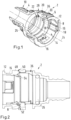
- Fig. 1 shows a device 2 for connecting two tubular objects in a partially sectioned, three-dimensional representation.
- the device 2 has a nozzle housing 4 and a securing element 12 which is inserted into the nozzle housing 4.
- the nozzle housing 4 has a sleeve section 6 with a receiving opening 8 into which the securing element 12 is inserted.
- the nozzle housing 4 has a nozzle section 10 which is provided, for example, with a groove-shaped profile which can wedge itself into the first tubular body.
- the securing element 12 is arranged rotatably in the receiving opening 8 and has an entry opening 14 for receiving a nozzle. This is inserted approximately in Fig. 4 shown.
- the securing element 12 also has securing tabs 16 spaced apart from one another in the circumferential direction, each of which has a radially inwardly facing securing body 18. These serve to engage in a complementarily shaped groove of a nozzle arranged in the insertion opening 14.
- the securing tabs 16 are also elastically deformable and can be moved from a first radial position (shown here) to a radially outer second radial position. A nozzle that is inserted into the insertion opening 14 could accordingly be locked into the securing bodies 18.
- the securing tabs 16 also each have a fixed end 30 and a free end 28. They are resilient overall, so that the free end 28 can be moved radially.
- the nozzle housing 4 has a ramp surface 20 for each securing tab 16 which is bevelled radially inwards.
- the respective securing tab 16 rests on the relevant ramp surface 20 with a radially inner support surface 22.
- the ramp surface 20 and the support surface 22 are shaped in such a way that by rotating the securing element 12 about a central axis 24 of the nozzle housing 4 in a first direction, the securing tabs 16 are pushed into the second radial position.
- the first direction corresponds to a clockwise rotation.
- the securing element 12 is in an unloaded state, i.e. when released and by the securing tab 16 springing back into the first position, it is rotated back in a second direction opposite to the first direction.
- the second direction therefore corresponds to a counterclockwise rotation.
- the device 2 is thus designed to release a nozzle located in the insertion opening 14 by rotating the securing element 12 in one direction and to automatically return to the locking state with the securing tabs 16 pivoted back radially inwards without any further action.
- the device 2 is therefore self-locking.
- the device 2 further comprises a sealing element in the form of a sealing ring 26, which is arranged in the nozzle housing 4 and is designed to come into flush contact with an end face of a nozzle inserted into the insertion opening 14. This seals the fluid connection between the nozzle and the nozzle section 10.
- Fig. 2 the device 2 is shown from a different perspective.
- the securing element 12 is not yet fully inserted into the receiving opening 8.
- the projections 48 of the securing tab 16 can be seen, each of which has a radially inwardly beveled inlet surface 50, which is complementary to a radially outwardly beveled guide surface 52 on the receiving opening 8.
- the securing tabs 16 are pushed radially inward, so that the projection 48 comes into a circumferential recess 36 of the nozzle housing 4 when the securing element 12 is fully inserted.
- the securing element 12 is thus mounted and can fulfill the function described above.
- the securing element 12 can have a type of stop ring 54 radially inside the projections 48, which limits a radially inward movement of the projections 48.
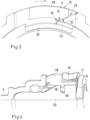
- Fig. 3 shows a detailed representation of a projection 48 of a securing tab 16, in which the support surface 22 rests on the ramp surface 20 of the nozzle housing 4. It can be seen there that the support surface 22 and the ramp surface 20 are shaped to correspond with one another. When the securing element 12 is rotated clockwise, the securing tab 16 moves radially outwards.
- Fig. 4 shows the securing element 12 in the inserted state in the socket housing 4.
- an inserted socket 56 which has a circumferential groove 58 as a shape feature. This is designed so that the securing body 18 of the securing tab 16 engages in the groove 58.
- the securing tab 16 is shown in the first position, ie radially inward. By turning the securing element 12, the projection 48 is moved radially outward so that the securing body 18 leaves the groove 58.
- This unlocked state is only maintained as long as a user rotates the locking element 12 in the first direction or holds it in the rotated position. As soon as the locking element 12 is released, the locking tabs 16 spring into the Fig. 4 shown state.
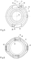
- a sectional view of the nozzle housing 4 is shown in a sectional plane perpendicular to the central axis 24, wherein the sectional plane runs adjacent to the ramp surface 20.
- a first angle ⁇ is shown, which is enclosed between the ramp surface 20 and a first radius line r1, which lies on a plane perpendicular to the central axis 24 and extends centrally through the recess 36.
- the first angle ⁇ is preferably in a range of 72-74°.
- the first radius line r1 is, however, a line of symmetry or a center line.
- the support surface 22 is designed as in Fig. 3 visible.
- the ramp surface 20 is arranged at a circumferential end 38 of the recess 36 and when the support surface 22 rests on the ramp surface 20, it must move in the direction of the circumferential end 38.
- the projection 48 is then pushed radially outwards by the surfaces 20 and 22 sliding on one another.
- the securing body 18 follows this movement and leaves the groove 58 of an inserted nozzle 56.
- Fig. 6 shows a top view of a front side of the securing element 12 facing the nozzle housing 4.
- the securing tab 16 and the projections 48 arranged thereon can be seen.
- two securing tabs 16 are arranged offset by 180° on the circumference.
- Two opposing grip elements 46 are arranged at a distance of 90° from each other on the circumference, with which a user can rotate the securing element 12.
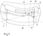
- FIG. 7 an enlarged view of a projection 48 with the support surface 22.
- This forms an inlet section 40, which is followed by a curved section 44 and a transition section 42.
- the transition section 42 can be chosen relatively arbitrarily.
- This has a third angle ⁇ , which encloses an angle in a range of 73° to 80° with the second radius line r2.
Landscapes
- Engineering & Computer Science (AREA)
- General Engineering & Computer Science (AREA)
- Mechanical Engineering (AREA)
- Quick-Acting Or Multi-Walled Pipe Joints (AREA)
- Mutual Connection Of Rods And Tubes (AREA)
Claims (10)
- Dispositif (2) pour relier deux objets tubulaires, le dispositif présentant un boîtier de raccordement (4) et un élément de fixation (12), le boîtier de raccordement (4) présentant une partie formant manchon (6) avec une ouverture de réception (8), l'élément de fixation (12) ayant une forme complémentaire à celle de l'ouverture de réception (8) et étant agencé de manière à être apte à tourner dans l'ouverture de réception (8) et présentant une ouverture d'insertion (14) pour recevoir une partie de raccordement (56), l'élément de fixation (12) présentant des pattes de fixation (16) espacées les unes des autres dans la direction circonférentielle, qui présentent chacune un corps de fixation (18) tourné radialement vers l'intérieur pour s'engager dans des zones (58) à forme caractéristique d'une partie de raccordement (56) insérée et qui sont aptes à être déplacées d'une première position radiale dans une deuxième position radiale située radialement à l'extérieur, le boîtier de raccordement (4) présentant pour chaque patte de fixation (16) une surface (20) en forme de rampe biseautée radialement vers l'intérieur, sur laquelle repose la patte de fixation (16) respective par une surface d'appui (22), la surface (20) en forme de rampe et la surface d'appui (22) étant formées de telle manière que, par rotation de l'élément de fixation (12) autour d'un axe central (24) du boîtier de raccordement (4) dans une première direction, les pattes de fixation (16) sont poussées dans la deuxième position radiale, et l'élément de fixation (12), dans un état non sollicité, est ramené par élasticité des pattes de fixation (16) dans la première position selon une deuxième direction opposée à la première direction, caractérisé en ce que la surface d'appui (22) présente une portion d'entrée (40) et une portion de transition (42), la portion d'entrée (40) étant biseautée radialement vers l'intérieur et la portion de transition (42) étant biseautée radialement vers l'extérieur, la portion d'entrée (40) étant agencée sur un bord de délimitation périphérique de la patte de fixation (16) concernée et formant un deuxième angle (β) par rapport à une deuxième ligne de rayon (r2) qui se trouve sur un plan perpendiculaire à l'axe central (24) et qui s'étend au centre de la patte de fixation (16), le deuxième angle (β) étant situé dans une gamme allant de 55° à 65°.
- Dispositif (2) selon la revendication 1, caractérisé en ce que les pattes de fixation (16) sont conçues de façon à être élastiques radialement.
- Dispositif (2) selon la revendication 1 ou la revendication 2, caractérisé en ce que la surface (20) formant rampe présente une première portion (21) radialement extérieure et une deuxième portion (35) radialement intérieure, la première portion (21) étant rectiligne et la deuxième portion (35) étant radialement plus inclinée vers l'intérieur que la première portion (21) .
- Dispositif (2) selon l'une des revendications précédentes, caractérisé en ce que le boîtier de raccordement (4) comporte un évidement radial (36) pour chaque patte de fixation (16), la surface (20) formant rampe étant agencée dans l'évidement (36) et se terminant à une extrémité périphérique (38) de l'évidement (36).
- Dispositif (2) selon la revendication 4, caractérisé en ce que la surface (20) formant rampe forme, à l'extrémité périphérique (38), un premier angle (α) par rapport à une première ligne de rayon (r1) située dans un plan perpendiculaire à l'axe central (24) et s'étendant centralement à travers l'évidement (36), le premier angle (α) étant compris dans une gamme allant de 72° à 74°.
- Dispositif (2) selon la revendication 3, caractérisé en ce qu'une portion de transition arrondie (34) est aménagée entre la première portion (21) et la deuxième portion (35), laquelle se raccorde à la première portion (21) et à la deuxième portion (35) de manière tangentielle.
- Dispositif (2) selon l'une des revendications précédentes, caractérisé en ce que les pattes de fixation (16) présentent une extrémité libre (28) opposée à l'ouverture d'insertion (14), sur laquelle est aménagée la surface d'appui (22) correspondante.
- Dispositif (2) selon l'une des revendications précédentes, caractérisé en ce que la portion d'entrée (40) et la portion de transition (42) comprennent une portion courbée (44) qui se raccorde de manière tangentielle à la portion d'entrée (40) et à la portion de transition (42).
- Dispositif (2) selon la revendication 4, caractérisé en ce que, dans la deuxième position, les pattes de fixation (16) dépassent radialement vers l'extérieur au-delà de l'évidement (36) et font office d'élément indicateur pour indiquer un dispositif ouvert.
- Dispositif (2) selon l'une des revendications précédentes, caractérisé en ce que l'élément de fixation (12) présente au moins un élément de préhension (46) pour initier une rotation.
Applications Claiming Priority (2)
| Application Number | Priority Date | Filing Date | Title |
|---|---|---|---|
| DE102020115021.0A DE102020115021A1 (de) | 2020-06-05 | 2020-06-05 | Vorrichtung zum Verbinden zweier röhrenförmiger Objekte |
| PCT/EP2021/064112 WO2021244925A1 (fr) | 2020-06-05 | 2021-05-26 | Dispositif pour relier deux objets tubulaires |
Publications (2)
| Publication Number | Publication Date |
|---|---|
| EP4162188A1 EP4162188A1 (fr) | 2023-04-12 |
| EP4162188B1 true EP4162188B1 (fr) | 2025-01-01 |
Family
ID=76283706
Family Applications (1)
| Application Number | Title | Priority Date | Filing Date |
|---|---|---|---|
| EP21730132.4A Active EP4162188B1 (fr) | 2020-06-05 | 2021-05-26 | Dispositif pour connecter deux objets tubulaires |
Country Status (9)
| Country | Link |
|---|---|
| US (1) | US12129950B2 (fr) |
| EP (1) | EP4162188B1 (fr) |
| JP (1) | JP7542084B2 (fr) |
| KR (1) | KR102779978B1 (fr) |
| CN (1) | CN115398137B (fr) |
| CA (1) | CA3172562A1 (fr) |
| DE (1) | DE102020115021A1 (fr) |
| MX (1) | MX2022015355A (fr) |
| WO (1) | WO2021244925A1 (fr) |
Families Citing this family (3)
| Publication number | Priority date | Publication date | Assignee | Title |
|---|---|---|---|---|
| DE102020130213A1 (de) * | 2020-11-16 | 2022-05-19 | Fränkische Industrial Pipes GmbH & Co. KG | Fluidverbindungseinheit |
| DE102022123996A1 (de) | 2022-09-19 | 2024-03-21 | Norma Germany Gmbh | Stutzengehäuse zum Verbinden mit einer Fluidleitung und System umfassend das Stutzengehäuse |
| AT525974B1 (de) * | 2022-09-27 | 2023-10-15 | Henn Gmbh & Co Kg | Steckverbinder zum Verbinden von Leitungen für flüssige oder gasförmige Medien, sowie ein Verfahren zum Herstellen einer Steckverbindung zwischen dem Steckverbinder und einem Gegensteckverbinder |
Family Cites Families (12)
| Publication number | Priority date | Publication date | Assignee | Title |
|---|---|---|---|---|
| DE19540279A1 (de) * | 1995-10-28 | 1997-04-30 | Balfo Verwaltungs Anstalt | Anschlußstück für Profilrohre, Profilstutzen, Wellschläuche oder dergleichen Stränge |
| SE525720C2 (sv) | 2003-11-14 | 2005-04-12 | Aba Sweden Ab | Anordning för hopkoppling av två styva rörformiga föremål |
| FR2863683B1 (fr) * | 2003-12-10 | 2006-02-17 | Legris Sa | Dispositif de raccordement instantane |
| FR2881811B1 (fr) | 2005-02-10 | 2007-04-20 | Legris Sa | Dispositif de raccordement instantane avec moyen de verrouillage et/ou de deconnexion |
| WO2010094298A1 (fr) * | 2009-02-18 | 2010-08-26 | Schlemmer Gmbh | Dispositif de raccordement pour un tuyau ondulé flexible |
| DE102011084988C5 (de) | 2011-10-21 | 2024-11-21 | Fränkische Industrial Pipes GmbH & Co. KG | Verbindungseinheit und eine derartige Verbindungseinheit umfassende Verbindungsanordnung |
| CN102637980B (zh) * | 2012-04-01 | 2014-10-08 | 中航光电科技股份有限公司 | 一种推拉锁紧电连接器及其组件 |
| DE102013222142A1 (de) * | 2013-10-30 | 2015-04-30 | Tyco Electronics Amp Gmbh | Dichtungsschonendes Kontaktelement mit einem Lagesicherungselement |
| DE102016107159B4 (de) * | 2016-04-18 | 2021-10-07 | Sartorius Stedim Biotech Gmbh | Anschlussvorrichtung |
| US10415733B2 (en) * | 2016-08-17 | 2019-09-17 | Cooper-Standard Automotive Inc. | Quick connector |
| WO2018102213A1 (fr) | 2016-12-01 | 2018-06-07 | Illinois Tool Works Inc. | Connecteur rapide ayant une indication de verrouillage positif |
| DE102018122597A1 (de) * | 2018-09-14 | 2020-03-19 | Norma Germany Gmbh | Vorrichtung zum Verbinden zweier röhrenförmiger Objekte |
-
2020
- 2020-06-05 DE DE102020115021.0A patent/DE102020115021A1/de active Pending
-
2021
- 2021-05-26 JP JP2022573556A patent/JP7542084B2/ja active Active
- 2021-05-26 MX MX2022015355A patent/MX2022015355A/es unknown
- 2021-05-26 US US18/008,319 patent/US12129950B2/en active Active
- 2021-05-26 EP EP21730132.4A patent/EP4162188B1/fr active Active
- 2021-05-26 KR KR1020227035824A patent/KR102779978B1/ko active Active
- 2021-05-26 WO PCT/EP2021/064112 patent/WO2021244925A1/fr not_active Ceased
- 2021-05-26 CA CA3172562A patent/CA3172562A1/fr active Pending
- 2021-05-26 CN CN202180025187.9A patent/CN115398137B/zh active Active
Also Published As
| Publication number | Publication date |
|---|---|
| CA3172562A1 (fr) | 2021-12-09 |
| KR102779978B1 (ko) | 2025-03-12 |
| JP2023527472A (ja) | 2023-06-28 |
| KR20220145419A (ko) | 2022-10-28 |
| MX2022015355A (es) | 2023-01-16 |
| CN115398137B (zh) | 2025-08-05 |
| US20230204140A1 (en) | 2023-06-29 |
| CN115398137A (zh) | 2022-11-25 |
| JP7542084B2 (ja) | 2024-08-29 |
| DE102020115021A1 (de) | 2021-12-09 |
| WO2021244925A1 (fr) | 2021-12-09 |
| US12129950B2 (en) | 2024-10-29 |
| EP4162188A1 (fr) | 2023-04-12 |
Similar Documents
| Publication | Publication Date | Title |
|---|---|---|
| EP1626463B1 (fr) | Connecteur à fiche | |
| EP1152497B1 (fr) | Connecteur circulaire | |
| EP4162188B1 (fr) | Dispositif pour connecter deux objets tubulaires | |
| EP2923418B1 (fr) | Mécanisme de verrouillage pour connecteur enfichable | |
| EP1028831A1 (fr) | Outil d'actionnement | |
| EP2916396A1 (fr) | Connecteur électrique avec verouillage du type push-pull | |
| WO2018019422A1 (fr) | Élément de retenue et raccord doté d'un tel élément de retenue | |
| EP2072844B1 (fr) | Articulation à rotule | |
| EP3884197B1 (fr) | Accouplement | |
| EP3742561B1 (fr) | Connecteur électrique enfichable | |
| EP2050996A1 (fr) | Liaison câblée enfichable et pouvant être bloquée | |
| EP1969280B1 (fr) | Fiche pour systeme de connecteur enfichable | |
| EP3850261B1 (fr) | Dispositif destiné à relier deux objets tubulaires | |
| EP3146242B1 (fr) | Dispositif de retenue et tige destinée à être disposée dans un tel dispositif de retenue | |
| EP3756249B1 (fr) | Connecteur comprenant un élément de polarisation ainsi qu'un système et un procédé pour le montage, le branchement et le débranchement de ce connecteur | |
| DE102022105564A1 (de) | Befestigungsvorrichtung | |
| DE102022108487A1 (de) | Abstandhaltervorrichtung | |
| EP1559605A2 (fr) | Dispositif antiperte pour bouchon de réceptacle | |
| EP1176674A2 (fr) | Connecteur électrique | |
| DE102017125915B4 (de) | Verriegelung für Steckverbinder | |
| DE19728137C1 (de) | Steckverbindung für Rohrleitungen | |
| DE102007049677A1 (de) | Schnellverschraubbare elektrische Steckverbindung | |
| DE102013205061A1 (de) | Bedienungsmittel für eine Platte, Kombination zweier Bedienungsmittel und Verfahren zum klemmfesten Positionieren des Bedienungsmittels an einer Platte | |
| DE202018100634U1 (de) | Drehverschluss | |
| DE10043619A1 (de) | Schnellkupplung zum Verbinden vonn Leitungsenden |
Legal Events
| Date | Code | Title | Description |
|---|---|---|---|
| STAA | Information on the status of an ep patent application or granted ep patent |
Free format text: STATUS: UNKNOWN |
|
| STAA | Information on the status of an ep patent application or granted ep patent |
Free format text: STATUS: THE INTERNATIONAL PUBLICATION HAS BEEN MADE |
|
| PUAI | Public reference made under article 153(3) epc to a published international application that has entered the european phase |
Free format text: ORIGINAL CODE: 0009012 |
|
| STAA | Information on the status of an ep patent application or granted ep patent |
Free format text: STATUS: REQUEST FOR EXAMINATION WAS MADE |
|
| 17P | Request for examination filed |
Effective date: 20221103 |
|
| AK | Designated contracting states |
Kind code of ref document: A1 Designated state(s): AL AT BE BG CH CY CZ DE DK EE ES FI FR GB GR HR HU IE IS IT LI LT LU LV MC MK MT NL NO PL PT RO RS SE SI SK SM TR |
|
| DAV | Request for validation of the european patent (deleted) | ||
| DAX | Request for extension of the european patent (deleted) | ||
| STAA | Information on the status of an ep patent application or granted ep patent |
Free format text: STATUS: EXAMINATION IS IN PROGRESS |
|
| 17Q | First examination report despatched |
Effective date: 20240208 |
|
| GRAP | Despatch of communication of intention to grant a patent |
Free format text: ORIGINAL CODE: EPIDOSNIGR1 |
|
| STAA | Information on the status of an ep patent application or granted ep patent |
Free format text: STATUS: GRANT OF PATENT IS INTENDED |
|
| GRAS | Grant fee paid |
Free format text: ORIGINAL CODE: EPIDOSNIGR3 |
|
| GRAA | (expected) grant |
Free format text: ORIGINAL CODE: 0009210 |
|
| STAA | Information on the status of an ep patent application or granted ep patent |
Free format text: STATUS: THE PATENT HAS BEEN GRANTED |
|
| INTG | Intention to grant announced |
Effective date: 20241113 |
|
| AK | Designated contracting states |
Kind code of ref document: B1 Designated state(s): AL AT BE BG CH CY CZ DE DK EE ES FI FR GB GR HR HU IE IS IT LI LT LU LV MC MK MT NL NO PL PT RO RS SE SI SK SM TR |
|
| REG | Reference to a national code |
Ref country code: GB Ref legal event code: FG4D Free format text: NOT ENGLISH |
|
| REG | Reference to a national code |
Ref country code: CH Ref legal event code: EP |
|
| REG | Reference to a national code |
Ref country code: DE Ref legal event code: R096 Ref document number: 502021006280 Country of ref document: DE |
|
| REG | Reference to a national code |
Ref country code: IE Ref legal event code: FG4D Free format text: LANGUAGE OF EP DOCUMENT: GERMAN |
|
| REG | Reference to a national code |
Ref country code: LT Ref legal event code: MG9D |
|
| REG | Reference to a national code |
Ref country code: NL Ref legal event code: MP Effective date: 20250101 |
|
| PG25 | Lapsed in a contracting state [announced via postgrant information from national office to epo] |
Ref country code: NL Free format text: LAPSE BECAUSE OF FAILURE TO SUBMIT A TRANSLATION OF THE DESCRIPTION OR TO PAY THE FEE WITHIN THE PRESCRIBED TIME-LIMIT Effective date: 20250101 |
|
| PG25 | Lapsed in a contracting state [announced via postgrant information from national office to epo] |
Ref country code: FI Free format text: LAPSE BECAUSE OF FAILURE TO SUBMIT A TRANSLATION OF THE DESCRIPTION OR TO PAY THE FEE WITHIN THE PRESCRIBED TIME-LIMIT Effective date: 20250101 |
|
| PG25 | Lapsed in a contracting state [announced via postgrant information from national office to epo] |
Ref country code: PL Free format text: LAPSE BECAUSE OF FAILURE TO SUBMIT A TRANSLATION OF THE DESCRIPTION OR TO PAY THE FEE WITHIN THE PRESCRIBED TIME-LIMIT Effective date: 20250101 |
|
| PGFP | Annual fee paid to national office [announced via postgrant information from national office to epo] |
Ref country code: DE Payment date: 20250529 Year of fee payment: 5 |
|
| PG25 | Lapsed in a contracting state [announced via postgrant information from national office to epo] |
Ref country code: ES Free format text: LAPSE BECAUSE OF FAILURE TO SUBMIT A TRANSLATION OF THE DESCRIPTION OR TO PAY THE FEE WITHIN THE PRESCRIBED TIME-LIMIT Effective date: 20250101 |
|
| PGFP | Annual fee paid to national office [announced via postgrant information from national office to epo] |
Ref country code: GB Payment date: 20250527 Year of fee payment: 5 |
|
| PG25 | Lapsed in a contracting state [announced via postgrant information from national office to epo] |
Ref country code: IS Free format text: LAPSE BECAUSE OF FAILURE TO SUBMIT A TRANSLATION OF THE DESCRIPTION OR TO PAY THE FEE WITHIN THE PRESCRIBED TIME-LIMIT Effective date: 20250501 Ref country code: NO Free format text: LAPSE BECAUSE OF FAILURE TO SUBMIT A TRANSLATION OF THE DESCRIPTION OR TO PAY THE FEE WITHIN THE PRESCRIBED TIME-LIMIT Effective date: 20250401 |
|
| PG25 | Lapsed in a contracting state [announced via postgrant information from national office to epo] |
Ref country code: HR Free format text: LAPSE BECAUSE OF FAILURE TO SUBMIT A TRANSLATION OF THE DESCRIPTION OR TO PAY THE FEE WITHIN THE PRESCRIBED TIME-LIMIT Effective date: 20250101 |
|
| PG25 | Lapsed in a contracting state [announced via postgrant information from national office to epo] |
Ref country code: PT Free format text: LAPSE BECAUSE OF FAILURE TO SUBMIT A TRANSLATION OF THE DESCRIPTION OR TO PAY THE FEE WITHIN THE PRESCRIBED TIME-LIMIT Effective date: 20250502 Ref country code: LV Free format text: LAPSE BECAUSE OF FAILURE TO SUBMIT A TRANSLATION OF THE DESCRIPTION OR TO PAY THE FEE WITHIN THE PRESCRIBED TIME-LIMIT Effective date: 20250101 |
|
| PGFP | Annual fee paid to national office [announced via postgrant information from national office to epo] |
Ref country code: FR Payment date: 20250526 Year of fee payment: 5 |
|
| PG25 | Lapsed in a contracting state [announced via postgrant information from national office to epo] |
Ref country code: BG Free format text: LAPSE BECAUSE OF FAILURE TO SUBMIT A TRANSLATION OF THE DESCRIPTION OR TO PAY THE FEE WITHIN THE PRESCRIBED TIME-LIMIT Effective date: 20250101 Ref country code: GR Free format text: LAPSE BECAUSE OF FAILURE TO SUBMIT A TRANSLATION OF THE DESCRIPTION OR TO PAY THE FEE WITHIN THE PRESCRIBED TIME-LIMIT Effective date: 20250402 |
|
| PGFP | Annual fee paid to national office [announced via postgrant information from national office to epo] |
Ref country code: AT Payment date: 20250721 Year of fee payment: 5 |
|
| PG25 | Lapsed in a contracting state [announced via postgrant information from national office to epo] |
Ref country code: CZ Free format text: LAPSE BECAUSE OF FAILURE TO SUBMIT A TRANSLATION OF THE DESCRIPTION OR TO PAY THE FEE WITHIN THE PRESCRIBED TIME-LIMIT Effective date: 20250101 |
|
| PG25 | Lapsed in a contracting state [announced via postgrant information from national office to epo] |
Ref country code: SE Free format text: LAPSE BECAUSE OF FAILURE TO SUBMIT A TRANSLATION OF THE DESCRIPTION OR TO PAY THE FEE WITHIN THE PRESCRIBED TIME-LIMIT Effective date: 20250101 |
|
| REG | Reference to a national code |
Ref country code: DE Ref legal event code: R097 Ref document number: 502021006280 Country of ref document: DE |
|
| PG25 | Lapsed in a contracting state [announced via postgrant information from national office to epo] |
Ref country code: SM Free format text: LAPSE BECAUSE OF FAILURE TO SUBMIT A TRANSLATION OF THE DESCRIPTION OR TO PAY THE FEE WITHIN THE PRESCRIBED TIME-LIMIT Effective date: 20250101 |
|
| PG25 | Lapsed in a contracting state [announced via postgrant information from national office to epo] |
Ref country code: DK Free format text: LAPSE BECAUSE OF FAILURE TO SUBMIT A TRANSLATION OF THE DESCRIPTION OR TO PAY THE FEE WITHIN THE PRESCRIBED TIME-LIMIT Effective date: 20250101 |
|
| PG25 | Lapsed in a contracting state [announced via postgrant information from national office to epo] |
Ref country code: IT Free format text: LAPSE BECAUSE OF FAILURE TO SUBMIT A TRANSLATION OF THE DESCRIPTION OR TO PAY THE FEE WITHIN THE PRESCRIBED TIME-LIMIT Effective date: 20250101 |
|
| PG25 | Lapsed in a contracting state [announced via postgrant information from national office to epo] |
Ref country code: EE Free format text: LAPSE BECAUSE OF FAILURE TO SUBMIT A TRANSLATION OF THE DESCRIPTION OR TO PAY THE FEE WITHIN THE PRESCRIBED TIME-LIMIT Effective date: 20250101 |
|
| PG25 | Lapsed in a contracting state [announced via postgrant information from national office to epo] |
Ref country code: RO Free format text: LAPSE BECAUSE OF FAILURE TO SUBMIT A TRANSLATION OF THE DESCRIPTION OR TO PAY THE FEE WITHIN THE PRESCRIBED TIME-LIMIT Effective date: 20250101 |
|
| PG25 | Lapsed in a contracting state [announced via postgrant information from national office to epo] |
Ref country code: SK Free format text: LAPSE BECAUSE OF FAILURE TO SUBMIT A TRANSLATION OF THE DESCRIPTION OR TO PAY THE FEE WITHIN THE PRESCRIBED TIME-LIMIT Effective date: 20250101 |
|
| PLBE | No opposition filed within time limit |
Free format text: ORIGINAL CODE: 0009261 |
|
| STAA | Information on the status of an ep patent application or granted ep patent |
Free format text: STATUS: NO OPPOSITION FILED WITHIN TIME LIMIT |
|
| REG | Reference to a national code |
Ref country code: CH Ref legal event code: L10 Free format text: ST27 STATUS EVENT CODE: U-0-0-L10-L00 (AS PROVIDED BY THE NATIONAL OFFICE) Effective date: 20251112 |
|
| 26N | No opposition filed |
Effective date: 20251002 |
|
| REG | Reference to a national code |
Ref country code: CH Ref legal event code: H13 Free format text: ST27 STATUS EVENT CODE: U-0-0-H10-H13 (AS PROVIDED BY THE NATIONAL OFFICE) Effective date: 20251223 |
|
| PG25 | Lapsed in a contracting state [announced via postgrant information from national office to epo] |
Ref country code: LU Free format text: LAPSE BECAUSE OF NON-PAYMENT OF DUE FEES Effective date: 20250526 |
|
| PG25 | Lapsed in a contracting state [announced via postgrant information from national office to epo] |
Ref country code: CH Free format text: LAPSE BECAUSE OF NON-PAYMENT OF DUE FEES Effective date: 20250531 |
|
| REG | Reference to a national code |
Ref country code: BE Ref legal event code: MM Effective date: 20250531 |
|
| PG25 | Lapsed in a contracting state [announced via postgrant information from national office to epo] |
Ref country code: MC Free format text: LAPSE BECAUSE OF FAILURE TO SUBMIT A TRANSLATION OF THE DESCRIPTION OR TO PAY THE FEE WITHIN THE PRESCRIBED TIME-LIMIT Effective date: 20250101 |
|
| PG25 | Lapsed in a contracting state [announced via postgrant information from national office to epo] |
Ref country code: IE Free format text: LAPSE BECAUSE OF NON-PAYMENT OF DUE FEES Effective date: 20250526 |
|
| PG25 | Lapsed in a contracting state [announced via postgrant information from national office to epo] |
Ref country code: BE Free format text: LAPSE BECAUSE OF NON-PAYMENT OF DUE FEES Effective date: 20250531 |