EP4162992B1 - Tragbare steuerung - Google Patents
Tragbare steuerung Download PDFInfo
- Publication number
- EP4162992B1 EP4162992B1 EP22198366.1A EP22198366A EP4162992B1 EP 4162992 B1 EP4162992 B1 EP 4162992B1 EP 22198366 A EP22198366 A EP 22198366A EP 4162992 B1 EP4162992 B1 EP 4162992B1
- Authority
- EP
- European Patent Office
- Prior art keywords
- pads
- contact pads
- garment
- controller
- contact
- Prior art date
- Legal status (The legal status is an assumption and is not a legal conclusion. Google has not performed a legal analysis and makes no representation as to the accuracy of the status listed.)
- Active
Links
Images


Classifications
-
- A—HUMAN NECESSITIES
- A63—SPORTS; GAMES; AMUSEMENTS
- A63F—CARD, BOARD, OR ROULETTE GAMES; INDOOR GAMES USING SMALL MOVING PLAYING BODIES; VIDEO GAMES; GAMES NOT OTHERWISE PROVIDED FOR
- A63F13/00—Video games, i.e. games using an electronically generated display having two or more dimensions
- A63F13/20—Input arrangements for video game devices
- A63F13/21—Input arrangements for video game devices characterised by their sensors, purposes or types
- A63F13/212—Input arrangements for video game devices characterised by their sensors, purposes or types using sensors worn by the player, e.g. for measuring heart beat or leg activity
-
- A—HUMAN NECESSITIES
- A63—SPORTS; GAMES; AMUSEMENTS
- A63F—CARD, BOARD, OR ROULETTE GAMES; INDOOR GAMES USING SMALL MOVING PLAYING BODIES; VIDEO GAMES; GAMES NOT OTHERWISE PROVIDED FOR
- A63F13/00—Video games, i.e. games using an electronically generated display having two or more dimensions
- A63F13/20—Input arrangements for video game devices
- A63F13/21—Input arrangements for video game devices characterised by their sensors, purposes or types
- A63F13/211—Input arrangements for video game devices characterised by their sensors, purposes or types using inertial sensors, e.g. accelerometers or gyroscopes
-
- A—HUMAN NECESSITIES
- A63—SPORTS; GAMES; AMUSEMENTS
- A63F—CARD, BOARD, OR ROULETTE GAMES; INDOOR GAMES USING SMALL MOVING PLAYING BODIES; VIDEO GAMES; GAMES NOT OTHERWISE PROVIDED FOR
- A63F13/00—Video games, i.e. games using an electronically generated display having two or more dimensions
- A63F13/20—Input arrangements for video game devices
- A63F13/21—Input arrangements for video game devices characterised by their sensors, purposes or types
- A63F13/214—Input arrangements for video game devices characterised by their sensors, purposes or types for locating contacts on a surface, e.g. floor mats or touch pads
-
- A—HUMAN NECESSITIES
- A63—SPORTS; GAMES; AMUSEMENTS
- A63F—CARD, BOARD, OR ROULETTE GAMES; INDOOR GAMES USING SMALL MOVING PLAYING BODIES; VIDEO GAMES; GAMES NOT OTHERWISE PROVIDED FOR
- A63F13/00—Video games, i.e. games using an electronically generated display having two or more dimensions
- A63F13/20—Input arrangements for video game devices
- A63F13/22—Setup operations, e.g. calibration, key configuration or button assignment
-
- A—HUMAN NECESSITIES
- A63—SPORTS; GAMES; AMUSEMENTS
- A63F—CARD, BOARD, OR ROULETTE GAMES; INDOOR GAMES USING SMALL MOVING PLAYING BODIES; VIDEO GAMES; GAMES NOT OTHERWISE PROVIDED FOR
- A63F13/00—Video games, i.e. games using an electronically generated display having two or more dimensions
- A63F13/20—Input arrangements for video game devices
- A63F13/24—Constructional details thereof, e.g. game controllers with detachable joystick handles
-
- A—HUMAN NECESSITIES
- A63—SPORTS; GAMES; AMUSEMENTS
- A63F—CARD, BOARD, OR ROULETTE GAMES; INDOOR GAMES USING SMALL MOVING PLAYING BODIES; VIDEO GAMES; GAMES NOT OTHERWISE PROVIDED FOR
- A63F13/00—Video games, i.e. games using an electronically generated display having two or more dimensions
- A63F13/40—Processing input control signals of video game devices, e.g. signals generated by the player or derived from the environment
- A63F13/42—Processing input control signals of video game devices, e.g. signals generated by the player or derived from the environment by mapping the input signals into game commands, e.g. mapping the displacement of a stylus on a touch screen to the steering angle of a virtual vehicle
- A63F13/428—Processing input control signals of video game devices, e.g. signals generated by the player or derived from the environment by mapping the input signals into game commands, e.g. mapping the displacement of a stylus on a touch screen to the steering angle of a virtual vehicle involving motion or position input signals, e.g. signals representing the rotation of an input controller or a player's arm motions sensed by accelerometers or gyroscopes
-
- G—PHYSICS
- G06—COMPUTING OR CALCULATING; COUNTING
- G06F—ELECTRIC DIGITAL DATA PROCESSING
- G06F3/00—Input arrangements for transferring data to be processed into a form capable of being handled by the computer; Output arrangements for transferring data from processing unit to output unit, e.g. interface arrangements
- G06F3/01—Input arrangements or combined input and output arrangements for interaction between user and computer
- G06F3/011—Arrangements for interaction with the human body, e.g. for user immersion in virtual reality
- G06F3/014—Hand-worn input/output arrangements, e.g. data gloves
-
- G—PHYSICS
- G06—COMPUTING OR CALCULATING; COUNTING
- G06F—ELECTRIC DIGITAL DATA PROCESSING
- G06F3/00—Input arrangements for transferring data to be processed into a form capable of being handled by the computer; Output arrangements for transferring data from processing unit to output unit, e.g. interface arrangements
- G06F3/01—Input arrangements or combined input and output arrangements for interaction between user and computer
- G06F3/017—Gesture based interaction, e.g. based on a set of recognized hand gestures
-
- A—HUMAN NECESSITIES
- A63—SPORTS; GAMES; AMUSEMENTS
- A63F—CARD, BOARD, OR ROULETTE GAMES; INDOOR GAMES USING SMALL MOVING PLAYING BODIES; VIDEO GAMES; GAMES NOT OTHERWISE PROVIDED FOR
- A63F13/00—Video games, i.e. games using an electronically generated display having two or more dimensions
- A63F13/20—Input arrangements for video game devices
- A63F13/21—Input arrangements for video game devices characterised by their sensors, purposes or types
- A63F13/218—Input arrangements for video game devices characterised by their sensors, purposes or types using pressure sensors, e.g. generating a signal proportional to the pressure applied by the player
-
- A—HUMAN NECESSITIES
- A63—SPORTS; GAMES; AMUSEMENTS
- A63F—CARD, BOARD, OR ROULETTE GAMES; INDOOR GAMES USING SMALL MOVING PLAYING BODIES; VIDEO GAMES; GAMES NOT OTHERWISE PROVIDED FOR
- A63F2300/00—Features of games using an electronically generated display having two or more dimensions, e.g. on a television screen, showing representations related to the game
- A63F2300/10—Features of games using an electronically generated display having two or more dimensions, e.g. on a television screen, showing representations related to the game characterized by input arrangements for converting player-generated signals into game device control signals
- A63F2300/1012—Features of games using an electronically generated display having two or more dimensions, e.g. on a television screen, showing representations related to the game characterized by input arrangements for converting player-generated signals into game device control signals involving biosensors worn by the player, e.g. for measuring heart beat, limb activity
-
- A—HUMAN NECESSITIES
- A63—SPORTS; GAMES; AMUSEMENTS
- A63F—CARD, BOARD, OR ROULETTE GAMES; INDOOR GAMES USING SMALL MOVING PLAYING BODIES; VIDEO GAMES; GAMES NOT OTHERWISE PROVIDED FOR
- A63F2300/00—Features of games using an electronically generated display having two or more dimensions, e.g. on a television screen, showing representations related to the game
- A63F2300/10—Features of games using an electronically generated display having two or more dimensions, e.g. on a television screen, showing representations related to the game characterized by input arrangements for converting player-generated signals into game device control signals
- A63F2300/105—Features of games using an electronically generated display having two or more dimensions, e.g. on a television screen, showing representations related to the game characterized by input arrangements for converting player-generated signals into game device control signals using inertial sensors, e.g. accelerometers, gyroscopes
-
- A—HUMAN NECESSITIES
- A63—SPORTS; GAMES; AMUSEMENTS
- A63F—CARD, BOARD, OR ROULETTE GAMES; INDOOR GAMES USING SMALL MOVING PLAYING BODIES; VIDEO GAMES; GAMES NOT OTHERWISE PROVIDED FOR
- A63F2300/00—Features of games using an electronically generated display having two or more dimensions, e.g. on a television screen, showing representations related to the game
- A63F2300/10—Features of games using an electronically generated display having two or more dimensions, e.g. on a television screen, showing representations related to the game characterized by input arrangements for converting player-generated signals into game device control signals
- A63F2300/1068—Features of games using an electronically generated display having two or more dimensions, e.g. on a television screen, showing representations related to the game characterized by input arrangements for converting player-generated signals into game device control signals being specially adapted to detect the point of contact of the player on a surface, e.g. floor mat, touch pad
Definitions
- the present invention relates to devices and systems for providing control input, and in particular wearable devices and systems for providing control input for video game environments.
- controller devices which often has multiple buttons which can be operated by the user to provide electronic input into the video game environment.
- controller pads which incorporate buttons in a more-or-less standardised pattern and grips by which the user normally holds the pad in their hands.
- controller pads are also used for many kinds of electronic input, such as for controlling robotics, surgical devices, remotely controlled (RC) vehicles and drones.
- the present invention seeks to mitigate at least some of the above problems.
- Previously proposed arrangements are disclosed in US 2019/004610 A1 , EP 2895050 A1 , US 2016/054797 A1 , US 2011/105231 A1 and US 2015/234479 A1 .
- a wearable controller for video games, the controller comprising: a garment; contact pads detachably secured to the garment via connectors; a programmable central controller circuit, wherein the contact pads are connected to the central controller circuit, and are operable to generate input signals in response to user action.
- a user may configure the controller by releasing the contact pad from the garment and re-positioning the contact pad to another location on the garment to suit their physical requirements.
- By having contact pads which are detachably secured to the garment via connectors it is possible to provide a wearable controller device which can be adjusted to the user's needs and preferences. Such a controller can be adjusted to each user so as to provide maximum comfort and usability.
- this solution allows people with reduced mobility and/or dexterity to tailor the controller in a configuration that is most accessible to them.
- the garment may be any item wearable on the body such as clothing, accessories, footwear, or medical devices such as casts, braces and orthoses.
- the garment may be made of fabrics, textiles, leather or synthetic materials.
- the garment may be a glove.
- the glove may be configured for fitment over the hand (or at the extremity of an arm or limb) of the user.
- a glove may typically comprise a palm portion and at least one finger portion.
- Each finger portion may be suitable for housing one or more fingers - for example, in the case of a mitten, there may be one or more large finger portions positioned to surround one or more fingers.
- the finger portions may completely surround and encase each finger (or set of fingers), or alternatively they may be arranged to cover only a portion of each finger (or set of fingers), leaving a part exposed through an opening at the tips of each finger portion to provide a so-called fingerless glove.
- the controller circuit may be positioned on the palm portion. More specifically, the controller may be positioned on the palm position at a location which would be on the back of the hand when the glove is worn by the user.
- the palm region is typically where there is most space available for placement of a circuit, and this configuration is particularly useful when, as described with respect to some examples herein, the circuit comprises an accelerometer to measure motion/orientation/gestures of the hand as the user can easily see and control the orientation of the palm.
- the contact pads may be held in position with respect to the garment by the connectors.
- the attachment provided by the connector should be secure but reversible, such that the user can easily remove and relocate the contact pads without excessive force, but once re-positioned the pads should be firmly held in place. In other words, the attachment may be temporary.
- Each connector in the wearable controller may be of the same kind, or alternatively the glove may incorporate multiple different kinds of connectors.
- the connector may comprise two complementary parts, one on the contact pad side and one on the garment side.
- the connector may comprise a hook-and-loop fastener such as Velcro TM .
- a hook-and-loop fastener such as Velcro TM .
- Such a connector may consist of a first fabric strip on the underside of a contact pad and a second fabric strip on the garment side.
- the first and second fabric strips may be complementary (for example, with tiny hooks and loops on each respective strip) so as to provide, in contact, a temporary binding between the two.
- the second fabric strips on the garment side may be limited in size and location so as to encourage placement of the contact pads in certain locations along the garment.
- the garment itself may be made of a fabric which provides hook-and-loop characteristics; for example a glove made of a fabric having microscopic loops (or hooks) to which a contact pad bearing an under-surface with complementary hooks (or loops) can be attached.
- a garment entirely made of one component of a hook-and-loop connection has the advantage that the contact pads can be placed anywhere, and in any orientation, across the garment.
- the connectors may comprise a snap fastener or button connection (also known as press stud, dome fastener, popper, snap-fit or tich).
- the garment may comprise one or more first connecting components (such as a groove component) and the contact pads may comprise one or more second connecting components (such as a lipped protrusion) arranged to snap into the first connecting components and provide a reversible fastening.
- the connectors may comprise one or more magnetic components.
- One or more magnets (or magnetically receptive materials such as iron) may be located on the garment, configured to interact with a corresponding magnet or magnetically receptive material on the contact pads.
- each connector can comprise multiple different kinds of means for providing fastening; for example, each connection may comprise a mixture of both Velcro TM and snap-fit fastener.
- the connectors may be part of, or embedded in, the garment.
- the connectors Whilst the connectors have a primary purpose of providing reversible fixture of the contact pad to the garment, some or all of the connectors may also provide electrical connection between the contact pads and various components.
- the electrical connection may typically be between some or all of the contact pads to the controller circuit. In some examples, there may also (or alternatively) be connections between some of the contact pads themselves.
- the means by which the connectors provide physical and electrical connection may be the same.
- the connector may comprise an electrically conductive fabric.
- the connector may comprise an electrically conductive element.
- the connector may comprise a shielding designed such that the electrically conductive element is shielded from its external surface, so as to prevent short circuiting or accidental electrical shocks to the user.
- the contact pads are used for providing a means of input for the user. They can be of any form suitable for a user to selectively generate a signal from their actions to the controller circuit.
- the contact pads may comprise a simple switch mechanism which can be turned on and off to generate pulse signals to act as input.
- the contact pads may comprise a conductive fabric.
- the conductive fabric in the contact pads may be connected to the central controller circuit, or other component of a circuit positioned on the device.
- An input signal may be generated when a contact pad, bearing a conductive element such as conductive fabric, comes into contact with another conductive component (such as another contact pad) connected to the controller circuit thereby completing the circuit.
- the contact pads may comprise a physical click switch that can be depressed by the user to generate a signal.
- Other examples include a capacitive or a resistive sensor.
- the contact pads may combine two or more such techniques such as a conductive and click switch.
- the controller may comprise an activation pad for activating each contact pad.
- Each of the contact pads on the controller may be configured such that a signal is registered or generated only when the contact pad comes into contact (or interacts) with the activation pad.
- the controller may comprise multiple such activation pads.
- the contact pads may be selectively configurable such that the user can choose one or more of the contact pads to act as the activation pad.
- certain contact pads may be configured to register an input only when they come into contact (or interact with) specific activation pads.
- a controller comprising contact pads A, B, and C may comprise activation pads X and Y; the pads A and B may only generate input signal when contact is made with activation pad X and not Y, and pad C may only generate input signal when contact is made with activation pad Y and not X.
- the controller may comprise one or more activation pads, and an activation pad may be arranged to activate one or more contact pads. Configurations may be stored on a memory on the central controller circuit, for example as selectable profiles.
- the ability to selectively control the input generating combinations of such pads provides further freedom for customisation and ultimately improved accessibility for use, and can also serve to avoid unwanted input activation combinations.
- One or more of the activation pads or contact pads may also be configured for placement off of the garment, such that a user can place the pad on a table for example. In such cases the pad may comprise feet, or an adhesive or friction element for secure placement on a surface.
- pads may also be configured for placement on other items of clothing, either exploiting natural loops in their fabric or existing snap-fit fasteners, or being provided with or being detachable connectable to clips, pins, or straps for the purpose.
- Electrical connectivity to off-garment pads may be provided by wired means similar to those of the on-garment pads, or by wireless means such as near-field communication (e.g. Bluetooth TM ) or Wi-Fi.
- the contact pads may comprise resistive or capacitive touch pads which activate when physically depressed.
- the touch pads may be located on the contact pads and/or the activation pads.
- the contact pads may also employ other means of input such as proximity and motion sensors.
- the controller circuit itself may be detachably secured to the garment via one or more connectors.
- the connectors may be any one or more of the connectors described above with respect to the contact pad connections. In this way, the position of the controller circuit can also be chosen and adjusted by the user, for example to occupy a wristwatch position, optionally in conjunction with a wrist strap for the purpose.
- the controller circuit may be on a single printed circuit board or distributed across multiple boards.
- the controller may comprise an accelerometer connected to the central controller circuit.
- Such an accelerometer may typically register gestures made by the user, including for example motion, tilt, and/or rotation. When registering motion, the accelerometer may detect translation and optionally rotation in up to three axes, for example detecting left, right, up, down movements of the controller and/or the user.
- the accelerometer may be a separate unit that is connected to the controller circuit, or it may be integrated within the controller circuit.
- the controller may further comprise one or more accelerometer pads.
- Such accelerometer pads may be similar in shape and configuration to the contact pads, except that they provide accelerometer input, and may be detachably secured to the garment via connectors.
- a contact pad may comprise touch-input generating components as well as accelerometer components.
- accelerometer pads may be placed on a remote position or a second garment.
- the accelerometer pad may be configured for placement on the user's body via an attachment.
- the attachment may comprise a strap, or adhesive tape for placement on the user's body.
- Such accelerometer pads may be connected to the central controller circuit by similar means to the contact pads or additionally by wireless technology such as Bluetooth TM .
- An accelerometer provides a simple and efficient way of registering the user's motion, such that the user can operate input by simple and intuitive gestures such as flicking the hand, rotating or shaking.
- the contact pads may be connected to the controller circuit by conductive threads.
- the garment itself may comprise means for electrically connecting various components of the controller.
- the garment may comprise at least one conductive channel on (or accessible at) its surface.
- Such a conductive channel may be configured to connect, in use, the central controller circuit with the conductive pads.
- the conductive channel may be embedded in the garment, and may also form part of a garment-side circuit.
- the conductive channels may comprise conductive thread embedded in the garment.
- the garment may comprise multiple parts.
- the controller may comprise a second garment.
- a user may wish to use their own pre-existing garment as a controller.
- the contact pads, connectors and central controller circuit described above - utilising any one or more of the optional features described herein - may be provided as a kit of parts to be installed on a garment.
- an aspect of the disclosure provides a kit of parts consisting of contact pads connected to a central controller circuit and connectors for detachably securing the contact pads to a garment.
- Such a kit of parts may be installed on a pre-existing garment such that the controller can be retrofitted to any desired appropriate garment.
- the controller may be distributed across two or more garments. That is, the controller may further comprise a second garment.
- One or more secondary contact pads may be detachably secured to the second garment via connectors.
- the secondary contact pads may be connected to the central controller circuit and operable to generate input signals in response to user action.
- the secondary contact pads may connect to the central controller circuit by wired or wireless connection.
- the secondary contact pads may be configured to operate in one or more of the manners described above with respect to the other contact pads.
- a system of wearable controllers comprising one or more of the controllers described above, each of the controllers in communication with each other via wired or wireless communication.
- An aspect of the present disclosure is a device for providing control input.
- An exemplary controller device 1 is shown in an assembled configuration in Figures 1A and 1B , in front and reverse perspectives respectively.
- the example controller device 1 comprises a glove 2 having disposed on its surface a central control circuit 3 connected to contact pads 4.
- the contact pads 4 are generally connected to the central control circuit 3 via electrical channels 5 present on the glove 2.
- the user handles the controller 1 by wearing the glove 2 on his or her hands and activates input signals by using the contact pads 4 and the central control circuit 3, to operate controls in an electronic environment.
- the controller 1 is generally connected to an external processor of an operable environment - for example, where the external processor is part of (or in communication with) a video game console, the controller 1 can generate an input signal for interacting with a video game environment associated with the console.
- the external processor is connected to operable machinery, such as a remotely controlled vehicle, the user can operate the controller 1 to generate input to the machinery.
- the connection between the controller 1 and external processors is generally achieved through use of the central control circuit 3, wherein the control circuit 3 is connected through a wired or wireless connection to an external processor.
- wireless communication is provided through use of wireless technologies such as Wi-Fi ® , Bluetooth ® and other near-field communications (NFC).
- NFC near-field communications
- the wireless communication is provided through use of personal area networks (PANs) which can be provided for example by Bluetooth technology.
- PANs personal area networks
- the central control circuit 3 can comprise a wireless communication unit to allow the controller to wirelessly interact with external processors (such as video game consoles) or other similar controllers.
- the wireless communication unit can be selectively removable and attachable to the garment 2 or circuit 3 (e.g., through use of connectors 6), in a similar manner to the contact pads 4, such that the user can choose the positioning of the wireless signal emitter/receiver for optimal connection.
- the central control circuit 3 can comprise a connection port.
- the wired connection may for example be via a USB cable.
- the controller can be provided with a communications unit configured to provide and manage connections with external devices and processors.
- the role of the control circuit 3 can be shared between a short range wireless transmitter at the garment (such as a Bluetooth transmitter) and a smartwatch running a suitable app that provides the remaining functionality of the controller. The smartwatch may then communicate with the external processor of the operable environment such as the video game console, either directly or via a paired mobile phone.
- the example glove 2 is made of fabric and comprises a palm portion 2a configured to be fitted, in use, over a user's palm, and a finger portion 2b extending from the palm portion 2a for fitment over a user's fingers. It can be seen for example in Figure 1B that in this configuration, a contact pad 4 is present at the extremal ends of each finger.
- the electrical channels 5 are configured to connect the contact pads 4 to the central circuit 3.
- the electrical channels 5 are simple wires extending from each pad 4 to the circuit 3, as shown for example in Figure 1a .
- the electrical channels 5 can be present on the surface of, embedded in, or integral with, the glove 2.
- the electrical channels 5 comprise conductive thread which runs through the glove 2 and can be accessed at conductive points where, referring now also to Figures 2A and 2B , connectors 6 can connect contact pads 4 to the glove 2 and provide electrical connection to the channels 5.
- the connections to a default location for the control circuit can include one or more extensions to alternative positions, such as on the opposite side of the garment or for example at a wrist, belt, or broach position, depending on the garment involved.
- the electrical channels 5 can be replaced with wireless connections between each pad 4 and the central circuit 3. In some examples, the electrical channels 5 can be configured to pass electricity through connectors 6 to provide electrical connection to the contact pads 4.
- the contact pads 4 are secured to the glove 2 by connectors 6.
- the connectors 6 comprise a patch of hook-and-loop fastening material such as Velcro TM .
- each contact pad 4 here has at its underside (the surface of the contact pad 4 which is configured to abut the glove 2) a patch of Velcro.
- the patch comprises hook and/or loop components of the fasten.
- the glove 2 can be made of a material which is configured to grip the patch on the contact pad 4 to secure it in place.
- the glove 2 comprises patches of Velcro having hook and/or loop components to which the contact pad 4 can be secured.
- the connectors 6 i.e.
- the hook-and-loop material patches in this case are configured such that the contact pads 4 can be moved around on the glove 2 as desired by the user.
- a portion of the hook-and-loop material comprises conductive thread, such that electric current can be picked up from the channel 5 on which the connector 6 is positioned, and passed through to the contact pad 4.
- the example device 1 comprises an activation pad 4a generally positioned over the tip of the thumb (part of the glove 2 which, when worn by the user, would fit around his or her thumb) and contact pads 4b, 4c, 4d, 4e generally positioned over the tips of the remaining fingers. All of the contact pads (including the activation pad) can be re-positioned through use of the connectors 6.
- the contact pads 4b, 4c, 4d, 4e are arranged such that they activate an input signal when they come into contact with the activation pad 4a.
- the generated signal propagates through the channels 5 to reach the central control unit 3.
- the contact pads can produce a different signal depending on the activation pad with which it comes into contact.
- the central control circuit 3 is configured to receive the signals generated by each contact pad 4 and process the information to be sent to the external processor.
- the control circuit 3 in this example also comprises an accelerometer unit, configured to measure proper acceleration and detect gestures made by the user.
- the accelerometer unit is configured to detect particular movements and motions by the user to generate corresponding input signals. These signals are processed on-board the control circuit 3 and sent as appropriate to the external processor, to provide another mode of control for the user.
- the user connects the controller device 1 to an external processor of a system to be controlled, through a wired or wireless connection.
- the user produces certain inputs, by for example pressing the contact pads 4b, 4c, 4e, 4d against the activation pad 4a (or a surface), and/or by making certain gestures picked up by the accelerometer on the control circuit 3.
- the generated input signals are sent through the channels 5 to the control circuit 3, where it is processed and sent to the external processor through the wired or wireless connection.
- Information from the accelerometer unit on the control circuit 3 is also sent to the external processor. In this way, the controller device 1 can generate signals and send them to an external processor to control the system to be controlled by certain movements on the hand.
- each of the contact pads will generate a different signal when pressed or activated.
- each of the contact pads can be assigned a different button press (i.e., different in-game action).
- the key bindings can be stored on a memory on-board the control circuit 3.
- the memory can store a number of different profiles relating to the configuration of inputs from the contact pads 4.
- the control circuit 3 is configured to detect the arrangement of the contact pads 4 on the glove 2 and accordingly select, from a pre-configured list of profiles stored on the memory, a profile setting for that arrangement.
- the control circuit 3 can select a first profile, and when the activation pad 4a is placed at the inner palm of the glove 2, the control circuit 3 can select a second profile.
- the connectors 6 or channels 5 can optionally be provided with detection points to facilitate this feature.
- the glove controller 1 can help people with different problems using a default controller, and also make it easier to map certain entries to different hand movements or places in the glove 1. For example, a user who has a hard time pressing the buttons can use a glove controller where they only need to touch a surface for it to be recognised as the button press.
- the controller also increases the immersion in games, especially for virtual reality (VR) applications.
- VR virtual reality
- controller 1 can be configured such that the contact pads 4 can be secured to any part of the glove 2 (e.g., by having the glove 2 made entirely or mostly out of a Velcro-receptive material), in other cases, the glove 2 can be provided with an arrangement of connectors 6.
- Figures 2A and 2B schematically illustrate examples of controllers having specific points at which the contact pads 4 can be attached.
- the controller comprises multiple Velcro pads which provide points at which corresponding materials can be temporarily secured. In this way, a hook-and-loop fastening can be made as described above, and the user can place the contact pads at any one of these locations.
- the controller comprises multiple rivets which make up half of a snap fastener, as the connector 6.
- the contact pads 4 comprise buttons which are configured to fit with the rivets on the controller.
- the contact pads 4 can be placed in any position where the snap fasteners are present. Each component can be secured by one or more snap fasteners.
- the snap fasteners can provide electrical connectivity to the electrical channels 5.
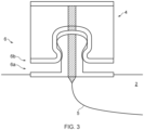
- Figure 3 schematically illustrates a cross sectional view of an example snap fastener acting as a connector 6.
- the snap fastener comprises a protrusion 6a and a groove 6b which is complementary to the protrusion.
- the connection is made by pressing the protrusion 6a into the lipped groove 6b such that the protrusion 6a fits within the groove and is held in place by the lip of the groove 6b.
- the protrusion 6a is present on the garment 2 and is connected to the electrical channel 5 present on the garment 2.
- the protrusion 6a comprises a conductive part which runs through its centre and connects a surface of the protrusion 6a to the electrical channel 5.
- the groove 6b is present on an underside of the contact pad 4 (or other component such as control circuit 3) and comprises a conductive part which connects the working parts of the contact pad 4 to an inner surface of the groove.
- a conductive part which connects the working parts of the contact pad 4 to an inner surface of the groove.
- the conductive parts of the groove and protrusion can be provided at the lips where contact is strongly maintained.
- the placement of the protrusion and groove can be reversed - i.e., the groove positioned at the garment 2 and the protrusion positioned at the contact pad 4.
- a similar concept can be applied to provide insulated electrical connectivity for Velcro or other hook-and-loop connections, for example by using conductive thread embedded in the centre of the hook-and-loop patches.
- two different kinds of connector 6 can be employed, with one kind configured to connect a first type of contact pad to the garment and another kind configured to connect a second type of contact pad to the garment, to encourage users to arrange the pads in a certain way.
- FIG. 4 schematically illustrates a wearable controller 10 comprising a first glove 12 and a second glove 22.
- Each glove comprises a number of contact pads 4 which are configured in a similar manner as those described with respect to Figures 1A and 1B .
- the first glove comprises a central controller circuit 3.
- Each of the contact pads 4, both on the first glove 12 and the second glove 22, are connected to the contact pads 4.
- the contact pads 4 can be directly connected in the manner described above.
- the contact pads 4 can also be connected to the central controller circuit 3, through wired connection.
- wireless communication is preferred across the two gloves.
- the contact pads on the second glove are in direct wireless communication with a communication unit on the central control circuit 3.
- the contact pads on the second glove can be connected to a communications unit on the second glove, which is configured to wirelessly send signals from the second glove to the control circuit 3 on the first glove.
- the contact pads on the second glove can be connected to each other and/or to the communications unit by conductive channels 5.
- the device can comprise an arm band as the first garment and a shirt as the second garment.
- any pad may still be arranged to generate an input independently based on pressure, either by use of a switch or a capacitive or resistive sensor or similar as described elsewhere herein. In this way the user can generate inputs by pressing such a pad on any surface, including other parts of the garment. In this case, optionally contact between two pads (or specifically a contact pad and an activation pad) may still be detected as a distinct input type.
- more generally 'contact pads' may refer to any type of pad herein, and include pads that operate independently, or in conjunction with another pad, or both.
- the wires may or may not be woven or otherwise integrated into the glove. If loose, then optionally the glove or other type of garment may comprise an inner layer and a removable outer layer; the pads may be configured on the inner layer, and then the loose wiring may be covered by replacing the outer layer of the garment.
Landscapes
- Engineering & Computer Science (AREA)
- Multimedia (AREA)
- Human Computer Interaction (AREA)
- General Engineering & Computer Science (AREA)
- Theoretical Computer Science (AREA)
- Physics & Mathematics (AREA)
- General Physics & Mathematics (AREA)
- Life Sciences & Earth Sciences (AREA)
- Health & Medical Sciences (AREA)
- Biophysics (AREA)
- Cardiology (AREA)
- General Health & Medical Sciences (AREA)
- Heart & Thoracic Surgery (AREA)
- Professional, Industrial, Or Sporting Protective Garments (AREA)
- User Interface Of Digital Computer (AREA)
- Outerwear In General, And Traditional Japanese Garments (AREA)
Claims (13)
- Tragbarer Steuerung (1), die Steuerung umfassend:ein Kleidungsstück (2);Kontaktpads (4, 4b, 4c, 4d, 4e) und ein oder mehrere Aktivierungspads (4a) zum Aktivieren der Kontaktpads, wobei die Kontaktpads und die Aktivierungspads über Verbinder (6) an dem Kleidungsstück lösbar befestigt sind, wobei ein bestimmter Verbinder einen Erkennungspunkt zum Erkennen, welches Kontaktpad oder Aktivierungspad über den bestimmten Verbinder an dem Kleidungsstück lösbar befestigt ist, umfasst; undeine programmierbare zentrale Steuerschaltung (3), wobeidie Kontaktpads und Aktivierungspads zu Signalzwecken mit der zentralen Steuerschaltung verbunden sind und die Kontaktpads betriebsfähig sind zum:Erzeugen von Eingangssignalen als Reaktion auf eine Benutzeraktion, derart, dass ein Eingangssignal nur dann erzeugt wird, wenn ein Kontaktpad mit einem Aktivierungspad in Kontakt kommt, undSenden der erzeugten Eingangssignale an die zentrale Steuerschaltung unddie zentrale Steuerschaltung betriebsfähig ist zum:Erkennen, über die innerhalb der Verbinder umfassten Erkennungspunkte, der Anordnung, in der Kontaktpads und Aktivierungspads an dem Kleidungsstück lösbar befestigt sind,Auswählen eines Profils basierend auf der erkannten Anordnung von Kontaktpads und Aktivierungspads, wobei das Profil angibt, welche Paare von Kontaktpads und Aktivierungspads eine Eingabe erzeugen, wenn sie miteinander in Kontakt kommen, undSenden der gemäß dem ausgewählten Profil erzeugten Eingangssignale an einen externen Prozessor eines Systems, das durch die tragbare Steuerung gesteuert werden soll.
- Tragbare Steuerung nach Anspruch 1, wobei die Verbinder auch eine elektrische Verbindung zwischen den Kontaktpads und der Steuerschaltung bereitstellen.
- Tragbare Steuerung nach einem der Ansprüche 1 und 2, wobei die Verbinder Klettverschlüsse aus Stoff umfassen.
- Tragbare Steuerung nach einem der vorstehenden Ansprüche, wobei die Verbinder einen Schnappverschluss umfassen.
- Tragbare Steuerung nach einem der vorstehenden Ansprüche, wobei die Kontaktpads leitfähiges Gewebe umfassen.
- Tragbare Steuerung nach einem der vorstehenden Ansprüche, wobei die Kontaktpads durch leitfähige Fäden mit der Steuerschaltung verbunden sind.
- Tragbare Steuerung nach einem der vorstehenden Ansprüche, wobei das Kleidungsstück ein Handschuh ist, umfassend einen Handflächenabschnitt und mindestens einen Fingerabschnitt, und die Steuerschaltung auf dem Handflächenabschnitt positioniert ist.
- Tragbare Steuerung nach einem der vorstehenden Ansprüche, wobei die Kontaktpads kapazitive Touchpads umfassen.
- Tragbare Steuerung nach einem der vorstehenden Ansprüche, wobei die Steuerschaltung über einen oder mehrere Verbinder an dem Kleidungsstück lösbar befestigt ist.
- Tragbare Steuerung nach einem der vorstehenden Ansprüche, ferner umfassend einen mit der zentralen Steuerschaltung verbundenen Beschleunigungsmesser zum Registrieren von Bewegung, Neigung und/oder Drehung der Steuerung.
- Tragbare Steuerung nach einem der vorstehenden Ansprüche, wobei das Kleidungsstück auf seiner Oberfläche mindestens einen leitfähigen Kanal umfasst, der konfiguriert ist, um bei Verwendung die zentrale Schaltung mit den leitfähigen Pads zu verbinden.
- Tragbare Steuerung nach Anspruch 11, wobei die leitfähigen Kanäle aus leitfähigem Faden gebildet sind, der in das Kleidungsstück eingebettet ist.
- Tragbare Steuerung nach einem der vorstehenden Ansprüche, ferner umfassend ein zweites Kleidungsstück;
ein oder mehrere sekundäre Kontaktpads, die über Verbinder an dem zweiten Kleidungsstück lösbar befestigt sind, wobei die sekundären Kontaktpads mit der zentralen Steuerschaltung verbunden sind und betriebsfähig sind, um als Reaktion auf eine Benutzeraktionen Eingangssignale zu erzeugen.
Applications Claiming Priority (1)
| Application Number | Priority Date | Filing Date | Title |
|---|---|---|---|
| GB2114267.4A GB2611533B (en) | 2021-10-05 | 2021-10-05 | Wearable controller |
Publications (2)
| Publication Number | Publication Date |
|---|---|
| EP4162992A1 EP4162992A1 (de) | 2023-04-12 |
| EP4162992B1 true EP4162992B1 (de) | 2025-06-04 |
Family
ID=78497946
Family Applications (1)
| Application Number | Title | Priority Date | Filing Date |
|---|---|---|---|
| EP22198366.1A Active EP4162992B1 (de) | 2021-10-05 | 2022-09-28 | Tragbare steuerung |
Country Status (3)
| Country | Link |
|---|---|
| US (1) | US12599835B2 (de) |
| EP (1) | EP4162992B1 (de) |
| GB (1) | GB2611533B (de) |
Family Cites Families (11)
| Publication number | Priority date | Publication date | Assignee | Title |
|---|---|---|---|---|
| US6141643A (en) * | 1998-11-25 | 2000-10-31 | Harmon; Steve | Data input glove having conductive finger pads and thumb pad, and uses therefor |
| US8241126B2 (en) | 2009-11-04 | 2012-08-14 | Valve Corporation | Video game controller having user swappable control components |
| US9282893B2 (en) | 2012-09-11 | 2016-03-15 | L.I.F.E. Corporation S.A. | Wearable communication platform |
| US9566512B2 (en) * | 2014-02-18 | 2017-02-14 | Lenovo (Singapore) Pte. Ltd. | Selectively arrangeable, multi-mode input controller |
| US10019059B2 (en) * | 2014-08-22 | 2018-07-10 | Sony Interactive Entertainment Inc. | Glove interface object |
| US10437345B2 (en) * | 2017-06-30 | 2019-10-08 | The Boeing Company | Modular fingertip sensors |
| KR102017299B1 (ko) * | 2017-09-27 | 2019-10-21 | 주식회사 모인 | Vr 글러브 |
| EP3909558A4 (de) * | 2019-02-08 | 2022-11-23 | NEOFECT Co., Ltd. | Trainingsvorrichtung zur handrehabilitation |
| EP3660633A1 (de) * | 2019-07-31 | 2020-06-03 | Taurum Technologies SL | Handgetragene dateneingabevorrichtung |
| US11681369B2 (en) * | 2019-09-16 | 2023-06-20 | Iron Will Innovations Canada Inc. | Control-point activation condition detection for generating corresponding control signals |
| US11360564B1 (en) * | 2021-05-13 | 2022-06-14 | Facebook Technologies, Llc | Tunable flexible haptic actuators and related devices, systems, and methods |
-
2021
- 2021-10-05 GB GB2114267.4A patent/GB2611533B/en active Active
-
2022
- 2022-09-28 EP EP22198366.1A patent/EP4162992B1/de active Active
- 2022-09-28 US US17/954,590 patent/US12599835B2/en active Active
Also Published As
| Publication number | Publication date |
|---|---|
| GB2611533B (en) | 2024-02-28 |
| GB2611533A (en) | 2023-04-12 |
| EP4162992A1 (de) | 2023-04-12 |
| GB202114267D0 (en) | 2021-11-17 |
| US12599835B2 (en) | 2026-04-14 |
| US20230110139A1 (en) | 2023-04-13 |
Similar Documents
| Publication | Publication Date | Title |
|---|---|---|
| JP5818386B2 (ja) | 指先部が導電性の手袋 | |
| JP7378456B2 (ja) | 取り外し可能なモジュールを有する着用可能な物品 | |
| US9003567B2 (en) | Hand covering with tactility features | |
| US8681101B1 (en) | Finger mounted input device | |
| US20080259028A1 (en) | Hand glove mouse | |
| CN201345897Y (zh) | 保持与操作电子设备的服饰物品 | |
| US8336119B2 (en) | Hand covering with conductive portion | |
| US20060280322A1 (en) | Discreet interface system | |
| WO2010097692A1 (en) | Touch sensitive wearable band apparatus and method | |
| WO2009033361A1 (fr) | Étoffe comprenant des zones sensibles détachables | |
| US20150077347A1 (en) | Ergonomically optimized remote controller device and method of use thereof | |
| CN102791191A (zh) | 手可佩戴控制设备 | |
| EP4162992B1 (de) | Tragbare steuerung | |
| US11357274B2 (en) | Glove | |
| KR102834490B1 (ko) | 회전 휠키를 구비한 스마트 링 | |
| KR20120023303A (ko) | 정전식 감응기구 조작이 가능한 장갑 | |
| JP3159402U (ja) | 手袋機能付き袖口構造 | |
| WO2007138292A2 (en) | Control gloves and control systems | |
| US12256789B2 (en) | Tactile stimulus providing apparatus | |
| CN209400980U (zh) | 一种空中鼠标 | |
| US20220334653A1 (en) | Controller Device And Method Of Use | |
| CN215232063U (zh) | 一种游戏手柄及游戏机 | |
| JP3180443U (ja) | 手袋 | |
| KR20190055647A (ko) | 원격제어 장치를 내장한 플렉서블 패치 | |
| WO2014058991A2 (en) | Conductive glove with conductive lining and conductive waterproof bladder |
Legal Events
| Date | Code | Title | Description |
|---|---|---|---|
| PUAI | Public reference made under article 153(3) epc to a published international application that has entered the european phase |
Free format text: ORIGINAL CODE: 0009012 |
|
| STAA | Information on the status of an ep patent application or granted ep patent |
Free format text: STATUS: REQUEST FOR EXAMINATION WAS MADE |
|
| 17P | Request for examination filed |
Effective date: 20221014 |
|
| AK | Designated contracting states |
Kind code of ref document: A1 Designated state(s): AL AT BE BG CH CY CZ DE DK EE ES FI FR GB GR HR HU IE IS IT LI LT LU LV MC MK MT NL NO PL PT RO RS SE SI SK SM TR |
|
| GRAP | Despatch of communication of intention to grant a patent |
Free format text: ORIGINAL CODE: EPIDOSNIGR1 |
|
| STAA | Information on the status of an ep patent application or granted ep patent |
Free format text: STATUS: GRANT OF PATENT IS INTENDED |
|
| RIC1 | Information provided on ipc code assigned before grant |
Ipc: A63F 13/218 20140101ALN20241220BHEP Ipc: A63F 13/214 20140101ALN20241220BHEP Ipc: G06F 3/01 20060101ALI20241220BHEP Ipc: A63F 13/211 20140101ALI20241220BHEP Ipc: A63F 13/428 20140101ALI20241220BHEP Ipc: A63F 13/24 20140101ALI20241220BHEP Ipc: A63F 13/22 20140101ALI20241220BHEP Ipc: A63F 13/212 20140101AFI20241220BHEP |
|
| INTG | Intention to grant announced |
Effective date: 20250108 |
|
| P01 | Opt-out of the competence of the unified patent court (upc) registered |
Free format text: CASE NUMBER: APP_7187/2025 Effective date: 20250212 |
|
| RIN1 | Information on inventor provided before grant (corrected) |
Inventor name: QUIROS, ESTEFANIA RODRIGUEZ |
|
| GRAS | Grant fee paid |
Free format text: ORIGINAL CODE: EPIDOSNIGR3 |
|
| GRAA | (expected) grant |
Free format text: ORIGINAL CODE: 0009210 |
|
| STAA | Information on the status of an ep patent application or granted ep patent |
Free format text: STATUS: THE PATENT HAS BEEN GRANTED |
|
| AK | Designated contracting states |
Kind code of ref document: B1 Designated state(s): AL AT BE BG CH CY CZ DE DK EE ES FI FR GB GR HR HU IE IS IT LI LT LU LV MC MK MT NL NO PL PT RO RS SE SI SK SM TR |
|
| REG | Reference to a national code |
Ref country code: GB Ref legal event code: FG4D |
|
| REG | Reference to a national code |
Ref country code: CH Ref legal event code: EP |
|
| REG | Reference to a national code |
Ref country code: DE Ref legal event code: R096 Ref document number: 602022015414 Country of ref document: DE |
|
| REG | Reference to a national code |
Ref country code: IE Ref legal event code: FG4D |
|
| REG | Reference to a national code |
Ref country code: NL Ref legal event code: FP |
|
| PGFP | Annual fee paid to national office [announced via postgrant information from national office to epo] |
Ref country code: NL Payment date: 20250820 Year of fee payment: 4 |
|
| PG25 | Lapsed in a contracting state [announced via postgrant information from national office to epo] |
Ref country code: FI Free format text: LAPSE BECAUSE OF FAILURE TO SUBMIT A TRANSLATION OF THE DESCRIPTION OR TO PAY THE FEE WITHIN THE PRESCRIBED TIME-LIMIT Effective date: 20250604 Ref country code: ES Free format text: LAPSE BECAUSE OF FAILURE TO SUBMIT A TRANSLATION OF THE DESCRIPTION OR TO PAY THE FEE WITHIN THE PRESCRIBED TIME-LIMIT Effective date: 20250604 |
|
| PGFP | Annual fee paid to national office [announced via postgrant information from national office to epo] |
Ref country code: DE Payment date: 20250820 Year of fee payment: 4 |
|
| REG | Reference to a national code |
Ref country code: LT Ref legal event code: MG9D |
|
| PG25 | Lapsed in a contracting state [announced via postgrant information from national office to epo] |
Ref country code: NO Free format text: LAPSE BECAUSE OF FAILURE TO SUBMIT A TRANSLATION OF THE DESCRIPTION OR TO PAY THE FEE WITHIN THE PRESCRIBED TIME-LIMIT Effective date: 20250904 Ref country code: GR Free format text: LAPSE BECAUSE OF FAILURE TO SUBMIT A TRANSLATION OF THE DESCRIPTION OR TO PAY THE FEE WITHIN THE PRESCRIBED TIME-LIMIT Effective date: 20250905 |
|
| PG25 | Lapsed in a contracting state [announced via postgrant information from national office to epo] |
Ref country code: PL Free format text: LAPSE BECAUSE OF FAILURE TO SUBMIT A TRANSLATION OF THE DESCRIPTION OR TO PAY THE FEE WITHIN THE PRESCRIBED TIME-LIMIT Effective date: 20250604 |
|
| PG25 | Lapsed in a contracting state [announced via postgrant information from national office to epo] |
Ref country code: BG Free format text: LAPSE BECAUSE OF FAILURE TO SUBMIT A TRANSLATION OF THE DESCRIPTION OR TO PAY THE FEE WITHIN THE PRESCRIBED TIME-LIMIT Effective date: 20250604 |
|
| PG25 | Lapsed in a contracting state [announced via postgrant information from national office to epo] |
Ref country code: HR Free format text: LAPSE BECAUSE OF FAILURE TO SUBMIT A TRANSLATION OF THE DESCRIPTION OR TO PAY THE FEE WITHIN THE PRESCRIBED TIME-LIMIT Effective date: 20250604 |
|
| PGFP | Annual fee paid to national office [announced via postgrant information from national office to epo] |
Ref country code: AT Payment date: 20251020 Year of fee payment: 4 Ref country code: FR Payment date: 20250820 Year of fee payment: 4 |
|
| PG25 | Lapsed in a contracting state [announced via postgrant information from national office to epo] |
Ref country code: RS Free format text: LAPSE BECAUSE OF FAILURE TO SUBMIT A TRANSLATION OF THE DESCRIPTION OR TO PAY THE FEE WITHIN THE PRESCRIBED TIME-LIMIT Effective date: 20250904 |
|
| PG25 | Lapsed in a contracting state [announced via postgrant information from national office to epo] |
Ref country code: LV Free format text: LAPSE BECAUSE OF FAILURE TO SUBMIT A TRANSLATION OF THE DESCRIPTION OR TO PAY THE FEE WITHIN THE PRESCRIBED TIME-LIMIT Effective date: 20250604 |
|
| PG25 | Lapsed in a contracting state [announced via postgrant information from national office to epo] |
Ref country code: PT Free format text: LAPSE BECAUSE OF FAILURE TO SUBMIT A TRANSLATION OF THE DESCRIPTION OR TO PAY THE FEE WITHIN THE PRESCRIBED TIME-LIMIT Effective date: 20251006 |
|
| REG | Reference to a national code |
Ref country code: AT Ref legal event code: MK05 Ref document number: 1799836 Country of ref document: AT Kind code of ref document: T Effective date: 20250604 |
|
| PG25 | Lapsed in a contracting state [announced via postgrant information from national office to epo] |
Ref country code: IS Free format text: LAPSE BECAUSE OF FAILURE TO SUBMIT A TRANSLATION OF THE DESCRIPTION OR TO PAY THE FEE WITHIN THE PRESCRIBED TIME-LIMIT Effective date: 20251004 |
|
| PG25 | Lapsed in a contracting state [announced via postgrant information from national office to epo] |
Ref country code: AT Free format text: LAPSE BECAUSE OF FAILURE TO SUBMIT A TRANSLATION OF THE DESCRIPTION OR TO PAY THE FEE WITHIN THE PRESCRIBED TIME-LIMIT Effective date: 20250604 Ref country code: SM Free format text: LAPSE BECAUSE OF FAILURE TO SUBMIT A TRANSLATION OF THE DESCRIPTION OR TO PAY THE FEE WITHIN THE PRESCRIBED TIME-LIMIT Effective date: 20250604 |
|
| PG25 | Lapsed in a contracting state [announced via postgrant information from national office to epo] |
Ref country code: CZ Free format text: LAPSE BECAUSE OF FAILURE TO SUBMIT A TRANSLATION OF THE DESCRIPTION OR TO PAY THE FEE WITHIN THE PRESCRIBED TIME-LIMIT Effective date: 20250604 |
|
| PG25 | Lapsed in a contracting state [announced via postgrant information from national office to epo] |
Ref country code: EE Free format text: LAPSE BECAUSE OF FAILURE TO SUBMIT A TRANSLATION OF THE DESCRIPTION OR TO PAY THE FEE WITHIN THE PRESCRIBED TIME-LIMIT Effective date: 20250604 |
|
| PG25 | Lapsed in a contracting state [announced via postgrant information from national office to epo] |
Ref country code: SK Free format text: LAPSE BECAUSE OF FAILURE TO SUBMIT A TRANSLATION OF THE DESCRIPTION OR TO PAY THE FEE WITHIN THE PRESCRIBED TIME-LIMIT Effective date: 20250604 |
|
| PG25 | Lapsed in a contracting state [announced via postgrant information from national office to epo] |
Ref country code: IT Free format text: LAPSE BECAUSE OF FAILURE TO SUBMIT A TRANSLATION OF THE DESCRIPTION OR TO PAY THE FEE WITHIN THE PRESCRIBED TIME-LIMIT Effective date: 20250604 |
|
| PG25 | Lapsed in a contracting state [announced via postgrant information from national office to epo] |
Ref country code: RO Free format text: LAPSE BECAUSE OF FAILURE TO SUBMIT A TRANSLATION OF THE DESCRIPTION OR TO PAY THE FEE WITHIN THE PRESCRIBED TIME-LIMIT Effective date: 20250604 |
|
| REG | Reference to a national code |
Ref country code: DE Ref legal event code: R097 Ref document number: 602022015414 Country of ref document: DE |
|
| PLBE | No opposition filed within time limit |
Free format text: ORIGINAL CODE: 0009261 |
|
| STAA | Information on the status of an ep patent application or granted ep patent |
Free format text: STATUS: NO OPPOSITION FILED WITHIN TIME LIMIT |
|
| PG25 | Lapsed in a contracting state [announced via postgrant information from national office to epo] |
Ref country code: DK Free format text: LAPSE BECAUSE OF FAILURE TO SUBMIT A TRANSLATION OF THE DESCRIPTION OR TO PAY THE FEE WITHIN THE PRESCRIBED TIME-LIMIT Effective date: 20250604 |
|
| REG | Reference to a national code |
Ref country code: CH Ref legal event code: L10 Free format text: ST27 STATUS EVENT CODE: U-0-0-L10-L00 (AS PROVIDED BY THE NATIONAL OFFICE) Effective date: 20260416 |