EP4163004A1 - Vorrichtung zur abtrennung eines stoffes aus einem gas - Google Patents
Vorrichtung zur abtrennung eines stoffes aus einem gas Download PDFInfo
- Publication number
- EP4163004A1 EP4163004A1 EP22197588.1A EP22197588A EP4163004A1 EP 4163004 A1 EP4163004 A1 EP 4163004A1 EP 22197588 A EP22197588 A EP 22197588A EP 4163004 A1 EP4163004 A1 EP 4163004A1
- Authority
- EP
- European Patent Office
- Prior art keywords
- filter
- module
- frame
- modules
- housing
- Prior art date
- Legal status (The legal status is an assumption and is not a legal conclusion. Google has not performed a legal analysis and makes no representation as to the accuracy of the status listed.)
- Granted
Links
Images


Classifications
-
- B—PERFORMING OPERATIONS; TRANSPORTING
- B01—PHYSICAL OR CHEMICAL PROCESSES OR APPARATUS IN GENERAL
- B01D—SEPARATION
- B01D46/00—Filters or filtering processes specially modified for separating dispersed particles from gases or vapours
- B01D46/02—Particle separators, e.g. dust precipitators, having hollow filters made of flexible material
-
- B—PERFORMING OPERATIONS; TRANSPORTING
- B01—PHYSICAL OR CHEMICAL PROCESSES OR APPARATUS IN GENERAL
- B01D—SEPARATION
- B01D46/00—Filters or filtering processes specially modified for separating dispersed particles from gases or vapours
- B01D46/10—Particle separators, e.g. dust precipitators, using filter plates, sheets or pads having plane surfaces
- B01D46/12—Particle separators, e.g. dust precipitators, using filter plates, sheets or pads having plane surfaces in multiple arrangements
-
- B—PERFORMING OPERATIONS; TRANSPORTING
- B01—PHYSICAL OR CHEMICAL PROCESSES OR APPARATUS IN GENERAL
- B01D—SEPARATION
- B01D25/00—Filters formed by clamping together several filtering elements or parts of such elements
- B01D25/02—Filters formed by clamping together several filtering elements or parts of such elements in which the elements are pre-formed independent filtering units, e.g. modular systems
-
- B—PERFORMING OPERATIONS; TRANSPORTING
- B01—PHYSICAL OR CHEMICAL PROCESSES OR APPARATUS IN GENERAL
- B01D—SEPARATION
- B01D27/00—Cartridge filters of the throw-away type
-
- B—PERFORMING OPERATIONS; TRANSPORTING
- B01—PHYSICAL OR CHEMICAL PROCESSES OR APPARATUS IN GENERAL
- B01D—SEPARATION
- B01D27/00—Cartridge filters of the throw-away type
- B01D27/08—Construction of the casing
-
- B—PERFORMING OPERATIONS; TRANSPORTING
- B01—PHYSICAL OR CHEMICAL PROCESSES OR APPARATUS IN GENERAL
- B01D—SEPARATION
- B01D46/00—Filters or filtering processes specially modified for separating dispersed particles from gases or vapours
- B01D46/0002—Casings; Housings; Frame constructions
- B01D46/0013—Modules
-
- B—PERFORMING OPERATIONS; TRANSPORTING
- B01—PHYSICAL OR CHEMICAL PROCESSES OR APPARATUS IN GENERAL
- B01D—SEPARATION
- B01D46/00—Filters or filtering processes specially modified for separating dispersed particles from gases or vapours
- B01D46/56—Filters or filtering processes specially modified for separating dispersed particles from gases or vapours with multiple filtering elements, characterised by their mutual disposition
- B01D46/62—Filters or filtering processes specially modified for separating dispersed particles from gases or vapours with multiple filtering elements, characterised by their mutual disposition connected in series
- B01D46/64—Filters or filtering processes specially modified for separating dispersed particles from gases or vapours with multiple filtering elements, characterised by their mutual disposition connected in series arranged concentrically or coaxially
Definitions
- the invention relates to a device for separating a substance from a gas, comprising a housing and at least one filter module, the filter module having at least one filter element which is held in a frame.
- Devices for separating solids from a gas stream are widely used in the art and have been described many times.
- modular systems are also known. That's how she describes it DE 196 45 096 A1 an air cleaning device with an intake part, a fan housing with one or more fans and one or more air filters arranged before or after the fan.
- the device has a housing designed with a base and made up of tower-like functional parts arranged one above the other, interlocking in the sealing seat and easily detachable from one another, modularly designed functional parts, which are clamped together with at least one pivoting lever arranged on the lateral part of the housing by means of a pivoting receptacle.
- the swiveling lever encompasses all parts of the housing from the outside.
- the object of the present invention is to simplify the construction of such filter devices.
- the object of the invention is achieved with the device mentioned at the outset in that the frame of the filter module forms part of the housing, with the filter element not being detachably connected to this frame.
- the filter module of the invention forms an independent unit that can also be used in the most varied of filter configurations of such an air filter system quickly and without having to take any further adjustment measures.
- the modularity of a device for separating a substance from a gas is thus further expanded with the invention.
- the improved modularity allows the device to be constructed more simply, since an outer housing, which is currently standard, for accommodating the filter elements is no longer required.
- disposal is also easier to carry out, since the filter module can be disposed of as a whole and does not have to be removed from a separate housing and packed in a complex manner.
- the frame itself may already form part of the packaging for disposal.
- the frame consists of a non-metallic material, with which the disposal of the used filter module can be simplified, in particular if the filter element also consists of a non-metallic material.
- the frame consists at least partially of a fiber material, with which the above-mentioned effect can be further improved.
- the frame of the filter module can also be given greater strength, in particular if wood fibers are used as the material.
- each of the filter modules being designed with a filter element that is held by a frame, and with all the frames of the filter modules forming part of the housing of the device. It is thus possible to enable the most varied combinations of filter modules in such devices, for example with regard to the filter class, i.e. the particle retention capacity of the filter elements.
- a (simultaneous) separation of gases can also take place with appropriate filter particles, such as activated carbon.
- a sealing element is formed on the filter module.
- the sealing connection between the individual housing components can also be improved in this way.
- the several filter modules are connected to one another via clamping locks. It is thus possible to assemble the device quickly without tools or to disassemble it quickly without tools.
- one of the filter modules is connected to a connection module that has an inlet for a gas to be cleaned and/or that this has a suction module, wherein the suction module is connected to the connection module exclusively via the filter module or the filter modules.
- the device can also be given a poka-yoke functionality that specifies a specific assembly sequence for the user of the device, for example with regard to the sequence of filter elements of different filter classes.
- a handling element for example a belt or the like, to be arranged on the at least one filter module.
- At least one flow channel is arranged in at least one frame wall, which has a flow connection to a space surrounded by the frame, or that at least two flow channels are arranged in the frame for each filter module, with a Flow channel is flow-connected to a first measuring point below the filter element and the second flow channel is flow-connected to a second measuring point above the filter element.
- a preferred embodiment variant of a device 1 for separating a substance from a gas (hereinafter referred to simply as device 1) is shown.
- the device 1 can also be referred to as an air filter.
- the device 1 can be used, for example, to separate solids from the exhaust air from welding systems (so-called welding fumes), from soldering systems, from flame and plasma cutting systems, from laser systems, from grinding dust, for cleaning oil and emulsion mist, paint mist, etc.
- the particles can be separated into different fractions, for example as coarse dust and fine dust.
- These applications of the device 1 are to be understood as examples and are not to be understood as limiting the range of applications of the device 1 .
- the device 1 can also be used to separate a gas from a gas stream.
- the device 1 after 1 comprises a suction module 2, a connection module 3 and two filter modules 4, 5 or consists of them.
- one of two different numbers of filter modules 4, 5 can be provided in the device 1, for example only one or three or four or five, etc.
- the suction module 2, the at least one filter module 4 or the filter modules 4, 5 and the connection module 3 are arranged one above the other, with the at least one filter module 4 or the filter modules 4, 5 being arranged between the suction module 2 and the connection module 3.
- the intake module 2 is connected to the connection module 3 exclusively via the filter module 4 or the plurality of filter modules 4, 5, so that there is no further connecting element between them.
- a connecting element such as a connecting bracket or at least one screw connection, etc., in addition or as an alternative to the connection via the filter module(s) 4, 5.
- the modules of the device 1 are arranged one above the other like a tower.
- the suction module 2 is preferably the lowest module of the device 1, but can optionally also be arranged at a different point in the device 1, for example at the very top.
- Suction module 2 hides the technology of device 1, i.e. for example at least one suction device, such as a fan, a control and/or regulating device, etc. Since these technical components are known from such air filter systems or devices 1, please refer to further details referred to the relevant state of the art.
- connection module 3 preferably forms the upper end of the device 1, but can also be arranged at a different point in the device 1.
- the connection module 3 has at least one inlet 6 .
- the contaminated gas for example the contaminated air
- the inlet 6 can be provided for the connection of a line for the contaminated gas or an extraction device, for example an extraction hood.
- the inlet 6 is arranged on the side of the connection module 3. But it can also be arranged at the top.
- the device 1 can also have more than one suction module 2 and/or more than one connection module 3 .
- the at least one inlet 6 of the connection module housing 8 are oriented or formed accordingly.
- the inlet 6 can be formed by a tube that is open at the bottom.
- the suction module 2 has a suction module housing 7 and the connection module 3 has a connection module housing 8 .
- the intake module housing 7 and the connection module housing 8 can be made of metal, for example, in particular sheet metal.
- the suction module housing 7 and the connection module housing 8 are part of a housing 9 of the device 1, which forms the outer shell of the device 1.
- the filter module 4 is shown.
- the filter modules 4, 5 of a device 1 can be of the same design in principle, so that only one filter module 4 is described below.
- the filter module 4 has at least one filter element 10 . More than one filter element 10 can also be arranged in the filter module 4, for example two directly one above the other or at a distance from one another.
- filter element 10 there is more than one filter element 10 per filter module 4, these can be of the same or different design. In particular, they can have a different permeability for solid particles, ie have a different filter class.
- filter modules 4, 5 are arranged in the device, then these can (exclusively) differ in filter elements 10 that belong to different filter classes, so that, for example, coarse and fine dust separation with the device 1 is possible.
- the structural design of the filter modules can be the same or possibly also different, for example by the filter modules 4, 5 having different heights.
- the at least one filter element 10 is held in a frame 11 of the filter module 4 and is not detachably (inseparably) connected to it.
- non-detachable means that the filter element 10 cannot be separated from the frame without destroying the filter element 10 and/or the connecting means, as is the case with detachable connections.
- the filter element 10 can be cohesively connected to the frame 11 be, for example glued or welded, for example by means of a thermoplastic material.
- other connection methods can also be used, for example the filter element 10 can be riveted or sewn onto the frame 11, etc.
- the filter element 10 can be arranged adjacent to or resting on a web 12 or can be arranged engaging in a groove of this web 12 .
- the web 12 or corresponding parts thereof is/are preferably formed in one piece with the frame 11 or frame walls 13 .
- the frame 11 may be formed from a single frame wall 13, the opposite faces of which are joined together to form the frame 11 (i.e. a shell).
- the frame 11 can also be formed from a plurality of frame walls 13 which are connected to one another, for example materially, e.g. glued, and/or form-fitting and/or force-fitting, e.g. by screws or rivets.
- the frame 11 defines an open area surrounded by the frame 11 .
- the filter element 10 occupies this free area entirely, so that the gas to be cleaned must necessarily flow through the filter element 10 .
- the filter element 10 is preferably planar, for example in the form of a plate. It can consist of a filter fabric or a paper filter or another filter material known for the purposes mentioned, such as activated carbon (for gases) and optionally have a support structure if the inherent rigidity is not sufficient.
- the filter element 10 can, for example, have an area of between 5 m 2 and 40 m 2 . However, this information is not to be understood as limiting.
- the frame 11 forms part of the housing 9, so that the filter module 4 is not used in an additional housing.
- the housing of the device 1 according to Fig.1 formed from the suction module housing 7, the connection module housing 8 and the at least one frame 11 of the at least one filter module 4, 5.
- the frame 11 can have a height 14 suitable for the function of the filter module 4 .
- the height 14 can be, for example, between 10 cm and 60 cm, in particular between 10 cm and 40 cm. “Appropriately” means that the filter module 4 should also have sufficient volume to accommodate substances separated from the gas.
- the frame 11 can therefore be designed, for example, in the form of a shell of a cuboid or generally in the form of a shell. In the context of the invention, the term "frame 11" is therefore not necessarily to be understood in such a way that it is formed relatively flat in the manner of a picture frame and is composed of strips.
- the frame 11 can consist of a metallic material. In the preferred embodiment, however, the frame consists partially or entirely of a non-metallic material.
- a fiber material is particularly preferably used, such as a wood fiber material, e.g. MDF boards, or materials made of cellulose or ground wood or waste paper, such as in particular cardboard or corrugated cardboard.
- thermoplastic or duroplastic plastics can also be used, for example in the form of plastic sheets or multi-wall sheets, etc.
- An end face 15 of the frame 11 can be designed or provided with at least one form-fitting element, for example stepped, groove-shaped, with a web, etc..
- the two axial end faces 15 of the frame 11 can each have complementary form-fitting elements, so that a form-fitting connection is formed between a plurality of filter modules 4, 5 placed one on top of the other.
- the filter modules 4, 5 of a device 1 preferably have the same cross-sectional shape and cross-sectional size, so that the device 1 is preferably cuboid.
- some or all of these modules can be positively connected to one another.
- the clamping closures 16 per se can correspond to the state of the art for this purpose be trained. As is known, when they are closed, they exert a tensile force which causes the parts connected thereto to be tightened.
- the toggle fasteners 16 may include a hook member and a shackle member, with the shackle member being hooked onto the hook member for closure and being closed with a pivoting motion.
- the bracket element and the hook element are each attached to different modules of the housing 9 of the device 1 .
- the clamping closures 16 can optionally have a security element against unintentional opening.
- the non-positive connection between the modules of the housing 9 of the device 1 can also be made differently, for example by screws, toggle levers, using an eccentric connector consisting of a rotatable eccentric in which the head of a bolt is accommodated, the eccentric in a first module and the bolt are arranged in a second module directly adjoining the first module (as is known for the connection of furniture carcass panels), etc.
- the individual modules of the device 1 are connected to one another in a sealed manner, so that no gas flow escapes between the modules when the device 1 is in operation.
- a sealing element in particular an elastomer seal, can be arranged between the modules.
- the sealing element 17 can also be integrally formed on the frame 11 of the filter module 4, preferably on one of the end faces 15. Both end faces 15 can also be provided with an integrally formed sealing element 17.
- the sealing element 17 can, for example, also be partially accommodated in a groove of the end face 15 .
- the molding itself can take place, for example, by means of injection molding or by spraying onto the frame 11, etc.
- the handling element 18 can be a handle or a loop or a band, etc. It is also possible for the handling element 18 to be formed in the frame 11 itself, for example as a recessed grip. The latter can optionally also be used as a counterpart for a clamping closure 16, particularly if the recessed grip is executed undercut.
- the loop or the band can be attached to the outside and/or inside of the respective module.
- a cover element can be provided.
- the cover element can be placed, for example, on the end face 15 of the frame 11 , possibly covering the frame 11 .
- a slot can also be provided in a frame wall 13, into which the cover element is pushed before the removal of the filter module 4 from the device 1, and the filter element 10 is thus covered. This slot can be provided with a destructible cover, e.g.
- a seal can be arranged between the cover element and the frame 11 in order to achieve a tight closure of the filter module 4.
- the seal can be formed by the sealing element 17 mentioned above.
- the seal can also be placed separately or connected to the cover element, for example glued or molded on.
- cover element can be connected to the frame 11, for example via one of the above-mentioned positive and/or non-positive connection elements for connecting the modules of the device 1 to one another, such as the clamping lock 16, etc.
- a hose 20 is also shown.
- This hose 20 is arranged on the frame 11 and has at least one flow connection in the space 21 (volume) of the filter module 4 surrounded by the frame 11. It is thus possible to measure the differential pressure of the filter resistance.
- the degree of contamination of the filter element 10 can be inferred from the filter resistance. The higher the resistance is compared with the value of a filter element 10 of the same filter class, the more material filtered from the gas is in/on the filter element 10.
- the hose 20 is connected to a pressure measuring device, not shown in any more detail, in particular a differential pressure sensor.
- Two measuring points 22, 23 are to be provided for the differential pressure measurement.
- Each of the measuring points 22, 23 has a hose 20.
- At least two hoses 20 or measuring points 22, 23 are therefore preferably arranged per filter module 4, 5, as can be seen in FIGS Figures 2 and 3 is evident.
- the measuring point 22 and thus a hose 20 is arranged below the filter element 10 and the measuring point 23 and thus a hose 20 is arranged above the filter element 10 .
- the hose 20 or hoses 20 can be arranged in a protective tube. Instead of the hoses 20 or in flow connection with them, other line elements, such as pipes, etc., can also be arranged.
- At least one flow channel 24 is arranged within at least one of the frame walls 13 .
- two such flow channels 24 per filter module 4, 5 are provided.
- the flow channel 24 extends or the flow channels 24 preferably extend in the vertical direction.
- the flow channel 24 or the flow channels 24 has a flow connection 25 into the space 21 of the filter module 4, the flow channels 24 each having separate flow connections 25 and the flow channels 24 not being connected to one another in order to obtain the correct value at the respective measuring point 22, 23 to capture.
- the flow channel 24 or the flow channels 24 and/or the flow connections 25 can be introduced into the filter module 4 or the filter modules 4, 5 in the form of bores. However, it or they can also already have been correspondingly formed during the production of the filter module 4 or the filter modules 4, 5.
- the flow channel 24 or the flow channels 24 and/or the flow connections 25 can have a round or a square or generally polygonal cross section.
- the flow channel 24 or the flow channels 24 extend over the entire height of a filter module 4, at least one of the two exit points in the frame 11, for example the upper one, can be closed with a sealing element 26.
- the sealing element can be formed, for example, by the sealing element 17 or the elastomer seal, with which the filter modules 4, 5 can be arranged in a sealing manner against one another, as was explained above.
- At least one of the flow channels 24 in the frame wall of a filter module 4 can be flow-connected to a flow channel 24 in the (same) frame wall 13 .
- the flow connection of the flow channels 24 can be formed automatically when the filter modules 4, 5 are arranged one on top of the other, so that a continuous flow channel 24 through a plurality of filter modules 4, 5 is formed.
- the sealing element 26 can accordingly be arranged differently or provided with a recess in order to allow this flow connection.
- a flow connection can be established between the filter modules 4, 5 (in particular between immediately adjacent filter modules 4, 5) via a further flow connection element (e.g. a hose).
- a further flow connection element e.g. a hose
- the exemplary embodiments show or describe possible embodiment variants of the device 1 for separating a (solid) substance from a gas, it being noted at this point that combinations of the individual embodiment variants with one another are also possible.
Landscapes
- Chemical & Material Sciences (AREA)
- Chemical Kinetics & Catalysis (AREA)
- Filtering Of Dispersed Particles In Gases (AREA)
Abstract
Description
- Die Erfindung betrifft eine Vorrichtung zur Abtrennung eines Stoffes aus einem Gas, umfassend ein Gehäuse und zumindest ein Filtermodul, wobei das Filtermodul zumindest ein Filterelement aufweist, das in einem Rahmen gehalten ist.
- Vorrichtungen zur Abscheidung von Feststoffen aus einem Gasstrom sind der der Technik weit verbreitet und oftmals beschrieben worden. Unter anderem sind auch modular aufgebaute Systeme bekannt. So beschreibt die
DE 196 45 096 A1 ein Luftreinigungsgerät mit einem Ansaugteil, einem Ventilatorgehäuse mit einem oder mehreren Ventilatoren und ein oder mehrere, vor oder nach dem Ventilator angeordnete, Luftfilter. Das Gerät weist ein mit einem Sockel ausgebildetes Gehäuse aus turmartig übereinander angeordneten, im Dichtsitz ineinandergreifenden und voneinander leicht lösbaren, modulartig ausgebildeten Funktionsteilen auf, die mit mindestens einem, am seitlichen Teil des Gehäuses mittels einer Schwenkaufnahme schwenkbar angeordneten Schwenkhebel zusammengespannt sind. Der Schwenkhebel umgreift dabei alle Teile des Gehäuses von außen. - Der vorliegenden Erfindung liegt die Aufgabe zu Grunde, den Aufbau derartiger Filtervorrichtungen zu vereinfachen.
- Die Aufgabe der Erfindung wird bei eingangs genannter Vorrichtung dadurch gelöst, dass der Rahmen des Filtermoduls einen Teil des Gehäuses bildet, wobei das Filterelement mit diesem Rahmen nicht lösbar verbunden ist.
- Von Vorteil ist dabei, dass es damit nicht mehr notwendig ist, das Filter an sich in ein gesondertes Gehäuse einzusetzen. Vielmehr bildet das Filtermodul der Erfindung eine eigenständige Einheit, die auch in unterschiedlichsten Filterkonfigurationen einer derartigen Luftfilteranlage rasch, und ohne weitere Anpassungsmaßnahmen treffen zu müssen, eingesetzt werden kann. Somit wird mit der Erfindung die Modularität einer Vorrichtung zur Abtrennung eines Stoffes aus einem Gas weiter ausgebaut. Die verbesserte Modularität erlaubt einen vereinfachen Aufbau der Vorrichtung, da ein derzeit übliches Übergehäuse zur Aufnahme der Filterelemente nicht mehr erforderlich ist. Neben diesem vereinfachten Aufbau ist aber auch die Entsorgung einfacher durchführbar, da das Filtermodul als gesamtes entsorgt werden kann und nicht aus einem gesonderten Gehäuse herausgenommen und aufwändig verpackt werden muss. Der Rahmen selbst kann bereits einen Teil der Verpackung für die Entsorgung bilden.
- Gemäß einer bevorzugten Ausführungsvariante der Erfindung kann vorgesehen sein, dass der Rahmen aus einem nichtmetallischen Werkstoff besteht, womit die Entsorgung des gebrauchten Filtermoduls vereinfacht werden kann, insbesondere wenn das Filterelement ebenfalls aus einem nichtmetallischen Werkstoff besteht.
- Nach einer Ausführungsvariante dazu kann vorgesehen sein, dass der Rahmen zumindest teilweise aus einem Faserwerkstoff besteht, womit der voranstehend genannte Effekt weiter verbessert werden kann. Zudem kann damit dem Rahmen des Filtermoduls auch eine höhere Festigkeit verliehen werden, insbesondere wenn Holzfasern als Werkstoff eingesetzt werden.
- Zu weiteren Erhöhung der Modularität kann entsprechend einer anderen Ausführungsvariante der Erfindung vorgesehen sein, dass mehrere Filtermodule übereinander angeordnet sind, wobei jedes der Filtermodule mit einem Filterelement, das von einem Rahmen gehalten ist, ausgebildet ist, und wobei sämtliche Rahmen der Filtermodule einen Teil des Gehäuses der Vorrichtung bilden. Es ist damit möglich, unterschiedlichste Zusammenstellungen von Filtermodulen in derartigen Vorrichtungen zu ermöglichen, beispielsweise in Hinblick auf die Filterklasse, d.h. das Partikel-Rückhaltevermögen der Filterelemente. Zudem kann mit entsprechenden Filterpartikeln, wie beispielsweise Aktivkohle, auch eine (gleichzeitige) Abscheidung von Gasen erfolgen.
- Zur Verbesserung der Handhabung des Filtermoduls kann gemäß einer Ausführungsvariante der Erfindung vorgesehen sein, dass an dem Filtermodul ein Dichtelement angeformt ist. Zusätzlich kann damit auch die dichtende Verbindung zwischen den einzelnen Gehäusebestandteilen verbessert werden.
- Ebenfalls zur Vereinfachung der Handhabbarkeit der Filtermodule kann nach einer anderen Ausführungsvariante der Erfindung vorgesehen sein, dass die mehreren Filtermodule über Spann-Verschlüsse miteinander verbunden sind. Es ist damit ein rascher werkzeugloser Zusammenbau bzw. eine rasche werkzeuglose Demontage der Vorrichtung möglich.
- Gemäß weiteren Ausführungsvarianten kann zur weiteren Vereinfachung des Aufbaus der Vorrichtung zur Abtrennung eines Stoffes aus einem Gas vorgesehen werden, dass eines der Filtermodule mit einem Anschlussmodul verbunden ist, das einen Einlass für ein zu reinigendes Gas aufweist und/oder dass diese ein Saugmodul aufweist, wobei das Saugmodul ausschließlich über das Filtermodul oder die Filtermodule mit dem Anschlussmodul verbunden ist.
- Zur Verbesserung der Stabilität der Vorrichtung zur Abtrennung eines Stoffes aus einem Gas kann entsprechend einer Ausführungsvariante der Erfindung vorgesehen sein, dass zwischen Gehäuseteilen ein Formschluss ausgebildet ist. Bei entsprechender Gestaltung der Formschlüsse kann damit der Vorrichtung auch eine Poka Yoke Funktionalität verliehen werden, die dem Anwender der Vorrichtung eine bestimmte Abfolge des Zusammenbaus vorgibt, beispielsweise in Hinblick auf die Abfolge von Filterelementen unterschiedlicher Filterklassen.
- Zur Verbesserung der Handhabung der Filtermodule kann gemäß einer weiteren Ausführungsvariante der Erfindung vorgesehen sein, dass an dem zumindest einen Filtermodul ein Handhabungselement, beispielsweise ein Band oder dgl., angeordnet ist.
- Nach weiteren Ausführungsvarianten der Erfindung kann zur Feststellung der Filterverschmutzung vorgesehen sein, dass in zumindest einer Rahmenwand zumindest ein Strömungskanal angeordnet ist, der zu einem vom Rahmen umgebenen Raum eine Strömungsverbindung aufweist, bzw. dass pro Filtermodul zumindest zwei Strömungskanäle im Rahmen angeordnet sind, wobei ein Strömungskanal mit einer ersten Messstelle unterhalb des Filterelementes strömungsverbunden ist und der zweite Strömungskanal mit einer zweiten Messstelle oberhalb des Filterelementes strömungsverbunden ist. Durch die Anordnung des zumindest einen Strömungskanals innerhalb der Wand ist dieser besser vor einer Beschädigung geschützt.
- Zum besseren Verständnis der Erfindung wird diese anhand der nachfolgenden Figuren näher erläutert.
- Es zeigt jeweils in vereinfachter, schematischer Darstellung:
- Fig. 1
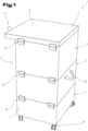
- Eine Vorrichtung zur Abtrennung eines Stoffes aus einem Gas;
- Fig. 2
- Ein Filtermodul;
- Fig. 3
- Einen Ausschnitt aus einer Ausführungsvariante eines Filtermoduls in Seitenansicht geschnitten;
- Fig. 4
- Einen Ausschnitt aus einer weiteren Ausführungsvariante eines Filtermoduls in Seitenansicht geschnitten;
- Fig. 5
- Einen Ausschnitt des Filtermoduls nach
Fig. 4 in Draufsicht geschnitten. - Einführend sei festgehalten, dass in den unterschiedlich beschriebenen Ausführungsformen gleiche Teile mit gleichen Bezugszeichen bzw. gleichen Bauteilbezeichnungen versehen werden, wobei die in der gesamten Beschreibung enthaltenen Offenbarungen sinngemäß auf gleiche Teile mit gleichen Bezugszeichen bzw. gleichen Bauteilbezeichnungen übertragen werden können. Auch sind die in der Beschreibung gewählten Lageangaben, wie z.B. oben, unten, seitlich usw. auf die unmittelbar beschriebene sowie dargestellte Figur bezogen und sind diese Lageangaben bei einer Lageänderung sinngemäß auf die neue Lage zu übertragen.
- In
Fig. 1 ist eine bevorzugte Ausführungsvariante einer Vorrichtung 1 zur Abtrennung eines Stoffes aus einem Gas (im Folgenden nur mehr als Vorrichtung 1 bezeichnet) dargestellt. Die Vorrichtung 1 kann auch als Luftfilter bezeichnet werden. - Die Vorrichtung 1 kann beispielsweise zur Abtrennung von Feststoffen aus Abluft von Schweißanlagen (sogenannter Schweißrauch), von Lötanlagen, von Brenn- und Plasmaschneidanlagen, von Laseranlagen, von Schleifstaub, zur Reinigung von Öl- und Emulsionsnebeln, von Lacknebeln, etc., eingesetzt werden. Dabei können die Partikel in unterschiedlichen Fraktionen abgetrennt werden, beispielsweise als Grobstaub und als Feinstaub. Diese Anwendungen der Vorrichtung 1 sind als Beispiele und das Anwendungsspektrum der Vorrichtung 1 nicht beschränkend zu verstehen. Die Vorrichtung 1 kann auch zur Abtrennung eines Gases aus einem Gasstrom verwendet werden.
- Die Vorrichtung 1 nach
Fig. 1 umfasst ein Saugmodul 2, ein Anschlussmodul 3 und zwei Filtermodule 4, 5 bzw. besteht daraus. Prinzipiell kann in der Vorrichtung 1 eine von zwei verschiedene Anzahl an Filtermodulen 4, 5 vorgesehen sein, beispielsweise nur eines oder drei oder vier oder fünf, etc. - Das Saugmodul 2, das zumindest eine Filtermodul 4 oder die Filtermodule 4, 5 und das Anschlussmodul 3 sind übereinander angeordnet, wobei das zumindest eine Filtermodul 4 oder die Filtermodule 4, 5 zwischen dem Saugmodul 2 und dem Anschlussmodul 3 angeordnet ist/sind. In der bevorzugten Ausführungsvariante ist das Saugmodul 2 ausschließlich über das Filtermodul 4 oder die mehreren Filtermodule 4, 5 mit dem Anschlussmodul 3 verbunden, sodass zwischen diesen also kein weiteres Verbindungselement vorhanden ist. Es kann aber vorgesehen sein, dass das Saugmodul 2 mit dem Anschlussmodul 3 über ein nicht weiter dargestelltes Verbindungselement, wie beispielsweise einen Verbindungsbügel oder zumindest eine Schraubverbindung, etc., zusätzlich oder alternativ zur Verbindung über das oder die Filtermodule 4, 5 verbunden ist.
- Die Module der Vorrichtung 1 sind turmartig übereinander angeordnet. Das Saugmodul 2 ist bevorzugt das unterste Modul der Vorrichtung 1, kann aber gegebenenfalls auch an einer anderen Stelle in der Vorrichtung 1 angeordnet sein, beispielsweise ganz oben. Saugmodul 2 verbirgt sich die Technik der Vorrichtung 1, also beispielsweise zumindest eine Saugeinrichtung, wie z.B. ein Ventilator, eine Steuerungs- und/oder Regeleinrichtung, etc. Da diese technischen Komponenten von derartigen Luftfilteranlagen bzw. Vorrichtungen 1 bekannt sind, sei zu weiteren Einzelheiten dazu auf den einschlägigen Stand der Technik verwiesen.
- Das Anschlussmodul 3 bildet vorzugweise den oberen Abschluss der Vorrichtung 1, kann jedoch auch an einer anderen Stelle in der Vorrichtung 1 angeordnet werden. Das Anschlussmodul 3 weist zumindest einen Einlass 6 auf. Über diesen Einlass 6 wird der Vorrichtung 1 das verunreinigte Gas, wie beispielsweise die verunreinigte Luft zugeführt. Der Einlass 6 kann dazu für den Anschluss einer Leitung für das verunreinigte Gas oder einer Abzugeinrichtung, z.B. einer Abzughaube, vorgesehen sein. In
Fig. 1 ist der Einlass 6 seitlich am Anschlussmodul 3 angeordnet. Er kann aber auch oben angeordnet sein. - Es sei an dieser Stelle der Vollständigkeit halber erwähnt, dass die Vorrichtung 1 auch mehr als ein Saugmodul 2 und/oder mehr als ein Anschlussmodul 3 aufweisen kann.
- Zur Veränderung bzw. Reduzierung von sogenanntem Strömungsrauschen kann nach einer Ausführungsvariante der Vorrichtung 1 der zumindest eine Einlass 6 des Anschlussmodulgehäuse 8 entsprechend orientiert bzw. ausgebildet werden. Beispielswiese kann der Einlass 6 durch einen nach unten offenen Rohrstuten gebildet werden.
- Das Saugmodul 2 weist ein Saugmodulgehäuse 7 und das Anschlussmodul 3 ein Anschlussmodulgehäuse 8 auf. Das Saugmodulgehäuse 7 und das Anschlussmodulgehäuse 8 können beispielsweise aus einem Metall, insbesondere aus einem Blech, gefertigt sein. Das Saugmodulgehäuse 7 und das Anschlussmodulgehäuse 8 sind Teil eines Gehäuses 9 der Vorrichtung 1, das die äußere Hülle der Vorrichtung 1 bildet.
- In
Fig. 2 ist das Filtermodul 4 dargestellt. Die Filtermodule 4, 5 einer Vorrichtung 1 können vom Prinzip her gleich ausgebildet sein, sodass im Folgenden nur ein Filtermodul 4 beschrieben wird. - Das Filtermodul 4 weist zumindest ein Filterelement 10 auf. Es können auch mehr als ein Filterelement 10 im Filtermodul 4 angeordnet sein, beispielsweise zwei unmittelbar übereinander oder mit Abstand zueinander.
- Bei mehr als einem Filterelement 10 pro Filtermodul 4 können diese gleich oder unterschiedlich ausgebildet sein. Insbesondere können diese eine unterschiedliche Durchlässigkeit für Feststoffpartikel aufweisen, also eine unterschiedliche Filterklasse haben.
- Wenn in der Vorrichtung unterschiedliche Filtermodule 4, 5 angeordnet sind, dann können sich diese (ausschließlich) durch Filterelemente 10 unterscheiden, die unterschiedlichen Filterklassen angehören, sodass also beispielsweise ein Grob- und Feinstaubabscheidung mit der Vorrichtung 1 möglich ist. Die konstruktive Ausgestaltung der Filtermodule kann aber gleich sein, bzw. gegebenenfalls auch unterschiedlich, beispielsweise indem die Filtermodule 4, 5 unterschiedliche Höhen aufweisen.
- Das zumindest eine Filterelement 10 ist in einem Rahmen 11 des Filtermoduls 4 gehalten und mit diesem nicht lösbar (untrennbar) verbunden. Nicht lösbar bedeutet in diesem Zusammenhang, dass das Filterelement 10 nicht ohne Zerstörung des Filterelementes 10 und/oder des Verbindungsmittels vom Rahmen getrennt werden kann, wie dies bei lösbaren Verbindungen der Fall ist. Beispielsweise kann das Filterelement 10 mit dem Rahmen 11 stoffschlüssig verbunden sein, beispielsweise verklebt oder verschweißt, z.B. mittels eines thermoplastischen Kunststoffes, sein. Andere Verbindungsmethoden sind je nach Rahmenmaterial ebenfalls einsetzbar, beispielsweise kann das Filterelement 10 auf den Rahmen 11 aufgenietet oder an diesen angenäht, etc., sein.
- Weiter kann das Filterelement 10 an einem Steg 12 anliegend oder aufliegend angeordnet sein bzw. in eine Nut dieses Steges 12 eingreifend angeordnet sein. Der Steg 12 bzw. entsprechenden Teile davon, ist/sind vorzugsweise einstückig mit dem Rahmen 11 bzw. Rahmenwänden 13 ausgebildet.
- Der Rahmen 11 kann aus einer einzigen Rahmenwand 13 gebildet sein, deren gegenüberliegende Stirnflächen zum Rahmen 11 (d.h. zu einem Mantel) miteinander verbunden sind. Der Rahmen 11 kann aber auch aus mehreren Rahmenwänden 13 gebildet sein, die miteinander verbunden sind, beispielsweise stoffschlüssig, z.B. verklebt, und/oder formschlüssig und/oder kraftschlüssig, z.B. durch Schrauben oder Nieten.
- Der Rahmen 11 definiert eine freie Fläche, die von dem Rahmen 11 umgeben ist. Das Filterelement 10 nimmt diese freie Fläche zur Gänze ein, sodass das zu reinigende Gas zwangsweise durch das Filterelement 10 durchströmen muss.
- Das Filterelement 10 ist vorzugsweise ebenflächig, beispielsweise plattenförmig, ausgebildet. Es kann aus einen Filtergewebe oder einem Papierfilter oder einem anderen für die genannten Zwecke bekannten Filtermaterial, wie beispielsweise Aktivkohle (für Gase) bestehen und gegebenenfalls eine Stützstruktur aufweisen, falls die Eigensteifigkeit nicht ausreichen groß ist. Das Filterelement 10 kann beispielsweis eine Fläche zwischen 5 m2 und 40 m2 aufweisen. Diese Angaben sind aber nicht beschränkend zu verstehen.
- Der Rahmen 11 bildet einen Teil des Gehäuses 9, sodass also das Filtermodul 4 nicht in ein zusätzliches Gehäuse eingesetzt ist. Mit anderen Worten ausgedrückt ist das Gehäuse der Vorrichtung 1 nach
Fig.1 aus dem Saugmodulgehäuse 7, dem Anschlussmodulgehäuse 8 und dem zumindest einen Rahmen 11 des zumindest einen Filtermoduls 4, 5 gebildet. - Der Rahmen 11 kann eine für die Funktion des Filtermoduls 4 zweckmäßige Höhe 14 aufweisen. Die Höhe 14 kann beispielsweise zwischen 10 cm und 60 cm, insbesondere zwischen 10 cm und 40 cm, betragen. Mit "zweckmäßig" ist gemeint, dass das Filtermodul 4 auch ausreichend Volumen für die Aufnahme von aus dem Gas abgetrennten Stoffen aufweisen soll. Der Rahmen 11 kann also beispielsweise in Form eines Mantels eines Quaders bzw. generell mantelförmig ausgebildet sein. Der Begriff "Rahmen 11" ist im Sinne der Erfindung also nicht zwingend so zu verstehen, dass dieser relativ flach in Art eines Bilderrahmens gebildet ist und aus Leisten zusammengesetzt ist.
- Prinzipiell kann der Rahmen 11 aus einem metallischen Werkstoff bestehen. In der bevorzugten Ausführungsvariante besteht der Rahmen jedoch teilweise oder zur Gänze aus einem nichtmetallischen Werkstoff. Besonders bevorzugt wird dabei eine Faserwerkstoff eingesetzt, wie beispielsweise ein Holzfaserwerkstoff, z.B. MDF-Platten, oder auch aus Zellstoff oder Holzschliff oder Altpapier bestehende Werkstoffe, wie insbesondere Karton oder Wellpappe. Es können aber auch thermo- oder duroplastische Kunststoffe eingesetzt werden, beispielsweise in Form von Kunststoffplatten oder Stegplatten, etc.
- Eine Stirnfläche 15 des Rahmens 11 kann mit zumindest einem Formschlusselement ausgebildet bzw. versehen sein, beispielsweise gestuft, nutförmig, mit einem Steg, etc., ausgeführt sein. Dabei können die beiden axialen Stirnflächen 15 des Rahmens 11 jeweils komplementäre Formschlusselemente aufweisen, sodass zwischen mehreren aufeinander gestellten Filtermodulen 4, 5 ein Formschluss ausgebildet wird.
- Der Vollständigkeit halber sei angemerkt, dass die Filtermodule 4, 5 einer Vorrichtung 1 vorzugsweise die gleiche Querschnittsform und Querschnittsgröße aufweisen, sodass die Vorrichtung 1 vorzugsweise quaderförmig ausgebildet ist.
- Alternativ oder zusätzlich zu der formschlüssigen Verbindung zwischen den einzelnen Modulen der Vorrichtung 1, also dem Saugmodul 2, dem Anschlussmodul 3 und den Filtermodulen 4, 5, können einzelne oder alle dieser Module kraftschlüssig miteinander verbunden sein. Insbesondere kann dazu gemäß einer Ausführungsvariante vorgesehen sein, dass zumindest einzelne dieser Module vorzugsweise sämtliche, mit Spann-Verschlüssen 16 miteinander verbunden sind. Die Spann-Verschlüsse 16 an sich können dem Stand der Technik hierfür entsprechend ausgebildet sein. Beim Schließen üben sie bekanntlich eine Zugkraft aus, die das Spannen der damit verbundenen Teile bewirkt. Die Spann-Verschlüsse 16 können ein Hakenelement und ein Bügelelement aufweisen, wobei das Bügelelement in das Hakenelement für das Schließen eingehakt wird und mit einer Schwenkbewegung geschlossen wird. Bügelelement und Hakenelement sind auf jeweils verschiedenen Modulen des Gehäuses 9 der Vorrichtung 1 befestigt. Die Spann-Verschlüsse 16 können gegebenenfalls ein Sicherungselement gegen unbeabsichtigtes Öffnen aufweisen.
- Die kraftschlüssige Verbindung zwischen den Modulen des Gehäuses 9 der Vorrichtung 1 kann auch anders hergestellt sein, beispielsweise durch Schrauben, Kniehebel, mittels Excenterverbinder bestehend aus einem drehbaren Exzenter in dem der Kopf eines Bolzens aufgenommen ist, wobei der Exzenter in einem ersten Modul und der Bolzen in einem zweiten, unmittelbar an das erste Modul anschließenden Modul angeordnet sind, (wie dies für die Verbindung von Möbelkorpusplatten bekannt ist), etc.
- Insbesondere sind die einzelnen Module der Vorrichtung 1 dichtend miteinander verbunden, sodass im Betrieb der Vorrichtung 1 zwischen den Modulen kein Gasstrom austritt. Dazu kann zwischen den Modulen ein Dichtelement, insbesondere eine Elastomerdichtung, angeordnet sein. Gemäß einer Ausführungsvariante der Vorrichtung 1 kann das Dichtelement 17 auch an den Rahmen 11 des Filtermoduls 4 angeformt sein, vorzugsweise an eine der Stirnflächen 15. Es können auch beide Stirnflächen 15 mit einem angeformten Dichtelement 17 versehen sein. Das Dichtelement 17 kann beispielsweise auch in einer Nut der Stirnfläche 15 teilweise aufgenommen sein.
- Das Anformen selbst kann beispielsweise mittels Spritzguss oder durch Aufspritzen auf den Rahmen 11, etc., erfolgen.
- Zur bessern Handhabbarkeit der Module, insbesondere des Filtermoduls 4, kann auf diesen/diesem zumindest ein Handhabungselement 18 angeordnet bzw. befestigt sein, wie dies aus
Fig. 1 ersichtlich ist. Das Handhabungselement 18 kann ein Griff oder eine Schlaufe oder ein Band, etc. sein. Es ist auch möglich, dass das Handhabungselement 18 im Rahmen 11 selbst ausgebildet ist, beispielsweise als Griffmulde. Letztere kann gegebenenfalls auch als Gegenstück für einen Spann-Verschluss 16 verwendet werden, insbesondere wenn die Griffmulde hinterschnitten ausgeführt wird. Die Schlaufe bzw. das Band können außen und/oder innen am jeweiligen Modul befestigt sein. - Für die Entsorgung des Filtermoduls 4 kann dieses einfach zur Gänze von der Vorrichtung 1 abgenommen werden. Um dabei das Austreten oder Abschütteln des vom Filterelement 10 zurückgehaltenen Stoffes zu vermeiden, kann ein Abdeckelement vorgesehen sein. Das Abdeckelement kann beispielsweise auf die Stirnfläche 15 des Rahmens 11 aufgelegt werden, gegebenenfalls den Rahmen 11 übergreifend. Es kann auch ein Schlitz in einer Rahmenwand 13 vorgesehen werden, in den das Abdeckelement vor der Entfernung des Filtermoduls 4 aus der Vorrichtung 1 eingeschoben wird und damit das Filterelement 10 abgedeckt wird. Dieser Schlitz kann mit einer zerstörbaren Abdeckung, z.B. einer Folie, versehen sein, um damit die Gasdichtheit der Vorrichtung 1 im Betrieb zu ermöglichen.
- Bei Bedarf kann zwischen dem Abdeckelement und dem Rahmen 11 eine Dichtung angeordnet werden, um damit einen dichten Verschluss des Filtermoduls 4 zu erreichen. Die Dichtung kann durch das voranstehend genannte Dichtelement 17 gebildet sein. Die Dichtung kann aber auch gesondert aufgelegt oder mit dem Abdeckelement verbunden, beispielsweise verklebt oder angeformt, sein.
- Weiter kann das Abdeckelement mit dem Rahmen 11 verbunden werden, beispielsweise über eine der voranstehend genannten form- und/oder kraftschlüssigen Verbindungselemente für die Verbindung der Module der Vorrichtung 1 miteinander, wie z.B. den Spann-Verschluss 16, etc.
- Es kann weiter vorgesehen sein, dass an der Vorrichtung 1, insbesondere dem Saugmodul 2, Räder 19 angeordnet sind, um die Mobilität der Vorrichtung zu erhöhen.
- In den
Fig. 2 und 3 ist auch ein Schlauch 20 dargestellt. Dieser Schlauch 20 ist an dem Rahmen 11 angeordnet und hat zumindest eine Strömungsverbindung in den vom Rahmen 11 umgebenen Raum 21 (Volumen) des Filtermoduls 4. Es ist damit eine Differenzdruckmessung des Filterwiderstandes möglich. Aus dem Filterwiderstand kann auf den Verschmutzungsgrad des Filterelements 10 geschlossen werden. Je höher der Widerstand ist, verglichen mit dem Wert eines Filterelementes 10 gleicher Filterklasse, desto mehr aus dem Gas gefiltertes Material befindet sich im/auf dem Filterelement 10. - Der Schlauch 20 ist mit einem nicht weiter dargestellten Druckmessgerät, insbesondere einem Differenzdrucksensor, verbunden. Für die Differenzdruckmessung sind zwei Messstelle 22, 23 vorzusehen. Jede der Messstellen 22, 23 weist einen Schlauch 20 auf. Bevorzugt sind also pro Filtermodul 4, 5 zumindest zwei Schläuche 20 bzw. Messstellen 22, 23 angeordnet, wie dies aus den
Fig. 2 und 3 ersichtlich ist. Die Messstelle 22 und somit ein Schlauch 20 ist dabei unterhalb des Filterelements 10 und die Messstelle 23 und somit ein Schlauch 20 ist oberhalb des Filterelements 10 angeordnet. Es ist aber auch möglich, dass pro Filtermodul 4, 5 jeweils nur eine Messstelle 22 vorhanden ist, und somit die Differenzdruckmessung zwischen zwei Modulen stattfindet. - Der Schlauch 20 oder die Schläuche 20 können in einem Schutzrohr angeordnet sein. Anstelle der Schläuche 20 oder in Strömungsverbindung mit diesen können auch andere Leitungselemente, wie z.B. Rohre, etc., angeordnet sein.
- In den
Fig. 4 und 5 ist eine weitere Ausführungsvariante der Feststellbarkeit der Filterverschmutzung mittels Differenzdruckmessung dargestellt. Dabei ist innerhalb zumindest einer der Rahmenwände 13 zumindest ein Strömungskanal 24 angeordnet. Vorzugsweise sind zwei derartige Strömungskanäle 24 pro Filtermodul 4, 5 vorgesehen. Der Strömungskanal 24 erstreckt bzw. die Strömungskanäle 24 erstrecken sich vorzugsweise in vertikaler Richtung. Weiter weist der Strömungskanal 24 bzw. die Strömungskanäle 24 ein Strömungsverbindung 25 in den Raum 21 des Filtermoduls 4 auf, wobei die Strömungskanäle 24 jeweils gesonderte Strömungsverbindungen 25 aufweisen und die Strömungskanäle 24 nicht miteinander verbunden sind, um den jeweils richtigen Wert der jeweiligen Messstelle 22, 23 zu erfassen. - Der Strömungskanal 24 bzw. die Strömungskanäle 24 und/oder die Strömungsverbindungen 25 können in Form von Bohrungen in das Filtermodul 4 bzw. die Filtermodul 4, 5 eingebracht sein. Er kann bzw. sie können aber auch bereits bei der Herstellung des Filtermoduls 4 bzw. der Filtermodule 4, 5 entsprechend geformt worden sein. Der Strömungskanal 24 bzw. die Strömungskanäle 24 und/oder die Strömungsverbindungen 25 können eine runden oder eine viereckigen bzw. generell polygonalen Querschnitt aufweisen.
- Sofern sich der Strömungskanal 24 bzw. die Strömungskanäle 24 über die gesamte Höhe eines Filtermoduls 4 erstrecken, kann zumindest eine der beiden Austrittsstellen im Rahmen 11, beispielsweise die obere, mit einem Dichtelement 26 verschlossen sein. Das Dichtelement kann beispielsweise durch das Dichtelement 17 bzw. die Elastomerdichtung gebildet sein, mit dem/der die Filtermodule 4, 5 dichtend aneinander angeordnet werden können, wie dies voranstehend ausgeführt wurde.
- Bei Bedarf kann zumindest einer der Strömungskanäle 24 in der Rahmenwand eines Filtermoduls 4 mit einem Strömungskanal 24 in der (gleichen) Rahmenwand 13 strömungsverbunden sein. Die Strömungsverbindung der Strömungskanäle 24 kann automatisch beim Aufeinander anordnen der Filtermodule 4, 5 ausgebildet werden, sodass ein durch mehrere Filtermodule 4, 5 durchgehender Strömungskanal 24 entsteht. Das Dichtelement 26 kann dementsprechend anders angeordnet oder mit einer Ausnehmung versehen werden, um diese Strömungsverbindung zuzulassen.
- Weiter kann zwischen den Filtermodul 4, 5 (insbesondere zwischen unmittelbar benachbarte Filtermodulen 4, 5) über eine weiteres Strömungsverbindungselement (z.B. einen Schlauch) eine Strömungsverbindung hergestellt sein.
- Die Ausführungsbeispiele zeigen bzw. beschreiben mögliche Ausführungsvarianten der Vorrichtung 1 zur Abtrennung eines (Fest)Stoffes aus einem Gas, wobei an dieser Stelle bemerkt sei, dass auch Kombinationen der einzelnen Ausführungsvarianten untereinander möglich sind.
- Der Ordnung halber sei abschließend darauf hingewiesen, dass zum besseren Verständnis des Aufbaus der Vorrichtung 1 diese bzw. deren Bestandteile nicht zwingenderweise maßstäblich dargestellt sind.
-
- 1
- Vorrichtung
- 2
- Saugmodul
- 3
- Anschlussmodul
- 4
- Filtermodul
- 5
- Filtermodul
- 6
- Einlass
- 7
- Saugmodulgehäuse
- 8
- Anschlussmodulgehäuse
- 9
- Gehäuse
- 10
- Filterelement
- 11
- Rahmen
- 12
- Steg
- 13
- Rahmenwand
- 14
- Höhe
- 15
- Stirnfläche
- 16
- Spann-Verschluss
- 17
- Dichtelement
- 18
- Handhabungselement
- 19
- Rad
- 20
- Schlauch
- 21
- Raum
- 22
- Messstelle
- 23
- Messstelle
- 24
- Strömungskanal
- 25
- Strömungsverbindung
- 26
- Dichtelement
- 27
- Strömungsverbindungselement
Claims (12)
- Vorrichtung (1) zur Abtrennung eines Stoffes aus einem Gas, umfassend ein Gehäuse (9) und zumindest ein Filtermodul (4, 5), wobei das Filtermodul (4, 5) zumindest ein Filterelement (10) aufweist, das in einem Rahmen (11) gehalten ist, dadurch gekennzeichnet, dass der Rahmen (11) des Filtermoduls (4, 5) einen Teil des Gehäuses (9) bildet, wobei das Filterelement (10) mit diesem Rahmen (11) nicht lösbar verbunden ist.
- Vorrichtung (1) nach Anspruch 1, dadurch gekennzeichnet, dass der Rahmen (11) aus einem nichtmetallischen Werkstoff besteht.
- Vorrichtung (1) nach Anspruch 2, dadurch gekennzeichnet, dass der Rahmen (11) zumindest teilweise aus einem Faserwerkstoff besteht.
- Vorrichtung (1) nach einem der Ansprüche 1 bis 3, dadurch gekennzeichnet, dass mehrere Filtermodule (4, 5) übereinander angeordnet sind, wobei jedes der Filtermodule (4, 5) mit einem Filterelement (10), das von einem Rahmen (11) gehalten ist, ausgebildet ist, und wobei sämtliche Rahmen (11) der Filtermodule (4, 5) einen Teil des Gehäuses (9) der Vorrichtung (1) bilden.
- Vorrichtung (1) nach Anspruch 4, dadurch gekennzeichnet, dass an dem Filtermodul (4, 5) ein Dichtelement (17) angeformt ist.
- Vorrichtung (1) nach Anspruch 4 oder 5, dadurch gekennzeichnet, dass die mehreren Filtermodule (4, 5) über Spann-Verschlüsse (16) miteinander verbunden sind.
- Vorrichtung (1) nach einem der Ansprüche 1 bis 6, dadurch gekennzeichnet, dass eines der Filtermodule (4, 5) mit einem Anschlussmodul (3) verbunden ist, das einen Einlass (6) für das zu reinigende Gas aufweist.
- Vorrichtung (1) nach Anspruch 7, dadurch gekennzeichnet, dass diese ein Saugmodul (2) aufweist, wobei das Saugmodul (2) ausschließlich über das Filtermodul (4) oder die Filtermodule (4, 5) mit dem Anschlussmodul (3) verbunden ist.
- Vorrichtung (1) nach einem der Ansprüche 1 bis 8, dadurch gekennzeichnet, dass zwischen Gehäuseteilen ein Formschluss ausgebildet ist.
- Vorrichtung (1) nach einem der Ansprüche 8 oder 9, dadurch gekennzeichnet, dass an dem zumindest einen Filtermodul (4, 5) zumindest ein Handhabungselement (18) angeordnet ist.
- Vorrichtung (1) nach einem der Ansprüche 1 bis 10, dadurch gekennzeichnet, dass in zumindest einer Rahmenwand (13) zumindest ein Strömungskanal (24) angeordnet ist, der zu einem vom Rahmen (11) umgebenen Raum (21) eine Strömungsverbindung (24) aufweist.
- Vorrichtung nach Anspruch 11, dass pro Filtermodul (4, 5) zumindest zwei Strömungskanäle (24) im Rahmen (11) angeordnet sind, wobei ein Strömungskanal (24) mit einer ersten Messstelle (22) unterhalb des Filterelementes (10) strömungsverbunden ist und der zweite Strömungskanal (24) mit einer zweiten Messstelle (23) oberhalb des Filterelementes (10) strömungsverbunden ist.
Applications Claiming Priority (1)
| Application Number | Priority Date | Filing Date | Title |
|---|---|---|---|
| ATA50801/2021A AT524869B1 (de) | 2021-10-06 | 2021-10-06 | Vorrichtung zur Abtrennung eines Stoffes aus einem Gas |
Publications (3)
| Publication Number | Publication Date |
|---|---|
| EP4163004A1 true EP4163004A1 (de) | 2023-04-12 |
| EP4163004C0 EP4163004C0 (de) | 2025-04-30 |
| EP4163004B1 EP4163004B1 (de) | 2025-04-30 |
Family
ID=83439148
Family Applications (1)
| Application Number | Title | Priority Date | Filing Date |
|---|---|---|---|
| EP22197588.1A Active EP4163004B1 (de) | 2021-10-06 | 2022-09-23 | Vorrichtung zur abtrennung eines stoffes aus einem gas |
Country Status (2)
| Country | Link |
|---|---|
| EP (1) | EP4163004B1 (de) |
| AT (1) | AT524869B1 (de) |
Cited By (2)
| Publication number | Priority date | Publication date | Assignee | Title |
|---|---|---|---|---|
| CN116371091A (zh) * | 2023-04-19 | 2023-07-04 | 安徽国祯环卫科技有限公司 | 一种分类垃圾亭监控装置 |
| EP4609935A1 (de) * | 2024-02-28 | 2025-09-03 | Aigner GmbH | Aerosolfilter |
Families Citing this family (2)
| Publication number | Priority date | Publication date | Assignee | Title |
|---|---|---|---|---|
| SE546250C2 (en) * | 2022-11-29 | 2024-09-10 | Absolent Ab | Air filtering device |
| SE546249C2 (en) * | 2022-11-29 | 2024-09-10 | Absolent Ab | Air filtering device |
Citations (5)
| Publication number | Priority date | Publication date | Assignee | Title |
|---|---|---|---|---|
| WO1997040917A1 (en) * | 1996-04-26 | 1997-11-06 | Donaldson Company, Inc. | Inline filter apparatus |
| DE19645096A1 (de) | 1996-11-01 | 1998-05-07 | Clinix Gmbh | Luftreinigungsgerät |
| DE10337652A1 (de) * | 2003-08-16 | 2005-03-10 | Mahle Filtersysteme Gmbh | Gas-Filter, insbesondere Luftansaugfilter eines Nutzkraftfahrzeuges |
| US20060021932A1 (en) * | 2004-07-26 | 2006-02-02 | Darnell Justin R | Integrated flat panel filter and housing |
| US20200188827A1 (en) * | 2018-12-13 | 2020-06-18 | Shenzhen Chenbei Technology Co., Ltd. | Air Filtering System |
Family Cites Families (8)
| Publication number | Priority date | Publication date | Assignee | Title |
|---|---|---|---|---|
| DE4128747A1 (de) * | 1991-08-29 | 1993-03-04 | Refil Gmbh Filtertechnik & Rec | Filter zur teilchenabscheidung |
| CA2377819C (en) * | 2001-01-03 | 2010-12-07 | Joseph A. Mcgill | Modular clean room filter system |
| KR20190093422A (ko) * | 2018-02-01 | 2019-08-09 | 한국과학기술원 | 스택형 필터 모듈화 공기청정기 |
| CN207962955U (zh) * | 2018-02-07 | 2018-10-12 | 山东永华净化科技有限公司 | 塔式空气净化器 |
| CN210473453U (zh) * | 2019-07-29 | 2020-05-08 | 宁波艾普罗环保科技有限公司 | 一种用于空调机组内电袋合一的空气过滤器 |
| CN212818674U (zh) * | 2020-05-13 | 2021-03-30 | 苏州佳洁空气过滤器有限公司 | 一种多袋式空气过滤器 |
| DE202020104163U1 (de) * | 2020-07-20 | 2020-07-29 | San Ford Machinery Co., Ltd. | Montierter Luftfilter |
| CN112354317A (zh) * | 2020-11-11 | 2021-02-12 | 精劲精密机械南通有限公司 | 一种空气过滤除尘装置 |
-
2021
- 2021-10-06 AT ATA50801/2021A patent/AT524869B1/de active
-
2022
- 2022-09-23 EP EP22197588.1A patent/EP4163004B1/de active Active
Patent Citations (5)
| Publication number | Priority date | Publication date | Assignee | Title |
|---|---|---|---|---|
| WO1997040917A1 (en) * | 1996-04-26 | 1997-11-06 | Donaldson Company, Inc. | Inline filter apparatus |
| DE19645096A1 (de) | 1996-11-01 | 1998-05-07 | Clinix Gmbh | Luftreinigungsgerät |
| DE10337652A1 (de) * | 2003-08-16 | 2005-03-10 | Mahle Filtersysteme Gmbh | Gas-Filter, insbesondere Luftansaugfilter eines Nutzkraftfahrzeuges |
| US20060021932A1 (en) * | 2004-07-26 | 2006-02-02 | Darnell Justin R | Integrated flat panel filter and housing |
| US20200188827A1 (en) * | 2018-12-13 | 2020-06-18 | Shenzhen Chenbei Technology Co., Ltd. | Air Filtering System |
Cited By (3)
| Publication number | Priority date | Publication date | Assignee | Title |
|---|---|---|---|---|
| CN116371091A (zh) * | 2023-04-19 | 2023-07-04 | 安徽国祯环卫科技有限公司 | 一种分类垃圾亭监控装置 |
| EP4609935A1 (de) * | 2024-02-28 | 2025-09-03 | Aigner GmbH | Aerosolfilter |
| AT528038A1 (de) * | 2024-02-28 | 2025-09-15 | Aigner Gmbh | Aerosolfilter |
Also Published As
| Publication number | Publication date |
|---|---|
| EP4163004C0 (de) | 2025-04-30 |
| AT524869B1 (de) | 2022-10-15 |
| EP4163004B1 (de) | 2025-04-30 |
| AT524869A4 (de) | 2022-10-15 |
Similar Documents
| Publication | Publication Date | Title |
|---|---|---|
| AT524869B1 (de) | Vorrichtung zur Abtrennung eines Stoffes aus einem Gas | |
| EP3411129B1 (de) | Filterelement, elementrahmen eines filterelements, filterbalg eines filterelements, filtergehäuse und filter | |
| DE19747337C2 (de) | Siebsystem und Verfahren zum Sieben und Trocknen | |
| EP2020259B1 (de) | Trockenmittelbox zum Entfeuchten von Luft | |
| EP1787562B1 (de) | Stutzen mit Ablenkvorrichtung für einen Staubsauger | |
| EP0839538A2 (de) | Luftreinigungsgerät | |
| EP2851110A1 (de) | Filterelement und Filtersystem mit einem Filterelement | |
| DE29521599U1 (de) | Gegenstrom-Luftfilteranordnung | |
| DE102016001486B4 (de) | Vorrichtung zum Filtrieren von verunreinigter Luft und Filtermodul zur Verwendung in einer solchen Vorrichtung | |
| WO2010040368A1 (de) | Atemschutzmaske | |
| DE102018103019A1 (de) | Vorrichtung zum Abscheiden von Overspray | |
| DE2540141A1 (de) | Filteranlage zum reinigen von gas- oder luftstroemen | |
| WO2017133798A1 (de) | Filtergehäuse und filter | |
| EP2520722B1 (de) | Verbindungskonsole und Stampfgerät mit einer solchen Verbindungskonsole sowie Verfahren zu deren Herstellung | |
| DE102010006556B4 (de) | Luftfilter eines Verbrennungsmotors | |
| EP2918939B1 (de) | Filterpatrone für eine sicherheitswerkbank und sicherheitswerkbank mit mindestens einer filterpatrone | |
| DE3248891C2 (de) | Luftfilter | |
| DE102020103804A1 (de) | Impaktor-Abscheideelement und Vorrichtungen mit einem solchen Impaktor-Abscheideelement | |
| WO2017133797A1 (de) | Filterelement, elementrahmen eines filterelements, filterbalg eines filterelements und filter | |
| EP1312871A1 (de) | Sicherheitswerkbank | |
| DE4339758A1 (de) | Trocknungspatrone für Lufttrocknungsanlagen, insbesondere für Druckluftbremsanlagen von Fahrzeugen | |
| EP3875164A1 (de) | Filtervorrichtung, luftführungsschlauch mit filterelement, tunnel und verwendung der filtervorrichtung | |
| AT403892B (de) | Vorrichtung zur befestigung von filterschläuchen eines schlauchfilters an einem rüttelrahmen | |
| DE102009038310B4 (de) | Vorrichtung zur Absaugung von pulver- oder staubförmigem Material | |
| DE2353243A1 (de) | Vorrichtung zum reinigen staubhaltiger gase |
Legal Events
| Date | Code | Title | Description |
|---|---|---|---|
| PUAI | Public reference made under article 153(3) epc to a published international application that has entered the european phase |
Free format text: ORIGINAL CODE: 0009012 |
|
| STAA | Information on the status of an ep patent application or granted ep patent |
Free format text: STATUS: THE APPLICATION HAS BEEN PUBLISHED |
|
| AK | Designated contracting states |
Kind code of ref document: A1 Designated state(s): AL AT BE BG CH CY CZ DE DK EE ES FI FR GB GR HR HU IE IS IT LI LT LU LV MC MK MT NL NO PL PT RO RS SE SI SK SM TR |
|
| STAA | Information on the status of an ep patent application or granted ep patent |
Free format text: STATUS: REQUEST FOR EXAMINATION WAS MADE |
|
| 17P | Request for examination filed |
Effective date: 20231002 |
|
| RBV | Designated contracting states (corrected) |
Designated state(s): AL AT BE BG CH CY CZ DE DK EE ES FI FR GB GR HR HU IE IS IT LI LT LU LV MC MK MT NL NO PL PT RO RS SE SI SK SM TR |
|
| STAA | Information on the status of an ep patent application or granted ep patent |
Free format text: STATUS: EXAMINATION IS IN PROGRESS |
|
| 17Q | First examination report despatched |
Effective date: 20231206 |
|
| GRAP | Despatch of communication of intention to grant a patent |
Free format text: ORIGINAL CODE: EPIDOSNIGR1 |
|
| STAA | Information on the status of an ep patent application or granted ep patent |
Free format text: STATUS: GRANT OF PATENT IS INTENDED |
|
| INTG | Intention to grant announced |
Effective date: 20241202 |
|
| GRAS | Grant fee paid |
Free format text: ORIGINAL CODE: EPIDOSNIGR3 |
|
| GRAA | (expected) grant |
Free format text: ORIGINAL CODE: 0009210 |
|
| STAA | Information on the status of an ep patent application or granted ep patent |
Free format text: STATUS: THE PATENT HAS BEEN GRANTED |
|
| AK | Designated contracting states |
Kind code of ref document: B1 Designated state(s): AL AT BE BG CH CY CZ DE DK EE ES FI FR GB GR HR HU IE IS IT LI LT LU LV MC MK MT NL NO PL PT RO RS SE SI SK SM TR |
|
| REG | Reference to a national code |
Ref country code: CH Ref legal event code: EP Ref country code: GB Ref legal event code: FG4D Free format text: NOT ENGLISH |
|
| REG | Reference to a national code |
Ref country code: IE Ref legal event code: FG4D Free format text: LANGUAGE OF EP DOCUMENT: GERMAN |
|
| U01 | Request for unitary effect filed |
Effective date: 20250504 |
|
| U07 | Unitary effect registered |
Designated state(s): AT BE BG DE DK EE FI FR IT LT LU LV MT NL PT RO SE SI Effective date: 20250509 |
|
| PG25 | Lapsed in a contracting state [announced via postgrant information from national office to epo] |
Ref country code: ES Free format text: LAPSE BECAUSE OF FAILURE TO SUBMIT A TRANSLATION OF THE DESCRIPTION OR TO PAY THE FEE WITHIN THE PRESCRIBED TIME-LIMIT Effective date: 20250430 |
|
| PG25 | Lapsed in a contracting state [announced via postgrant information from national office to epo] |
Ref country code: NO Free format text: LAPSE BECAUSE OF FAILURE TO SUBMIT A TRANSLATION OF THE DESCRIPTION OR TO PAY THE FEE WITHIN THE PRESCRIBED TIME-LIMIT Effective date: 20250730 Ref country code: GR Free format text: LAPSE BECAUSE OF FAILURE TO SUBMIT A TRANSLATION OF THE DESCRIPTION OR TO PAY THE FEE WITHIN THE PRESCRIBED TIME-LIMIT Effective date: 20250731 |
|
| PG25 | Lapsed in a contracting state [announced via postgrant information from national office to epo] |
Ref country code: PL Free format text: LAPSE BECAUSE OF FAILURE TO SUBMIT A TRANSLATION OF THE DESCRIPTION OR TO PAY THE FEE WITHIN THE PRESCRIBED TIME-LIMIT Effective date: 20250430 |
|
| U20 | Renewal fee for the european patent with unitary effect paid |
Year of fee payment: 4 Effective date: 20250905 |
|
| REG | Reference to a national code |
Ref country code: CH Ref legal event code: U11 Free format text: ST27 STATUS EVENT CODE: U-0-0-U10-U11 (AS PROVIDED BY THE NATIONAL OFFICE) Effective date: 20251016 |
|
| PG25 | Lapsed in a contracting state [announced via postgrant information from national office to epo] |
Ref country code: HR Free format text: LAPSE BECAUSE OF FAILURE TO SUBMIT A TRANSLATION OF THE DESCRIPTION OR TO PAY THE FEE WITHIN THE PRESCRIBED TIME-LIMIT Effective date: 20250430 |
|
| PG25 | Lapsed in a contracting state [announced via postgrant information from national office to epo] |
Ref country code: RS Free format text: LAPSE BECAUSE OF FAILURE TO SUBMIT A TRANSLATION OF THE DESCRIPTION OR TO PAY THE FEE WITHIN THE PRESCRIBED TIME-LIMIT Effective date: 20250731 |
|
| PG25 | Lapsed in a contracting state [announced via postgrant information from national office to epo] |
Ref country code: IS Free format text: LAPSE BECAUSE OF FAILURE TO SUBMIT A TRANSLATION OF THE DESCRIPTION OR TO PAY THE FEE WITHIN THE PRESCRIBED TIME-LIMIT Effective date: 20250830 |
|
| PG25 | Lapsed in a contracting state [announced via postgrant information from national office to epo] |
Ref country code: SM Free format text: LAPSE BECAUSE OF FAILURE TO SUBMIT A TRANSLATION OF THE DESCRIPTION OR TO PAY THE FEE WITHIN THE PRESCRIBED TIME-LIMIT Effective date: 20250430 |
|
| PGFP | Annual fee paid to national office [announced via postgrant information from national office to epo] |
Ref country code: CH Payment date: 20251016 Year of fee payment: 4 |
|
| PG25 | Lapsed in a contracting state [announced via postgrant information from national office to epo] |
Ref country code: CZ Free format text: LAPSE BECAUSE OF FAILURE TO SUBMIT A TRANSLATION OF THE DESCRIPTION OR TO PAY THE FEE WITHIN THE PRESCRIBED TIME-LIMIT Effective date: 20250430 |
|
| PG25 | Lapsed in a contracting state [announced via postgrant information from national office to epo] |
Ref country code: SK Free format text: LAPSE BECAUSE OF FAILURE TO SUBMIT A TRANSLATION OF THE DESCRIPTION OR TO PAY THE FEE WITHIN THE PRESCRIBED TIME-LIMIT Effective date: 20250430 |
|
| PLBE | No opposition filed within time limit |
Free format text: ORIGINAL CODE: 0009261 |
|
| STAA | Information on the status of an ep patent application or granted ep patent |
Free format text: STATUS: NO OPPOSITION FILED WITHIN TIME LIMIT |
|
| REG | Reference to a national code |
Ref country code: CH Ref legal event code: L10 Free format text: ST27 STATUS EVENT CODE: U-0-0-L10-L00 (AS PROVIDED BY THE NATIONAL OFFICE) Effective date: 20260311 |
|
| 26N | No opposition filed |
Effective date: 20260202 |