EP4163012A1 - Schlagring und verbesserte schälvorrichtung - Google Patents
Schlagring und verbesserte schälvorrichtung Download PDFInfo
- Publication number
- EP4163012A1 EP4163012A1 EP21200949.2A EP21200949A EP4163012A1 EP 4163012 A1 EP4163012 A1 EP 4163012A1 EP 21200949 A EP21200949 A EP 21200949A EP 4163012 A1 EP4163012 A1 EP 4163012A1
- Authority
- EP
- European Patent Office
- Prior art keywords
- ring
- impact ring
- impact
- polymer layer
- shaped body
- Prior art date
- Legal status (The legal status is an assumption and is not a legal conclusion. Google has not performed a legal analysis and makes no representation as to the accuracy of the status listed.)
- Granted
Links
Images



Classifications
-
- B—PERFORMING OPERATIONS; TRANSPORTING
- B02—CRUSHING, PULVERISING, OR DISINTEGRATING; PREPARATORY TREATMENT OF GRAIN FOR MILLING
- B02B—PREPARING GRAIN FOR MILLING; REFINING GRANULAR FRUIT TO COMMERCIAL PRODUCTS BY WORKING THE SURFACE
- B02B3/00—Hulling; Husking; Decorticating; Polishing; Removing the awns; Degerming
-
- A—HUMAN NECESSITIES
- A23—FOODS OR FOODSTUFFS; TREATMENT THEREOF, NOT COVERED BY OTHER CLASSES
- A23N—MACHINES OR APPARATUS FOR TREATING HARVESTED FRUIT, VEGETABLES OR FLOWER BULBS IN BULK, NOT OTHERWISE PROVIDED FOR; PEELING VEGETABLES OR FRUIT IN BULK; APPARATUS FOR PREPARING ANIMAL FEEDING- STUFFS
- A23N5/00—Machines for hulling, husking or cracking nuts
-
- B—PERFORMING OPERATIONS; TRANSPORTING
- B02—CRUSHING, PULVERISING, OR DISINTEGRATING; PREPARATORY TREATMENT OF GRAIN FOR MILLING
- B02C—CRUSHING, PULVERISING, OR DISINTEGRATING IN GENERAL; MILLING GRAIN
- B02C2210/00—Codes relating to different types of disintegrating devices
- B02C2210/02—Features for generally used wear parts on beaters, knives, rollers, anvils, linings and the like
Definitions
- the present invention relates to an impact ring for a dehulling device and an improved dehulling device with such an impact ring.
- Dehulling devices for dehulling granular goods such as soybeans, sunflower seeds, oats and other legumes are known.
- the granular grain to be dehulled is fed through an inlet to a distributor head such as a rotor and hurled from the circumferential distribution head through radial openings in the distributor head against one or more rough dehulling surfaces. Due to the impact against the dehulling surfaces, the shell bursts, and the content of the granular good can be separated from the shell.
- Such a dehulling device is shown in DE-2916729 A1 .
- the material to be processed is fed to a distribution head that can be rotated around its longitudinal axis, and which has axis-symmetrically arranged passage openings in its wall, to which radially oriented guides connect.
- the grains are driven through the passage openings due to the centrifugal force and hurled against impact plates, where upon their impact they disintegrate into the core and shell. From the impact plates, the separated good scapes down to an outlet.
- dehulling device in which an impact ring is provided as a dehulling surface.
- This impact ring has a layer of rubber-like material (i.e. a layer of corresponding polymer material) on its inner surface. The grains hurled away from the distribution head bounce against the polymer layer.
- layers of rubber-like polymer material are better suited for dehulling granular material than abrasive non-elastic surfaces (such as metal surfaces), as the latter damage the material to be dehulled more than elastic materials.
- An impact ring commonly used in dehulling devices consists of a metal layer (about 2 mm thick) and a plastic layer (about 20 mm thick), and has a significant weight, typically of about 30 kg.
- An exchange of the impact ring requires its removal from the dehulling device and transport to a disposal plant. This is associated with considerable burden for a single person due to the weight and size of the impact ring.
- the time at which such a replacement is required should be determined as precisely as possible. This point in time is reached when the polymer layer on the inner surface of the impact ring is worn out and the metal surface of the impact ring is exposed. As explained above, grains are damaged when they hit a metal surface. However, it is difficult, especially during the ongoing operation of the device, to determine the state of the polymer layer on the inner surface of the impact ring with the required accuracy.
- the present invention relates to an impact ring for a device for dehulling granular goods, comprising a ring-shaped body of metal and a polymer layer on its entire inner surface, characterized in that the polymer layer is releasably arranged on the inner surface of the ring-shaped body.
- the idea of the present invention is not to glue the polymer layer directly to the inner surface of the ring-shaped body of the impact ring, but to arrange it releasably. In this way, the polymer layer can be replaced if necessary, and the impact ring can be re-used.
- the polymer layer is arranged in a fastening element.
- the fastening element itself is designed in such a way that it can be detachably arranged on the inner surface of the ring-shaped body of the impact ring.
- the polymer layer If the polymer layer is worn after prolonged operation, it can be easily removed from the ring-shaped body of the impact ring by detaching the fastening element, in which the polymer layer is arranged, from the ring-shaped body.
- the ring-shaped metal body remains in the device and can be reused, while only the fastening element with the polymer layer arranged in it is replaced.
- this eliminates the time-consuming removal and transport of the metal impact ring as well as the costly and ecologically disadvantageous disposal of the impact ring after a single use.
- the polymer layer is preferably composed of segments which are arranged in fastening elements that are detachable from the ring-shaped body of the impact ring, wherein each segment is arranged in a separate detachable fastening element.
- the separate detachable fastening elements comprising the polymer layer segments are arranged on the inner surface of the impact ring such that there is tension on each fastening element.
- the fastening elements are arranged so tightly adjacent one another that tension is generated.
- the replacement of a fastening element with a polymer layer arranged therein is easier and more efficient when not a single fastening element is used that is circumferential on the entire inner surface of the ring-shaped body of the impact ring with a single contiguous polymer layer arranged therein, but when the polymer layer is divided into segments, each of which is arranged in one fastening element or in separate corresponding fastening elements.
- the polymer layer is preferably composed of 1-30, more preferably 3-10 and particularly preferably 4-8 segments.
- the full inner surface of the ring-shaped body of the impact ring is thus covered either by a single contiguous polymer layer or by polymer layer segments.
- the sum of the widths of the segments used thus corresponds to the inner diameter of the ring-shaped body of the impact ring. Excluded from this is only the small part of the inner surface, which is covered by parts of the fastening element(s).
- the polymer layer can consist of any polymer material, which is usually used for impact ring coatings in dehulling devices. Preferably, it is a material with elastic properties.
- each detachable fastening element is preferably made of a plastic material. Since most of the surface of the fastening element facing away from the ring-shaped body of the impact ring is covered by the polymer layer, it is not necessary for the fastening layer to be made of the same polymer material as the polymer layer.
- each fastening element has a height which essentially corresponds to the height of the ring-shaped body of the impact ring.
- the minimum height of each fastening element should not be less than the height of the ring-shaped body of the impact ring so that the entire inner surface thereof is covered when the fastening element(s) are arranged on it.
- the fastening element(s) are designed in such a way that they can be detachably connected to the inner surface of the ring-shaped body of the impact ring.
- all common detachable connections are suitable for this purpose. Examples include screw connections or clamping connections.
- each detachable fastening element has parts at its upper and lower end, with which the fastening element can be detachably attached to the inner surface of the ring-shaped body of the impact ring.
- the parts at the upper end of the fastening element(s) are clamping connections.
- This allows easy attachment of the fastening element(s) to the ring-shaped body of the impact ring, for example when the impact ring is in a dehulling device.
- the fastening element(s) at their upper end have, for example, clamps which interact precisely with a terminal edge of the ring-shaped body of the impact ring and can thus provide the desired clamping connection.
- the fastening element(s) can then simply be clamped from one side onto the impact ring and thus fixed.
- the parts at the lower end of the fastening element(s) are screw connections.
- the fastening element(s) at their lower end for example, have holes through which screws can be passed.
- the ring-shaped body of the impact ring has corresponding holes through which screws can be passed.
- the holes in the ring-shaped body of the impact ring are arranged in such a way that the corresponding fastening element can be brought into a position in which the respective holes in the fastening element and ring-shaped body are superimposed. A screw can then be passed through both holes and fixed, for example, with a nut.
- each fastening element has 2 to 20, preferably 2 to 10 such parts at its upper and lower end.
- the polymer layer is divided into 6-10 segments, which are arranged accordingly in 6-10 fastening elements.
- each of these fastening elements has 2 to 4 clamping connections at its upper end and 2 to 4 holes at its lower end for the realization of screw connections.
- the polymer layer or a segment of the polymer layer is preferably firmly connected to the corresponding detachable fastening element by an adhesive layer. This ensures that the polymer layer does not detach from the fastening element during the operation of the dehulling device.
- the polymer layer may be cast into the respective fastening element.
- the polymer layer is connected to the inner surface of the ring-shaped body by a clamping element.
- the polymer layer is positioned on the inner surface of the ring-shaped body of the impact ring. Then, a clamping element is positioned to interact precisely with a terminal edge of the ring-shaped body of the impact ring and with a terminal edge of the polymer layer, thus clamping the polymer layer firmly against the inner surface of the ring-shaped body of the impact ring.
- the ring-shaped body of the impact ring has a protuberance at its lower edge, in order to allow securing the impact ring at the dehulling device.
- the polymer layer is positioned on the inner surface of the ring-shaped body of the impact ring such that its lower edge lays on the protuberance of the impact ring.
- the ring-shaped body of the impact ring does not have a protuberance at its lower edge.
- two clamping elements are necessary for firmly securing the polymer layer on the inner surface of the ring-shaped body of the impact ring.
- One clamping element is positioned on the upper terminal edge of the ring-shaped body of the impact ring and the upper terminal edge of the polymer layer for clamping the same together.
- Another clamping element is positioned on the lower terminal edge of the ring-shaped body of the impact ring and the lower terminal edge of the polymer layer for clamping the same together.
- clamping is only performed at at least two specific portions of each terminal edge of the ring-shaped body of the impact ring.
- a clamping element that covers an entire terminal edge of the ring-shaped body of the impact ring when in clamping position.
- This embodiment also allows easy attachment of the polymer layer to the ring-shaped body of the impact ring, for example when the impact ring is in a dehulling device.
- the clamping element may be any conventionally used clamping element.
- a clip may be mentioned.
- the clamping element is a tab.
- Said tab can have the shape of a ring or of a ring segment, preferably a ring in order to cover an entire terminal edge of the ring-shaped body of the impact ring when in clamping position.
- the width of the tab should be such that it covers the terminal edge of the polymer layer.
- Said tab is attached to the ring-shaped body of the impact ring by means of fastening element(s).
- the fastening element(s) are screw connections.
- the tab has holes through which screws can be passed.
- the ring-shaped body of the impact ring has corresponding holes through which screws can be passed.
- the holes in the ring-shaped body of the impact ring are arranged in such a way, for example at its terminal edge, that the corresponding tab can be brought into a position in which the respective holes in the tab and ring-shaped body are superimposed. A screw can then be passed through both holes and fixed, for example, with a nut.
- the polymer layer is preferably composed of 1-30, more preferably 3-10 and particularly preferably 4-8 segments.
- the full inner surface of the ring-shaped body of the impact ring is thus covered either by a single contiguous polymer layer or by polymer layer segments.
- the sum of the widths of the segments used thus corresponds to the inner diameter of the ring-shaped body of the impact ring.
- the polymer layer can consist of any polymer material, which is usually used for impact ring coatings in dehulling devices. Preferably, it is a material with elastic properties.
- the polymer layer or each segment thereof has a height which essentially corresponds to the height of the ring-shaped body of the impact ring.
- a carrier layer may be provided between the polymer layer and the inner surface of the ring-shaped body of the impact ring, at least in sections and preferably over the entire inner surface of the ring-shaped body of the impact ring.
- This carrier layer may serve, for example as a protective layer for the inner surface of the ring-shaped body of the impact ring when the polymer layer has been fully degraded. In another embodiment, it may serve as a support for the polymer layer.
- the carrier layer is not adhered to the polymer layer (although this is possible), but is clamped against inner surface of the ring-shaped body of the impact ring along with the polymer layer.
- the impact ring according to the invention is intended for use in a dehulling machine.
- the present invention thus also relates to a device for dehulling of granular good, comprising
- Dehulling devices are well known and commercially available.
- a dehulling device that can be used according to the invention is, for example, the huller MSHA of the company Bühler.
- a suitable dehulling device comprises a material inlet through which material to be dehulled can be introduced into the dehulling device. From the inlet, the material to be dehulled can be inserted into a distribution head such as a rotor, for example by means of a guide element arranged below the material inlet, such as a funnel, through an opening on the top of the distribution head,.
- a distribution head such as a rotor
- the distribution head for example rotor
- the distribution head is hollow in its interior and has openings in its side wall. Through these openings, the good to be dehulled, which is located in the interior of the distribution head, for example rotor, is hurled out of the distribution head and against an impact ring due to the centrifugal force caused by a rotation of the distribution head, for example rotor.
- the impact ring is as described above.
- the impact ring can be moved with the help of a lifting unit in the vertical direction (up and down). Suitable lifting units are well known.
- the vertical movement of the impact ring is intended to prevent the same sections of the impact ring from being exposed to an impact of goods to be dehulled during operation.
- Dehulled goods fall from the impact ring downwards through the dehulling device and enter an outlet, for example a trimelle.
- the dehulling device is closed but has a cap that can be opened and closed.
- opening the cap can provide access to the interior of the dehulling device. Through this access, an exchange of the fastening elements on the ring-shaped body of the impact ring or even of the entire impact ring can be carried out.
- the dehulling device is usually operated by an operating device such as a control cabinet. This is usually attached to the outside of the housing of the dehulling device.
- a further improvement of a dehulling device is provided according to the present invention by providing special sensors for monitoring the condition of an impact ring.
- the present invention thus also relates to a device for dehulling of granular good, comprising
- the condition of the impact ring can be monitored during the operation of the dehulling device. As soon as it is determined with the help of the sensor(s) that the impact ring has reached a certain degree of wear, a corresponding notification is issued. The replacement of fastening elements or the entire impact ring can then be initiated.
- the monitoring with sensors can be used both in dehulling devices with an impact ring according to the invention and in dehulling devices with a conventional impact ring.
- any damage to the goods to be dehulled is further prevented.
- the good to be dehulled can be damaged if it hits a metallic surface. This is the case if the polymer layer provided thereon is completely worn and removed, at least in sections.
- the sensor(s) according to the invention detect a dangerous degree of wear at an early stage, so that the exchange described above can be carried out timely before the material to be dehulled is affected.
- the present invention thus also relates to a method for monitoring the condition of an impact ring of a device for dehulling of granular material, comprising the step of determining the wear of the impact ring by means of one or more sensors, wherein the sensors are selected from the group consisting of load sensors and vibration sensors.
- the monitoring of the condition of the impact ring is carried out with the help of a load sensor, preferably several load sensors, more preferably 2 to 5 load sensors.
- Load sensors are known. With the help of a load sensor, the weight of a component operatively connected to the sensor can be determined and any change in weight can be detected.
- an impact ring changes its weight due to wear, i.e. it becomes lighter, this can be determined with the help of one or more load sensors. As soon as a certain threshold value for the weight of the impact ring has been undershot and this is determined by the sensors, a corresponding notification is issued by the electronic operating system that a replacement of fastening elements or the entire impact ring as described above is to be carried out.
- load sensors for the correct determination of the weight of a component operatively connected to the sensor is known to those skilled in the art.
- the load sensor must be connected to the component in such a way that a reliable weight determination is possible.
- the impact ring is usually fixed in the device by means of a support element.
- the impact ring is attached in the cap of the dehulling device by means of such a support element.
- the impact ring is connected to the lifting device by means of such a support element, so that the weight of the impact ring is borne exclusively by the lifting device.
- the load sensor(s) can be installed between the cap or lifting device and the corresponding support element.
- an outer support element is arranged on the top of the impact ring.
- the outer support element is preferably ring-shaped.
- An inner support element is connected to the lifting device. Load sensors are arranged between the outer support element and the inner support element.
- three load sensors are connected to the outer support element in such a way that two load sensors are each arranged at an angle of 120° to each other, with respect to their attachment point on the outer support element.
- the values determined by the load sensors are processed in the usual way and combined to a value for the total weight of the impact ring.
- the monitoring of the condition of the impact ring is carried out with the help of a vibration sensor, preferably several vibration sensors, more preferably 2 to 5 vibration sensors.
- Vibration sensors are known.
- An exemplary vibration sensor is a piezoelectric sensor. With the help of a vibration sensor, the thickness of the polymer layer can be determined. Possible changes in thickness of the wear out layers can be determined.
- an impact ring changes its state due to wear, this can be determined with the help of one or more vibration sensors. As soon as a certain threshold value for the impact ring has been undershot and this is determined by the sensors, a corresponding notification is issued by the electronic operating system that a replacement of fastening elements or the entire impact ring as described above is to be carried out.
- vibration sensors for the correct determination of the state of a component operatively connected to the sensor is known to those skilled in the art.
- the load sensor must be connected to the component in such a way that a reliable determination is possible.
- an outer support element is arranged on the top of the impact ring.
- the outer support element is preferably ring-shaped.
- An inner support element is connected either to the lifting device.
- the outer support element and the inner support element are connected to each other.
- one or more vibration sensors are arranged on one of the support elements.
- 2-10 vibration sensors on one of the support elements, preferably the inner support element, 2-10 vibration sensors, more preferably 3-8 vibration sensors, particularly preferably 4-6 vibration sensors are provided.
- the signal determined by the vibration sensors is preferably converted from the time domain to the frequency domain to filter the signal and select only frequencies of interest.
- the signal can be analyzed in the time domain.
- the filtered signal as described above is subjected to an inverse Fourier transform and then the RMS value of the signal thus obtained is analyzed.
- the RMS value (also effective value) is the square mean of the signal. With increased wear (i.e. the thinner the polymer layer on the ring-shaped body of the impact ring becomes), an increase in the RMS value is observed.
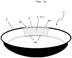
- Fig. 1a shows a first embodiment of the impact ring 1 according to the invention.
- the impact ring 1 comprises a ring-shaped body 2 made of metal, for example iron or stainless steel.
- a polymer layer 3 is arranged on the inner surface of the ring-shaped body 2.
- this is a polymer layer 3 divided into segments 3'.
- the polymer layer or the segment 3'thereof is arranged in a fastening element 4, wherein in Fig. 1 for reasons of clarity only one fastening element 4 and one segment 3' of the polymer layer 3 is shown.
- several such segments 3' and fastening element 4 are to be provided accordingly, for example 4 to 6.
- Segment 3' of polymer layer 3 is attached to the fastening element 4 by means of a (not shown) adhesive layer of adhesive, or alternatively by casting.
- the fastening element 4 has clamping connections 4a at its upper end, here in the form of two clamps, which can be attached to the upper edge of the ring-shaped body and jammed with it.
- the fastening element 4 has screw connections 4b at its lower end, here in the form of two holes. These can be brought into alignment with analog screw connections, for example holes (not shown), in the ring-shaped body 2, so that a screw connection between fastening element 4 and ring-shaped body 2 can be realized.
- Fig. 1b and 1c show a second embodiment of the impact ring 1 according to the invention.
- the impact ring 1 comprises a ring-shaped body 2 made of metal, for example iron or stainless steel.
- a polymer layer 3 is arranged on the inner surface of the ring-shaped body 2.
- this is a polymer layer 3 divided into segments 3'.
- the polymer layer 3 or the segment 3' thereof is clamped against the inner surface of the ring-shaped body 2 by means of a clamping element 5a, 5b.
- said clamping element consists of a tab 5a that is arranged over the entire upper terminal edge of the ring-shaped body 2, and is secured with the ring-shaped body 2 by means of screws 5b.
- the ring-shaped body 2 comprises a protuberance 2a at its lower terminal edge, on which the polymer layer 3 or the segment 3' thereof is supported.
- a carrier layer 5c is provided between the inner surface of the ring-shaped body 2 and the polymer layer 3 or a segment 3' thereof.
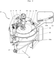
- Fig. 2 shows an embodiment of the dehulling device S according to the invention.
- the dehulling device S comprises a material inlet 9, here in the form of an inlet tube, through which material to be dehulled can be inserted into the dehulling device S.
- a material inlet 9 here in the form of an inlet tube, through which material to be dehulled can be inserted into the dehulling device S.
- an inlet funnel 10 arranged below the inlet tube 9, the good to be dehulled can be inserted into the rotor 12, through an opening on the top of rotor 12.
- the rotor 12 is hollow in its interior and has rotor segments 13 in its side wall, which are separated from each other by openings 13a (as shown in the enlarged image section). Through these openings 13a in the side wall of the rotor 12, the good to be dehulled, which is located in the interior of the rotor 12, is hurled out of the rotor 12 and against the impact ring 21 due to the centrifugal force caused by a rotation of the rotor 12 during operation. For reasons of clarity, the impact ring 1 is not shown in detail in Fig. 2 .
- the impact ring 1 can be moved with the help of a lifting unit 8 in the vertical direction (up and down).
- the vertical movement of the impact ring 1 is intended to prevent the same sections of the impact ring 1 from being exposed to an impact of goods to be dehulled during operation.
- the interior of the dehulling device S can be separated from the environment by a cover 7 and a cap 11 (which can be opened and closed).
- the cover 7 and the cap 11 are arranged on a housing 15 and connected to the housing 15 by means of a fastening 15a.
- a control cabinet 14 is attached to the housing 15, via which the dehulling device S is operated.
- Dehulled material falls from the impact ring 1 downwards through the housing 15 and enters an outlet 16, for example a trimelle.
- a control stub 17 is attached to the side of the outlet 16 in order to allow access to the interior of the dehulling device S in the event of any problems.
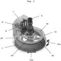
- Fig. 3 shows a further embodiment of the dehulling device S according to the invention with load sensors 20.
- the same reference signs denote the same components as in figures 1 and 2 .
- An impact ring 1 is arranged within a cap 11, which can be lifted with the help of handles 11a.
- An inner support element 19 is connected to a lifting device 8 with a drive 6, which is located under a cover 7.
- the inner support element 19 and the outer support element 18 are connected to each other via three load sensors 20 (in Fig. 3 only two of these load sensors 20 are visible, since one load sensor 20 is located behind the inlet tube 9).
- Fig. 4 shows a further embodiment of the dehulling device S according to the invention with vibration sensors 21.
- the same reference signs denote the same components as in figures 1 to 3 .
- vibration sensor 21 In the embodiment according to Fig. 4 , for reasons of clarity, only one vibration sensor 21 is shown. It is located on the inner support element 19. Of course, there may also be more than one vibration sensor 21.
- Fig. 5 shows a total weight of an impact ring (1) determined with three load sensors (20).
- the signals of the load sensors (20) are determined depending on the height of the impact ring and must be processed accordingly.
- Fig. 6 shows a frequency spectrum determined with vibration sensors (21) as a function of the height of the impact ring.
- the frequencies are grouped into individual boxes.
- the signal detected by the vibration sensors was converted from the time domain to the frequency domain to filter the signal and select only frequencies of interest.
- Fig. 7 shows an RMS value determined with vibration sensors (21) as a function of the height of the impact ring.
- the signal detected by the vibration sensors was converted from the time domain to the frequency domain to filter the signal and select only frequencies of interest.
- the filtered signal was subjected to an inverse Fourier transform. Subsequently, the RMS value of the signal obtained in this way was analyzed.
- the RMS value (also effective value) is the square mean of the signal.
- Fig. 7 shows that the RMS value is very low for a new impact ring (lower curve). In the case of an old ring (i.e. ring worn out by use), a significant increase in the RMS value can be seen. As a comparison, the RMS value for a metal ring per se (i.e. a ring without a polymer layer) is shown. It can be seen that the RMS value is significantly increased here.
Landscapes
- Life Sciences & Earth Sciences (AREA)
- Chemical & Material Sciences (AREA)
- Engineering & Computer Science (AREA)
- Food Science & Technology (AREA)
- Polymers & Plastics (AREA)
- Adjustment And Processing Of Grains (AREA)
- Combined Means For Separation Of Solids (AREA)
- Investigating Materials By The Use Of Optical Means Adapted For Particular Applications (AREA)
- Glanulating (AREA)
- Sampling And Sample Adjustment (AREA)
- Processes Of Treating Macromolecular Substances (AREA)
- Vibration Dampers (AREA)
- Apparatuses For Bulk Treatment Of Fruits And Vegetables And Apparatuses For Preparing Feeds (AREA)
- Pretreatment Of Seeds And Plants (AREA)
- Joining Of Building Structures In Genera (AREA)
- Crushing And Pulverization Processes (AREA)
Priority Applications (14)
| Application Number | Priority Date | Filing Date | Title |
|---|---|---|---|
| FIEP21200949.2T FI4163012T3 (fi) | 2021-10-05 | 2021-10-05 | Iskurengas ja parannettu kuorintalaite |
| EP21200949.2A EP4163012B1 (de) | 2021-10-05 | 2021-10-05 | Schlagring und verbesserte schälvorrichtung |
| EP25194765.1A EP4620572A3 (de) | 2021-10-05 | 2021-10-05 | Schlagring und verbesserte schälvorrichtung |
| ES21200949T ES3047032T3 (en) | 2021-10-05 | 2021-10-05 | Impact ring and improved dehulling device |
| EP25194766.9A EP4620573A3 (de) | 2021-10-05 | 2021-10-05 | Schlagring und verbesserte schälvorrichtung |
| CA3232186A CA3232186A1 (en) | 2021-10-05 | 2022-09-28 | Impact ring and improved dehulling device |
| AU2022359782A AU2022359782B2 (en) | 2021-10-05 | 2022-09-28 | Impact ring and improved dehulling device |
| CN202280061103.1A CN117957064A (zh) | 2021-10-05 | 2022-09-28 | 冲击环和改进的脱壳装置 |
| US18/697,282 US20240408606A1 (en) | 2021-10-05 | 2022-09-28 | Impact ring and improved dehulling device |
| PCT/EP2022/025450 WO2023057085A2 (en) | 2021-10-05 | 2022-09-28 | Impact ring and improved dehulling device |
| CN202610239264.5A CN121755296A (zh) | 2021-10-05 | 2022-09-28 | 冲击环和改进的脱壳装置 |
| CL2024000921A CL2024000921A1 (es) | 2021-10-05 | 2024-03-27 | Anillo de impacto y dispositivo de descascarillado mejorado |
| US19/325,020 US20260008059A1 (en) | 2021-10-05 | 2025-09-10 | Impact ring and improved dehulling device |
| CL2025004128A CL2025004128A1 (es) | 2021-10-05 | 2025-12-29 | Anillo de impacto y dispositivo de descascarillado mejorado |
Applications Claiming Priority (1)
| Application Number | Priority Date | Filing Date | Title |
|---|---|---|---|
| EP21200949.2A EP4163012B1 (de) | 2021-10-05 | 2021-10-05 | Schlagring und verbesserte schälvorrichtung |
Related Child Applications (2)
| Application Number | Title | Priority Date | Filing Date |
|---|---|---|---|
| EP25194766.9A Division EP4620573A3 (de) | 2021-10-05 | 2021-10-05 | Schlagring und verbesserte schälvorrichtung |
| EP25194765.1A Division EP4620572A3 (de) | 2021-10-05 | 2021-10-05 | Schlagring und verbesserte schälvorrichtung |
Publications (2)
| Publication Number | Publication Date |
|---|---|
| EP4163012A1 true EP4163012A1 (de) | 2023-04-12 |
| EP4163012B1 EP4163012B1 (de) | 2025-08-13 |
Family
ID=78078116
Family Applications (3)
| Application Number | Title | Priority Date | Filing Date |
|---|---|---|---|
| EP25194766.9A Pending EP4620573A3 (de) | 2021-10-05 | 2021-10-05 | Schlagring und verbesserte schälvorrichtung |
| EP21200949.2A Active EP4163012B1 (de) | 2021-10-05 | 2021-10-05 | Schlagring und verbesserte schälvorrichtung |
| EP25194765.1A Pending EP4620572A3 (de) | 2021-10-05 | 2021-10-05 | Schlagring und verbesserte schälvorrichtung |
Family Applications Before (1)
| Application Number | Title | Priority Date | Filing Date |
|---|---|---|---|
| EP25194766.9A Pending EP4620573A3 (de) | 2021-10-05 | 2021-10-05 | Schlagring und verbesserte schälvorrichtung |
Family Applications After (1)
| Application Number | Title | Priority Date | Filing Date |
|---|---|---|---|
| EP25194765.1A Pending EP4620572A3 (de) | 2021-10-05 | 2021-10-05 | Schlagring und verbesserte schälvorrichtung |
Country Status (9)
| Country | Link |
|---|---|
| US (2) | US20240408606A1 (de) |
| EP (3) | EP4620573A3 (de) |
| CN (2) | CN117957064A (de) |
| AU (1) | AU2022359782B2 (de) |
| CA (1) | CA3232186A1 (de) |
| CL (2) | CL2024000921A1 (de) |
| ES (1) | ES3047032T3 (de) |
| FI (1) | FI4163012T3 (de) |
| WO (1) | WO2023057085A2 (de) |
Citations (5)
| Publication number | Priority date | Publication date | Assignee | Title |
|---|---|---|---|---|
| US1267110A (en) * | 1916-07-22 | 1918-05-21 | Ellery P Vernon | Apparatus for treating nuts. |
| GB583188A (en) | 1944-03-29 | 1946-12-11 | Quaker Oats Co | Improvements in or relating to grain hullers |
| DE2916729A1 (de) | 1979-03-08 | 1980-09-11 | Buehler Ag Geb | Vorrichtung zum schaelen von koernigem gut |
| US4800810A (en) * | 1986-07-24 | 1989-01-31 | Yamamoto & Co. Ltd. | Impact rice huller |
| DE4136575A1 (de) * | 1991-11-07 | 1993-05-13 | Buehler Gmbh | Prallmuehle |
Family Cites Families (7)
| Publication number | Priority date | Publication date | Assignee | Title |
|---|---|---|---|---|
| JPS5087855A (de) * | 1973-12-13 | 1975-07-15 | ||
| US5146846A (en) * | 1990-05-01 | 1992-09-15 | F. H. Maloney Company | Roller assembly for grain shellers |
| CN1222408A (zh) * | 1997-12-01 | 1999-07-14 | 金子农机株式会社 | 稻谷脱壳装置 |
| JP2005103395A (ja) * | 2003-09-29 | 2005-04-21 | Iseki & Co Ltd | 研米機の研米装置 |
| CN202519954U (zh) * | 2012-04-09 | 2012-11-07 | 杨向东 | 铝玻踢脚线 |
| CN204602245U (zh) * | 2015-04-13 | 2015-09-02 | 扬州正鼎智能装备有限公司 | 一种脱壳机 |
| CN212284248U (zh) * | 2020-04-26 | 2021-01-05 | 上海华梓工程机械有限公司 | 一种反击破碎装置 |
-
2021
- 2021-10-05 EP EP25194766.9A patent/EP4620573A3/de active Pending
- 2021-10-05 EP EP21200949.2A patent/EP4163012B1/de active Active
- 2021-10-05 FI FIEP21200949.2T patent/FI4163012T3/fi active
- 2021-10-05 EP EP25194765.1A patent/EP4620572A3/de active Pending
- 2021-10-05 ES ES21200949T patent/ES3047032T3/es active Active
-
2022
- 2022-09-28 US US18/697,282 patent/US20240408606A1/en active Pending
- 2022-09-28 AU AU2022359782A patent/AU2022359782B2/en active Active
- 2022-09-28 CN CN202280061103.1A patent/CN117957064A/zh active Pending
- 2022-09-28 CN CN202610239264.5A patent/CN121755296A/zh active Pending
- 2022-09-28 WO PCT/EP2022/025450 patent/WO2023057085A2/en not_active Ceased
- 2022-09-28 CA CA3232186A patent/CA3232186A1/en active Pending
-
2024
- 2024-03-27 CL CL2024000921A patent/CL2024000921A1/es unknown
-
2025
- 2025-09-10 US US19/325,020 patent/US20260008059A1/en active Pending
- 2025-12-29 CL CL2025004128A patent/CL2025004128A1/es unknown
Patent Citations (5)
| Publication number | Priority date | Publication date | Assignee | Title |
|---|---|---|---|---|
| US1267110A (en) * | 1916-07-22 | 1918-05-21 | Ellery P Vernon | Apparatus for treating nuts. |
| GB583188A (en) | 1944-03-29 | 1946-12-11 | Quaker Oats Co | Improvements in or relating to grain hullers |
| DE2916729A1 (de) | 1979-03-08 | 1980-09-11 | Buehler Ag Geb | Vorrichtung zum schaelen von koernigem gut |
| US4800810A (en) * | 1986-07-24 | 1989-01-31 | Yamamoto & Co. Ltd. | Impact rice huller |
| DE4136575A1 (de) * | 1991-11-07 | 1993-05-13 | Buehler Gmbh | Prallmuehle |
Also Published As
| Publication number | Publication date |
|---|---|
| EP4163012B1 (de) | 2025-08-13 |
| US20260008059A1 (en) | 2026-01-08 |
| CL2024000921A1 (es) | 2024-08-30 |
| EP4620573A3 (de) | 2025-12-03 |
| EP4620572A2 (de) | 2025-09-24 |
| AU2022359782B2 (en) | 2025-11-27 |
| FI4163012T3 (fi) | 2025-09-25 |
| EP4620573A2 (de) | 2025-09-24 |
| ES3047032T3 (en) | 2025-12-03 |
| EP4620572A3 (de) | 2026-03-25 |
| WO2023057085A3 (en) | 2023-05-19 |
| CA3232186A1 (en) | 2023-06-13 |
| CL2025004128A1 (es) | 2026-01-30 |
| US20240408606A1 (en) | 2024-12-12 |
| CN117957064A (zh) | 2024-04-30 |
| AU2022359782A1 (en) | 2024-05-16 |
| WO2023057085A2 (en) | 2023-04-13 |
| CN121755296A (zh) | 2026-03-31 |
Similar Documents
| Publication | Publication Date | Title |
|---|---|---|
| US8020791B2 (en) | Pivoting shoes for an impact crushing apparatus | |
| US9861915B2 (en) | Centrifugal screen apparatus | |
| CN111065465B (zh) | 运行设备的方法、设备和计算机程序产品 | |
| EP4163012B1 (de) | Schlagring und verbesserte schälvorrichtung | |
| US10814331B2 (en) | Lifting wall arrangement and a segment of a lifting wall arrangement | |
| US6070820A (en) | Table reinforcing ring for a vertical shaft impact crusher | |
| SE0900665A1 (sv) | Hålrumsring med slitdel för en slagkross med vertikal axel, samt sätt att montera hålrumsringen | |
| US6536694B2 (en) | Gyratory crusher spider guards | |
| US7841551B2 (en) | Drop-in anvils for an impact crushing apparatus | |
| US20090194622A1 (en) | Split lid for an impact crushing apparatus | |
| US7631827B2 (en) | Floating tubular rotors for an impact crushing apparatus | |
| CA2771096C (en) | Configurations and methods for liners in grinding mill with gearless motor drive | |
| US11654444B2 (en) | Screen-type screw centrifuge | |
| CN113117871A (zh) | 维护研磨机的篦的方法以及维护装置 | |
| US20230234076A1 (en) | Baffle assemblies, nozzles, and related methods for solid discharges of centrifuge separators | |
| JPH064948Y2 (ja) | 粒大選別機における選別胴の取外し装置 | |
| US20240382973A1 (en) | Wear plate | |
| EP4108335A1 (de) | Verschleissfeste auskleidung für einen kegelbrecher |
Legal Events
| Date | Code | Title | Description |
|---|---|---|---|
| PUAI | Public reference made under article 153(3) epc to a published international application that has entered the european phase |
Free format text: ORIGINAL CODE: 0009012 |
|
| STAA | Information on the status of an ep patent application or granted ep patent |
Free format text: STATUS: THE APPLICATION HAS BEEN PUBLISHED |
|
| AK | Designated contracting states |
Kind code of ref document: A1 Designated state(s): AL AT BE BG CH CY CZ DE DK EE ES FI FR GB GR HR HU IE IS IT LI LT LU LV MC MK MT NL NO PL PT RO RS SE SI SK SM TR |
|
| P01 | Opt-out of the competence of the unified patent court (upc) registered |
Effective date: 20230523 |
|
| STAA | Information on the status of an ep patent application or granted ep patent |
Free format text: STATUS: REQUEST FOR EXAMINATION WAS MADE |
|
| 17P | Request for examination filed |
Effective date: 20230913 |
|
| RBV | Designated contracting states (corrected) |
Designated state(s): AL AT BE BG CH CY CZ DE DK EE ES FI FR GB GR HR HU IE IS IT LI LT LU LV MC MK MT NL NO PL PT RO RS SE SI SK SM TR |
|
| STAA | Information on the status of an ep patent application or granted ep patent |
Free format text: STATUS: EXAMINATION IS IN PROGRESS |
|
| 17Q | First examination report despatched |
Effective date: 20240828 |
|
| REG | Reference to a national code |
Ref legal event code: R079 Ref country code: DE Ref legal event code: R079 Ref document number: 602021036002 Country of ref document: DE Free format text: PREVIOUS MAIN CLASS: B02B0003000000 Ipc: A23N0005000000 |
|
| GRAP | Despatch of communication of intention to grant a patent |
Free format text: ORIGINAL CODE: EPIDOSNIGR1 |
|
| STAA | Information on the status of an ep patent application or granted ep patent |
Free format text: STATUS: GRANT OF PATENT IS INTENDED |
|
| RIC1 | Information provided on ipc code assigned before grant |
Ipc: B02B 3/00 20060101ALI20250219BHEP Ipc: A23N 5/00 20060101AFI20250219BHEP |
|
| INTG | Intention to grant announced |
Effective date: 20250310 |
|
| GRAS | Grant fee paid |
Free format text: ORIGINAL CODE: EPIDOSNIGR3 |
|
| GRAA | (expected) grant |
Free format text: ORIGINAL CODE: 0009210 |
|
| STAA | Information on the status of an ep patent application or granted ep patent |
Free format text: STATUS: THE PATENT HAS BEEN GRANTED |
|
| AK | Designated contracting states |
Kind code of ref document: B1 Designated state(s): AL AT BE BG CH CY CZ DE DK EE ES FI FR GB GR HR HU IE IS IT LI LT LU LV MC MK MT NL NO PL PT RO RS SE SI SK SM TR |
|
| REG | Reference to a national code |
Ref country code: GB Ref legal event code: FG4D |
|
| REG | Reference to a national code |
Ref country code: CH Ref legal event code: EP |
|
| REG | Reference to a national code |
Ref country code: DE Ref legal event code: R096 Ref document number: 602021036002 Country of ref document: DE |
|
| REG | Reference to a national code |
Ref country code: IE Ref legal event code: FG4D |
|
| REG | Reference to a national code |
Ref country code: SE Ref legal event code: TRGR |
|
| REG | Reference to a national code |
Ref country code: FI Ref legal event code: FGE |
|
| REG | Reference to a national code |
Ref country code: CH Ref legal event code: U11 Free format text: ST27 STATUS EVENT CODE: U-0-0-U10-U11 (AS PROVIDED BY THE NATIONAL OFFICE) Effective date: 20251103 |
|
| REG | Reference to a national code |
Ref country code: ES Ref legal event code: FG2A Ref document number: 3047032 Country of ref document: ES Kind code of ref document: T3 Effective date: 20251203 |
|
| REG | Reference to a national code |
Ref country code: NL Ref legal event code: MP Effective date: 20250813 |
|
| PG25 | Lapsed in a contracting state [announced via postgrant information from national office to epo] |
Ref country code: IS Free format text: LAPSE BECAUSE OF FAILURE TO SUBMIT A TRANSLATION OF THE DESCRIPTION OR TO PAY THE FEE WITHIN THE PRESCRIBED TIME-LIMIT Effective date: 20251213 |
|
| PGFP | Annual fee paid to national office [announced via postgrant information from national office to epo] |
Ref country code: DE Payment date: 20251020 Year of fee payment: 5 |
|
| PGFP | Annual fee paid to national office [announced via postgrant information from national office to epo] |
Ref country code: GB Payment date: 20251024 Year of fee payment: 5 |
|
| PG25 | Lapsed in a contracting state [announced via postgrant information from national office to epo] |
Ref country code: NO Free format text: LAPSE BECAUSE OF FAILURE TO SUBMIT A TRANSLATION OF THE DESCRIPTION OR TO PAY THE FEE WITHIN THE PRESCRIBED TIME-LIMIT Effective date: 20251113 |
|
| REG | Reference to a national code |
Ref country code: LT Ref legal event code: MG9D |
|
| PG25 | Lapsed in a contracting state [announced via postgrant information from national office to epo] |
Ref country code: PT Free format text: LAPSE BECAUSE OF FAILURE TO SUBMIT A TRANSLATION OF THE DESCRIPTION OR TO PAY THE FEE WITHIN THE PRESCRIBED TIME-LIMIT Effective date: 20251215 |
|
| PGFP | Annual fee paid to national office [announced via postgrant information from national office to epo] |
Ref country code: FI Payment date: 20251030 Year of fee payment: 5 |
|
| PG25 | Lapsed in a contracting state [announced via postgrant information from national office to epo] |
Ref country code: HR Free format text: LAPSE BECAUSE OF FAILURE TO SUBMIT A TRANSLATION OF THE DESCRIPTION OR TO PAY THE FEE WITHIN THE PRESCRIBED TIME-LIMIT Effective date: 20250813 Ref country code: NL Free format text: LAPSE BECAUSE OF FAILURE TO SUBMIT A TRANSLATION OF THE DESCRIPTION OR TO PAY THE FEE WITHIN THE PRESCRIBED TIME-LIMIT Effective date: 20250813 |
|
| PG25 | Lapsed in a contracting state [announced via postgrant information from national office to epo] |
Ref country code: GR Free format text: LAPSE BECAUSE OF FAILURE TO SUBMIT A TRANSLATION OF THE DESCRIPTION OR TO PAY THE FEE WITHIN THE PRESCRIBED TIME-LIMIT Effective date: 20251114 |
|
| PGFP | Annual fee paid to national office [announced via postgrant information from national office to epo] |
Ref country code: CH Payment date: 20251103 Year of fee payment: 5 Ref country code: SE Payment date: 20251023 Year of fee payment: 5 |
|
| PG25 | Lapsed in a contracting state [announced via postgrant information from national office to epo] |
Ref country code: LV Free format text: LAPSE BECAUSE OF FAILURE TO SUBMIT A TRANSLATION OF THE DESCRIPTION OR TO PAY THE FEE WITHIN THE PRESCRIBED TIME-LIMIT Effective date: 20250813 |
|
| PG25 | Lapsed in a contracting state [announced via postgrant information from national office to epo] |
Ref country code: PL Free format text: LAPSE BECAUSE OF FAILURE TO SUBMIT A TRANSLATION OF THE DESCRIPTION OR TO PAY THE FEE WITHIN THE PRESCRIBED TIME-LIMIT Effective date: 20250813 |
|
| PGFP | Annual fee paid to national office [announced via postgrant information from national office to epo] |
Ref country code: BG Payment date: 20251023 Year of fee payment: 5 |
|
| PG25 | Lapsed in a contracting state [announced via postgrant information from national office to epo] |
Ref country code: RS Free format text: LAPSE BECAUSE OF FAILURE TO SUBMIT A TRANSLATION OF THE DESCRIPTION OR TO PAY THE FEE WITHIN THE PRESCRIBED TIME-LIMIT Effective date: 20251113 |
|
| PGFP | Annual fee paid to national office [announced via postgrant information from national office to epo] |
Ref country code: ES Payment date: 20251114 Year of fee payment: 5 |
|
| REG | Reference to a national code |
Ref country code: AT Ref legal event code: MK05 Ref document number: 1823688 Country of ref document: AT Kind code of ref document: T Effective date: 20250813 |
|
| PG25 | Lapsed in a contracting state [announced via postgrant information from national office to epo] |
Ref country code: RO Free format text: LAPSE BECAUSE OF FAILURE TO SUBMIT A TRANSLATION OF THE DESCRIPTION OR TO PAY THE FEE WITHIN THE PRESCRIBED TIME-LIMIT Effective date: 20250813 |
|
| PG25 | Lapsed in a contracting state [announced via postgrant information from national office to epo] |
Ref country code: SM Free format text: LAPSE BECAUSE OF FAILURE TO SUBMIT A TRANSLATION OF THE DESCRIPTION OR TO PAY THE FEE WITHIN THE PRESCRIBED TIME-LIMIT Effective date: 20250813 |
|
| PG25 | Lapsed in a contracting state [announced via postgrant information from national office to epo] |
Ref country code: DK Free format text: LAPSE BECAUSE OF FAILURE TO SUBMIT A TRANSLATION OF THE DESCRIPTION OR TO PAY THE FEE WITHIN THE PRESCRIBED TIME-LIMIT Effective date: 20250813 |
|
| PG25 | Lapsed in a contracting state [announced via postgrant information from national office to epo] |
Ref country code: AT Free format text: LAPSE BECAUSE OF FAILURE TO SUBMIT A TRANSLATION OF THE DESCRIPTION OR TO PAY THE FEE WITHIN THE PRESCRIBED TIME-LIMIT Effective date: 20250813 |
|
| PG25 | Lapsed in a contracting state [announced via postgrant information from national office to epo] |
Ref country code: IT Free format text: LAPSE BECAUSE OF FAILURE TO SUBMIT A TRANSLATION OF THE DESCRIPTION OR TO PAY THE FEE WITHIN THE PRESCRIBED TIME-LIMIT Effective date: 20250813 |
|
| PG25 | Lapsed in a contracting state [announced via postgrant information from national office to epo] |
Ref country code: CZ Free format text: LAPSE BECAUSE OF FAILURE TO SUBMIT A TRANSLATION OF THE DESCRIPTION OR TO PAY THE FEE WITHIN THE PRESCRIBED TIME-LIMIT Effective date: 20250813 |
|
| PG25 | Lapsed in a contracting state [announced via postgrant information from national office to epo] |
Ref country code: EE Free format text: LAPSE BECAUSE OF FAILURE TO SUBMIT A TRANSLATION OF THE DESCRIPTION OR TO PAY THE FEE WITHIN THE PRESCRIBED TIME-LIMIT Effective date: 20250813 Ref country code: SK Free format text: LAPSE BECAUSE OF FAILURE TO SUBMIT A TRANSLATION OF THE DESCRIPTION OR TO PAY THE FEE WITHIN THE PRESCRIBED TIME-LIMIT Effective date: 20250813 |