EP4163076B1 - Mandrin d'empilage d'outillage rapide et procédé de moulage d'une piece - Google Patents
Mandrin d'empilage d'outillage rapide et procédé de moulage d'une piece Download PDFInfo
- Publication number
- EP4163076B1 EP4163076B1 EP22180998.1A EP22180998A EP4163076B1 EP 4163076 B1 EP4163076 B1 EP 4163076B1 EP 22180998 A EP22180998 A EP 22180998A EP 4163076 B1 EP4163076 B1 EP 4163076B1
- Authority
- EP
- European Patent Office
- Prior art keywords
- face sheet
- skin
- layup mandrel
- rib structure
- ribs
- Prior art date
- Legal status (The legal status is an assumption and is not a legal conclusion. Google has not performed a legal analysis and makes no representation as to the accuracy of the status listed.)
- Active
Links
Images









Classifications
-
- B—PERFORMING OPERATIONS; TRANSPORTING
- B29—WORKING OF PLASTICS; WORKING OF SUBSTANCES IN A PLASTIC STATE IN GENERAL
- B29C—SHAPING OR JOINING OF PLASTICS; SHAPING OF MATERIAL IN A PLASTIC STATE, NOT OTHERWISE PROVIDED FOR; AFTER-TREATMENT OF THE SHAPED PRODUCTS, e.g. REPAIRING
- B29C70/00—Shaping composites, i.e. plastics material comprising reinforcements, fillers or preformed parts, e.g. inserts
- B29C70/04—Shaping composites, i.e. plastics material comprising reinforcements, fillers or preformed parts, e.g. inserts comprising reinforcements only, e.g. self-reinforcing plastics
- B29C70/28—Shaping operations therefor
- B29C70/40—Shaping or impregnating by compression not applied
- B29C70/42—Shaping or impregnating by compression not applied for producing articles of definite length, i.e. discrete articles
- B29C70/44—Shaping or impregnating by compression not applied for producing articles of definite length, i.e. discrete articles using isostatic pressure, e.g. pressure difference-moulding, vacuum bag-moulding, autoclave-moulding or expanding rubber-moulding
-
- B—PERFORMING OPERATIONS; TRANSPORTING
- B29—WORKING OF PLASTICS; WORKING OF SUBSTANCES IN A PLASTIC STATE IN GENERAL
- B29C—SHAPING OR JOINING OF PLASTICS; SHAPING OF MATERIAL IN A PLASTIC STATE, NOT OTHERWISE PROVIDED FOR; AFTER-TREATMENT OF THE SHAPED PRODUCTS, e.g. REPAIRING
- B29C33/00—Moulds or cores; Details thereof or accessories therefor
- B29C33/44—Moulds or cores; Details thereof or accessories therefor with means for, or specially constructed to facilitate, the removal of articles, e.g. of undercut articles
- B29C33/48—Moulds or cores; Details thereof or accessories therefor with means for, or specially constructed to facilitate, the removal of articles, e.g. of undercut articles with means for collapsing or disassembling
- B29C33/485—Moulds or cores; Details thereof or accessories therefor with means for, or specially constructed to facilitate, the removal of articles, e.g. of undercut articles with means for collapsing or disassembling cores or mandrels
-
- B—PERFORMING OPERATIONS; TRANSPORTING
- B29—WORKING OF PLASTICS; WORKING OF SUBSTANCES IN A PLASTIC STATE IN GENERAL
- B29C—SHAPING OR JOINING OF PLASTICS; SHAPING OF MATERIAL IN A PLASTIC STATE, NOT OTHERWISE PROVIDED FOR; AFTER-TREATMENT OF THE SHAPED PRODUCTS, e.g. REPAIRING
- B29C33/00—Moulds or cores; Details thereof or accessories therefor
- B29C33/0011—Moulds or cores; Details thereof or accessories therefor thin-walled moulds
-
- B—PERFORMING OPERATIONS; TRANSPORTING
- B29—WORKING OF PLASTICS; WORKING OF SUBSTANCES IN A PLASTIC STATE IN GENERAL
- B29C—SHAPING OR JOINING OF PLASTICS; SHAPING OF MATERIAL IN A PLASTIC STATE, NOT OTHERWISE PROVIDED FOR; AFTER-TREATMENT OF THE SHAPED PRODUCTS, e.g. REPAIRING
- B29C70/00—Shaping composites, i.e. plastics material comprising reinforcements, fillers or preformed parts, e.g. inserts
- B29C70/04—Shaping composites, i.e. plastics material comprising reinforcements, fillers or preformed parts, e.g. inserts comprising reinforcements only, e.g. self-reinforcing plastics
- B29C70/28—Shaping operations therefor
- B29C70/30—Shaping by lay-up, i.e. applying fibres, tape or broadsheet on a mould, former or core; Shaping by spray-up, i.e. spraying of fibres on a mould, former or core
- B29C70/34—Shaping by lay-up, i.e. applying fibres, tape or broadsheet on a mould, former or core; Shaping by spray-up, i.e. spraying of fibres on a mould, former or core and shaping or impregnating by compression, i.e. combined with compressing after the lay-up operation
- B29C70/342—Shaping by lay-up, i.e. applying fibres, tape or broadsheet on a mould, former or core; Shaping by spray-up, i.e. spraying of fibres on a mould, former or core and shaping or impregnating by compression, i.e. combined with compressing after the lay-up operation using isostatic pressure
-
- B—PERFORMING OPERATIONS; TRANSPORTING
- B29—WORKING OF PLASTICS; WORKING OF SUBSTANCES IN A PLASTIC STATE IN GENERAL
- B29C—SHAPING OR JOINING OF PLASTICS; SHAPING OF MATERIAL IN A PLASTIC STATE, NOT OTHERWISE PROVIDED FOR; AFTER-TREATMENT OF THE SHAPED PRODUCTS, e.g. REPAIRING
- B29C33/00—Moulds or cores; Details thereof or accessories therefor
- B29C33/38—Moulds or cores; Details thereof or accessories therefor characterised by the material or the manufacturing process
- B29C33/3842—Manufacturing moulds, e.g. shaping the mould surface by machining
-
- Y—GENERAL TAGGING OF NEW TECHNOLOGICAL DEVELOPMENTS; GENERAL TAGGING OF CROSS-SECTIONAL TECHNOLOGIES SPANNING OVER SEVERAL SECTIONS OF THE IPC; TECHNICAL SUBJECTS COVERED BY FORMER USPC CROSS-REFERENCE ART COLLECTIONS [XRACs] AND DIGESTS
- Y02—TECHNOLOGIES OR APPLICATIONS FOR MITIGATION OR ADAPTATION AGAINST CLIMATE CHANGE
- Y02T—CLIMATE CHANGE MITIGATION TECHNOLOGIES RELATED TO TRANSPORTATION
- Y02T50/00—Aeronautics or air transport
- Y02T50/40—Weight reduction
Definitions
- the present disclosure relates to systems and methods for manufacturing composite parts.
- US2018/236638 concerns a tooling assembly, for use with a panel defining a tool-side surface and the tool-side surface defining a profile.
- the tooling assembly includes a base, a plurality of support members fixedly attached to the base, a plurality of frames, and a securing system.
- the frames each define an upper surface, where each support member is releasably coupled to a corresponding frame by a fastening system.
- the upper surfaces of the frames are each shaped to correspond with a portion of the profile of the tool-side surface of the panel.
- the securing system is for providing a suction force configured to releasably secure the panel against the upper surface of the frames.
- EP0197709 concerns a vacuum bag moulding of carbon-fibre-reinforced-plastics, sheet-form, heat-cured articles net-to-size, with formed edges, accomplished by providing mold periphery elements of corresponding moulding edge profile on the moulding face of moulding tooling, with provision for sliding of periphery elements across the moulding face during curing.
- a layup mandrel comprising:
- the layup mandrel may have one or more of the following features:
- the layup mandrel further comprises a base comprising an assembly jig holding the ribs during assembly of the rib structure.
- the layup mandrel further comprises a base comprising movable vanes for positioning and holding the ribs during assembly of the rib structure, wherein the base is modular for assembly of different configurations of the ribs.
- the layup mandrel further comprises a detachable base comprising one or more handles for transporting or handling the layup mandrel attached to the detachable base.
- the handles comprise one or more openings capable of receiving at least one tool selected from:
- the rib structure comprises tabs forming joints with the detachable base.
- the rib structure comprises or consists essentially of the composite material.
- the skin is non-porous so that the skin has vacuum integrity when the skin is sealed to a bagging film so as to form a bag containing the part, the vacuum integrity maintaining a vacuum in the bag used for pressing the part against the skin during curing of the composite material.
- the rib structure comprises a frame supporting the ribs and the frame comprises openings allowing airflow under the skin for increasing heat transfer during the curing.
- the part comprises a face sheet and the face sheet is bonded to the surface so that the rib structure comprises an integrated stiffener for the face sheet.
- layup mandrel further comprises a face sheet on the skin, wherein the face sheet has a surface having the curvature of the lofted surface; wherein the curvature molds the part comprising an aircraft part pressed against the face sheet during curing of the part.
- the surface comprises a machined surface.
- the face sheet includes bushings or locators.
- the rib structure comprises a frame supporting the ribs, the ribs comprise faces and edges, the faces comprise cross-sectional surfaces of the rib structure, the edges define the lofted surface, and the skin is disposed on the edges.
- the rib structure comprises a notch holding a block having a block surface including a contour with higher resolution for molding a section of the part.
- a method of laying up a face sheet comprising:
- the method further comprises:
- the method comprises machining a surface of the face sheet using only one machining step to form a machined surface, the pressure pressing the part against the machined surface during the molding.
- the method comprises cutting a plurality of the ribs from one or more panels comprising the composite material, wherein each of the ribs have one of the faces and one of the edges shaped to form the lofted surface.
- the method comprises detaching the base and re-using the base to assemble another one of the layup mandrels.
- Fig. 1 illustrates a layup mandrel 100 (e.g., rapid tooling layup mandrel) comprising a rib structure 102 comprising ribs 104 defining a lofted surface 106; a skin 108 attached to and supported by the rib structure 102; and a face sheet 111 on the skin 108.
- the face sheet 111 has a surface 110 having a curvature 112 defined by the lofted surface 106 so that the mandrel 100 shapes a part pressed against the surface 110 during curing of the part.
- the layup mandrel 100 further comprises a base 114 comprising an assembly jig 116 holding the ribs 104 during assembly of the rib structure 102.
- Fig. 2 illustrates the base 114 further includes handles 200 (e.g., grips or tool handling structures) for handling and lifting the layup mandrel 100 attached to the base 114.
- the handles 200 or tool handling structures comprise one or more openings 202 capable of receiving at least one tool selected from one or more forklift forks, one or more lifting hooks, or one or more attachments for connecting casters so that the base 114 is capable of being at least lifted or transported by the tool (e.g., using a fork lift, a crane, or the casters).
- Fig. 2 further illustrates an example assembly jig 116 comprises supports 203 (e.g., jigs or vanes 204) wherein the supports 203 comprise mounts positioning and holding the ribs 104 during the assembly of the rib structure 102.
- the base is modular for assembly of different configurations of the ribs 104.
- the supports 203 e.g., vanes or mounts
- the pieces 207 that run across the width of the base 114 are stiffeners to keep the base 114 flat and provide the base 114 its structural integrity.
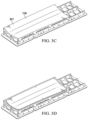
- Figs. 3A-3F illustrate a method of making a layup mandrel and molding a part.
- Fig. 3A illustrates obtaining a base of the correct size to build the layup mandrel.
- the base is configured for building or stacking up a plurality of different layup mandrels.
- Fig. 3B illustrates bonding a set of ribs together using the base as an assembly jig, so as to form the set of ribs into a rib structure.
- the ribs are made of the same composite material (e.g., carbon fiber, fiberglass) as the part being molded using the layup mandrel.
- Fig. 3C illustrates bonding a skin (e.g., loft skin) to the rib structure, so as to create a shape for the face sheet comprising the layup mandrel tool surface.
- the skin is stretched over and then bonded under tension to the rib structure to form a drum-like surface.
- Example materials for the skin include, but are not limited to, a material that bonds well to the rib structure and ultimately the face sheet.
- Example properties of the skin include, but are not limited to, the skin having at least one of a stiffness, durability, and an ability to withstand extreme temperatures, e.g., to match different application requirements.
- the stiffness, durability and ability to withstand extreme temperatures are tailored by selection of the one or more different materials and/or thickness of the skin.
- the loft skin comprises a mesh enabling three dimensional printing or additive manufacturing of the face sheet.
- the cured face sheet includes features or functionality used during layup mandrel builds (e.g., scribes, optical tooling points, pad-ups, or drill starts).
- optical tooling points include, but are not limited to, a tooling ball (e.g., steel sphere) having a stem that slips into a hole in the layup mandrel and allowing the tooling ball to be probed so as to locate the tooling ball.
- Example molding conditions for the face sheet include, but are not limited to, conditions wherein the rib structure and the skin (in combination) mold the face sheet during a curing process.
- Fig. 3E illustrates after curing, optionally machining (e.g., computer numerical control, or CNC milling), finishing, or smoothing the surface of the face sheet (comprising the surface of the layup mandrel) to obtain a final contour shape of the layup mandrel.
- machining e.g., computer numerical control, or CNC milling
- Fig. 3F illustrates using the layup mandrel to produce (mold) the part 300 against the face sheet.
- the use of the base is optional. In one or more examples the base is removed prior to molding the part.
- the curing temperature depends on the material being used for the face sheet and/or part.
- Example curing temperatures are listed in the table below. Material Curing Temperature Tooling paste Room temperature Fiberglass 250° Carbon Fiber with epoxy resin 350°- 450°C (450°C when resin is BMI resin Thermoplastic materials 700°+
- layup mandrel tools are designed to account for stresses resulting from the different coefficient of thermal expansion (CTE) and contraction between different components during high temperature curing.
- CTE coefficient of thermal expansion
- Embodiments described herein fabricate the rib structure, the face sheet, and the part being molded by the layup mandrel with the same materials to ensure CTE compatibility between the layup mandrel and the part.
- the skin does not need to be manufactured with the same material as the rib structure, part, or face sheet because the thickness of the skin is so thin that its CTE does not significantly impact the contraction and expansion of the layup mandrel.
- Fig. 4 illustrates an example wherein the ribs 104 are slats 400 cut from a large stock panel using water jet cutting.
- each rib 104 including ribs 104 having a different shape, have a notch 401 for identifying the ordering of the ribs 104 during the assembly.
- the ribs 104 comprise faces 402 and edges 404, the faces 402 comprise cross-sectional surfaces 406 of the rib structure, and the edges 404 define the lofted surface 106.
- Each notch 401 is inserted into and held in a corresponding slot 408 in a rail 410 so as to form the rib structure 102 comprising a set of ribs 104 secured in a frame 412.
- the plan (including the shape, dimensions, and nesting) of the ribs 104 is generated using a profile automatically generated according to a design required by a customer.
- Example design methods include, but are not limited to, the plan of each of the ribs being automatically designed using relations in computer aided design (CAD) without coding or scripting.
- CAD computer aided design
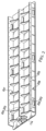
- Fig. 5 illustrates a set of ribs 104 assembled into a rib structure 102 creating the lofted surface 106 defining a rough shape for the face sheet.
- the spacing S of the ribs, frequency, and pattern are designed to optimally support the desired curvature and surface profile resolution of the part being molded. In one or more examples, in areas requiring higher contour, the spacing between the ribs is decreased for higher resolution.
- Example spacings include a spacing S in a range of 1-10 inches.
- Fig. 6 illustrates the rib structure 102 permanently bonded to the skin 108, so that after the face sheet is cured on the skin 108, the rib structure 102 comprises an integrated stiffener 600 for the skin 108 and the face sheet.
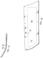
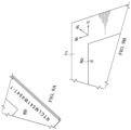
- Fig. 7A-7B illustrate machining of the face sheet 111 along a trajectory 700 that consumes any error in the contour of the surface 110 of the face sheet 111 (as defined or formed by the skin on the rib structure), thereby forming a machined surface 702.
- Figs. 10A-10C illustrate an example wherein the rib structure 102 comprises joints 1002 (e.g., finger joints) comprising tabs 1004.
- the tabs 1004 comprise holes 1006 for fasteners 1008 (e.g., pins or screws), wherein the fasteners 1008 are used to fasten the rib structure 102 to the base 114 along the length of the rib structure 102 and along a cross-section of the rib structure 102.
- the rib structure 102 further includes curved concave sections 1010 defining openings 1011 that increase airflow 1012 under the rib structure.
- the airflow 1012 facilitates heat transfer during the molding process.
- the curing typically, but not always, requires heating the material to cure temperature.
- Figs. 12A-12B illustrate a layup mandrel 100 having a shape configured to mold an aircraft part (e.g., a wing leading edge).
- the layup mandrel 100 comprises a rib structure 102 comprising female connectors for connecting to the base 114.
- Figs. 13 , 14 , and 15 illustrate a system 1300 and method for molding a part 300 using the layup mandrel 100.
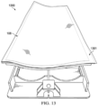
- Fig. 13 is a perspective view illustrating a bagging film 1301 on the layup mandrel 100, wherein the bagging film 1301 is used to seal the part comprising a face sheet 111 during curing of the face sheet 111.
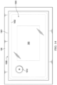
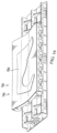
- Figs. 14 and 15 illustrate the system 1300 further comprises double sided adhesive 1502 (e.g., tacky tape), wherein a first side 1504 of the adhesive 1502 contacts the skin 108 and forms a continuous sealed border or perimeter 1506 around an entirety of the part 300.
- the bagging film 1301 is sealed to a second side 1510 of the double sided adhesive 1502 around the whole perimeter 1506, so as to form an airtight bag 1505 comprising the surface 301 of the skin 108, the double sided adhesive 1502, and the bagging film 1301.
- Figs. 14 and 15 further illustrate the system 1300 comprises a vacuum port 1512 allowing access to a sealed volume of the bag 1505 while maintaining vacuum integrity of the bag 1505 during the molding process.
- the system 1300 further comprises a vacuum pump 1514 connected to the vacuum port for sucking air 1503 from the bag 1505 via the vacuum port 1512, thereby evacuating the bag 1505 and forming a vacuum 1513 inside the bag 1505.
- atmospheric pressure 1516 outside the evacuated bag 1505 presses on the part 300 over an entire surface of the evacuated bag 1505, so as to press the part 300 against the layup mandrel 100 (and molding the part according to contour of the lofted surface 106).
- the part 300 is pressed against the layup mandrel with a pressure, e.g., in a range from atmospheric pressure to 200 pounds per square inch (e.g., 90-100 pounds per square inch).
- the molding further comprises heating (e.g., at a temperature in a range of room temperature to more than 700 degrees Celsius) the part 300 so as to cure the part 300 while the part 300 is being molded using the pressure.
- the part or face sheet is molded and cured in an autoclave. However, an autoclave is not necessary.
- the part or face sheet are molded and cured under pressure (e.g., atmospheric pressure), e.g., subjected and applied using the evacuated bag 1505.
- the part 300 being molded on the layup mandrel 100 comprises a face sheet 111 bonded to or attached to the skin 108 (so that the face sheet is molded against the skin 108).
- the layup mandrel 100 further comprising the face sheet 111 is used to mold another part 300 using the system 1300, so that the part 300 is now molded against the surface 110 of the face sheet 111.
- the contour of the surface 110, 301 is determined by the predetermined design of the lofted surface 106 and optionally also the finished profile of the surface 702 of the face sheet 111 (e.g., as formed by machining). In one more examples, only one machining operation is used to form or machine the surface 110 into the machined surface 702 against which the part 300 is molded.
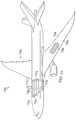
- Fig. 17 is a schematic of an aircraft 1700 comprising parts 300 comprising aircraft parts 1702 manufactured and moldable using the layup mandrel 100.
- Fig. 17 illustrates example aircraft parts 1702 include, but are not limited to, a wing skin 1704 (including wing leading edge 1705), a wing spar 1706, a longeron 1708, a bulkhead 1710, a fuselage section 1712, or fuselage skin 1714.
- Fig. 18 is a flowchart illustrating a method of laying up a face sheet, comprising the following steps.
- Block 1800 represents obtaining a base comprising an assembly jig.
Landscapes
- Engineering & Computer Science (AREA)
- Mechanical Engineering (AREA)
- Chemical & Material Sciences (AREA)
- Composite Materials (AREA)
- Moulding By Coating Moulds (AREA)
- Casting Or Compression Moulding Of Plastics Or The Like (AREA)
Claims (15)
- Mandrin de superposition (100) pour mouler une pièce comprenant ou consistant en essentiellement un matériau composite, le mandrin de superposition comprenant :une structure nervurée (102) comprenant des nervures (104) définissant une surface surélevée (106) ; etune peau (108) fixée à et supportée par la structure nervurée (102), dans lequel :la peau (108) a une surface (301) ayant une courbure (112) de la surface surélevée (106) ;les nervures (104) sont disposées pour façonner au moins partiellement la courbure (112) moulant ladite pièce (300) pressée contre la peau (108) pendant le durcissement de la pièce (300) ;une semelle (111) sur la peau (108) ;un film d'ensachage scellé à la semelle de manière à former un sac (1505) contenant la pièce, et évacuant le sac (1505) de manière à appliquer la pression pressant la pièce contre la semelle, de manière à finir le moulage de la pièce contre la semelle.
- Mandrin de superposition (100) selon la revendication 1, comprenant en outre une base (114) comprenant un bâti de montage (116) retenant les nervures (104) pendant le montage de la structure nervurée (102).
- Mandrin de superposition (100) selon l'une quelconque des revendications 1 à 2, comprenant en outre une base (114) comprenant des aubes (204) pour positionner et retenir les nervures (104) pendant le montage de la structure nervurée (102), dans lequel la base (114) est modulaire pour le montage de différentes configurations des nervures (104).
- Mandrin de superposition (100) selon l'une quelconque des revendications 1 à 3, comprenant en outre une base (114) détachable comprenant une ou plusieurs poignées (200) pour transporter ou manipuler le mandrin de superposition (100) fixé à la base (114) détachable, dans lequel les poignées comprennent une ou plusieurs ouvertures (202) capables de recevoir au moins un outil sélectionné parmi :une ou plusieurs fourches de chariot élévateur,un ou plusieurs crochets de levage, ouun ou plusieurs accessoires pour relier une ou plusieurs couleuses,de telle façon que la base (114) détachable soit capable d'être au moins levée ou transportée par l'outil lorsque l'outil ou les un ou plusieurs accessoires sont insérés dans les ouvertures (202).
- Mandrin de superposition (100) selon l'une quelconque des revendications 1 à 4, dans lequel la structure nervurée (102) comprend des pattes (1004) formant des jointures (1002) avec la base (114) détachable.
- Mandrin de superposition (100) selon l'une quelconque des revendications 1 à 5, dans lequel la peau (108) est non poreuse de telle façon que la peau (108) ait une intégrité sous vide lorsque la peau (108) est scellée à un film d'ensachage (1301) de manière à former un sac (1505) contenant la pièce, l'intégrité sous vide maintenant un vide utilisé pour presser la pièce contre la surface (110) pendant le durcissement du matériau composite en utilisant l'autoclave.
- Mandrin de superposition (100) selon l'une quelconque des revendications 1 à 6, dans lequel la structure nervurée (102) comprend une monture (500) supportant les nervures (104) et la monture (500) comprend des ouvertures (1011) permettant un écoulement d'air (1012) sous la peau (108) pour un transfert de chaleur pendant le durcissement.
- Mandrin de superposition selon la revendication 1, comprenant en outre une semelle (111) sur la peau (108), dans lequel :la semelle a une seconde surface (110) ayant la courbure (112) de la surface surélevée (106) ; etla courbure (112) moule la pièce (300) de telle façon que la pièce est pressée contre la semelle (111) pendant le durcissement de la pièce (300).
- Mandrin de superposition selon la revendication 8, dans lequel la semelle (111) est liée à la surface (301) de la peau de telle façon que la structure nervurée (102) comprenne un raidisseur intégré (600) pour la semelle (111).
- Mandrin de superposition (100) selon la revendication 1, dans lequel :la structure nervurée (102) comprend une monture (500) supportant les nervures (104),les nervures (104) comprennent des faces (402) et des arêtes (404),les faces (402) comprennent des surfaces en coupe transversale de la structure nervurée (102), etles arêtes (404) définissent la surface surélevée (106), etla peau (108) est disposée sur les arêtes (404).
- Mandrin de superposition (100) selon la revendication 1, dans lequel la structure nervurée (102) comprend une encoche (800) retenant un bloc (802) ayant une surface de bloc (804) comportant un contour (806) avec une plus grande résolution pour le moulage d'une section de la pièce (300).
- Procédé de superposition d'une semelle (111), comprenant :l'obtention d'une base (114) comprenant un bâti de montage (116) ;le montage d'une pluralité de nervures (104) dans une monture (500) sur la base (114), de manière à former une structure nervurée (102), dans lequel les nervures (104) comprennent des faces (402) et des arêtes (404), les faces (402) comprennent des surfaces en coupe transversale de la structure nervurée (102), et les arêtes (404) définissent une surface surélevée (106) ;la liaison d'une peau (108) aux arêtes (404) de telle façon que la peau (108) ait une surface (301) façonnée par les arêtes (404) et une courbure (112) de la surface surélevée (106) ;la superposition d'une semelle (111) comprenant un matériau composite sur la surface (301), de manière à mouler au moins partiellement la semelle (111) contre la surface (301) ;le durcissement de la semelle (111) contre la peau (108), comprenant :le scellement d'un film d'ensachage (1301) à la peau (108) de manière à former un sac (1505) contenant la semelle (111) ; etl'évacuation du sac (1505) de manière à appliquer une pression pressant la semelle (111) contre la surface (301) de manière à finir le moulage de la semelle (111) contre la peau ;la superposition d'une pièce (300) sur la semelle (111) de manière à mouler au moins partiellement la pièce (300) contre la semelle (111) ;le durcissement de la pièce (300), comprenant :le scellement du film d'ensachage (1301) à la semelle (111) de manière à former le sac (1505) contenant la pièce (300) ; etl'évacuation du sac (1505) de manière à appliquer la pression pressant la pièce (300) contre la semelle (111), de manière à finir le moulage de la pièce (300) contre la semelle (111).
- Procédé selon la revendication 12, en outre après le durcissement de la semelle (111), comprenant l'usinage d'une seconde surface (110) de la semelle (111) en utilisant uniquement une étape d'usinage pour former une surface usinée (702), dans lequel la pression presse la pièce (300) contre la surface usinée (702) pendant le moulage.
- Procédé selon l'une quelconque des revendications 12 à 13, comprenant en outre la coupe d'une pluralité des nervures (104) à partir d'un ou plusieurs panneaux comprenant le matériau composite, dans lequel chacune des nervures (104) a une des faces (402) et une des arêtes (404) façonnées pour former la surface surélevée (106).
- Procédé selon l'une quelconque des revendications 12 à 14, comprenant en outre le détachement de la base (114) et la réutilisation de la base (114) pour monter un mandrin de superposition différent.
Applications Claiming Priority (1)
| Application Number | Priority Date | Filing Date | Title |
|---|---|---|---|
| US17/494,620 US11801619B2 (en) | 2021-10-05 | 2021-10-05 | Rapid tooling layup mandrel |
Publications (2)
| Publication Number | Publication Date |
|---|---|
| EP4163076A1 EP4163076A1 (fr) | 2023-04-12 |
| EP4163076B1 true EP4163076B1 (fr) | 2024-11-27 |
Family
ID=82308189
Family Applications (1)
| Application Number | Title | Priority Date | Filing Date |
|---|---|---|---|
| EP22180998.1A Active EP4163076B1 (fr) | 2021-10-05 | 2022-06-24 | Mandrin d'empilage d'outillage rapide et procédé de moulage d'une piece |
Country Status (3)
| Country | Link |
|---|---|
| US (1) | US11801619B2 (fr) |
| EP (1) | EP4163076B1 (fr) |
| CN (1) | CN115923190A (fr) |
Cited By (1)
| Publication number | Priority date | Publication date | Assignee | Title |
|---|---|---|---|---|
| WO2025181411A1 (fr) * | 2024-02-29 | 2025-09-04 | M. Torres Diseños Industriales, S.A.U. | Procédé de fabrication de moules hybrides pour pièces de matériaux composites et moule hybride obtenu |
Families Citing this family (1)
| Publication number | Priority date | Publication date | Assignee | Title |
|---|---|---|---|---|
| CN116653300B (zh) * | 2023-06-06 | 2026-04-28 | 中航复合材料有限责任公司 | 一种复杂曲率加筋壁板共胶接用内腔辅助工装及胶接工艺 |
Family Cites Families (30)
| Publication number | Priority date | Publication date | Assignee | Title |
|---|---|---|---|---|
| US1904674A (en) * | 1932-02-29 | 1933-04-18 | Arramam B Rlumenthal | Combined graphic outline and work locating template for building models |
| US2374894A (en) * | 1943-06-16 | 1945-05-01 | Ford Motor Co | Method and apparatus for assembling aircraft fuselages |
| US2705375A (en) * | 1952-06-23 | 1955-04-05 | Northrop Aircraft Inc | Locating device |
| US3039912A (en) * | 1956-10-05 | 1962-06-19 | Ren Plastics Inc | Method of fabricating a master model |
| US2895224A (en) * | 1957-03-29 | 1959-07-21 | Standard Pressed Steel Co | Plastic dies, jigs and the like |
| US3161555A (en) * | 1958-12-19 | 1964-12-15 | Steven P Kish | Method of making plastic fixtures |
| US3282761A (en) * | 1963-08-22 | 1966-11-01 | Felix A Evangelist | Molding method, apparatus and product |
| DE2650859C3 (de) * | 1976-11-06 | 1979-10-04 | Messerschmitt-Boelkow-Blohm Gmbh, 8000 Muenchen | Verfahren zur Herstellung von Großbauteilen aus faserverstärktem Kunststoff und Einrichtung zur Durchfuhrung des Verfahrens |
| DE3315246C2 (de) * | 1983-04-27 | 1986-05-07 | Messerschmitt-Bölkow-Blohm GmbH, 8000 München | Bauteil in Sandwichbauweise |
| EP0146541B1 (fr) * | 1983-05-23 | 1988-09-21 | The Boeing Company | Usinage de fabrication de modeles etalons |
| GB8508419D0 (en) * | 1985-04-01 | 1985-05-09 | Short Brothers Ltd | Moulding fibre reinforced resin |
| US4894903A (en) * | 1988-07-06 | 1990-01-23 | The Boeing Company | Assembly jig and method for making wing panels |
| US5100255A (en) * | 1989-12-13 | 1992-03-31 | The Boeing Company | Graphite fittings for graphite tubing |
| ES2208028B1 (es) * | 2001-11-12 | 2005-06-01 | Gamesa Desarrollos Aeronauticos, S.A. | Molde de conchas para la fabricacion de palas de aerogenerador y molde asi constituido. |
| ES2276569B1 (es) * | 2004-12-30 | 2008-06-16 | Airbus España S.L. | Util hibrido para el curado de piezas de material compuesto. |
| US7398586B2 (en) * | 2005-11-01 | 2008-07-15 | The Boeing Company | Methods and systems for manufacturing a family of aircraft wings and other composite structures |
| US20090035412A1 (en) * | 2007-07-31 | 2009-02-05 | Sobcinski Thomas J | Hybrid lay-up tool |
| US8480823B1 (en) * | 2007-09-13 | 2013-07-09 | The Boeing Company | Induction forming of metal components with integral heat treatment |
| CN201357528Y (zh) * | 2009-03-13 | 2009-12-09 | 苏州红枫风电模具有限公司 | 风轮机叶片模具 |
| IT1410977B1 (it) * | 2010-06-14 | 2014-10-03 | Automobili Lamborghini Spa | Processo e dispositivi per fabbricare prodotti in materiali compositi |
| ES2387857B1 (es) * | 2010-11-30 | 2013-11-07 | Gamesa Innovation & Technology S.L. | Dispositivo de regulación de las deformaciones del lecho de un molde de geometría aerodinámica y método de moldeo con dicho dispositivo |
| DE102012202376B4 (de) * | 2012-02-16 | 2014-09-11 | Senvion Se | Direktform für Rotorblätter für Windenergieanlagen |
| US9597821B2 (en) * | 2012-09-27 | 2017-03-21 | General Electric Company | Frame assembly, mold, and method for forming rotor blade |
| FR3024957B1 (fr) * | 2014-08-21 | 2016-08-19 | H2X | Maitre modele de forme complexe, kit de realisation |
| US10035230B2 (en) * | 2015-07-02 | 2018-07-31 | The Boeing Company | Active fixturing device and system |
| CA3011249C (fr) * | 2016-01-11 | 2022-11-01 | Ascent Aerospace, Llc | Moule a contact hybride |
| US11331867B2 (en) * | 2016-08-23 | 2022-05-17 | Textron Innovations, Inc. | Nested manufacturing of composite structures |
| US10906157B2 (en) * | 2017-02-20 | 2021-02-02 | The Boeing Company | Modular tooling fixture with interchangeable panel defining a tooling surface |
| CA3065462C (fr) * | 2019-12-18 | 2021-01-19 | Bombardier Transportation Gmbh | Moule fabrique au moyen d`une technologie de fabrication additive |
| DK3922430T3 (en) * | 2020-06-12 | 2026-04-13 | Siemens Gamesa Renewable Energy As | Mold adapted for producing at least a part of a wind turbine blade |
-
2021
- 2021-10-05 US US17/494,620 patent/US11801619B2/en active Active
-
2022
- 2022-06-24 EP EP22180998.1A patent/EP4163076B1/fr active Active
- 2022-09-27 CN CN202211180290.3A patent/CN115923190A/zh active Pending
Cited By (1)
| Publication number | Priority date | Publication date | Assignee | Title |
|---|---|---|---|---|
| WO2025181411A1 (fr) * | 2024-02-29 | 2025-09-04 | M. Torres Diseños Industriales, S.A.U. | Procédé de fabrication de moules hybrides pour pièces de matériaux composites et moule hybride obtenu |
Also Published As
| Publication number | Publication date |
|---|---|
| CN115923190A (zh) | 2023-04-07 |
| US11801619B2 (en) | 2023-10-31 |
| US20230105890A1 (en) | 2023-04-06 |
| EP4163076A1 (fr) | 2023-04-12 |
Similar Documents
| Publication | Publication Date | Title |
|---|---|---|
| EP0807504B1 (fr) | Outil d'application à double usage | |
| EP1231046B1 (fr) | Méthode pour la fabrication d'éléments de matériaux composites par technique de co-adhesion | |
| US8088317B1 (en) | Partially automated fabrication of composite parts | |
| US6217000B1 (en) | Composite fabrication method and tooling to improve part consolidation | |
| US9096021B2 (en) | Method and shaping device for producing a composite fiber component for air and space travel | |
| US7141191B2 (en) | Triple purpose lay-up tool | |
| US6306239B1 (en) | Method of fabricating a stringer-stiffened shell structure using fiber reinforced composites | |
| CA2283938C (fr) | Outil hybride pour le moulage de stratifies | |
| CN102873880B (zh) | 复合面板、用于制造复合面板的方法和设备 | |
| US9993947B2 (en) | Fabrication of stiffened composite panels | |
| EP3213907B1 (fr) | Outils de formation dynamique pour pièces composites | |
| EP4163076B1 (fr) | Mandrin d'empilage d'outillage rapide et procédé de moulage d'une piece | |
| EP3868647A1 (fr) | Support de planche composite pour panneau de raidisseur | |
| EP3023234B1 (fr) | Fabrication de panneaux composites renforcés | |
| JP6426414B2 (ja) | 補強付き複合材料パネルの製造 | |
| US20230033757A1 (en) | Method for securing core to tool during machining | |
| CN209775592U (zh) | 一种复合材料机身蒙皮整体成型工装 | |
| CN113619153A (zh) | 一种大厚度蜂窝夹层结构加强区成型工艺方法 | |
| CN113246491B (zh) | 柔性双面真空板载体 | |
| CN118306030A (zh) | 一种碳纤维复合材料水上无人机加筋壁板的制造方法 | |
| JP2023553791A (ja) | 複合材料の拡張パネルに連続j字形状スパーを一体化するための方法および装置 |
Legal Events
| Date | Code | Title | Description |
|---|---|---|---|
| PUAI | Public reference made under article 153(3) epc to a published international application that has entered the european phase |
Free format text: ORIGINAL CODE: 0009012 |
|
| STAA | Information on the status of an ep patent application or granted ep patent |
Free format text: STATUS: THE APPLICATION HAS BEEN PUBLISHED |
|
| AK | Designated contracting states |
Kind code of ref document: A1 Designated state(s): AL AT BE BG CH CY CZ DE DK EE ES FI FR GB GR HR HU IE IS IT LI LT LU LV MC MK MT NL NO PL PT RO RS SE SI SK SM TR |
|
| STAA | Information on the status of an ep patent application or granted ep patent |
Free format text: STATUS: REQUEST FOR EXAMINATION WAS MADE |
|
| 17P | Request for examination filed |
Effective date: 20231012 |
|
| RBV | Designated contracting states (corrected) |
Designated state(s): AL AT BE BG CH CY CZ DE DK EE ES FI FR GB GR HR HU IE IS IT LI LT LU LV MC MK MT NL NO PL PT RO RS SE SI SK SM TR |
|
| GRAP | Despatch of communication of intention to grant a patent |
Free format text: ORIGINAL CODE: EPIDOSNIGR1 |
|
| STAA | Information on the status of an ep patent application or granted ep patent |
Free format text: STATUS: GRANT OF PATENT IS INTENDED |
|
| INTG | Intention to grant announced |
Effective date: 20240730 |
|
| RIN1 | Information on inventor provided before grant (corrected) |
Inventor name: SUTKUS JR., DONALD JOHN Inventor name: SHRYOCK, ABRAHAM L. Inventor name: HOFF, BRAD ALF |
|
| GRAS | Grant fee paid |
Free format text: ORIGINAL CODE: EPIDOSNIGR3 |
|
| GRAA | (expected) grant |
Free format text: ORIGINAL CODE: 0009210 |
|
| STAA | Information on the status of an ep patent application or granted ep patent |
Free format text: STATUS: THE PATENT HAS BEEN GRANTED |
|
| P01 | Opt-out of the competence of the unified patent court (upc) registered |
Free format text: CASE NUMBER: APP_53995/2024 Effective date: 20240930 |
|
| AK | Designated contracting states |
Kind code of ref document: B1 Designated state(s): AL AT BE BG CH CY CZ DE DK EE ES FI FR GB GR HR HU IE IS IT LI LT LU LV MC MK MT NL NO PL PT RO RS SE SI SK SM TR |
|
| REG | Reference to a national code |
Ref country code: GB Ref legal event code: FG4D |
|
| REG | Reference to a national code |
Ref country code: CH Ref legal event code: EP |
|
| REG | Reference to a national code |
Ref country code: IE Ref legal event code: FG4D |
|
| REG | Reference to a national code |
Ref country code: DE Ref legal event code: R096 Ref document number: 602022008096 Country of ref document: DE |
|
| REG | Reference to a national code |
Ref country code: LT Ref legal event code: MG9D |
|
| REG | Reference to a national code |
Ref country code: NL Ref legal event code: MP Effective date: 20241127 |
|
| PG25 | Lapsed in a contracting state [announced via postgrant information from national office to epo] |
Ref country code: PT Free format text: LAPSE BECAUSE OF FAILURE TO SUBMIT A TRANSLATION OF THE DESCRIPTION OR TO PAY THE FEE WITHIN THE PRESCRIBED TIME-LIMIT Effective date: 20250327 Ref country code: HR Free format text: LAPSE BECAUSE OF FAILURE TO SUBMIT A TRANSLATION OF THE DESCRIPTION OR TO PAY THE FEE WITHIN THE PRESCRIBED TIME-LIMIT Effective date: 20241127 Ref country code: IS Free format text: LAPSE BECAUSE OF FAILURE TO SUBMIT A TRANSLATION OF THE DESCRIPTION OR TO PAY THE FEE WITHIN THE PRESCRIBED TIME-LIMIT Effective date: 20250327 |
|
| PG25 | Lapsed in a contracting state [announced via postgrant information from national office to epo] |
Ref country code: FI Free format text: LAPSE BECAUSE OF FAILURE TO SUBMIT A TRANSLATION OF THE DESCRIPTION OR TO PAY THE FEE WITHIN THE PRESCRIBED TIME-LIMIT Effective date: 20241127 Ref country code: NL Free format text: LAPSE BECAUSE OF FAILURE TO SUBMIT A TRANSLATION OF THE DESCRIPTION OR TO PAY THE FEE WITHIN THE PRESCRIBED TIME-LIMIT Effective date: 20241127 |
|
| REG | Reference to a national code |
Ref country code: AT Ref legal event code: MK05 Ref document number: 1745309 Country of ref document: AT Kind code of ref document: T Effective date: 20241127 |
|
| PG25 | Lapsed in a contracting state [announced via postgrant information from national office to epo] |
Ref country code: BG Free format text: LAPSE BECAUSE OF FAILURE TO SUBMIT A TRANSLATION OF THE DESCRIPTION OR TO PAY THE FEE WITHIN THE PRESCRIBED TIME-LIMIT Effective date: 20241127 |
|
| PG25 | Lapsed in a contracting state [announced via postgrant information from national office to epo] |
Ref country code: ES Free format text: LAPSE BECAUSE OF FAILURE TO SUBMIT A TRANSLATION OF THE DESCRIPTION OR TO PAY THE FEE WITHIN THE PRESCRIBED TIME-LIMIT Effective date: 20241127 |
|
| PG25 | Lapsed in a contracting state [announced via postgrant information from national office to epo] |
Ref country code: NO Free format text: LAPSE BECAUSE OF FAILURE TO SUBMIT A TRANSLATION OF THE DESCRIPTION OR TO PAY THE FEE WITHIN THE PRESCRIBED TIME-LIMIT Effective date: 20250227 |
|
| PG25 | Lapsed in a contracting state [announced via postgrant information from national office to epo] |
Ref country code: GR Free format text: LAPSE BECAUSE OF FAILURE TO SUBMIT A TRANSLATION OF THE DESCRIPTION OR TO PAY THE FEE WITHIN THE PRESCRIBED TIME-LIMIT Effective date: 20250228 Ref country code: LV Free format text: LAPSE BECAUSE OF FAILURE TO SUBMIT A TRANSLATION OF THE DESCRIPTION OR TO PAY THE FEE WITHIN THE PRESCRIBED TIME-LIMIT Effective date: 20241127 Ref country code: AT Free format text: LAPSE BECAUSE OF FAILURE TO SUBMIT A TRANSLATION OF THE DESCRIPTION OR TO PAY THE FEE WITHIN THE PRESCRIBED TIME-LIMIT Effective date: 20241127 |
|
| PG25 | Lapsed in a contracting state [announced via postgrant information from national office to epo] |
Ref country code: PL Free format text: LAPSE BECAUSE OF FAILURE TO SUBMIT A TRANSLATION OF THE DESCRIPTION OR TO PAY THE FEE WITHIN THE PRESCRIBED TIME-LIMIT Effective date: 20241127 |
|
| PG25 | Lapsed in a contracting state [announced via postgrant information from national office to epo] |
Ref country code: RS Free format text: LAPSE BECAUSE OF FAILURE TO SUBMIT A TRANSLATION OF THE DESCRIPTION OR TO PAY THE FEE WITHIN THE PRESCRIBED TIME-LIMIT Effective date: 20250227 |
|
| PG25 | Lapsed in a contracting state [announced via postgrant information from national office to epo] |
Ref country code: SM Free format text: LAPSE BECAUSE OF FAILURE TO SUBMIT A TRANSLATION OF THE DESCRIPTION OR TO PAY THE FEE WITHIN THE PRESCRIBED TIME-LIMIT Effective date: 20241127 |
|
| PGFP | Annual fee paid to national office [announced via postgrant information from national office to epo] |
Ref country code: DE Payment date: 20250627 Year of fee payment: 4 |
|
| PG25 | Lapsed in a contracting state [announced via postgrant information from national office to epo] |
Ref country code: DK Free format text: LAPSE BECAUSE OF FAILURE TO SUBMIT A TRANSLATION OF THE DESCRIPTION OR TO PAY THE FEE WITHIN THE PRESCRIBED TIME-LIMIT Effective date: 20241127 |
|
| PG25 | Lapsed in a contracting state [announced via postgrant information from national office to epo] |
Ref country code: EE Free format text: LAPSE BECAUSE OF FAILURE TO SUBMIT A TRANSLATION OF THE DESCRIPTION OR TO PAY THE FEE WITHIN THE PRESCRIBED TIME-LIMIT Effective date: 20241127 |
|
| PGFP | Annual fee paid to national office [announced via postgrant information from national office to epo] |
Ref country code: FR Payment date: 20250625 Year of fee payment: 4 |
|
| PG25 | Lapsed in a contracting state [announced via postgrant information from national office to epo] |
Ref country code: RO Free format text: LAPSE BECAUSE OF FAILURE TO SUBMIT A TRANSLATION OF THE DESCRIPTION OR TO PAY THE FEE WITHIN THE PRESCRIBED TIME-LIMIT Effective date: 20241127 |
|
| PG25 | Lapsed in a contracting state [announced via postgrant information from national office to epo] |
Ref country code: SK Free format text: LAPSE BECAUSE OF FAILURE TO SUBMIT A TRANSLATION OF THE DESCRIPTION OR TO PAY THE FEE WITHIN THE PRESCRIBED TIME-LIMIT Effective date: 20241127 |
|
| PG25 | Lapsed in a contracting state [announced via postgrant information from national office to epo] |
Ref country code: CZ Free format text: LAPSE BECAUSE OF FAILURE TO SUBMIT A TRANSLATION OF THE DESCRIPTION OR TO PAY THE FEE WITHIN THE PRESCRIBED TIME-LIMIT Effective date: 20241127 |
|
| PG25 | Lapsed in a contracting state [announced via postgrant information from national office to epo] |
Ref country code: IT Free format text: LAPSE BECAUSE OF FAILURE TO SUBMIT A TRANSLATION OF THE DESCRIPTION OR TO PAY THE FEE WITHIN THE PRESCRIBED TIME-LIMIT Effective date: 20241127 |
|
| REG | Reference to a national code |
Ref country code: DE Ref legal event code: R097 Ref document number: 602022008096 Country of ref document: DE |
|
| PG25 | Lapsed in a contracting state [announced via postgrant information from national office to epo] |
Ref country code: SE Free format text: LAPSE BECAUSE OF FAILURE TO SUBMIT A TRANSLATION OF THE DESCRIPTION OR TO PAY THE FEE WITHIN THE PRESCRIBED TIME-LIMIT Effective date: 20241127 |
|
| PLBE | No opposition filed within time limit |
Free format text: ORIGINAL CODE: 0009261 |
|
| STAA | Information on the status of an ep patent application or granted ep patent |
Free format text: STATUS: NO OPPOSITION FILED WITHIN TIME LIMIT |
|
| REG | Reference to a national code |
Ref country code: CH Ref legal event code: L10 Free format text: ST27 STATUS EVENT CODE: U-0-0-L10-L00 (AS PROVIDED BY THE NATIONAL OFFICE) Effective date: 20251008 |
|
| 26N | No opposition filed |
Effective date: 20250828 |
|
| REG | Reference to a national code |
Ref country code: CH Ref legal event code: H13 Free format text: ST27 STATUS EVENT CODE: U-0-0-H10-H13 (AS PROVIDED BY THE NATIONAL OFFICE) Effective date: 20260127 |
|
| PG25 | Lapsed in a contracting state [announced via postgrant information from national office to epo] |
Ref country code: MC Free format text: LAPSE BECAUSE OF FAILURE TO SUBMIT A TRANSLATION OF THE DESCRIPTION OR TO PAY THE FEE WITHIN THE PRESCRIBED TIME-LIMIT Effective date: 20241127 |
|
| PG25 | Lapsed in a contracting state [announced via postgrant information from national office to epo] |
Ref country code: LU Free format text: LAPSE BECAUSE OF NON-PAYMENT OF DUE FEES Effective date: 20250624 |
|
| REG | Reference to a national code |
Ref country code: BE Ref legal event code: MM Effective date: 20250630 |
|
| PG25 | Lapsed in a contracting state [announced via postgrant information from national office to epo] |
Ref country code: IE Free format text: LAPSE BECAUSE OF NON-PAYMENT OF DUE FEES Effective date: 20250624 |
|
| PG25 | Lapsed in a contracting state [announced via postgrant information from national office to epo] |
Ref country code: BE Free format text: LAPSE BECAUSE OF NON-PAYMENT OF DUE FEES Effective date: 20250630 |
|
| PG25 | Lapsed in a contracting state [announced via postgrant information from national office to epo] |
Ref country code: CH Free format text: LAPSE BECAUSE OF NON-PAYMENT OF DUE FEES Effective date: 20250630 |