EP4163260A1 - Petite station d'epuration enterré avec reservoir d'eau supplementaire - Google Patents
Petite station d'epuration enterré avec reservoir d'eau supplementaire Download PDFInfo
- Publication number
- EP4163260A1 EP4163260A1 EP22200709.8A EP22200709A EP4163260A1 EP 4163260 A1 EP4163260 A1 EP 4163260A1 EP 22200709 A EP22200709 A EP 22200709A EP 4163260 A1 EP4163260 A1 EP 4163260A1
- Authority
- EP
- European Patent Office
- Prior art keywords
- container
- treatment plant
- sewage treatment
- small sewage
- plant according
- Prior art date
- Legal status (The legal status is an assumption and is not a legal conclusion. Google has not performed a legal analysis and makes no representation as to the accuracy of the status listed.)
- Granted
Links
Images

Classifications
-
- C—CHEMISTRY; METALLURGY
- C02—TREATMENT OF WATER, WASTE WATER, SEWAGE, OR SLUDGE
- C02F—TREATMENT OF WATER, WASTE WATER, SEWAGE, OR SLUDGE
- C02F3/00—Biological treatment of water, waste water, or sewage
- C02F3/02—Aerobic processes
- C02F3/12—Activated sludge processes
- C02F3/1236—Particular type of activated sludge installations
- C02F3/1242—Small compact installations for use in homes, apartment blocks, hotels or the like
-
- C—CHEMISTRY; METALLURGY
- C02—TREATMENT OF WATER, WASTE WATER, SEWAGE, OR SLUDGE
- C02F—TREATMENT OF WATER, WASTE WATER, SEWAGE, OR SLUDGE
- C02F2203/00—Apparatus and plants for the biological treatment of water, waste water or sewage
- C02F2203/006—Apparatus and plants for the biological treatment of water, waste water or sewage details of construction, e.g. specially adapted seals, modules, connections
-
- C—CHEMISTRY; METALLURGY
- C02—TREATMENT OF WATER, WASTE WATER, SEWAGE, OR SLUDGE
- C02F—TREATMENT OF WATER, WASTE WATER, SEWAGE, OR SLUDGE
- C02F3/00—Biological treatment of water, waste water, or sewage
- C02F3/02—Aerobic processes
- C02F3/04—Aerobic processes using trickle filters
-
- C—CHEMISTRY; METALLURGY
- C02—TREATMENT OF WATER, WASTE WATER, SEWAGE, OR SLUDGE
- C02F—TREATMENT OF WATER, WASTE WATER, SEWAGE, OR SLUDGE
- C02F3/00—Biological treatment of water, waste water, or sewage
- C02F3/02—Aerobic processes
- C02F3/06—Aerobic processes using submerged filters
-
- Y—GENERAL TAGGING OF NEW TECHNOLOGICAL DEVELOPMENTS; GENERAL TAGGING OF CROSS-SECTIONAL TECHNOLOGIES SPANNING OVER SEVERAL SECTIONS OF THE IPC; TECHNICAL SUBJECTS COVERED BY FORMER USPC CROSS-REFERENCE ART COLLECTIONS [XRACs] AND DIGESTS
- Y02—TECHNOLOGIES OR APPLICATIONS FOR MITIGATION OR ADAPTATION AGAINST CLIMATE CHANGE
- Y02W—CLIMATE CHANGE MITIGATION TECHNOLOGIES RELATED TO WASTEWATER TREATMENT OR WASTE MANAGEMENT
- Y02W10/00—Technologies for wastewater treatment
- Y02W10/10—Biological treatment of water, waste water, or sewage
Definitions
- the invention relates to a small sewage treatment plant, comprising a first tank with a feed for waste water, in which preliminary treatment takes place as a result of solid parts sinking to the bottom of the first tank, and a second tank, which is connected to the first tank via an overflow, via the pre-clarified water can be supplied to the second container for further clarification.
- Such a small wastewater treatment plant is used for cleaning wastewater, preferably for single and multi-family houses, in particular for use in residential units for five to twenty people.
- a small sewage treatment plant is used in small settlements, inns or shelters when sewage disposal by connecting to large municipal sewage treatment plants is not an option for technical, statutory or financial reasons.
- the waste water is clarified by means of two clarification tanks, with the pre-clarification taking place in a first tank and the pre-clarified water being fed to the second tank, where it is further clarified by a filter device, usually a biological filter.
- the clarified waste water is then discharged from the second clarification tank via a lower outlet, for example to the surrounding soil.
- the first container is always filled with waste water up to the overflow, while no waste water collects in the second container and is therefore largely empty.
- a small sewage treatment plant is usually installed in the garden area below the surface of the earth.
- this buoyant force can be 30,000 N for a 3 m 3 container (corresponding to a weight of 3 t) and considerable precautions must be taken against this buoyancy, e.g. by anchoring in the ground or in connection with a concrete slab in the ground.
- U.S. 3,933,641A describes a small wastewater treatment plant with three containers rigidly connected to one another. Pre-filtration takes place in the first container, and further filtration with different filters takes place in the second container.
- a third tank arranged below the second tank serves as a collecting tank for the filtered waste water, which is sprayed mixed with water from another tank at the earth's surface. At least the second and the third container are arranged vertically one above the other. During operation, the second tank has a low filling level with waste water. The third tank is filled with filtered waste water from the second tank.
- the object of the invention is to specify a small sewage treatment plant whose range of application and economic use is improved.
- At least a third container is arranged, to which rainwater can be supplied that is collected in the third container and can be removed via a removal opening.
- the at least three containers are arranged in horizontal juxtaposition and are rigidly connected to each other. If the unit comprising the three tanks is installed in the ground and surrounded by groundwater or rainwater, the third tank filled with rainwater reduces the hydrostatic buoyancy of the whole Unit. In this way, the risk of floating of the entire small sewage treatment plant, which is mainly made of light plastic, is reduced, which saves costs and improves the profitability of the entire small sewage treatment plant. For example, the cost of an anchor device to prevent floating as a result of high hydrostatic buoyancy forces can be reduced and the dangerous situation can be defused.
- a tank for service water for commercial, agricultural or domestic applications for irrigation is also required at the place of use for a small sewage treatment plant.
- a rainwater collection system is often provided on the property for this purpose.
- the third container serves as a collection container, which supplements the small sewage treatment plant with the necessary first container and second container.
- the integration of the third tank for rainwater reduces the overall excavation of soil, the material costs for filling the tanks with gravel and sand and, depending on the soil conditions, the cost of producing a concrete installation area for the tanks is also reduced. In this way, the range of applications of the small sewage treatment plant with integrated rainwater tank and also the economic use is further improved.
- the third tank for water can typically be connected to a rainwater collection system for its filling. If necessary, water for irrigation is taken from this third container via a water extraction device, preferably with the aid of a pump device
- the small sewage treatment plant is characterized in that the at least three containers and their rigid connection to one another are prefabricated in the factory. In this way, there is a cost-effective industrial prefabrication and the assembly effort at the place of use is thereby reduced. Costs can also be saved in logistics, because instead of several containers, only one container system has to be purchased, transported and stored.
- the at least three tanks for the small sewage treatment plant are made of plastic material and are suitable for being used in the ground.
- a first container 9 serves to pre-clarify waste water, which is fed in via an inlet 12 in direction P1.
- the waste water is pre-clarified as a result of solid parts sinking to the bottom.
- the waste water runs according to the arrows P2, P3 and P4 to a pre-filter 15.
- the pre-cleaned waste water reaches a distribution device 17 in a second container 10 via an overflow at the level of the waste water surface 16 in the direction of arrow P5
- the filter device designed as a biofilter 20 is distributed and flows downwards in the direction of the arrows P6 and leaves the second container 10 as cleaned waste water via at least one waste water outlet 21.
- the two containers 9 and 10 have container openings on their upper sides that can be closed with lids, namely a container opening 13 , a container opening 14 for the pre-filter 15, a container opening 18 for the bio-filter 20 and an inspection opening 19 for checking the contents of the second container 10.
- a third container 11 is used to hold service water, which is typically supplied from a rainwater collection system via a rainwater inlet 26 along the arrow P7 via a closable container opening 24.
- the supplied water is supplied via an elbow 27 to calm the water supply in the direction of arrow P9.
- the fill level with water is given by reference number 23 .
- a siphon 29 with a drain 30 defines the maximum filling level.
- the water is discharged according to arrow P10. Water can be removed in the direction of arrow P8 with the aid of a pump (not shown) via a floating water intake 28 and supplied for further use.
- the interior of the third container 22 can be inspected via a closable inspection opening 25 .
- the three containers 9, 10, 11 are arranged in juxtaposition on a horizontal base G and rigidly connected to each other.
- Each container 9, 10, 11 is welded to its neighboring container on the sides facing one another or screwed together using fastening means such as eyelets or adapters.
- Each container is made of thermoplastic material, preferably polyethylene or polypropylene or glass fiber reinforced plastic.
- the rigid connection to one another is preferably effected by plastic welding.
- Each container has a volume of 2.5 m 3 to 5 m 3 .
- the floors of each container 9, 10, 11 are on the horizontal base G on.
- the three containers 9, 10, 11 are arranged below the surface of the earth.
- the filled third container 11, in conjunction with the first container 9, compensates for a hydrostatic buoyant force which acts in particular on the container 10, which is largely empty of liquid, in the surrounding water, for example groundwater.
- the three containers 9, 10, 11 and their rigid connection to each other are prefabricated in a factory as a unit and are transported in this state to the site.
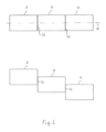
- Fig.2 1 shows two different arrangements of the three containers 9, 10, 11 in a schematic plan view.
- the containers 9, 10, 11 are arranged in a row along an axis A and are welded to one another on their sides by weld seams 32.
- the three containers 9, 10, 11 are offset from one another and arranged side by side.
- the small sewage treatment plant can be supplemented with another tank for water.
- the containers 9, 10, 11 can have different volumes.
- the small wastewater treatment plant with an additional rainwater tank is preferably located below ground level. However, it can also be arranged above the ground and uses the technical advantages offered by the rigid connection of the various containers to one another.
Landscapes
- Life Sciences & Earth Sciences (AREA)
- Biodiversity & Conservation Biology (AREA)
- Microbiology (AREA)
- Hydrology & Water Resources (AREA)
- Engineering & Computer Science (AREA)
- Environmental & Geological Engineering (AREA)
- Water Supply & Treatment (AREA)
- Chemical & Material Sciences (AREA)
- Organic Chemistry (AREA)
- Sewage (AREA)
Applications Claiming Priority (1)
| Application Number | Priority Date | Filing Date | Title |
|---|---|---|---|
| DE202021105490.5U DE202021105490U1 (de) | 2021-10-11 | 2021-10-11 | Kleinkläranlage mit zusätzlichem Wasserbehälter |
Publications (2)
| Publication Number | Publication Date |
|---|---|
| EP4163260A1 true EP4163260A1 (fr) | 2023-04-12 |
| EP4163260B1 EP4163260B1 (fr) | 2026-01-28 |
Family
ID=78605501
Family Applications (1)
| Application Number | Title | Priority Date | Filing Date |
|---|---|---|---|
| EP22200709.8A Active EP4163260B1 (fr) | 2021-10-11 | 2022-10-11 | Petite station d'epuration enterré avec reservoir d'eau supplementaire |
Country Status (2)
| Country | Link |
|---|---|
| EP (1) | EP4163260B1 (fr) |
| DE (1) | DE202021105490U1 (fr) |
Citations (5)
| Publication number | Priority date | Publication date | Assignee | Title |
|---|---|---|---|---|
| US3933641A (en) | 1974-03-04 | 1976-01-20 | Environs Engineering Enterprises, Inc. | Sewage treatment and recycling system |
| US20060283795A1 (en) * | 2001-04-13 | 2006-12-21 | Nurse Harry L Jr | System And Method For Treating Wastewater Using Coir Filter |
| JP2015148434A (ja) * | 2014-01-09 | 2015-08-20 | 林 徹 | 地下水利用システム |
| US20160376177A1 (en) * | 2015-06-24 | 2016-12-29 | Pallette Stone Corporation | Underground Septic Tank |
| EP3636405A1 (fr) * | 2018-10-09 | 2020-04-15 | Eloy Water Group | Réservoir de traitement des eaux usées rotomoulé et son procédé de fabrication |
-
2021
- 2021-10-11 DE DE202021105490.5U patent/DE202021105490U1/de active Active
-
2022
- 2022-10-11 EP EP22200709.8A patent/EP4163260B1/fr active Active
Patent Citations (5)
| Publication number | Priority date | Publication date | Assignee | Title |
|---|---|---|---|---|
| US3933641A (en) | 1974-03-04 | 1976-01-20 | Environs Engineering Enterprises, Inc. | Sewage treatment and recycling system |
| US20060283795A1 (en) * | 2001-04-13 | 2006-12-21 | Nurse Harry L Jr | System And Method For Treating Wastewater Using Coir Filter |
| JP2015148434A (ja) * | 2014-01-09 | 2015-08-20 | 林 徹 | 地下水利用システム |
| US20160376177A1 (en) * | 2015-06-24 | 2016-12-29 | Pallette Stone Corporation | Underground Septic Tank |
| EP3636405A1 (fr) * | 2018-10-09 | 2020-04-15 | Eloy Water Group | Réservoir de traitement des eaux usées rotomoulé et son procédé de fabrication |
Also Published As
| Publication number | Publication date |
|---|---|
| EP4163260B1 (fr) | 2026-01-28 |
| DE202021105490U1 (de) | 2021-10-28 |
Similar Documents
| Publication | Publication Date | Title |
|---|---|---|
| EP2085527B1 (fr) | Installation d'exploitation d'eau de pluie | |
| DE202009010367U1 (de) | Vorrichtung zur Trennung von Regenwasser von chemisch, biologisch und/oder toxisch belasteten Abwässern | |
| EP2659944B1 (fr) | Agencement de filtration et procédé d'intégration de l'agencement de filtration | |
| DE102007012266A1 (de) | Filtervorrichtung für ein Reinigungssystem für mit Feststoffpartikeln und/oder gelösten Schadstoffen belastetes Wasser | |
| EP0699255B1 (fr) | Construction prefabriquee en beton arme ou dans un materiau equivalent | |
| EP1919833B1 (fr) | Dispositif d'epuration des eaux usees | |
| EP4163260A1 (fr) | Petite station d'epuration enterré avec reservoir d'eau supplementaire | |
| WO2015055749A1 (fr) | Procédé de construction d'une installation de relevage d'eaux usées dans un puits d'égout et installation de relevage d'eaux usées correspondante | |
| DE202008011014U1 (de) | Verbesserter Straßen- oder Bodeneinlauf mit Rückhalteeinrichtung für Leichtflüssigkeiten | |
| EP0767278A1 (fr) | Système de caniveau pour l'infiltration d'eau | |
| DE19509466A1 (de) | Speicher für Flüssigkeiten | |
| DE3518840C2 (fr) | ||
| DE29618763U1 (de) | Anlage zur Entsorgung von Klärschlamm | |
| AT527034B1 (de) | Auslaufbehälter, System und Verfahren zur Oberflächenentwässerung | |
| DE19714739A1 (de) | Regenwasserspeicher | |
| DE202009001934U1 (de) | Kunststoffbehälter | |
| DE10004063C1 (de) | Deponie für ein Material mit einem hohen Feuchtigkeitsgehalt sowie Verfahren zum Betreiben einer Deponie | |
| EP1245537A2 (fr) | Station d'épuration d' eau polluée avec une couche à plantes | |
| DE102024122143B3 (de) | Schwimmteichsystem | |
| EP0679209B1 (fr) | Reservoir | |
| CH703152B1 (de) | Filteranlage. | |
| AT501959B1 (de) | Teichanlage | |
| DE4204635A1 (de) | Regenwasserentlastungseinrichtung, insbesondere zur verwendung im nichtindustriellen bereich | |
| DE20005108U1 (de) | Transportable biologische Pflanzenkläranlage, eingebaut in Norm Container | |
| DE10307057B4 (de) | Transportabler Behälter zum Filtern von Schmutzwasser |
Legal Events
| Date | Code | Title | Description |
|---|---|---|---|
| PUAI | Public reference made under article 153(3) epc to a published international application that has entered the european phase |
Free format text: ORIGINAL CODE: 0009012 |
|
| STAA | Information on the status of an ep patent application or granted ep patent |
Free format text: STATUS: THE APPLICATION HAS BEEN PUBLISHED |
|
| AK | Designated contracting states |
Kind code of ref document: A1 Designated state(s): AL AT BE BG CH CY CZ DE DK EE ES FI FR GB GR HR HU IE IS IT LI LT LU LV MC ME MK MT NL NO PL PT RO RS SE SI SK SM TR |
|
| STAA | Information on the status of an ep patent application or granted ep patent |
Free format text: STATUS: REQUEST FOR EXAMINATION WAS MADE |
|
| 17P | Request for examination filed |
Effective date: 20230710 |
|
| RBV | Designated contracting states (corrected) |
Designated state(s): AL AT BE BG CH CY CZ DE DK EE ES FI FR GB GR HR HU IE IS IT LI LT LU LV MC ME MK MT NL NO PL PT RO RS SE SI SK SM TR |
|
| GRAP | Despatch of communication of intention to grant a patent |
Free format text: ORIGINAL CODE: EPIDOSNIGR1 |
|
| STAA | Information on the status of an ep patent application or granted ep patent |
Free format text: STATUS: GRANT OF PATENT IS INTENDED |
|
| RIC1 | Information provided on ipc code assigned before grant |
Ipc: C02F 3/04 20230101AFI20250820BHEP Ipc: C02F 3/06 20230101ALN20250820BHEP Ipc: C02F 3/12 20230101ALN20250820BHEP |
|
| INTG | Intention to grant announced |
Effective date: 20250915 |
|
| GRAS | Grant fee paid |
Free format text: ORIGINAL CODE: EPIDOSNIGR3 |
|
| GRAA | (expected) grant |
Free format text: ORIGINAL CODE: 0009210 |
|
| STAA | Information on the status of an ep patent application or granted ep patent |
Free format text: STATUS: THE PATENT HAS BEEN GRANTED |
|
| AK | Designated contracting states |
Kind code of ref document: B1 Designated state(s): AL AT BE BG CH CY CZ DE DK EE ES FI FR GB GR HR HU IE IS IT LI LT LU LV MC ME MK MT NL NO PL PT RO RS SE SI SK SM TR |
|
| REG | Reference to a national code |
Ref country code: CH Ref legal event code: F10 Free format text: ST27 STATUS EVENT CODE: U-0-0-F10-F00 (AS PROVIDED BY THE NATIONAL OFFICE) Effective date: 20260128 Ref country code: GB Ref legal event code: FG4D Free format text: NOT ENGLISH |
|
| REG | Reference to a national code |
Ref country code: DE Ref legal event code: R096 Ref document number: 502022006871 Country of ref document: DE |
|
| REG | Reference to a national code |
Ref country code: IE Ref legal event code: FG4D Free format text: LANGUAGE OF EP DOCUMENT: GERMAN |