EP4163361A1 - Instrument de traitement monocéllulaire - Google Patents
Instrument de traitement monocéllulaire Download PDFInfo
- Publication number
- EP4163361A1 EP4163361A1 EP20939603.5A EP20939603A EP4163361A1 EP 4163361 A1 EP4163361 A1 EP 4163361A1 EP 20939603 A EP20939603 A EP 20939603A EP 4163361 A1 EP4163361 A1 EP 4163361A1
- Authority
- EP
- European Patent Office
- Prior art keywords
- boss
- connects
- microchannel
- air flow
- upper cover
- Prior art date
- Legal status (The legal status is an assumption and is not a legal conclusion. Google has not performed a legal analysis and makes no representation as to the accuracy of the status listed.)
- Pending
Links
Images




Classifications
-
- C—CHEMISTRY; METALLURGY
- C12—BIOCHEMISTRY; BEER; SPIRITS; WINE; VINEGAR; MICROBIOLOGY; ENZYMOLOGY; MUTATION OR GENETIC ENGINEERING
- C12N—MICROORGANISMS OR ENZYMES; COMPOSITIONS THEREOF; PROPAGATING, PRESERVING, OR MAINTAINING MICROORGANISMS; MUTATION OR GENETIC ENGINEERING; CULTURE MEDIA
- C12N15/00—Mutation or genetic engineering; DNA or RNA concerning genetic engineering, vectors, e.g. plasmids, or their isolation, preparation or purification; Use of hosts therefor
- C12N15/09—Recombinant DNA-technology
- C12N15/10—Processes for the isolation, preparation or purification of DNA or RNA
- C12N15/1003—Extracting or separating nucleic acids from biological samples, e.g. pure separation or isolation methods; Conditions, buffers or apparatuses therefor
- C12N15/1006—Extracting or separating nucleic acids from biological samples, e.g. pure separation or isolation methods; Conditions, buffers or apparatuses therefor by means of a solid support carrier, e.g. particles, polymers
- C12N15/1013—Extracting or separating nucleic acids from biological samples, e.g. pure separation or isolation methods; Conditions, buffers or apparatuses therefor by means of a solid support carrier, e.g. particles, polymers by using magnetic beads
-
- C—CHEMISTRY; METALLURGY
- C12—BIOCHEMISTRY; BEER; SPIRITS; WINE; VINEGAR; MICROBIOLOGY; ENZYMOLOGY; MUTATION OR GENETIC ENGINEERING
- C12M—APPARATUS FOR ENZYMOLOGY OR MICROBIOLOGY; APPARATUS FOR CULTURING MICROORGANISMS FOR PRODUCING BIOMASS, FOR GROWING CELLS OR FOR OBTAINING FERMENTATION OR METABOLIC PRODUCTS, i.e. BIOREACTORS OR FERMENTERS
- C12M23/00—Constructional details, e.g. recesses, hinges
- C12M23/42—Integrated assemblies, e.g. cassettes or cartridges
-
- B—PERFORMING OPERATIONS; TRANSPORTING
- B01—PHYSICAL OR CHEMICAL PROCESSES OR APPARATUS IN GENERAL
- B01L—CHEMICAL OR PHYSICAL LABORATORY APPARATUS FOR GENERAL USE
- B01L3/00—Containers or dishes for laboratory use, e.g. laboratory glassware; Droppers
- B01L3/50—Containers for the purpose of retaining a material to be analysed, e.g. test tubes
- B01L3/502—Containers for the purpose of retaining a material to be analysed, e.g. test tubes with fluid transport, e.g. in multi-compartment structures
- B01L3/5027—Containers for the purpose of retaining a material to be analysed, e.g. test tubes with fluid transport, e.g. in multi-compartment structures by integrated microfluidic structures, i.e. dimensions of channels and chambers are such that surface tension forces are important, e.g. lab-on-a-chip
- B01L3/502715—Containers for the purpose of retaining a material to be analysed, e.g. test tubes with fluid transport, e.g. in multi-compartment structures by integrated microfluidic structures, i.e. dimensions of channels and chambers are such that surface tension forces are important, e.g. lab-on-a-chip characterised by interfacing components, e.g. fluidic, electrical, optical or mechanical interfaces
-
- B—PERFORMING OPERATIONS; TRANSPORTING
- B01—PHYSICAL OR CHEMICAL PROCESSES OR APPARATUS IN GENERAL
- B01L—CHEMICAL OR PHYSICAL LABORATORY APPARATUS FOR GENERAL USE
- B01L3/00—Containers or dishes for laboratory use, e.g. laboratory glassware; Droppers
- B01L3/50—Containers for the purpose of retaining a material to be analysed, e.g. test tubes
- B01L3/502—Containers for the purpose of retaining a material to be analysed, e.g. test tubes with fluid transport, e.g. in multi-compartment structures
- B01L3/5027—Containers for the purpose of retaining a material to be analysed, e.g. test tubes with fluid transport, e.g. in multi-compartment structures by integrated microfluidic structures, i.e. dimensions of channels and chambers are such that surface tension forces are important, e.g. lab-on-a-chip
- B01L3/502761—Containers for the purpose of retaining a material to be analysed, e.g. test tubes with fluid transport, e.g. in multi-compartment structures by integrated microfluidic structures, i.e. dimensions of channels and chambers are such that surface tension forces are important, e.g. lab-on-a-chip specially adapted for handling suspended solids or molecules independently from the bulk fluid flow, e.g. for trapping or sorting beads or physically stretching molecules
-
- B—PERFORMING OPERATIONS; TRANSPORTING
- B01—PHYSICAL OR CHEMICAL PROCESSES OR APPARATUS IN GENERAL
- B01L—CHEMICAL OR PHYSICAL LABORATORY APPARATUS FOR GENERAL USE
- B01L9/00—Supporting devices; Holding devices
- B01L9/52—Supports specially adapted for flat sample carriers, e.g. for plates, slides, chips
- B01L9/527—Supports specially adapted for flat sample carriers, e.g. for plates, slides, chips for microfluidic devices, e.g. used for lab-on-a-chip
-
- C—CHEMISTRY; METALLURGY
- C12—BIOCHEMISTRY; BEER; SPIRITS; WINE; VINEGAR; MICROBIOLOGY; ENZYMOLOGY; MUTATION OR GENETIC ENGINEERING
- C12M—APPARATUS FOR ENZYMOLOGY OR MICROBIOLOGY; APPARATUS FOR CULTURING MICROORGANISMS FOR PRODUCING BIOMASS, FOR GROWING CELLS OR FOR OBTAINING FERMENTATION OR METABOLIC PRODUCTS, i.e. BIOREACTORS OR FERMENTERS
- C12M23/00—Constructional details, e.g. recesses, hinges
- C12M23/02—Form or structure of the vessel
- C12M23/16—Microfluidic devices; Capillary tubes
-
- C—CHEMISTRY; METALLURGY
- C12—BIOCHEMISTRY; BEER; SPIRITS; WINE; VINEGAR; MICROBIOLOGY; ENZYMOLOGY; MUTATION OR GENETIC ENGINEERING
- C12M—APPARATUS FOR ENZYMOLOGY OR MICROBIOLOGY; APPARATUS FOR CULTURING MICROORGANISMS FOR PRODUCING BIOMASS, FOR GROWING CELLS OR FOR OBTAINING FERMENTATION OR METABOLIC PRODUCTS, i.e. BIOREACTORS OR FERMENTERS
- C12M47/00—Means for after-treatment of the produced biomass or of the fermentation or metabolic products, e.g. storage of biomass
- C12M47/04—Cell isolation or sorting
-
- C—CHEMISTRY; METALLURGY
- C12—BIOCHEMISTRY; BEER; SPIRITS; WINE; VINEGAR; MICROBIOLOGY; ENZYMOLOGY; MUTATION OR GENETIC ENGINEERING
- C12M—APPARATUS FOR ENZYMOLOGY OR MICROBIOLOGY; APPARATUS FOR CULTURING MICROORGANISMS FOR PRODUCING BIOMASS, FOR GROWING CELLS OR FOR OBTAINING FERMENTATION OR METABOLIC PRODUCTS, i.e. BIOREACTORS OR FERMENTERS
- C12M47/00—Means for after-treatment of the produced biomass or of the fermentation or metabolic products, e.g. storage of biomass
- C12M47/06—Hydrolysis; Cell lysis; Extraction of intracellular or cell wall material
-
- G—PHYSICS
- G01—MEASURING; TESTING
- G01N—INVESTIGATING OR ANALYSING MATERIALS BY DETERMINING THEIR CHEMICAL OR PHYSICAL PROPERTIES
- G01N35/00—Automatic analysis not limited to methods or materials provided for in any single one of groups G01N1/00 - G01N33/00; Handling materials therefor
- G01N35/10—Devices for transferring samples or any liquids to, in, or from, the analysis apparatus, e.g. suction devices, injection devices
- G01N35/1065—Multiple transfer devices
-
- B—PERFORMING OPERATIONS; TRANSPORTING
- B01—PHYSICAL OR CHEMICAL PROCESSES OR APPARATUS IN GENERAL
- B01L—CHEMICAL OR PHYSICAL LABORATORY APPARATUS FOR GENERAL USE
- B01L2200/00—Solutions for specific problems relating to chemical or physical laboratory apparatus
- B01L2200/06—Fluid handling related problems
- B01L2200/0647—Handling flowable solids, e.g. microscopic beads, cells, particles
-
- B—PERFORMING OPERATIONS; TRANSPORTING
- B01—PHYSICAL OR CHEMICAL PROCESSES OR APPARATUS IN GENERAL
- B01L—CHEMICAL OR PHYSICAL LABORATORY APPARATUS FOR GENERAL USE
- B01L2200/00—Solutions for specific problems relating to chemical or physical laboratory apparatus
- B01L2200/06—Fluid handling related problems
- B01L2200/0647—Handling flowable solids, e.g. microscopic beads, cells, particles
- B01L2200/0668—Trapping microscopic beads
-
- B—PERFORMING OPERATIONS; TRANSPORTING
- B01—PHYSICAL OR CHEMICAL PROCESSES OR APPARATUS IN GENERAL
- B01L—CHEMICAL OR PHYSICAL LABORATORY APPARATUS FOR GENERAL USE
- B01L2200/00—Solutions for specific problems relating to chemical or physical laboratory apparatus
- B01L2200/14—Process control and prevention of errors
- B01L2200/143—Quality control, feedback systems
- B01L2200/146—Employing pressure sensors
-
- B—PERFORMING OPERATIONS; TRANSPORTING
- B01—PHYSICAL OR CHEMICAL PROCESSES OR APPARATUS IN GENERAL
- B01L—CHEMICAL OR PHYSICAL LABORATORY APPARATUS FOR GENERAL USE
- B01L2200/00—Solutions for specific problems relating to chemical or physical laboratory apparatus
- B01L2200/14—Process control and prevention of errors
- B01L2200/143—Quality control, feedback systems
- B01L2200/147—Employing temperature sensors
-
- B—PERFORMING OPERATIONS; TRANSPORTING
- B01—PHYSICAL OR CHEMICAL PROCESSES OR APPARATUS IN GENERAL
- B01L—CHEMICAL OR PHYSICAL LABORATORY APPARATUS FOR GENERAL USE
- B01L2200/00—Solutions for specific problems relating to chemical or physical laboratory apparatus
- B01L2200/16—Reagents, handling or storing thereof
-
- B—PERFORMING OPERATIONS; TRANSPORTING
- B01—PHYSICAL OR CHEMICAL PROCESSES OR APPARATUS IN GENERAL
- B01L—CHEMICAL OR PHYSICAL LABORATORY APPARATUS FOR GENERAL USE
- B01L2300/00—Additional constructional details
- B01L2300/08—Geometry, shape and general structure
- B01L2300/0861—Configuration of multiple channels and/or chambers in a single devices
-
- B—PERFORMING OPERATIONS; TRANSPORTING
- B01—PHYSICAL OR CHEMICAL PROCESSES OR APPARATUS IN GENERAL
- B01L—CHEMICAL OR PHYSICAL LABORATORY APPARATUS FOR GENERAL USE
- B01L2300/00—Additional constructional details
- B01L2300/18—Means for temperature control
- B01L2300/1805—Conductive heating, heat from thermostatted solids is conducted to receptacles, e.g. heating plates, blocks
-
- B—PERFORMING OPERATIONS; TRANSPORTING
- B01—PHYSICAL OR CHEMICAL PROCESSES OR APPARATUS IN GENERAL
- B01L—CHEMICAL OR PHYSICAL LABORATORY APPARATUS FOR GENERAL USE
- B01L2400/00—Moving or stopping fluids
- B01L2400/04—Moving fluids with specific forces or mechanical means
- B01L2400/0403—Moving fluids with specific forces or mechanical means specific forces
- B01L2400/043—Moving fluids with specific forces or mechanical means specific forces magnetic forces
-
- B—PERFORMING OPERATIONS; TRANSPORTING
- B01—PHYSICAL OR CHEMICAL PROCESSES OR APPARATUS IN GENERAL
- B01L—CHEMICAL OR PHYSICAL LABORATORY APPARATUS FOR GENERAL USE
- B01L2400/00—Moving or stopping fluids
- B01L2400/06—Valves, specific forms thereof
- B01L2400/0622—Valves, specific forms thereof distribution valves, valves having multiple inlets and/or outlets, e.g. metering valves, multi-way valves
Definitions
- the present application relates to the field of single cell analysis technique, for example, an instrument for high throughput single cell processing.
- the deoxyribonucleic acid (DNA) or ribonucleic acid (RNA) extraction from a single cell is mainly operated in a semi-automatic way, which is complicated, taking longer operation time with poorer accuracy of the experiment results. Moreover, it is often difficult to process thousands of single cells in parallel.
- This application discloses a single cell processing instrument.
- the instrument can separate single cells, label each single cell, and extract DNA or RNA from each single cell.
- the instrument is easy to operate and provides high-accuracy experimental results.
- the instrument comprises a motor component, a processing component, a container, a chip, a snap component, and a pneumatic component.
- the processing component comprises a processing chamber and multiple first connecting holes.
- the container locates inside the processing chamber and comprises a sample collecting reservoir, a waste collecting reservoir, multiple sample loading reservoirs, multiple first microchannels, and a second microchannel. A first end of each sample loading reservoir connects with one first connecting hole. A second end of each sample loading reservoir connects with one first microchannel. A first end of the sample collecting reservoir and a first end of the waste collecting reservoir each connects with one first connecting hole. A second end of the sample collecting reservoir and a second end of the waste collecting reservoir both connect with the second microchannel.
- the chip locates under the container.
- a snap gap is formed between the chip and the middle portion of the container.
- the chip comprises a third microchannel.
- the bottom of the third microchannel comprises a microwell array.
- the third microchannel comprises an inlet and an outlet.
- the inlet of the third microchannel connects with the first microchannels.
- a gap is formed between the inlet of the third microchannel and the container.
- the outlet of the third microchannel connects with the sample collecting reservoir and the waste collecting revoir through the second microchannel.
- the snap component comprises a feeding beam and a snap body.
- a first end of the feeding beam connects with the snap body.
- a second end of the feeding beam connects with the motor component.
- the feeding beam is configured to be driven by the motor component to insert the snap body into the snap gap to lift magnetic beads with samples from the bottom of the third microchannel.
- the pneumatic component connects with multiple first connecting holes and is configured to control air flow to each first connecting hole.
- the instrument comprises a motor component 1, a processing component 2, a container 31, a chip 41, a snap component 5, and a pneumatic component.
- the processing component 2 comprises a processing chamber inside which the container 31 is located. In one embodiment, two processing chambers locate inside the processing component, and the two processing chambers connect to each other; and two containers 31 locate inside the two processing chambers with one container 31 locates in one processing chamber.
- the single cell processing instrument can have two samples running in parallel so that the experiment speed is greatly improved.
- the number of processing chambers may also be one, three, or others, depending on the actual conditions.
- the processing component 2 comprises twenty first connecting holes 20. The twenty first connecting holes 20 are equally divided into two first connecting hole groups, each having ten first connecting holes 20.
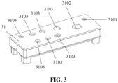
- the container 31 comprises a sample collecting reservoir 3101, a waste collecting reservoir 3102, seven sample loading reservoirs 3103, seven first microchannels 3104, and a second microchannel 3105.
- a first end of each sample loading reservoir 3103 connects with one first connecting hole 20.
- a second end of each sample loading reservoir 3103 connects with one first microchannel 3104.
- a first end of the sample collecting reservoir 3101 and a first end of the waste collecting reservoir 3102 each connects with one first connecting hole 20.
- a second end of the sample collecting reservoir 3101 and a second end of the waste collecting reservoir 3102 both connect with the second microchannel 3105.
- the chip 41 locates under the container 31. A gap is formed between the chip 41 and the container 31.
- the chip 41 comprises a third microchannel 410.
- a snap gap is formed between the chip 41 and the middle portion of the container 31.
- the bottom of the third microchannel 410 comprises a microwell array. After thousands of suspended single cells are loaded into the third microchannel 410, some cells precipitate into the microwell array after a certain period to isolate from each other. Cells that do not precipitate inside the microwell array are removed in a subsequent washing step.
- An inlet 4101 of the third microchannel 410 connects with the first microchannels 3104 through the inlet reservoir 420.
- a gap is formed between the inlet reservoir 420 and the container 31.
- An outlet 4102 of the third microchannel 410 connects with the sample collecting reservoir 3101 and the waste collecting reservoir 3102 through the second microchannel 3105 and the fourth boss 43.
- the snap component 5 comprises a feeding beam 51 and a snap body 52.
- a first end of the feeding beam 51 connects to the snap body 52.
- a second end of the feeding beam 51 connects to the motor component 1.
- the feeding beam 51 is configured to be driven by the motor component 1 to insert the snap body 52 into the snap gap to lift the magnetic beads with samples from the bottom of the third microchannel 410. In this manner, the samples are suspended in the third microchannel 410.
- the motor component 1 in this embodiment is a stepper motor.
- the pneumatic component connects with nine first connecting holes 20 of each first connecting hole group.
- the remaining one first connecting hole 20 in each first connecting hole group is left unconnected as a backup.
- the pneumatic component can control the on and off, and the pressure of the air flow to each first connecting hole 20.
- the number of the first connecting holes 20, the number of the sample loading reservoirs 3103, and the number of the first microchannels 3104 on the processing component 2 are not limited to the number described in this embodiment and may be other numbers, depending on the actual conditions.
- the single cell processing instrument can automatically process thousands of single cells in parallel, label each cell, and then extract DNAs or RNAs from the single cells.
- An operator loads a cell suspension, various reagents, and a magnetic bead suspension with molecular tags, into different sample loading reservoirs 3103.
- the pneumatic component controls the on and off, and the pressure of the air flow to each first connecting hole 20 so that the cell suspension, the magnetic bead suspension, a first reagent, a second reagent, a third reagent, and the like flow into the third microchannel 410 of the chip 41 sequentially to react with the cells and extract the desirable samples from the cells to bind to the magnetic beads.
- the desirable sample is the DNAs or RNAs of the single cells.
- the magnetic beads with extracted samples are lifted from the bottom of the third microchannel 410 so that the magnetic beads with extracted samples are suspended at the upper portion of the third microchannel 410.
- the magnetic beads with extracted samples are pushed to the outlet 4102 of the third microchannel 410 by the fluid flow and then are collected to the sample collecting reservoir 3101 through the second microchannel 3105.
- the solvents and the solutions after each reaction in the previous steps are collected into the waste collecting reservoir 3102. After sample collection, the experiment ends.
- the experimental process is automated, and the accuracy and the repeatability of the experimental results are higher than manual operation.
- the container 31 and the chip 41 are disposable, it reduces the cross-contamination between different samples. It also reduces the risk of cross-contamination from different samples introduced from the cleaning process of pipes inside an instrument.
- the pneumatic component comprises an air pump 61, nine solenoid valves 62, and a solenoid-valve control board 63.
- the solenoid-valve control board 63 is electrically connected to the nine solenoid valves 62.
- Each solenoid valve 62 relates to one first connecting hole 20 which connects with the container 31.
- the solenoid-valve control board 63 controls the on and off of the solenoid valves 62 to make the air pump 61 connect with or disconnect from the first connecting holes 20.
- the solenoid valves 62 When the solenoid valves 62 are turned on, the solenoid valves 62 are open so that the air pump 61 connects with the first connecting holes 20 and so that the air pump 61 can push air into the container 31 via positive pressure or suck air or liquid from the container 31 via negative pressure. When the solenoid valves 62 are turned off, the solenoid valves 62 are closed so that the air pump 61 is disconnected from the first connecting holes 20 and so that the air pump 61 cannot push air into the container 31 via positive pressure or suck air or liquid from the container 31 via negative pressure.
- the air pump 61 can push air into the container 31 through the first connecting holes 20 to increase the pressure inside the reservoir, and can suck air from the container 31 through the first connecting holes 20 to reduce the pressure inside the reservoir, and can automatically and accurately control the pushing and sucking air volume to precisely adjust the pressure inside the sample loading reservoirs 3103, the sample collecting reservoir 3101, and/or the waste collecting reservoir 3102 in the container 31, thereby increasing the accuracy of the experiment.
- the number of the solenoid valves 62 is not limited to nine as shown in this embodiment and may be other numbers. Moreover, the number of solenoid valves 62 is not less than the total number of the sample collecting reservoir 3101, the waste collecting reservoir 3102, and the sample loading reservoirs 3103.
- the pneumatic component comprises multiple connecting tubes (not shown). A first end of the connecting tube connects with the air pump 61. A second end of the connecting tube connects with the first connecting hole 20. Each connecting tube relates to one first connecting hole 20.
- a solenoid valve 62 is installed on the connecting tube. The solenoid valve 62 controls the connection of the air pump 61 to the connecting tube.
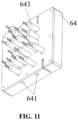
- the pneumatic component comprises an integrated air flow control board 64 and a control circuit board. As shown in FIGS. 10 and 11 , the integrated air flow control board 64 comprises air inlet holes 641, multiple air flow channels 642, and multiple air flow control valves 643. The air flow control valves 643 electrically connect to the control circuit board. The air inlet holes 641 connect with the air pump 61.
- a first end of the air flow channel 642 connects with the air inlet hole 641.
- a second end of the air flow channel 642 connects with the first connecting hole 20.
- An air flow control valve 643 integrates with one air flow channel 642 to control the continuity of the air flow in the air flow channel 642.
- Each air flow channel 642 relates to one first connecting hole 20.
- Each air flow control valve 643 relates to one first connecting holes 20.
- the control circuit board can individually control the on or off of each air flow control valve 643 to make the air pump 61 connect with or disconnect from the first connecting hole 20.
- the container 31 comprises four legs 34 to facilitate the container 31 positioning in the processing chamber, as shown in FIG. 4 .
- the four legs 34 locate at the four corners of the container 31 to support the container 31.
- a first end of the bottom of the container 31 comprises a first boss 32
- the first boss 32 comprises an exhaust hole 320.
- the exhaust hole 320 connects with the first microchannels 3104.
- the chip 41 comprises a second boss 42 corresponding to the first boss 32.
- the second boss 42 comprises an inlet reservoir 420 and a first through hole.
- the third microchannel 410 connects with the inlet reservoirs 420 through the first through hole.
- An exhaust gap is formed between the first boss 32 and the second boss 42.
- the second boss 42 is mounted inside the first boss 32 by a wall of the second boss 42 enclosed by a wall of the first boss 32 so that the reagents flowing out of the first microchannels 3104 can enter the third microchannel 410 through the inlet reservoir 420. Since the first microchannel 3104 connects with the inlet reservoir 420, as the reagent in the first microchannel 3104 flows out, the air pressure in the first microchannel 3104 is higher than the pressure in the processing chamber outside the container 31. In this manner, any air bubbles existed in the reagent can be released from the exhaust gap between the first boss 32 and the second boss 42, that is, no bubbles exist in the reagent entering the third microchannel 410.
- a second end of the bottom of the container 31 comprises a third boss 33.
- the third boss 33 comprises a mounting hole 330.
- the mounting hole 330 connects with the second microchannel 3105.
- a fourth boss 43 locates on the chip 41 and corresponds to the third boss 33.
- the fourth boss comprises a second through hole 430.
- the second through hole 430 connects with the third microchannel 410.
- the fourth boss 43 is under the third boss 33.
- the third boss 33 connects to the fourth boss 43 airtightly.
- a sealing ring locates between the third boss 33 and the fourth boss 43, ensuring that the second microchannel 3105 airtightly connects with the third microchannel 410, so that the waste and the sample from the third microchannel 410 can be collected to the waste collecting reservoir and the sample collecting reservoir respectively.
- the disclosed single cell processing instrument also comprises a sealing gasket 71, as shown in Fig. 6 , to ensure an airtight sealing between the first connecting holes 20 and the container 31.
- the sealing gasket 71 is a removable rubber sealing gasket.
- the sealing gasket 71 comprises nine second connecting holes 710. Each second connecting hole 710 relates to one first connecting hole 20. A first end of the second connecting hole 710 connects with one of the first connecting holes 20. A second end of the second connecting hole 710 connects with one of the sample loading reservoirs 3103, or the waste collecting reservoir 3102, or the sample collecting reservoir 3101.
- a sealing boss 72 locates on the periphery of each second connecting hole 710.
- the sealing boss 72 ensures an airtight sealing of the sealing gasket 71 with the sample loading reservoirs 3103, the waste collecting reservoir 3102, and the sample collecting reservoir 3101.
- the sealing gasket 71 comprises six tenons 73.
- the processing component 2 comprises twelve mounting blind holes 210.
- the twelve mounting blind holes 210 are equally divided into two mounting blind hole groups.
- the mounting blind holes 210 in each mounting blind hole group locate around the periphery of the first connecting holes 20 in one first connecting hole group.
- the tenons 73 mount with the mounting blind holes 210 with an interference fit to fix the sealing gasket 71 to the processing component 2.
- Each one of the six tenons 73 of the sealing gasket 71 relates to one of the six mounting blind holes 210 in one mounting blind hole group.
- the number of second connecting holes 710 is not limited to nine and may be other numbers, depending on the total number of sample collecting reservoir 3101, waste collecting reservoir 3102, and sample loading reservoirs 3103.
- the number of second connecting holes 710 is eleven, and the number of sealing bosses 72 is eleven; thus the corresponding total number of sample collecting reservoir 3101, waste collecting reservoir 3102, and sample loading reservoirs 3103 should be eleven.
- the sealing gasket 71 might be detachably mounted to the container 31 by the tenons in an interference fit. In one embodiment, the sealing gasket 71 might be fixed onto the processing component 2. In one embodiment, the sealing gasket 71 might be fixed onto the container 31. In other embodiments, the sealing gasket 71 might be sandwiched between the processing component 2 and the container 31 to provide an airtight sealing between the processing component 2 and the container 31. In other embodiments, the sealing boss 72 might locate on a side of the container 31 facing the sealing gasket 71, or on a side of the sealing gasket 71 facing the container 31, or on two sides of the sealing gasket 71 so that the container 31 is airtightly sealed to the processing component 2.
- the processing component 2 comprises an upper cover 21 and a processing component body 22.
- the upper cover 21 comprises the first connecting holes 20.
- a first end of the upper cover 21 connects with a first end of the processing component body 22 with rotatable connection.
- a second end of the upper cover 21 is tightly sealed with the processing component body 22 so that the processing chamber is formed by the upper cover and the processing component body 22.
- the upper cover 21 and the processing component body 22 are magnetically connected with a snap fit.
- the upper cover 21 comprises a protrusion (not shown).
- the processing component body 22 comprises a lock notch 220 corresponding to the protrusion.
- the upper cover 21 comprises a first magnet.
- the processing component body 22 comprises a second magnet 23 corresponding to the first magnet.
- the first magnet attracts the second magnet 23 so that the upper cover 21 is tightly sealed with the processing component body 22.
- the electromagnetic attraction force between the upper cover 21 and the processing component body 22 increases, resulting in the sealing of the upper cover 21 and the processing component body 22. In this manner, it reduces the risk of opening the upper cover accidently during the operation of the single cell processing instrument, which introduces a failure of the experiment.
- the processing component body 22 comprises a protrusion
- the upper cover 21 comprises a lock notch 220 corresponding to the protrusion.
- the upper cover 21 might be snap fit to but not magnetically connect to the processing component body 22.
- the upper cover 21 might be magnetically connect to but not snap fit to the processing component body 22.
- the upper cover 21 might locate above the processing component body 22, and the upper cover 21 might slide relatively to the processing component body 22 so that the upper cover 21 can tightly seal to the processing component body 22 to form a processing chamber. That is, when the processing component 2 is closing, the upper cover 21 moves toward the processing component body 22 to seal to the processing component body 22; and when the processing component 2 is opening, the upper cover 21 moves away from the processing component body 22 to detach from the processing component body 22.
- the processing component body 22 further comprises an insulation wall 221, a heating stage 222, and a cooling fan (not shown).
- the insulation wall 221 locates around the periphery of the heating stage 222.
- the upper cover 21, the insulation wall 221, and the heating stage 222 form the processing chamber.
- the cooling fan locates under the heating stage 222 to cool the heating stage 222.
- the heating stage 222 comprises a sample stage, a heating pad, and a temperature sensor.
- the sample stage stacks on the heating pad.
- the temperature sensor is configured to measure the temperature of the heating pad.
- a sample holder 2220 locates on the top of the sample stage.
- the sample holder 2220 holds the chip 41 and the container 31 with the chip 41 fitting inside the sample holder 2220.
- Each sample holder 2220 holds one chip 41.
- the insulation wall 221 locates around the periphery of the heating stage 222 to form a sealed insulation chamber for the heating stage 222. Heating and cooling reagents in the third microchannels 410 of the chip 41 are required during the experimental operation.
- the heating stage 222 and the insulation wall 221 enables rapid heating and temperature insulation of the samples inside the insulation chamber.
- the cooling fan enables the rapid temperature adjustment of the heating stage 222, the chip 41, and the samples inside the insulation chamber.
- the single cell processing instrument further comprises two pressure sensors 8.
- the two pressure sensors 8 locate under the cooling fan. One pressure sensor is used to measure the air pressure at the inlet of the air pump 61. The other pressure sensor is used to measure the air pressure at the outlet of the air pump 61.
- the single cell processing instrument further comprises a controller.
- the controller electrically connects to the motor component 1, the solenoid-valve control board 63, the air pump 61, the temperature sensor, the heating stage 222, the cooling fan, and the two pressure sensors 8.
- the controller might be in a centralized control model or in a distributed control model.
- the controller might be one independent microcontroller or multiple distributed microcontrollers.
- the microcontroller controls the motor component 1, the solenoid-valve control board 63, the air pump 61, the temperature sensor, the heating stage 222, the cooling fan, and the two pressure sensors 8.
- RNAs from single cells is described in the following:
- the chip 41 and the processing chamber 2 are heated or cooled by the temperature control system according to the temperature requirements of different reagents and the temperature requirements of the biochemical reactions.
- the process of heating the reagent in the chip 41 by the heating stage 222 and the process of cooling the reagent in the chip 41 by the cooling fan are not described in the above process.
- the appropriate temperature required for each step may be obtained by programming the controller.
- the temperature sensor measures the temperature of the heating pad in real time to monitor the temperature of the reagents.
- the cooling fan is always on to dissipate the heat from the chip 41 and the processing chamber.
- This embodiment shows only one exemplary of the operation of the single cell processing instrument. Other exemplary of the operation of the instrument is not excluded.
- the single cell processing instrument disclosed here is fully automatic, using less time in the whole experimental process, reducing the failure rate to extract the DNAs or RNAs from thousands of single cells in parallel compared to a manual operation. Therefore, it increases the success rate of the experiments, and improves the accuracy of the experimental results.
- the sealing gasket, the container, and the chip of the single cell processing instrument are disposable so that it reduces the risk of cross-contamination from different samples and the inadequate cleaning of the instrument pipes.
Landscapes
- Chemical & Material Sciences (AREA)
- Health & Medical Sciences (AREA)
- Life Sciences & Earth Sciences (AREA)
- Engineering & Computer Science (AREA)
- Wood Science & Technology (AREA)
- Organic Chemistry (AREA)
- Bioinformatics & Cheminformatics (AREA)
- Zoology (AREA)
- Genetics & Genomics (AREA)
- Biomedical Technology (AREA)
- Biotechnology (AREA)
- General Health & Medical Sciences (AREA)
- General Engineering & Computer Science (AREA)
- Biochemistry (AREA)
- Analytical Chemistry (AREA)
- Microbiology (AREA)
- Clinical Laboratory Science (AREA)
- Physics & Mathematics (AREA)
- Dispersion Chemistry (AREA)
- Molecular Biology (AREA)
- Sustainable Development (AREA)
- Chemical Kinetics & Catalysis (AREA)
- Crystallography & Structural Chemistry (AREA)
- Biophysics (AREA)
- Plant Pathology (AREA)
- Hematology (AREA)
- Cell Biology (AREA)
- Fluid Mechanics (AREA)
- General Physics & Mathematics (AREA)
- Immunology (AREA)
- Pathology (AREA)
- Apparatus Associated With Microorganisms And Enzymes (AREA)
- Automatic Analysis And Handling Materials Therefor (AREA)
Applications Claiming Priority (1)
| Application Number | Priority Date | Filing Date | Title |
|---|---|---|---|
| PCT/CN2020/095005 WO2021248291A1 (fr) | 2020-06-09 | 2020-06-09 | Instrument de traitement monocéllulaire |
Publications (2)
| Publication Number | Publication Date |
|---|---|
| EP4163361A1 true EP4163361A1 (fr) | 2023-04-12 |
| EP4163361A4 EP4163361A4 (fr) | 2024-03-06 |
Family
ID=78846649
Family Applications (1)
| Application Number | Title | Priority Date | Filing Date |
|---|---|---|---|
| EP20939603.5A Pending EP4163361A4 (fr) | 2020-06-09 | 2020-06-09 | Instrument de traitement monocéllulaire |
Country Status (4)
| Country | Link |
|---|---|
| US (1) | US20230212552A1 (fr) |
| EP (1) | EP4163361A4 (fr) |
| CN (1) | CN114222809B (fr) |
| WO (1) | WO2021248291A1 (fr) |
Families Citing this family (1)
| Publication number | Priority date | Publication date | Assignee | Title |
|---|---|---|---|---|
| CN118496966B (zh) * | 2024-06-20 | 2025-02-28 | 逐因生物科技(重庆)有限公司 | 供气组件、单细胞测序建库设备及其控制方法 |
Family Cites Families (16)
| Publication number | Priority date | Publication date | Assignee | Title |
|---|---|---|---|---|
| US8133671B2 (en) * | 2007-07-13 | 2012-03-13 | Handylab, Inc. | Integrated apparatus for performing nucleic acid extraction and diagnostic testing on multiple biological samples |
| CA3016967C (fr) * | 2010-04-16 | 2021-08-31 | Opko Diagnostics, Llc | Systemes et appareils d'analyse d'echantillons |
| KR20120063162A (ko) * | 2010-12-07 | 2012-06-15 | 삼성전자주식회사 | 유전자 분석 장치 및 이를 이용한 유전자 분석 방법 |
| RU2013148071A (ru) * | 2011-04-01 | 2015-05-10 | Президент Энд Феллоуз Ов Харвард Колледж | Аналогичное диализу терапевтическое (dlt) устройство |
| US9707562B2 (en) * | 2013-03-13 | 2017-07-18 | Denovo Sciences, Inc. | System for capturing and analyzing cells |
| US11203016B2 (en) * | 2015-12-01 | 2021-12-21 | Illumina, Inc. | Digital microfluidic system for single-cell isolation and characterization of analytes |
| US11300578B2 (en) * | 2016-09-19 | 2022-04-12 | Roche Molecular Systems, Inc. | Instrument for processing cartridge for performing assays in a closed sample preparation and reaction system |
| US11179723B2 (en) * | 2017-03-28 | 2021-11-23 | Redbud Labs, Inc. | System, fluidics cartridge, and methods for using actuated surface-attached posts for processing cells |
| CN109022274A (zh) * | 2017-06-08 | 2018-12-18 | 北京万泰生物药业股份有限公司 | 微流控芯片、芯片操纵系统、微流控装置和核酸提取方法 |
| US10391492B2 (en) * | 2017-08-29 | 2019-08-27 | Celsee Diagnostics, Inc. | System and method for isolating and analyzing cells |
| CN107715930B (zh) * | 2017-09-22 | 2020-03-17 | 华中科技大学同济医学院附属协和医院 | 芯片结构 |
| US11110457B2 (en) * | 2017-12-28 | 2021-09-07 | Stmicroelectronics S.R.L. | Analysis unit for a transportable microfluidic device, in particular for sample preparation and molecule analysis |
| CN110699432A (zh) * | 2018-07-10 | 2020-01-17 | Tdk株式会社 | 采用恒温扩增技术检测核酸的装置与方法 |
| CN209243044U (zh) * | 2018-11-06 | 2019-08-13 | 深圳华大生命科学研究院 | 微孔芯片及单细胞制备系统 |
| AU2020267743B2 (en) * | 2019-05-07 | 2023-04-06 | Bio-Rad Laboratories, Inc. | System and method for automated single cell processing |
| CN110373310B (zh) * | 2019-08-09 | 2020-09-22 | 上海烈冰生物医药科技有限公司 | 一种基于气动测控系统的微流控单细胞分选装置 |
-
2020
- 2020-06-09 WO PCT/CN2020/095005 patent/WO2021248291A1/fr not_active Ceased
- 2020-06-09 US US18/009,258 patent/US20230212552A1/en active Pending
- 2020-06-09 EP EP20939603.5A patent/EP4163361A4/fr active Pending
- 2020-06-09 CN CN202080036832.2A patent/CN114222809B/zh active Active
Also Published As
| Publication number | Publication date |
|---|---|
| US20230212552A1 (en) | 2023-07-06 |
| CN114222809A (zh) | 2022-03-22 |
| CN114222809B (zh) | 2024-10-11 |
| WO2021248291A1 (fr) | 2021-12-16 |
| EP4163361A4 (fr) | 2024-03-06 |
Similar Documents
| Publication | Publication Date | Title |
|---|---|---|
| US10434509B2 (en) | Apparatus for and method of processing biological samples | |
| CN216149780U (zh) | 体外诊断分析装置及试剂卡盒 | |
| US8921094B2 (en) | System and method for nucleic acids containing fluid processing | |
| EP2333559B1 (fr) | Procédé d'analyse d'acides nucléiques et analyseur automatique d'acides nucléiques avec séparation spatiale | |
| WO2013123035A1 (fr) | Système et procédé de traitement et détection d'acides nucléiques | |
| US11235323B2 (en) | Apparatus for and method of processing biological samples | |
| CN115244169B (zh) | 用于驱动微流控芯片的设备和驱动方法 | |
| EP2379698B1 (fr) | Dispositif et procédé de manipulation de fluides pour analyse | |
| EP4163361A1 (fr) | Instrument de traitement monocéllulaire | |
| EP1682681B1 (fr) | Appareil et procédé de préparation d'acides nucléiques pour la détection | |
| US20240091764A1 (en) | Combinable nucleic acid pre-processing apparatus | |
| CN108463731A (zh) | 用于收集和释放顺磁性粒子的基座 | |
| CN112226358A (zh) | 一种核酸分析卡盒和核酸分析设备 | |
| CN218890576U (zh) | 一体化核酸提取微流控芯片盒 | |
| CN113667591A (zh) | 一种全自动核酸检测分析系统 | |
| CN116493063B (zh) | 液体转移装置及多通道液体转移装置 | |
| CN115747032A (zh) | 一种自动化核酸适配体筛选系统 | |
| CN113373042A (zh) | 一种模块化核酸提取扩增检测一体机 | |
| CN115637209B (zh) | 样品提取卡盒和样品提取方法及核酸检测设备 | |
| CN222665845U (zh) | 生物样品处理装置 | |
| US20250138040A1 (en) | System modules for use with fluid sample processing systems | |
| CN114517151A (zh) | 一种液体控制部件及其变换组合使用方法 | |
| CN116262896A (zh) | 核酸检测装置及核酸检测方法 | |
| CN121046197A (zh) | 基因测序文库制备仪及自动制备方法 | |
| CN115353972A (zh) | 一种细胞样本制备装置及其制备方法 |
Legal Events
| Date | Code | Title | Description |
|---|---|---|---|
| STAA | Information on the status of an ep patent application or granted ep patent |
Free format text: STATUS: THE INTERNATIONAL PUBLICATION HAS BEEN MADE |
|
| PUAI | Public reference made under article 153(3) epc to a published international application that has entered the european phase |
Free format text: ORIGINAL CODE: 0009012 |
|
| STAA | Information on the status of an ep patent application or granted ep patent |
Free format text: STATUS: REQUEST FOR EXAMINATION WAS MADE |
|
| 17P | Request for examination filed |
Effective date: 20221215 |
|
| AK | Designated contracting states |
Kind code of ref document: A1 Designated state(s): AL AT BE BG CH CY CZ DE DK EE ES FI FR GB GR HR HU IE IS IT LI LT LU LV MC MK MT NL NO PL PT RO RS SE SI SK SM TR |
|
| DAV | Request for validation of the european patent (deleted) | ||
| DAX | Request for extension of the european patent (deleted) | ||
| A4 | Supplementary search report drawn up and despatched |
Effective date: 20240207 |
|
| RIC1 | Information provided on ipc code assigned before grant |
Ipc: G01N 33/543 20060101ALI20240201BHEP Ipc: B01L 3/00 20060101ALI20240201BHEP Ipc: C12N 15/10 20060101ALI20240201BHEP Ipc: C12M 1/38 20060101AFI20240201BHEP |