EP4163426B1 - Procédé de production d'un faisceau de fibres de carbone avec fente, enroulement de fibres de carbone et procédé de production d'un enroulement de fibres de carbone - Google Patents
Procédé de production d'un faisceau de fibres de carbone avec fente, enroulement de fibres de carbone et procédé de production d'un enroulement de fibres de carbone Download PDFInfo
- Publication number
- EP4163426B1 EP4163426B1 EP21821463.3A EP21821463A EP4163426B1 EP 4163426 B1 EP4163426 B1 EP 4163426B1 EP 21821463 A EP21821463 A EP 21821463A EP 4163426 B1 EP4163426 B1 EP 4163426B1
- Authority
- EP
- European Patent Office
- Prior art keywords
- carbon fiber
- fiber bundle
- slit
- sub
- bundles
- Prior art date
- Legal status (The legal status is an assumption and is not a legal conclusion. Google has not performed a legal analysis and makes no representation as to the accuracy of the status listed.)
- Active
Links
Images




Classifications
-
- B—PERFORMING OPERATIONS; TRANSPORTING
- B29—WORKING OF PLASTICS; WORKING OF SUBSTANCES IN A PLASTIC STATE IN GENERAL
- B29B—PREPARATION OR PRETREATMENT OF THE MATERIAL TO BE SHAPED; MAKING GRANULES OR PREFORMS; RECOVERY OF PLASTICS OR OTHER CONSTITUENTS OF WASTE MATERIAL CONTAINING PLASTICS
- B29B11/00—Making preforms
- B29B11/14—Making preforms characterised by structure or composition
- B29B11/16—Making preforms characterised by structure or composition comprising fillers or reinforcement
-
- B—PERFORMING OPERATIONS; TRANSPORTING
- B29—WORKING OF PLASTICS; WORKING OF SUBSTANCES IN A PLASTIC STATE IN GENERAL
- B29B—PREPARATION OR PRETREATMENT OF THE MATERIAL TO BE SHAPED; MAKING GRANULES OR PREFORMS; RECOVERY OF PLASTICS OR OTHER CONSTITUENTS OF WASTE MATERIAL CONTAINING PLASTICS
- B29B15/00—Pretreatment of the material to be shaped, not covered by groups B29B7/00 - B29B13/00
- B29B15/08—Pretreatment of the material to be shaped, not covered by groups B29B7/00 - B29B13/00 of reinforcements or fillers
- B29B15/10—Coating or impregnating independently of the moulding or shaping step
- B29B15/12—Coating or impregnating independently of the moulding or shaping step of reinforcements of indefinite length
- B29B15/122—Coating or impregnating independently of the moulding or shaping step of reinforcements of indefinite length with a matrix in liquid form, e.g. as melt, solution or latex
-
- D—TEXTILES; PAPER
- D01—NATURAL OR MAN-MADE THREADS OR FIBRES; SPINNING
- D01D—MECHANICAL METHODS OR APPARATUS IN THE MANUFACTURE OF ARTIFICIAL FILAMENTS, THREADS, FIBRES, BRISTLES OR RIBBONS
- D01D5/00—Formation of filaments, threads, or the like
- D01D5/42—Formation of filaments, threads, or the like by cutting films into narrow ribbons or filaments or by fibrillation of films or filaments
-
- D—TEXTILES; PAPER
- D01—NATURAL OR MAN-MADE THREADS OR FIBRES; SPINNING
- D01F—CHEMICAL FEATURES IN THE MANUFACTURE OF ARTIFICIAL FILAMENTS, THREADS, FIBRES, BRISTLES OR RIBBONS; APPARATUS SPECIALLY ADAPTED FOR THE MANUFACTURE OF CARBON FILAMENTS
- D01F9/00—Artificial filaments or the like of other substances; Manufacture thereof; Apparatus specially adapted for the manufacture of carbon filaments
- D01F9/08—Artificial filaments or the like of other substances; Manufacture thereof; Apparatus specially adapted for the manufacture of carbon filaments of inorganic material
- D01F9/12—Carbon filaments; Apparatus specially adapted for the manufacture thereof
-
- D—TEXTILES; PAPER
- D02—YARNS; MECHANICAL FINISHING OF YARNS OR ROPES; WARPING OR BEAMING
- D02J—FINISHING OR DRESSING OF FILAMENTS, YARNS, THREADS, CORDS, ROPES OR THE LIKE
- D02J1/00—Modifying the structure or properties resulting from a particular structure; Modifying, retaining, or restoring the physical form or cross-sectional shape, e.g. by use of dies or squeeze rollers
- D02J1/18—Separating or spreading
-
- D—TEXTILES; PAPER
- D02—YARNS; MECHANICAL FINISHING OF YARNS OR ROPES; WARPING OR BEAMING
- D02J—FINISHING OR DRESSING OF FILAMENTS, YARNS, THREADS, CORDS, ROPES OR THE LIKE
- D02J1/00—Modifying the structure or properties resulting from a particular structure; Modifying, retaining, or restoring the physical form or cross-sectional shape, e.g. by use of dies or squeeze rollers
- D02J1/22—Stretching or tensioning, shrinking or relaxing, e.g. by use of overfeed and underfeed apparatus, or preventing stretch
-
- D—TEXTILES; PAPER
- D02—YARNS; MECHANICAL FINISHING OF YARNS OR ROPES; WARPING OR BEAMING
- D02J—FINISHING OR DRESSING OF FILAMENTS, YARNS, THREADS, CORDS, ROPES OR THE LIKE
- D02J13/00—Heating or cooling the yarn, thread, cord, rope, or the like, not specific to any one of the processes provided for in this subclass
-
- D—TEXTILES; PAPER
- D06—TREATMENT OF TEXTILES OR THE LIKE; LAUNDERING; FLEXIBLE MATERIALS NOT OTHERWISE PROVIDED FOR
- D06H—MARKING, INSPECTING, SEAMING OR SEVERING TEXTILE MATERIALS
- D06H7/00—Apparatus or processes for cutting, or otherwise severing, specially adapted for the cutting, or otherwise severing, of textile materials
- D06H7/04—Apparatus or processes for cutting, or otherwise severing, specially adapted for the cutting, or otherwise severing, of textile materials longitudinally
-
- D—TEXTILES; PAPER
- D06—TREATMENT OF TEXTILES OR THE LIKE; LAUNDERING; FLEXIBLE MATERIALS NOT OTHERWISE PROVIDED FOR
- D06M—TREATMENT, NOT PROVIDED FOR ELSEWHERE IN CLASS D06, OF FIBRES, THREADS, YARNS, FABRICS, FEATHERS OR FIBROUS GOODS MADE FROM SUCH MATERIALS
- D06M15/00—Treating fibres, threads, yarns, fabrics, or fibrous goods made from such materials, with macromolecular compounds; Such treatment combined with mechanical treatment
- D06M15/19—Treating fibres, threads, yarns, fabrics, or fibrous goods made from such materials, with macromolecular compounds; Such treatment combined with mechanical treatment with synthetic macromolecular compounds
- D06M15/37—Macromolecular compounds obtained otherwise than by reactions only involving carbon-to-carbon unsaturated bonds
- D06M15/55—Epoxy resins
-
- D—TEXTILES; PAPER
- D06—TREATMENT OF TEXTILES OR THE LIKE; LAUNDERING; FLEXIBLE MATERIALS NOT OTHERWISE PROVIDED FOR
- D06M—TREATMENT, NOT PROVIDED FOR ELSEWHERE IN CLASS D06, OF FIBRES, THREADS, YARNS, FABRICS, FEATHERS OR FIBROUS GOODS MADE FROM SUCH MATERIALS
- D06M15/00—Treating fibres, threads, yarns, fabrics, or fibrous goods made from such materials, with macromolecular compounds; Such treatment combined with mechanical treatment
- D06M15/19—Treating fibres, threads, yarns, fabrics, or fibrous goods made from such materials, with macromolecular compounds; Such treatment combined with mechanical treatment with synthetic macromolecular compounds
- D06M15/37—Macromolecular compounds obtained otherwise than by reactions only involving carbon-to-carbon unsaturated bonds
- D06M15/564—Polyureas, polyurethanes or other polymers having ureide or urethane links; Precondensation products forming them
-
- D—TEXTILES; PAPER
- D06—TREATMENT OF TEXTILES OR THE LIKE; LAUNDERING; FLEXIBLE MATERIALS NOT OTHERWISE PROVIDED FOR
- D06M—TREATMENT, NOT PROVIDED FOR ELSEWHERE IN CLASS D06, OF FIBRES, THREADS, YARNS, FABRICS, FEATHERS OR FIBROUS GOODS MADE FROM SUCH MATERIALS
- D06M15/00—Treating fibres, threads, yarns, fabrics, or fibrous goods made from such materials, with macromolecular compounds; Such treatment combined with mechanical treatment
- D06M15/19—Treating fibres, threads, yarns, fabrics, or fibrous goods made from such materials, with macromolecular compounds; Such treatment combined with mechanical treatment with synthetic macromolecular compounds
- D06M15/37—Macromolecular compounds obtained otherwise than by reactions only involving carbon-to-carbon unsaturated bonds
- D06M15/643—Macromolecular compounds obtained otherwise than by reactions only involving carbon-to-carbon unsaturated bonds containing silicon in the main chain
-
- B—PERFORMING OPERATIONS; TRANSPORTING
- B29—WORKING OF PLASTICS; WORKING OF SUBSTANCES IN A PLASTIC STATE IN GENERAL
- B29K—INDEXING SCHEME ASSOCIATED WITH SUBCLASSES B29B, B29C OR B29D, RELATING TO MOULDING MATERIALS OR TO MATERIALS FOR MOULDS, REINFORCEMENTS, FILLERS OR PREFORMED PARTS, e.g. INSERTS
- B29K2063/00—Use of EP, i.e. epoxy resins or derivatives thereof, as moulding material
-
- B—PERFORMING OPERATIONS; TRANSPORTING
- B29—WORKING OF PLASTICS; WORKING OF SUBSTANCES IN A PLASTIC STATE IN GENERAL
- B29K—INDEXING SCHEME ASSOCIATED WITH SUBCLASSES B29B, B29C OR B29D, RELATING TO MOULDING MATERIALS OR TO MATERIALS FOR MOULDS, REINFORCEMENTS, FILLERS OR PREFORMED PARTS, e.g. INSERTS
- B29K2307/00—Use of elements other than metals as reinforcement
- B29K2307/04—Carbon
-
- D—TEXTILES; PAPER
- D06—TREATMENT OF TEXTILES OR THE LIKE; LAUNDERING; FLEXIBLE MATERIALS NOT OTHERWISE PROVIDED FOR
- D06M—TREATMENT, NOT PROVIDED FOR ELSEWHERE IN CLASS D06, OF FIBRES, THREADS, YARNS, FABRICS, FEATHERS OR FIBROUS GOODS MADE FROM SUCH MATERIALS
- D06M2101/00—Chemical constitution of the fibres, threads, yarns, fabrics or fibrous goods made from such materials, to be treated
- D06M2101/40—Fibres of carbon
-
- D—TEXTILES; PAPER
- D10—INDEXING SCHEME ASSOCIATED WITH SUBLASSES OF SECTION D, RELATING TO TEXTILES
- D10B—INDEXING SCHEME ASSOCIATED WITH SUBLASSES OF SECTION D, RELATING TO TEXTILES
- D10B2101/00—Inorganic fibres
- D10B2101/10—Inorganic fibres based on non-oxides other than metals
- D10B2101/12—Carbon; Pitch
-
- D—TEXTILES; PAPER
- D10—INDEXING SCHEME ASSOCIATED WITH SUBLASSES OF SECTION D, RELATING TO TEXTILES
- D10B—INDEXING SCHEME ASSOCIATED WITH SUBLASSES OF SECTION D, RELATING TO TEXTILES
- D10B2505/00—Industrial
- D10B2505/02—Reinforcing materials; Prepregs
Definitions
- the present invention relates to a carbon fiber package and a method for manufacturing a carbon fiber package.
- Carbon fiber reinforced plastic which is a composite material comprising a carbon fiber and a resin has been widely used for components of aircraft, automobiles, ships, and other various transportation vehicles, sports goods, and leisure goods.
- Certain kinds of CFRP products are molded from a sheet molding compound (SMC) by a compression molding method.
- SMC sheet molding compound
- SMC is a kind of carbon fiber prepreg and has a structure in which a mat comprising a chopped carbon fiber bundle is impregnated with a resin composition.
- the CFRP has higher strength when reinforced with a carbon fiber bundle having a smaller filament number, while a carbon fiber bundle having a smaller filament number (a smaller tow size) is more expensive to manufacture ( US 2012/0213997 A1 ).
- WO 2020/066275 A1 is further prior art.
- a main object of the present invention is to provide an improvement in a method for manufacturing a slit carbon fiber bundle, a carbon fiber package, or a method for manufacturing a carbon fiber package.
- the present invention is defined by the carbon fiber package according to the features of independent claim 1 and the method for manufacturing a carbon fiber package according to the features of independent claim 5.
- Optional features are recited in the dependent claims.
- a carbon fiber package in which a slit carbon fiber bundle, which has been split into sub-bundles by partial slitting, is traverse-wound on a bobbin,
- the slit carbon fiber bundle is wound on the bobbin such that no gap is present between the sub-bundles.
- the resin film is a discontinuous film.
- a filament number of the flat carbon fiber bundle is 12K or more, 20K or more, 30K or more, 40K or more, 45K or more, or 50K or more and may be 100K or less or 75K or less.
- the filament number of the flat carbon fiber bundle is 40K or more.
- N/n is 10 or less, 6 or less, 4 or less, 3 or less, or 2 or less.
- N/n is 0.5 or more or 1 or more.
- the resin film comprises an epoxy resin.
- a method for manufacturing a carbon fiber package comprising:
- the slit carbon fiber bundle is wound on the bobbin such that no gap is present between the sub-bundles.
- the resin film is a discontinuous film.
- a filament number of the flat carbon fiber bundle is 12K or more, 20K or more, 30K or more, 40K or more, 45K or more, or 50K or more and may be 100K or less or 75K or less.
- the filament number of the flat carbon fiber bundle is 40K or more.
- N/n is 10 or less, 6 or less, 4 or less, 3 or less, or 2 or less.
- N/n is 0.5 or more or 1 or more.
- the resin film comprises an epoxy resin.
- an improvement in a method for manufacturing a slit carbon fiber bundle, a carbon fiber package, or a method for manufacturing a carbon fiber package is provided.
- a method for manufacturing a slit carbon fiber bundle according to an embodiment can be carried out by using a slitting device of which conceptual view is shown in Fig. 1 .
- a method for manufacturing a slit carbon fiber bundle according to the embodiment will be described below using a case of using a slitting device 100 shown in Fig.1 as an example.
- a carbon fiber bundle 10 with a filament number of NK is used as a starting material.
- NK denotes N ⁇ 1000.
- 15000 is expressed as 15K
- 50000 is expressed as 50K.
- N is usually 12 or more, preferably 20 or more, and more preferably 30 or more and may be 40 or more, 45 or more, or 50 or more. N is not limited to, but is usually 100 or less and may be 75 or less, 60 or less, or 55 or less.
- the filament number of a flat carbon fiber bundle used as a raw material in the manufacturing method of the present embodiment is preferably 20K to 100K, more preferably 40K to 75K, still more preferably 45K to 60K, and particularly preferably 50K to 55K.
- the carbon fiber bundle 10 is drawn out from a supply bobbin B1.
- the carbon fiber bundle 10 is spread by being rubbed against a spreader bar 110.
- the spreader bar 110 can be heated or vibrated arbitrarily with reference to known techniques as appropriate.
- the carbon fiber bundle 10 may be spread by using high pressure air in place of or in addition to use of the spreader bar.
- the carbon fiber bundle 10 originally has a flat shape, and thus the width thereof is further increased and the thickness thereof is further decreased when the carbon fiber bundle is spread.
- the thickness of the carbon fiber bundle 10 after the spreading is not limited, but is typically approximately 0.2 mm when the filament number is 50K.
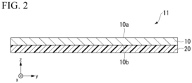
- the single-sided coated carbon fiber bundle 11 comprises the carbon fiber bundle 10 having one main surface 10a and another main surface 10b on the opposite side, and a resin film 20 formed on the one main surface 10b.
- Heating by the heater 130 is performed for the purpose of melting the resin powder applied to the main surface 10b of the carbon fiber bundle.
- Pressing by the nip roll 140 is performed for the purpose of making a resin constituting the resin film 20 permeate the carbon fiber bundle 10.
- Cooling by the cooling roll 150 is performed for the purpose of solidifying the resin film 20 before the slitting step in the subsequent stage.
- the resin film 20 may be cooled by blowing cooling air in place of or in addition to use of the cooling roll 150.
- Either or both of the pressing by the nip roll 140 and the cooling by the cooling roll 150 may be omitted.
- the purpose of forming the resin film on one surface of the spread carbon fiber bundle before slitting it is stabilizing the shape of the carbon fiber bundle and maintaining it in a spread state.
- the resin film is formed for the purpose of preventing the spread carbon fiber bundle from decrease in a bundle width and increase and uniformity reduction in a thickness during transportation to a slitter roll.
- Formation of the resin film has also a purpose of stabilizing shapes of sub-bundles formed by slitting the carbon fiber bundle. There is an advantage that the sub-bundles are unlikely to be entangled with each other when the shapes of the sub-bundles are stable.
- the effect of stabilizing the shape of the carbon fiber bundle by forming the resin film is particularly significant when the filament number is 40 K or more, that is, when the carbon fiber bundle is a so-called large tow. This is because a binding effect of a sizing agent contained in the carbon fiber bundle weakens as the filament number increases.
- the resin film 20 may be a continuous film that completely covers the main surface 10b of the carbon fiber bundle 10, or may be a discontinuous film having an island structure or a network structure. When the resin film 20 is a discontinuous film, the main surface 10b of the carbon fiber bundle 10 is partially exposed.
- the resin film is the discontinuous film in terms of preventing occurrence of defective impregnation when the slit carbon fiber bundle manufactured from the single-sided coated carbon fiber bundle is used for manufacturing a prepreg.
- the resin film 20 is not limited by the kind of a resin constituting the resin film 20.
- one or more resins selected from polyamide, polyester, polyurethane, polyolefin, an epoxy resin, a phenol resin, a vinyl ester resin, and a silicone resin may be comprised in the resin film 20.
- the resin film 20 may comprise a resin composition containing a component other than the resin.
- the method for forming the resin film 20 is not limited to the method including spraying a resin powder.
- Various types of applicators such as a spray gun, a roll coater, and a die coater can be used when the resin film 20 is formed with a fusible resin.
- the single-sided coated carbon fiber bundle 11 is fed to the slitter roll 170 and partially slit to form the slit carbon fiber bundle 12.
- the slit is formed to penetrate through the single-sided coated carbon fiber bundle 11 in a thickness direction, that is, to penetrate through both the carbon fiber bundle 10 and the resin film 20.
- a slitting blade 171 provided on a circumferential surface 170a of the slitter roll 170 is provided with a missing part 172 for allowing partial slitting.
- the single-sided coated carbon fiber bundle 11 comprising the carbon fiber bundle with a filament number of NK is partially split into n (n represents an integer of 2 or more) sub-bundles by partially slitting using the slitter roll 170 having (n-1) slitting blades 171 arranged along a rotation axis direction.
- N/n is, for example, 10 or less, preferably 6 or less, more preferably 4 or less and may be 3 or less or 2 or less. N/n is preferably 0.5 or more and may be 1 or more. The above-described upper limit and lower limit can be arbitrarily combined. For example, N/n is preferably 0.5 to 6, more preferably 0.5 to 4, and still more preferably 0.5 to 3.
- a slit carbon fiber bundle comprising five sub-bundles obtained by partially slitting a single-sided coated carbon fiber bundle with a slitter roll having four slitting blades is shown in Figs. 3A and 3B .
- a fiber direction (longitudinal direction) is defined as an x-direction
- a width direction is defined as a y-direction
- a thickness direction is defined as a z-direction
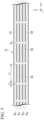
- Fig. 3A is a plan view when the slit carbon fiber bundle 12 is viewed in the z-direction
- Fig. 3B is a cross-sectional view showing a cross section perpendicular to the x-direction (cross section in a yz-plane) of the slit carbon fiber bundle 12.
- a first slit row A S1 As shown in Fig. 3A , four slit rows of a first slit row A S1 , a second slit row A S2 , a third slit row A S3 , and a fourth slit row A S4 are formed in the slit carbon fiber bundle 12.
- the first slit row A S1 consists of a plurality of first slits S1 arranged in the x-direction.
- the second slit row A S2 consists of a plurality of second slits S2 arranged in the x-direction.
- the third slit row A S3 consists of a plurality of third slits S3 arranged in the x-direction.
- the fourth slit row A S4 consists of a plurality of fourth slits S4 arranged in the x-direction.
- the four slit rows are formed by different slitting blades, and thus positions of the four slit rows in the y-direction are different from each other.
- a slit length L S and an inter-slit gap length L G are constant in any of the slit rows and are common in different slit rows.
- a ratio L S /(L S + L G ) of the slit length L S to the sum of the slit length L S and the inter-slit gap length L G is usually 90% or more and preferably 95% or more, and may be, for example, 99%. Therefore, the slit carbon fiber bundle 12 is split into five sub-bundles 12s in most parts as shown in Fig. 3B .
- Positions of the first slit row A S1 , the second slit row A S2 , the third slit row A S3 , and the fourth slit row A S4 in the y-direction are set such that the widths of the five sub-bundles 12s are approximately the same as each other.
- the slit length L S is not limited to, but is preferably more than 25 mm, more preferably more than 50 mm, and still more preferably more than 500 mm.
- the slit length L S can be more than 25 mm and 50 mm or less, more than 50 mm and 100 mm or less, more than 100 mm and 200 mm or less, more than 200 mm and 500 mm or less, more than 500 mm and 1000 mm or less, more than 1000 mm and 1500 mm or less, more than 1500 mm and 2000 mm or less, or more than 2000 mm and 3000 mm or less.
- the inter-slit gap length L G is not limited to, but is, for example, in a range of 5 to 10 mm.
- the slit length L S and the inter-slit gap length L G can be controlled by adjusting a feed speed of the single-sided coated carbon fiber bundle 11, a circumferential speed of the slitter roll 170, and lengths of the slitting blade 171 and the missing part 172 of the slitting blade in a circumferential direction.
- the slit length L S can be set to be greater than the length of the slitting blade 171 in the circumferential direction by adjusting the feed speed of the single-sided coated carbon fiber bundle 11 higher than the circumferential speed of the slitter roll.
- positions of the inter-slit gaps G S in the first slit row A S1 and the second slit row A S2 are shifted in the x-direction. The same applies between the second slit row A S2 and the third slit row A S3 and between the third slit row A S3 and the fourth slit row A S4 .
- the configuration in which the positions of the inter-slit gaps G S between the adjacent slit rows are shifted in the x-direction as described above is not essential.
- the positions of the inter-slit gaps G S in the x-direction may be aligned between all the slit rows as shown in Fig. 5 .
- the positions of the inter-slit gaps G S in the x-direction may be shifted between all the slit rows.
- the slit length L S , the inter-slit gap length L G , the ratio L S /(L S + L G ) of the slit length L S to the sum of the slit length L S and the inter-slit gap length L G , and the position of the inter-slit gap G S applies not only to the slit carbon fiber bundle comprising five sub-bundles but also to slit carbon fiber bundles comprising four or less or six or more sub-bundles.
- the filament number of each sub-bundle 12s in the slit carbon fiber bundle 12 is preferably 6K or less, more preferably 4K or less, and still more preferably 3K or less, regardless of the number n.
- the filament number of each sub-bundle 12s in the slit carbon fiber bundle 12 is preferably 0.5K or more and more preferably 1K or more, regardless of the number n.
- the above-described upper limit and lower limit can be arbitrarily combined.
- the filament number of each sub-bundle 12s in the slit carbon fiber bundle 12 is preferably in a range of 0.5K to 6K, more preferably in a range of 0.5K to 4K, and still more preferably in a range of 0.5K to 3K.
- the single-sided coated carbon fiber bundle may be fed while sliding on the circumferential surface 170a of the slitter roll by setting the feed speed of the single-sided coated carbon fiber bundle to be higher than the circumferential speed of the slitter roll, in order to form a slit that is longer than the length of the slitting blade 171 in the circumferential direction.
- the single-sided coated carbon fiber bundle 11 contacts the circumferential surface 170a of the slitter roll on a side where the resin film 20 has been formed, in order to prevent fuzzing resulting from breakage of a filament in the carbon fiber bundle 10 due to friction with the slitter roll 170.
- the slitting blade penetrates into the single-sided coated carbon fiber bundle 11 from the side of the resin film 20 not from the side of the carbon fiber bundle 10.
- an amount of fluff contained in the carbon fiber mat was different depending on a direction in which the slitting blade penetrated into the single-sided coated carbon fiber bundle in the preparation of the slit carbon fiber bundle. More specifically, when the slitting blade penetrated into the single-sided coated carbon fiber bundle from the side of the resin film in the slitting, the amount of fluff contained in the carbon fiber mat prepared by using the obtained slit carbon fiber bundle was smaller as compared with when the slitting blade penetrated thereinto from the side of the carbon fiber bundle.
- a single-sided coated carbon fiber bundle was prepared by spreading a carbon fiber bundle to have a width of approximately 25 mm, coating one surface thereof with an epoxy resin using a spray gun, and making a part of the epoxy resin permeate into the carbon fiber bundle by allowing the carbon fiber bundle passing through a nip roll heated to 150°C.
- the used epoxy resin was a bisphenol A type epoxy resin [jER (registered trademark) 1002, manufactured by Mitsubishi Chemical Corporation] having an epoxy equivalent of 600 to 700, a number average molecular weight of approximately 1200, and a softening point of 78°C (ring and ball method).
- the amount of the epoxy resin adhered to the carbon fiber bundle in this processing was approximately 7% by weight of the single-sided coated carbon fiber bundle.
- a plurality of slitting blades were provided with a pitch of 0.85 mm in an axial direction on a circumferential surface of a slitter roll used in the slitting.
- Each slitting blade had one missing part on its outer circumference.
- the slit length was approximately 700 mm, and the inter-slit gap length was approximately 10 mm.
- the carbon fiber mat was prepared by cutting the prepared slit carbon fiber bundle with a chopper to form a chopped carbon fiber bundle such that a fiber length thereof is 25 mm, bringing the chopped carbon fiber bundle into contact with a rotating pin roll, and subsequently dropping the chopped carbon fiber bundle on a resin film.
- the circumferential speed of the pin roll was approximately 400 m/min at the tip of a pin.
- the slit carbon fiber bundle 12 obtained by partially slitting the single-sided coated carbon fiber bundle 11 is wound on a bobbin B2.
- the bobbin B2 is, for example, a paper tube, but is not limited thereto.
- a lead angle at the start of the winding can be set to, for example, 5° to 30°, and the lead angle at the end of the winding can be set to, for example, 2° to 17°, but the lead angles are not limited thereto.
- a winding ratio in the traverse-winding is usually not set to an integer, and it is preferable that the fraction after the decimal point of the winding ratio is also not set to a multiple of 1/2, 1/3, 1/4, and 1/5.
- the slit carbon fiber bundle 12 is wound on the bobbin such that no gap is present between the sub-bundles 12s.
- the reason is to prevent the sub-bundles 12s from biting each other between a part wound first on the bobbin B2 and a part later wound thereon in an overlapping manner.
- the winding is made such that no gap is present between the sub-bundles 12s, it is possible to suppress the sub-bundles from biting each other, and entanglement of the slit carbon fiber bundle 12 and breakage of the sub-bundles 12s can therefore be prevented when the slit carbon fiber bundle is unwound by external or internal unwinding.
- a total width W of the slit carbon fiber bundle 12 may be set to be less than a sum of widths W s of the sub-bundles as shown in Fig. 4 , in order to wind the slit carbon fiber bundle 12 on the bobbin such that no gap is present between the sub-bundles 12s.
- Fig. 4 is a cross-sectional view when the slit carbon fiber bundle 12 on the bobbin is cut perpendicularly to the fiber direction, showing that the five sub-bundles 12s are arranged without any gap in the y-direction. That is, there is no part where the adjacent sub-bundles 12s are apart from each other, and each sub-bundle 12s overlaps the sub-bundle 12s next to it at the edge.
- the slit carbon fiber bundle 12 can be wound on the bobbin B2 in a state where the total width W is less than the sum of the widths W s of the sub-bundles by using a grooved roll having a groove width smaller than the sum of the widths of the sub-bundles as a guide roll or adjusting the guide width of the traverse device to be smaller than the sum of the widths of the sub-bundles.
- a state of mutual overlapping between the sub-bundles in the slit carbon fiber bundle wound on the winding bobbin is not limited to that shown in Fig. 4 , but can be various.
- the total width of the slit carbon fiber bundle when wound on the winding bobbin is set to preferably 90% or less of the sum of the widths of the sub-bundles and more preferably 80% or less thereof.
- the slit carbon fiber bundle which was obtained by slitting the single-sided coated carbon fiber bundle having a width of 25 mm, was wound on a bobbin such that a total width thereof became approximately 13 mm, and the slit carbon fiber bundle was unwound and used to prepare the carbon fiber mat.
- the slit carbon fiber bundle was unwound, entanglement of the slit carbon fiber bundle or breakage of the sub-bundles did not occur.
- the slit carbon fiber bundle 12 can be preferably used as a material for SMC.
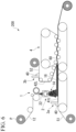
- an SMC manufacturing apparatus shown in Fig. 6 can be used for manufacturing SMC using the slit carbon fiber bundle 12.
- the SMC manufacturing apparatus includes a chopper 1, a disperser 2, a first applicator 3a, a second applicator 3b, and an impregnation machine 4.
- the slit carbon fiber bundle 12 is drawn out from a carbon fiber package P and sent to the chopper 1.
- the slit carbon fiber bundle 12 is cut by the chopper 1, thereby forming a chopped carbon fiber bundle 14.
- the fiber length of the chopped carbon fiber bundle 14 is, for example, within a range of 5 mm to 100 mm and typically 1.3 cm (approximately 1/2 inches), 2.5 cm (approximately 1 inch), or the like.
- the chopped carbon fiber bundle 14 falls on a first carrier film 51 travelling below the chopper while being dispersed by the disperser 2 having one or more rotating body.
- a carbon fiber mat 16 is deposited on the first carrier film 51.
- a pin roll 263a shown in Fig. 7 is an example of the rotating body of the disperser 2.
- a structural body in which a pair of disks 412 are connected with a plurality of wires or rods 414 as shown in Fig. 8 is another example of the rotating body of the disperser 2.
- the surface of the first carrier film 51 is coated with a resin paste layer 41 comprising thermosetting resin paste 40 by the first applicator 3a before the deposition of the carbon fiber mat 16.
- a second carrier film 52 is also coated with a resin paste layer 42 comprising the thermosetting resin paste 40 by the second applicator 3b.
- Both the first carrier film 51 and the second carrier film 52 are synthetic resin films and comprises, for example, polyolefin.
- a laminate 60 is formed by laminating the first carrier film 51 and the second carrier film 52 such that the resin paste layer respectively applied to the first carrier film and the second carrier film and the carbon fiber mat 16 are sandwiched therebetween.
- the carbon fiber mat 16 is impregnated with the thermosetting resin paste 40 by pressing the laminate 60 with the impregnation machine 4.
- the laminate 60 having passed through the impregnation machine 4 is wound on a bobbin.
- the laminate 60 on the bobbin is heated to a predetermined temperature and maintained for a certain period of time in order to further thicken the thermosetting resin paste 40 that has permeated into the carbon fiber mat 16, as necessary.
- the slitting device 100 may be connected inline to the SMC manufacturing apparatus. That is, the slit carbon fiber bundle 12 manufactured by the slitting device 100 may be provided for manufacturing SMC without being wound on the bobbin even once.
Landscapes
- Engineering & Computer Science (AREA)
- Textile Engineering (AREA)
- Chemical & Material Sciences (AREA)
- Chemical Kinetics & Catalysis (AREA)
- Mechanical Engineering (AREA)
- General Chemical & Material Sciences (AREA)
- Reinforced Plastic Materials (AREA)
- Inorganic Fibers (AREA)
- Preliminary Treatment Of Fibers (AREA)
Claims (12)
- Enroulement de fibres de carbone (P) dans lequel un faisceau de fibres de carbone avec fente (12), qui a été divisé en sous-faisceaux (12s) par une division partielle, est enroulé de manière transversale sur une bobine (B2),dans lequel le faisceau de fibres de carbone avec fente a été préparé en divisant partiellement un faisceau de fibres de carbone revêtu d'un seul côté (11) comprenant un faisceau de fibres de carbone plat (10) et un film de résine (20) formé sur une surface (10b) du faisceau de fibres de carbone plat ; caractérisé en ce queune largeur (W) du faisceau de fibres de carbone avec fente sur la bobine est inférieure à une somme de largeurs (Ws) des sous-faisceaux.
- Enroulement de fibres de carbone selon la revendication 1,
dans lequel le faisceau de fibres de carbone avec fente est enroulé sur la bobine de sorte qu'aucun espace ne soit présent entre les sous-faisceaux. - Enroulement de fibres de carbone selon la revendication 1 ou 2,
dans lequel le film de résine est un film discontinu. - Enroulement de fibres de carbone selon l'une quelconque des revendications 1 à 3,
dans lequel le film de résine comprend une ou plusieurs résines sélectionnées parmi polyamide, polyester, polyuréthane, polyoléfine, une résine époxy, une résine phénol, une résine vinylester, et une résine silicone. - Procédé de fabrication d'un enroulement de fibres de carbone (P), comprenant :l'enroulement transversal d'un faisceau de fibres de carbone avec fente (12), qui a été divisé en sous-faisceaux (12s) par une division partielle, sur une bobine (B2),dans lequel le faisceau de fibres de carbone avec fente a été préparé en divisant partiellement un faisceau de fibres de carbone revêtu d'un seul côté (11) comprenant un faisceau de fibres de carbone plat (10) et un film de résine (20) formé sur une surface (10b) du faisceau de fibres de carbone plat ;caractérisé en ce quele faisceau de fibres de carbone avec fente est enroulé sur la bobine de sorte qu'une largeur (W) du faisceau de fibres de carbone avec fente sur la bobine soit inférieure à une somme de largeurs (Ws) des sous-faisceaux.
- Procédé de fabrication selon la revendication 5,
dans lequel le faisceau de fibres de carbone avec fente est enroulé sur la bobine de sorte qu'aucun espace ne soit présent entre les sous-faisceaux. - Procédé de fabrication selon la revendication 5 ou 6,
dans lequel le film de résine est un film discontinu. - Procédé de fabrication selon l'une quelconque des revendications 5 à 7,
dans lequel un nombre de filaments du faisceau de fibres de carbone plat est 12K ou plus et
peut être 100K ou moins. - Procédé de fabrication selon la revendication 8,
dans lequel le nombre de filaments du faisceau de fibres de carbone plat est 40K ou plus. - Procédé de fabrication selon l'une quelconque des revendications 5 à 9,
dans lequel lorsqu'un nombre de filaments du faisceau de fibres de carbone plat est NK, et le nombre des sous-faisceaux est n, N/n est 10 ou moins. - Procédé de fabrication selon la revendication 10,
dans lequel N/n est 0,5 ou plus. - Procédé de fabrication selon l'une quelconque des revendications 5 à 11,
dans lequel le film de résine comprend une ou plusieurs résines sélectionnées parmi polyamide, polyester, polyuréthane, polyoléfine, une résine époxy, une résine phénol, une résine vinylester, et une résine silicone.
Applications Claiming Priority (2)
| Application Number | Priority Date | Filing Date | Title |
|---|---|---|---|
| JP2020099997 | 2020-06-09 | ||
| PCT/JP2021/020779 WO2021251205A1 (fr) | 2020-06-09 | 2021-06-01 | Procédé de production d'un faisceau de fibres de carbone avec fente, enroulement de fibres de carbone et procédé de production d'un enroulement de fibres de carbone |
Publications (3)
| Publication Number | Publication Date |
|---|---|
| EP4163426A1 EP4163426A1 (fr) | 2023-04-12 |
| EP4163426A4 EP4163426A4 (fr) | 2024-07-24 |
| EP4163426B1 true EP4163426B1 (fr) | 2025-05-21 |
Family
ID=78845631
Family Applications (1)
| Application Number | Title | Priority Date | Filing Date |
|---|---|---|---|
| EP21821463.3A Active EP4163426B1 (fr) | 2020-06-09 | 2021-06-01 | Procédé de production d'un faisceau de fibres de carbone avec fente, enroulement de fibres de carbone et procédé de production d'un enroulement de fibres de carbone |
Country Status (7)
| Country | Link |
|---|---|
| US (1) | US20230103035A1 (fr) |
| EP (1) | EP4163426B1 (fr) |
| JP (1) | JPWO2021251205A1 (fr) |
| CN (1) | CN115698402A (fr) |
| ES (1) | ES3033411T3 (fr) |
| TW (1) | TWI823098B (fr) |
| WO (1) | WO2021251205A1 (fr) |
Families Citing this family (2)
| Publication number | Priority date | Publication date | Assignee | Title |
|---|---|---|---|---|
| ES3012109T3 (en) * | 2020-03-18 | 2025-04-08 | Mitsubishi Chem Corp | Smc manufacturing method |
| EP4545265A1 (fr) * | 2021-02-16 | 2025-04-30 | Mitsubishi Chemical Corporation | Procédé de production de composé de moulage en feuille, appareil de dépôt de mat de fibres de carbone et appareil de production de composé de moulage en feuille |
Family Cites Families (26)
| Publication number | Priority date | Publication date | Assignee | Title |
|---|---|---|---|---|
| US4220496A (en) * | 1979-02-01 | 1980-09-02 | Ppg Industries, Inc. | High strength composite of resin, helically wound fibers and chopped fibers and method of its formation |
| JP2845636B2 (ja) * | 1991-04-15 | 1999-01-13 | 東レ株式会社 | 繊維糸条巻取機用トラバースガイド |
| JP3722323B2 (ja) * | 1997-02-14 | 2005-11-30 | 東レ株式会社 | 炭素繊維とその製造方法および製造装置 |
| JP2002255448A (ja) * | 2001-03-05 | 2002-09-11 | Mitsubishi Rayon Co Ltd | 複数炭素繊維束巻取体、この複数炭素繊維束巻取体から各炭素繊維束を分割する装置及び方法 |
| KR101564801B1 (ko) * | 2008-11-10 | 2015-10-30 | 도레이 카부시키가이샤 | 실 연결 접합부를 갖는 섬유 다발, 및 그의 제조 방법, 및 탄소 섬유의 제조 방법 |
| JP5569708B2 (ja) * | 2009-01-15 | 2014-08-13 | 三菱レイヨン株式会社 | シートモールディングコンパウンドの製造方法 |
| JP5682139B2 (ja) * | 2009-05-22 | 2015-03-11 | 三菱レイヨン株式会社 | 炭素繊維束 |
| US9884740B2 (en) * | 2009-11-09 | 2018-02-06 | Toray Industries, Inc. | Fiber bundle with pieced part, process for producing same, and process for producing carbon fiber |
| JP2011241494A (ja) * | 2010-05-17 | 2011-12-01 | Toyota Motor Corp | 開繊シートの製造装置及びその製造方法 |
| US20120213997A1 (en) | 2011-02-21 | 2012-08-23 | United States Council For Automotive Research | Fiber tow treatment apparatus and system |
| WO2016117634A1 (fr) * | 2015-01-23 | 2016-07-28 | 東レ株式会社 | Rouleau et procédé de fabrication de rouleau de film de résine thermoplastique |
| EP4035860B1 (fr) * | 2015-07-07 | 2024-12-11 | Mitsubishi Chemical Corporation | Utilisation d'un faisceau de fibres continues dans des procédés de production de matériaux de moulage en résine renforcée par des fibres |
| GB201609919D0 (en) * | 2016-06-07 | 2016-07-20 | Fernando Gerard | Fibre spreading |
| JP7001997B2 (ja) * | 2016-06-21 | 2022-01-20 | 東レ株式会社 | 部分分繊繊維束とその製造方法、および部分分繊繊維束を用いた繊維強化樹脂成形材料とその製造方法 |
| CN109312505B (zh) * | 2016-06-22 | 2021-07-30 | 东丽株式会社 | 部分分纤纤维束及其制造方法、以及纤维增强树脂成型材料及其制造方法 |
| CA3024103A1 (fr) * | 2016-06-22 | 2017-12-28 | Toray Industries, Inc. | Procede de production de faisceau de fibres separees, faisceau de fibres separees, materiau de moulage de resine renforcee par des fibres mettant en oeuvre un faisceau de fibres s eparees et procede de production de materiau de moulage de resine renforcee par des fibres mettant en oeuvre un faisceau de fibres separees |
| EP3269859A1 (fr) * | 2016-07-15 | 2018-01-17 | Toray Carbon Fibers Europe | Mat aléatoire de fibres de carbone et matériau composite de fibre de carbone |
| JP6876267B2 (ja) * | 2016-11-10 | 2021-05-26 | 三菱ケミカル株式会社 | 繊維束の分割方法、長尺の繊維束、及び繊維強化樹脂材料の製造方法 |
| ES2975187T3 (es) * | 2017-02-02 | 2024-07-03 | Toray Industries | Haz de fibras parcialmente separadas y método para fabricar el mismo, haz de fibras cortadas usando el mismo, y material de formación de resina reforzada con fibra |
| US12018410B2 (en) * | 2017-09-21 | 2024-06-25 | Teijin Limited | Fixed carbon fiber bundle and method for producing fixed carbon fiber bundle |
| RU2020127571A (ru) * | 2018-02-01 | 2022-03-01 | Торэй Индастриз, Инк. | Пучок частично расщепленных волокон, промежуточный основной материал, формованное изделие и способ для их производства |
| CN112639188B (zh) * | 2018-09-28 | 2022-11-08 | 东丽株式会社 | 部分分纤纤维束及其制造方法 |
| JP6863478B2 (ja) * | 2018-10-19 | 2021-04-21 | 三菱ケミカル株式会社 | 炭素繊維束、炭素繊維束の製造方法、及びシートモールディングコンパウンドの製造方法 |
| JP7183023B2 (ja) | 2018-12-19 | 2022-12-05 | キヤノン株式会社 | 素子基板、液体吐出ヘッド、及び記録装置 |
| CN113365933B (zh) * | 2019-01-28 | 2023-07-18 | 三菱化学株式会社 | 纤维包装 |
| CN110948912B (zh) * | 2019-12-12 | 2021-09-28 | 国塑机械(上海)有限公司 | 一种热塑性连续碳纤维单向带的生产设备及生产工艺 |
-
2021
- 2021-06-01 EP EP21821463.3A patent/EP4163426B1/fr active Active
- 2021-06-01 CN CN202180040990.XA patent/CN115698402A/zh active Pending
- 2021-06-01 ES ES21821463T patent/ES3033411T3/es active Active
- 2021-06-01 JP JP2022530482A patent/JPWO2021251205A1/ja active Pending
- 2021-06-01 WO PCT/JP2021/020779 patent/WO2021251205A1/fr not_active Ceased
- 2021-06-02 TW TW110119975A patent/TWI823098B/zh active
-
2022
- 2022-12-02 US US18/073,861 patent/US20230103035A1/en not_active Abandoned
Also Published As
| Publication number | Publication date |
|---|---|
| ES3033411T3 (en) | 2025-08-04 |
| CN115698402A (zh) | 2023-02-03 |
| TW202206661A (zh) | 2022-02-16 |
| EP4163426A4 (fr) | 2024-07-24 |
| US20230103035A1 (en) | 2023-03-30 |
| EP4163426A1 (fr) | 2023-04-12 |
| TWI823098B (zh) | 2023-11-21 |
| WO2021251205A1 (fr) | 2021-12-16 |
| JPWO2021251205A1 (fr) | 2021-12-16 |
Similar Documents
| Publication | Publication Date | Title |
|---|---|---|
| EP4094914B1 (fr) | Procédé de fabrication de mélange à mouler en feuille (smc) | |
| US20230103035A1 (en) | Method for Producing Slit Carbon Fiber Bundle, Carbon Fiber Package, and Method for Producing Carbon Fiber Package | |
| US10626235B2 (en) | Flexible composite prepreg materials | |
| KR102048276B1 (ko) | Smc 제조방법 및 그 제조장치 | |
| EP4122666B1 (fr) | Procédé de fabrication de mélange à mouler en feuille (smc) | |
| US11220025B2 (en) | Methods of separating carbon fiber tows | |
| KR20150081277A (ko) | 섬유 프리폼들을 제조하기 위한 방법 | |
| US8789571B2 (en) | Prepreg manufacturing device | |
| US10907280B2 (en) | Production method for partially separated fiber bundle, partially separated fiber bundle, fiber-reinforced resin molding material using partially separated fiber bundle, and production method for fiber-reinforced resin molding material using partially separated fiber bundle | |
| US20150101756A1 (en) | Process | |
| US3113061A (en) | Method of making a glass reinforced fibrous web | |
| JP7209707B2 (ja) | 材料の巻き出し |
Legal Events
| Date | Code | Title | Description |
|---|---|---|---|
| STAA | Information on the status of an ep patent application or granted ep patent |
Free format text: STATUS: THE INTERNATIONAL PUBLICATION HAS BEEN MADE |
|
| PUAI | Public reference made under article 153(3) epc to a published international application that has entered the european phase |
Free format text: ORIGINAL CODE: 0009012 |
|
| STAA | Information on the status of an ep patent application or granted ep patent |
Free format text: STATUS: REQUEST FOR EXAMINATION WAS MADE |
|
| 17P | Request for examination filed |
Effective date: 20221207 |
|
| AK | Designated contracting states |
Kind code of ref document: A1 Designated state(s): AL AT BE BG CH CY CZ DE DK EE ES FI FR GB GR HR HU IE IS IT LI LT LU LV MC MK MT NL NO PL PT RO RS SE SI SK SM TR |
|
| DAV | Request for validation of the european patent (deleted) | ||
| DAX | Request for extension of the european patent (deleted) | ||
| A4 | Supplementary search report drawn up and despatched |
Effective date: 20240626 |
|
| RIC1 | Information provided on ipc code assigned before grant |
Ipc: D06M 15/643 20060101ALI20240620BHEP Ipc: D06M 15/564 20060101ALI20240620BHEP Ipc: D06M 15/55 20060101ALI20240620BHEP Ipc: D02J 1/22 20060101ALI20240620BHEP Ipc: D02J 13/00 20060101ALI20240620BHEP Ipc: D01F 9/12 20060101ALI20240620BHEP Ipc: D01D 5/42 20060101ALI20240620BHEP Ipc: B29B 15/12 20060101ALI20240620BHEP Ipc: D06M 101/40 20060101ALI20240620BHEP Ipc: B29K 105/14 20060101ALI20240620BHEP Ipc: D06M 15/59 20060101ALI20240620BHEP Ipc: D06H 7/04 20060101ALI20240620BHEP Ipc: B29B 11/16 20060101ALI20240620BHEP Ipc: D02J 1/18 20060101AFI20240620BHEP |
|
| GRAP | Despatch of communication of intention to grant a patent |
Free format text: ORIGINAL CODE: EPIDOSNIGR1 |
|
| STAA | Information on the status of an ep patent application or granted ep patent |
Free format text: STATUS: GRANT OF PATENT IS INTENDED |
|
| INTG | Intention to grant announced |
Effective date: 20241122 |
|
| RIN1 | Information on inventor provided before grant (corrected) |
Inventor name: KANEHAGI, JUNJI Inventor name: MIZUTORI, YUKIHIRO Inventor name: OKAMOTO, SATOSHI |
|
| GRAJ | Information related to disapproval of communication of intention to grant by the applicant or resumption of examination proceedings by the epo deleted |
Free format text: ORIGINAL CODE: EPIDOSDIGR1 |
|
| STAA | Information on the status of an ep patent application or granted ep patent |
Free format text: STATUS: REQUEST FOR EXAMINATION WAS MADE |
|
| GRAP | Despatch of communication of intention to grant a patent |
Free format text: ORIGINAL CODE: EPIDOSNIGR1 |
|
| STAA | Information on the status of an ep patent application or granted ep patent |
Free format text: STATUS: GRANT OF PATENT IS INTENDED |
|
| INTC | Intention to grant announced (deleted) | ||
| INTG | Intention to grant announced |
Effective date: 20250207 |
|
| GRAS | Grant fee paid |
Free format text: ORIGINAL CODE: EPIDOSNIGR3 |
|
| GRAA | (expected) grant |
Free format text: ORIGINAL CODE: 0009210 |
|
| STAA | Information on the status of an ep patent application or granted ep patent |
Free format text: STATUS: THE PATENT HAS BEEN GRANTED |
|
| P01 | Opt-out of the competence of the unified patent court (upc) registered |
Free format text: CASE NUMBER: APP_13459/2025 Effective date: 20250319 |
|
| AK | Designated contracting states |
Kind code of ref document: B1 Designated state(s): AL AT BE BG CH CY CZ DE DK EE ES FI FR GB GR HR HU IE IS IT LI LT LU LV MC MK MT NL NO PL PT RO RS SE SI SK SM TR |
|
| REG | Reference to a national code |
Ref country code: GB Ref legal event code: FG4D |
|
| REG | Reference to a national code |
Ref country code: CH Ref legal event code: EP |
|
| REG | Reference to a national code |
Ref country code: DE Ref legal event code: R096 Ref document number: 602021031228 Country of ref document: DE |
|
| REG | Reference to a national code |
Ref country code: IE Ref legal event code: FG4D |
|
| PGFP | Annual fee paid to national office [announced via postgrant information from national office to epo] |
Ref country code: DE Payment date: 20250624 Year of fee payment: 5 |
|
| PGFP | Annual fee paid to national office [announced via postgrant information from national office to epo] |
Ref country code: FR Payment date: 20250624 Year of fee payment: 5 |
|
| PGFP | Annual fee paid to national office [announced via postgrant information from national office to epo] |
Ref country code: AT Payment date: 20250721 Year of fee payment: 5 |
|
| REG | Reference to a national code |
Ref country code: ES Ref legal event code: FG2A Ref document number: 3033411 Country of ref document: ES Kind code of ref document: T3 Effective date: 20250804 |
|
| REG | Reference to a national code |
Ref country code: NL Ref legal event code: MP Effective date: 20250521 |
|
| PG25 | Lapsed in a contracting state [announced via postgrant information from national office to epo] |
Ref country code: PT Free format text: LAPSE BECAUSE OF FAILURE TO SUBMIT A TRANSLATION OF THE DESCRIPTION OR TO PAY THE FEE WITHIN THE PRESCRIBED TIME-LIMIT Effective date: 20250922 Ref country code: FI Free format text: LAPSE BECAUSE OF FAILURE TO SUBMIT A TRANSLATION OF THE DESCRIPTION OR TO PAY THE FEE WITHIN THE PRESCRIBED TIME-LIMIT Effective date: 20250521 |
|
| REG | Reference to a national code |
Ref country code: LT Ref legal event code: MG9D |
|
| PG25 | Lapsed in a contracting state [announced via postgrant information from national office to epo] |
Ref country code: NO Free format text: LAPSE BECAUSE OF FAILURE TO SUBMIT A TRANSLATION OF THE DESCRIPTION OR TO PAY THE FEE WITHIN THE PRESCRIBED TIME-LIMIT Effective date: 20250821 Ref country code: GR Free format text: LAPSE BECAUSE OF FAILURE TO SUBMIT A TRANSLATION OF THE DESCRIPTION OR TO PAY THE FEE WITHIN THE PRESCRIBED TIME-LIMIT Effective date: 20250822 |
|
| PG25 | Lapsed in a contracting state [announced via postgrant information from national office to epo] |
Ref country code: NL Free format text: LAPSE BECAUSE OF FAILURE TO SUBMIT A TRANSLATION OF THE DESCRIPTION OR TO PAY THE FEE WITHIN THE PRESCRIBED TIME-LIMIT Effective date: 20250521 Ref country code: PL Free format text: LAPSE BECAUSE OF FAILURE TO SUBMIT A TRANSLATION OF THE DESCRIPTION OR TO PAY THE FEE WITHIN THE PRESCRIBED TIME-LIMIT Effective date: 20250521 |
|
| PGFP | Annual fee paid to national office [announced via postgrant information from national office to epo] |
Ref country code: IT Payment date: 20250620 Year of fee payment: 5 |
|
| PG25 | Lapsed in a contracting state [announced via postgrant information from national office to epo] |
Ref country code: BG Free format text: LAPSE BECAUSE OF FAILURE TO SUBMIT A TRANSLATION OF THE DESCRIPTION OR TO PAY THE FEE WITHIN THE PRESCRIBED TIME-LIMIT Effective date: 20250521 |
|
| PG25 | Lapsed in a contracting state [announced via postgrant information from national office to epo] |
Ref country code: HR Free format text: LAPSE BECAUSE OF FAILURE TO SUBMIT A TRANSLATION OF THE DESCRIPTION OR TO PAY THE FEE WITHIN THE PRESCRIBED TIME-LIMIT Effective date: 20250521 |
|
| PG25 | Lapsed in a contracting state [announced via postgrant information from national office to epo] |
Ref country code: RS Free format text: LAPSE BECAUSE OF FAILURE TO SUBMIT A TRANSLATION OF THE DESCRIPTION OR TO PAY THE FEE WITHIN THE PRESCRIBED TIME-LIMIT Effective date: 20250821 |
|
| PG25 | Lapsed in a contracting state [announced via postgrant information from national office to epo] |
Ref country code: IS Free format text: LAPSE BECAUSE OF FAILURE TO SUBMIT A TRANSLATION OF THE DESCRIPTION OR TO PAY THE FEE WITHIN THE PRESCRIBED TIME-LIMIT Effective date: 20250921 |
|
| PG25 | Lapsed in a contracting state [announced via postgrant information from national office to epo] |
Ref country code: LV Free format text: LAPSE BECAUSE OF FAILURE TO SUBMIT A TRANSLATION OF THE DESCRIPTION OR TO PAY THE FEE WITHIN THE PRESCRIBED TIME-LIMIT Effective date: 20250521 |
|
| REG | Reference to a national code |
Ref country code: AT Ref legal event code: MK05 Ref document number: 1796824 Country of ref document: AT Kind code of ref document: T Effective date: 20250521 |
|
| PG25 | Lapsed in a contracting state [announced via postgrant information from national office to epo] |
Ref country code: AT Free format text: LAPSE BECAUSE OF FAILURE TO SUBMIT A TRANSLATION OF THE DESCRIPTION OR TO PAY THE FEE WITHIN THE PRESCRIBED TIME-LIMIT Effective date: 20250521 Ref country code: DK Free format text: LAPSE BECAUSE OF FAILURE TO SUBMIT A TRANSLATION OF THE DESCRIPTION OR TO PAY THE FEE WITHIN THE PRESCRIBED TIME-LIMIT Effective date: 20250521 Ref country code: SM Free format text: LAPSE BECAUSE OF FAILURE TO SUBMIT A TRANSLATION OF THE DESCRIPTION OR TO PAY THE FEE WITHIN THE PRESCRIBED TIME-LIMIT Effective date: 20250521 |
|
| PG25 | Lapsed in a contracting state [announced via postgrant information from national office to epo] |
Ref country code: CZ Free format text: LAPSE BECAUSE OF FAILURE TO SUBMIT A TRANSLATION OF THE DESCRIPTION OR TO PAY THE FEE WITHIN THE PRESCRIBED TIME-LIMIT Effective date: 20250521 |
|
| PG25 | Lapsed in a contracting state [announced via postgrant information from national office to epo] |
Ref country code: EE Free format text: LAPSE BECAUSE OF FAILURE TO SUBMIT A TRANSLATION OF THE DESCRIPTION OR TO PAY THE FEE WITHIN THE PRESCRIBED TIME-LIMIT Effective date: 20250521 |
|
| PG25 | Lapsed in a contracting state [announced via postgrant information from national office to epo] |
Ref country code: SK Free format text: LAPSE BECAUSE OF FAILURE TO SUBMIT A TRANSLATION OF THE DESCRIPTION OR TO PAY THE FEE WITHIN THE PRESCRIBED TIME-LIMIT Effective date: 20250521 |
|
| REG | Reference to a national code |
Ref country code: CH Ref legal event code: H13 Free format text: ST27 STATUS EVENT CODE: U-0-0-H10-H13 (AS PROVIDED BY THE NATIONAL OFFICE) Effective date: 20260127 |
|
| PG25 | Lapsed in a contracting state [announced via postgrant information from national office to epo] |
Ref country code: RO Free format text: LAPSE BECAUSE OF FAILURE TO SUBMIT A TRANSLATION OF THE DESCRIPTION OR TO PAY THE FEE WITHIN THE PRESCRIBED TIME-LIMIT Effective date: 20250521 |
|
| PG25 | Lapsed in a contracting state [announced via postgrant information from national office to epo] |
Ref country code: LU Free format text: LAPSE BECAUSE OF NON-PAYMENT OF DUE FEES Effective date: 20250601 |
|
| PG25 | Lapsed in a contracting state [announced via postgrant information from national office to epo] |
Ref country code: MC Free format text: LAPSE BECAUSE OF FAILURE TO SUBMIT A TRANSLATION OF THE DESCRIPTION OR TO PAY THE FEE WITHIN THE PRESCRIBED TIME-LIMIT Effective date: 20250521 |
|
| REG | Reference to a national code |
Ref country code: DE Ref legal event code: R097 Ref document number: 602021031228 Country of ref document: DE |
|
| REG | Reference to a national code |
Ref country code: BE Ref legal event code: MM Effective date: 20250630 |
|
| PLBE | No opposition filed within time limit |
Free format text: ORIGINAL CODE: 0009261 |
|
| STAA | Information on the status of an ep patent application or granted ep patent |
Free format text: STATUS: NO OPPOSITION FILED WITHIN TIME LIMIT |
|
| REG | Reference to a national code |
Ref country code: CH Ref legal event code: L10 Free format text: ST27 STATUS EVENT CODE: U-0-0-L10-L00 (AS PROVIDED BY THE NATIONAL OFFICE) Effective date: 20260402 |
|
| PG25 | Lapsed in a contracting state [announced via postgrant information from national office to epo] |
Ref country code: IE Free format text: LAPSE BECAUSE OF NON-PAYMENT OF DUE FEES Effective date: 20250601 |
|
| PG25 | Lapsed in a contracting state [announced via postgrant information from national office to epo] |
Ref country code: BE Free format text: LAPSE BECAUSE OF NON-PAYMENT OF DUE FEES Effective date: 20250630 |
|
| PG25 | Lapsed in a contracting state [announced via postgrant information from national office to epo] |
Ref country code: CH Free format text: LAPSE BECAUSE OF NON-PAYMENT OF DUE FEES Effective date: 20250630 |
|
| 26N | No opposition filed |
Effective date: 20260224 |
|
| GBPC | Gb: european patent ceased through non-payment of renewal fee |
Effective date: 20250821 |