EP4163486B1 - Verfahren zur steuerung einer drehzahl einer abtriebswelle einer antriebseinheit - Google Patents
Verfahren zur steuerung einer drehzahl einer abtriebswelle einer antriebseinheit Download PDFInfo
- Publication number
- EP4163486B1 EP4163486B1 EP21201095.3A EP21201095A EP4163486B1 EP 4163486 B1 EP4163486 B1 EP 4163486B1 EP 21201095 A EP21201095 A EP 21201095A EP 4163486 B1 EP4163486 B1 EP 4163486B1
- Authority
- EP
- European Patent Office
- Prior art keywords
- value
- acceleration
- torque
- asm
- indicative
- Prior art date
- Legal status (The legal status is an assumption and is not a legal conclusion. Google has not performed a legal analysis and makes no representation as to the accuracy of the status listed.)
- Active
Links
Images


Classifications
-
- F—MECHANICAL ENGINEERING; LIGHTING; HEATING; WEAPONS; BLASTING
- F02—COMBUSTION ENGINES; HOT-GAS OR COMBUSTION-PRODUCT ENGINE PLANTS
- F02D—CONTROLLING COMBUSTION ENGINES
- F02D31/00—Use of speed-sensing governors to control combustion engines, not otherwise provided for
- F02D31/001—Electric control of rotation speed
-
- B—PERFORMING OPERATIONS; TRANSPORTING
- B60—VEHICLES IN GENERAL
- B60L—PROPULSION OF ELECTRICALLY-PROPELLED VEHICLES; SUPPLYING ELECTRIC POWER FOR AUXILIARY EQUIPMENT OF ELECTRICALLY-PROPELLED VEHICLES; ELECTRODYNAMIC BRAKE SYSTEMS FOR VEHICLES IN GENERAL; MAGNETIC SUSPENSION OR LEVITATION FOR VEHICLES; MONITORING OPERATING VARIABLES OF ELECTRICALLY-PROPELLED VEHICLES; ELECTRIC SAFETY DEVICES FOR ELECTRICALLY-PROPELLED VEHICLES
- B60L15/00—Methods, circuits, or devices for controlling the traction-motor speed of electrically-propelled vehicles
- B60L15/20—Methods, circuits, or devices for controlling the traction-motor speed of electrically-propelled vehicles for control of the vehicle or its driving motor to achieve a desired performance, e.g. speed, torque, programmed variation of speed
-
- B—PERFORMING OPERATIONS; TRANSPORTING
- B60—VEHICLES IN GENERAL
- B60L—PROPULSION OF ELECTRICALLY-PROPELLED VEHICLES; SUPPLYING ELECTRIC POWER FOR AUXILIARY EQUIPMENT OF ELECTRICALLY-PROPELLED VEHICLES; ELECTRODYNAMIC BRAKE SYSTEMS FOR VEHICLES IN GENERAL; MAGNETIC SUSPENSION OR LEVITATION FOR VEHICLES; MONITORING OPERATING VARIABLES OF ELECTRICALLY-PROPELLED VEHICLES; ELECTRIC SAFETY DEVICES FOR ELECTRICALLY-PROPELLED VEHICLES
- B60L2240/00—Control parameters of input or output; Target parameters
- B60L2240/10—Vehicle control parameters
- B60L2240/12—Speed
-
- B—PERFORMING OPERATIONS; TRANSPORTING
- B60—VEHICLES IN GENERAL
- B60L—PROPULSION OF ELECTRICALLY-PROPELLED VEHICLES; SUPPLYING ELECTRIC POWER FOR AUXILIARY EQUIPMENT OF ELECTRICALLY-PROPELLED VEHICLES; ELECTRODYNAMIC BRAKE SYSTEMS FOR VEHICLES IN GENERAL; MAGNETIC SUSPENSION OR LEVITATION FOR VEHICLES; MONITORING OPERATING VARIABLES OF ELECTRICALLY-PROPELLED VEHICLES; ELECTRIC SAFETY DEVICES FOR ELECTRICALLY-PROPELLED VEHICLES
- B60L2240/00—Control parameters of input or output; Target parameters
- B60L2240/10—Vehicle control parameters
- B60L2240/14—Acceleration
-
- B—PERFORMING OPERATIONS; TRANSPORTING
- B60—VEHICLES IN GENERAL
- B60L—PROPULSION OF ELECTRICALLY-PROPELLED VEHICLES; SUPPLYING ELECTRIC POWER FOR AUXILIARY EQUIPMENT OF ELECTRICALLY-PROPELLED VEHICLES; ELECTRODYNAMIC BRAKE SYSTEMS FOR VEHICLES IN GENERAL; MAGNETIC SUSPENSION OR LEVITATION FOR VEHICLES; MONITORING OPERATING VARIABLES OF ELECTRICALLY-PROPELLED VEHICLES; ELECTRIC SAFETY DEVICES FOR ELECTRICALLY-PROPELLED VEHICLES
- B60L2240/00—Control parameters of input or output; Target parameters
- B60L2240/40—Drive Train control parameters
- B60L2240/42—Drive Train control parameters related to electric machines
- B60L2240/421—Speed
-
- B—PERFORMING OPERATIONS; TRANSPORTING
- B60—VEHICLES IN GENERAL
- B60L—PROPULSION OF ELECTRICALLY-PROPELLED VEHICLES; SUPPLYING ELECTRIC POWER FOR AUXILIARY EQUIPMENT OF ELECTRICALLY-PROPELLED VEHICLES; ELECTRODYNAMIC BRAKE SYSTEMS FOR VEHICLES IN GENERAL; MAGNETIC SUSPENSION OR LEVITATION FOR VEHICLES; MONITORING OPERATING VARIABLES OF ELECTRICALLY-PROPELLED VEHICLES; ELECTRIC SAFETY DEVICES FOR ELECTRICALLY-PROPELLED VEHICLES
- B60L2240/00—Control parameters of input or output; Target parameters
- B60L2240/40—Drive Train control parameters
- B60L2240/42—Drive Train control parameters related to electric machines
- B60L2240/423—Torque
-
- F—MECHANICAL ENGINEERING; LIGHTING; HEATING; WEAPONS; BLASTING
- F02—COMBUSTION ENGINES; HOT-GAS OR COMBUSTION-PRODUCT ENGINE PLANTS
- F02D—CONTROLLING COMBUSTION ENGINES
- F02D41/00—Electrical control of supply of combustible mixture or its constituents
- F02D41/02—Circuit arrangements for generating control signals
- F02D41/14—Introducing closed-loop corrections
- F02D41/1401—Introducing closed-loop corrections characterised by the control or regulation method
- F02D2041/141—Introducing closed-loop corrections characterised by the control or regulation method using a feed-forward control element
-
- F—MECHANICAL ENGINEERING; LIGHTING; HEATING; WEAPONS; BLASTING
- F02—COMBUSTION ENGINES; HOT-GAS OR COMBUSTION-PRODUCT ENGINE PLANTS
- F02D—CONTROLLING COMBUSTION ENGINES
- F02D41/00—Electrical control of supply of combustible mixture or its constituents
- F02D41/02—Circuit arrangements for generating control signals
- F02D41/14—Introducing closed-loop corrections
- F02D41/1401—Introducing closed-loop corrections characterised by the control or regulation method
- F02D2041/1413—Controller structures or design
- F02D2041/1422—Variable gain or coefficients
-
- F—MECHANICAL ENGINEERING; LIGHTING; HEATING; WEAPONS; BLASTING
- F02—COMBUSTION ENGINES; HOT-GAS OR COMBUSTION-PRODUCT ENGINE PLANTS
- F02D—CONTROLLING COMBUSTION ENGINES
- F02D2200/00—Input parameters for engine control
- F02D2200/02—Input parameters for engine control the parameters being related to the engine
- F02D2200/10—Parameters related to the engine output, e.g. engine torque or engine speed
- F02D2200/1012—Engine speed gradient
-
- F—MECHANICAL ENGINEERING; LIGHTING; HEATING; WEAPONS; BLASTING
- F02—COMBUSTION ENGINES; HOT-GAS OR COMBUSTION-PRODUCT ENGINE PLANTS
- F02D—CONTROLLING COMBUSTION ENGINES
- F02D2200/00—Input parameters for engine control
- F02D2200/60—Input parameters for engine control said parameters being related to the driver demands or status
- F02D2200/604—Engine control mode selected by driver, e.g. to manually start particle filter regeneration or to select driving style
-
- F—MECHANICAL ENGINEERING; LIGHTING; HEATING; WEAPONS; BLASTING
- F02—COMBUSTION ENGINES; HOT-GAS OR COMBUSTION-PRODUCT ENGINE PLANTS
- F02D—CONTROLLING COMBUSTION ENGINES
- F02D2250/00—Engine control related to specific problems or objectives
- F02D2250/18—Control of the engine output torque
-
- F—MECHANICAL ENGINEERING; LIGHTING; HEATING; WEAPONS; BLASTING
- F02—COMBUSTION ENGINES; HOT-GAS OR COMBUSTION-PRODUCT ENGINE PLANTS
- F02D—CONTROLLING COMBUSTION ENGINES
- F02D2250/00—Engine control related to specific problems or objectives
- F02D2250/18—Control of the engine output torque
- F02D2250/24—Control of the engine output torque by using an external load, e.g. a generator
-
- F—MECHANICAL ENGINEERING; LIGHTING; HEATING; WEAPONS; BLASTING
- F02—COMBUSTION ENGINES; HOT-GAS OR COMBUSTION-PRODUCT ENGINE PLANTS
- F02D—CONTROLLING COMBUSTION ENGINES
- F02D2250/00—Engine control related to specific problems or objectives
- F02D2250/18—Control of the engine output torque
- F02D2250/26—Control of the engine output torque by applying a torque limit
Definitions
- the present invention relates to a method for controlling a rotational speed of an output shaft of a propulsion unit. Moreover, the present invention relates to a control unit for controlling a rotational speed of an output shaft of a propulsion unit. Furthermore, the present invention relates to a propulsion assembly. Additionally, the present invention relates to a vehicle.
- the invention can be applied in heavy-duty vehicles, such as trucks, buses and construction equipment. Although the invention will be described with respect to a truck, the invention is not restricted to this particular vehicle, but may also be used in other vehicles such as working machines or seagoing vessels such as boats. Moreover, the present invention may be used in stationary power generators and the like.
- the speed setpoint value may be set by an operator of the propulsion unit or the speed setpoint value may be set by a control assembly or similar equipment.
- US 7,788 018 B2 discloses a method for controlling an internal combustion engine having a common rail system together with individual accumulators.
- a rotational speed-control deviation is determined from a target rotational speed that represents the set point for an outer control loop to control the rotational speed, as well as from an actual rotational speed.
- a target torque is determined from the rotational speed-control deviation via a rotational speed controller as a master controller.
- WO 00/36475 A1 relates to a method for governing the speed of a device that involves generating a command signal based on a desired change in acceleration, the inertia of the device, and a load associated with the device.
- the command signal is output to actuating means for changing the acceleration of the device.
- a speed sensor provides a signal indicative of the speed of the device such as an engine, a movable machine, or a movable component of a machine.
- An error signal based on the difference between the actual speed of the device and the desired speed of the device is calculated.
- the desired change in acceleration is computed based on the error signal and a gain factor that is proportional to a desired response time of the control system.
- the desired change in acceleration is multiplied by an inertial gain factor that is derived from a previous command signal and the change in the speed of the device that resulted from a previous command signal.
- the inertial gain factor is computed and updated at selected intervals to account for changes in the inertia and load.
- WO 2019/207542 A1 relates to a control method for an internal combustion engine, carried out by means of a feedback control of the engine speed, based on an error of said engine speed, calculated between a reference value and a measured value of the speed, wherein said control comprises a sum of a proportional contribution and an integral contribution, the method comprising a step of adding a derivative contribution only when a first sign of said error and a second sign of a derivative of the engine speed are reciprocally concordant.
- EP 2 851 254 A1 relates to a vehicle control device capable of relatively readily setting an engine rotation speed to a rotation speed that achieves a comfortable riding and correcting the engine rotation speed while preventing change in the driving force of the vehicle, when the correction is necessary.
- a target engine rotation speed calculation unit calculates a basic target engine rotation speed; a rotation speed correction unit corrects the basic target engine rotation speed to determine the rotation speed resulting from the correction as a target engine rotation speed; and a target transmission ratio calculation unit calculates a target transmission ratio such that an actual engine rotation speed becomes equal to the target engine rotation speed.
- a driving force target calculation unit calculates a driving force target value that is a target value as to a driving force of a vehicle, based on the basic target engine rotation speed, and a target throttle opening degree calculation unit calculates a target throttle opening degree, based on the driving force target value based on the basic target engine rotation speed.
- an object of the invention is to enable that a rotational speed of an output shaft of a propulsion unit can be controlled in an appropriate manner.
- the object is achieved by a method according to claim 1.
- the first aspect of the present invention relates to a method for controlling a rotational speed of an output shaft of a propulsion unit.
- the method comprises:
- the method as recited above implies that different acceleration values may be obtained for different values of the acceleration setting member. This in turn implies that e.g. an operator of a propulsion unit may choose how quickly the actual speed value should approach the speed setpoint value. This will in turn present an operator or a control system with an increased versatility as regards the control of the propulsion unit.
- the term "acceleration setting member” relates to an entity that can be used by the acceleration value determination procedure.
- the “acceleration setting member” may be numeric value, such as an integer or a real number.
- different choices of the acceleration setting member may be expressed in other terms than numerical.
- choices for the acceleration setting member may be "low”, “medium” or “high”; “A”, “B” or “C” or similar.
- the torque conversion operation comprises forming a torque request sum by multiplying the acceleration value by a moment of inertia value, indicative of a moment of inertia associated with the propulsion unit, and adding thereto a resistive torque value, indicative of a resistive torque associated with the propulsion unit.
- the torque conversion operation further comprises adding a torque disturbance value, indicative of torque disturbance associated with the propulsion unit, to the torque request sum.
- the addition of the torque disturbance value implies that the torque request sum, and possibly also the torque request, may include a torque term that is not immediately derivable when studying e.g. the current state of the propulsion unit or the entity, such as a vehicle, powered by the propulsion unit.
- the torque disturbance value may be related to one or more of the following:
- the torque disturbance value is determined using values determined for at least one previous time instant for each one of an actual torque value, indicative of an actual torque of the output shaft, the moment of inertia value, the resistive torque value, the torque disturbance value and an actual acceleration value, indicative of an actual acceleration of said output shaft.
- each one of the actual torque value and the actual acceleration value can be determined by a sensor associated with the output shaft.
- the torque disturbance value may be determined using inter alia a torque disturbance value for at least one previous time instant.
- the method may comprise setting the torque disturbance value to be a predetermined value, for instance zero, at a certain time instant.
- the method may comprise setting the torque disturbance value to be zero when the propulsion unit is started.
- Determining the torque disturbance value using the above values implies an appropriately accurate estimate of the torque disturbance.
- the method further comprises using the torque request sum as the torque request value.
- the propulsion unit is connected to a drivetrain for propelling a vehicle and each one of the moment of inertia value and resistive torque value is determined on the basis of information indicative of at least a current operating condition of the drivetrain.
- a determination implies that current operating conditions, such as a current speed ratio between the propulsion unit and e.g. ground engaging members such as wheels, are duly accounted for.
- the information indicative of at least a current operating condition of the drivetrain may comprise information indicative of e.g. a road inclination, viz the inclination of the road on which the vehicle is travelling, vehicle acceleration and wheels speeds.
- the acceleration setting member being used by the acceleration conversion function, is from a predetermined set of acceleration setting members, the set comprising at least two different acceleration setting members, preferably the set comprising a continuous range of values for the acceleration setting member.
- a user or another system may select an appropriate acceleration setting members and thus arrive at an appropriate resulting value which may be used for arriving at an appropriate acceleration value.
- the method comprises selecting an acceleration setting member to be used by the acceleration conversion function.
- the acceleration value determination procedure further comprises determining an overshoot prediction value for the acceleration value and if the absolute value of the resulting value exceeds the absolute value of the overshoot prediction value, the acceleration value determination procedure sets the acceleration value to equal the overshoot prediction value, otherwise, the acceleration value determination procedure sets the acceleration value to equal the resulting value.
- the overshoot prediction value implies that the acceleration value may be kept within a reasonable range such that undesirably large acceleration amplitudes are avoided.
- the overshoot prediction value is determined using values determined for at least one previous time instant for each one of the speed setpoint value, the actual speed value, an actual torque value, indicative of an actual torque of the output shaft, the moment of inertia value, the resistive torque value and the torque disturbance value.
- the object is achieved by a device according to claim 8.
- the second aspect of the present invention relates to a control unit for controlling a rotational speed of an output shaft of a propulsion unit.
- the control unit is adapted to:
- the torque conversion operation comprises forming a torque request sum by multiplying the acceleration value by a moment of inertia value, indicative of a moment of inertia associated with the propulsion unit, and adding thereto a resistive torque value, indicative of a resistive torque associated with the propulsion unit.
- the torque conversion operation further comprises adding a torque disturbance value, indicative of torque disturbance associated with the propulsion unit, to the torque request sum.
- the torque disturbance value is determined using values determined for at least one previous time instant for each one of an actual torque value, indicative of an actual torque of the output shaft, the moment of inertia value, the resistive torque value, the torque disturbance value and an actual acceleration value, indicative of an actual acceleration of said output shaft.
- the torque disturbance value may be determined using inter alia a torque disturbance value for at least one previous time instant.
- the method may comprise setting the torque disturbance value to be a predetermined value, for instance zero, at a certain time instant.
- the method may comprise setting the torque disturbance value to be zero when the propulsion unit is started.
- control unit is adapted to use the torque request sum as the torque request value.
- the propulsion unit is connected to a drivetrain for propelling a vehicle and each one of the moment of inertia value and resistive torque value is determined on the basis on information indicative of at least a current operating condition of the drivetrain.
- the acceleration setting member being used by the acceleration conversion function, is from a predetermined set of acceleration setting members, the set comprising at least two different acceleration setting members, preferably the set comprising a continuous range of values for the acceleration setting member.
- the acceleration value determination procedure further comprises determining an overshoot prediction value for the acceleration value and if the absolute value of the resulting value exceeds the absolute value of the overshoot prediction value, the acceleration value determination procedure sets the acceleration value to equal the overshoot prediction value, otherwise, the acceleration value determination procedure sets the acceleration value to equal the resulting value.
- the overshoot prediction value is determined using values determined for at least one previous time instant for each one of the speed setpoint value, the actual speed value, an actual torque value, indicative of an actual torque of the output shaft, the moment of inertia value, the resistive torque value and the torque disturbance value.
- a third aspect of the invention relates to a propulsion assembly comprising a propulsion unit and a control unit according to the second aspect of the present invention.
- the propulsion assembly further comprises an acceleration setting arrangement adapted to receive a signal indicative of a selected acceleration setting and in response thereto issue the signal indicative of the acceleration setting member to the control unit.
- a fourth aspect of the invention relates to a vehicle comprising a control unit according to the second aspect of the invention or a propulsion assembly according to the third aspect of the present invention.
- the vehicle comprises a drivetrain for propelling the vehicle, the propulsion unit being connected to the drivetrain.
- the invention will be described below for a vehicle in the form of a truck 10 such as the truck illustrated in Fig. 1 .
- the truck 10 should be seen as an example of a vehicle which could comprise a control unit according to the present invention.
- the present invention may be implemented in a plurality of different types of vehicles.
- the present invention could be implemented in a truck, a tractor, a car, a bus, a work machine such as a wheel loader or any other type of construction equipment.
- the present invention need not be implanted in a vehicle, but may be used for a stationary propulsion unit, such as a power generator (not shown).
- the Fig. 1 vehicle comprises a powertrain 12 that in turn comprises a propulsion unit 14 and a drivetrain 16.
- the propulsion unit 14 may comprise or constitute an internal combustion engine and the drivetrain 16 may comprise a transmission assembly, such as a gearbox.
- the propulsion unit 14 comprises an output shaft 18.
- the output shaft 18 is connected to the drivetrain 16.
- the drivetrain 16 may be adapted to assume a plurality of different conditions with different speed ratios between the propulsion unit 14 and driving wheels 20 of the vehicle 10.
- the drivetrain 16 may comprise a stepped transmission assembly with a fixed set of speed ratios between the propulsion unit 14 and driving wheels 20 of the vehicle 10.
- the drivetrain 16 may comprise a stepless transmission assembly via which an infinite number set of speed ratios may be obtained between the propulsion unit 14 and driving wheels 20 of the vehicle 10.
- Fig. 1 further illustrates that the vehicle 10 may comprise a control unit 22 as will be presented further hereinbelow.
- the propulsion unit 14 and the control unit 22 may be regarded as forming part of a propulsion assembly.
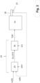
- Fig. 2 schematically illustrates a block diagram of an embodiment of a control unit 22 in accordance with the present invention.
- the Fig. 2 control unit 22 is adapted to control a rotational speed of an output shaft 18 of a propulsion unit 14.
- the control unit 22 is adapted to receive information relating to a speed setpoint value ⁇ s (k), indicative of a rotational speed setpoint for the output shaft 18, and an actual speed value ⁇ (k), indicative of an actual rotational speed of the output shaft 18.
- the parameter k may either be a real number (for instance indicating an actual time instant) or an integer indicating a reference index for a certain time instant such that two adjacent values of the parameter k, such as k-1 and k, indicate adjacent occurrences in time.
- the temporal distance between two adjacent parameter values, such as k-1 and k may be a predetermined time increment.
- the parameter k may be related to certain conditions in an internal combustion engine. Consequently, the temporal distance between two adjacent values of the parameter k may be dependent on the current operating condition of the propulsion unit.
- k is used as an integer.
- the Fig. 2 embodiment of the control unit 22 comprises an acceleration controller 24 adapted to receive the above two values ⁇ s (k), w(k). Moreover, the control unit 22 is adapted to receive information relating to an acceleration setting member asm. In the Fig. 2 embodiment, the acceleration controller 24 is adapted to receive information relating to an acceleration setting member asm.
- control unit 22 is adapted to determine an acceleration value ⁇ ⁇ s (k) ⁇ using an acceleration value determination procedure comprising employing an acceleration conversion function that uses the speed setpoint value ⁇ s (k), the actual speed value w(k) and the acceleration setting member asm as inputs and which produces a resulting value ⁇ s (k) to be used for determining the acceleration value ⁇ ⁇ s (k) ⁇ .
- the acceleration conversion function is such that different resulting values ⁇ s (k) can be obtained for the same set of the speed setpoint value ⁇ s (k) and the actual speed value w(k) but for different choices of the acceleration setting member asm.
- the relation between the resulting value ⁇ s (k) and the acceleration value ⁇ s (k) ⁇ will be presented hereinbelow with reference to Fig. 3 .
- control unit 22 is adapted to determine a torque request value T s (k) using a torque conversion operation that uses the acceleration value ⁇ ⁇ s (k) ⁇ and to issue a signal indicative of the torque request value T s (k) to the propulsion unit 14.
- the Fig. 2 embodiment of the control unit 22 comprises a torque controller 26 adapted to issue the signal indicative of the torque request value T s (k) to the propulsion unit 14 using the acceleration value ⁇ s (k) ⁇ .
- FIG. 3 illustrates an example implementation of the acceleration controller 24 introduced in relation to Fig. 2 .
- the Fig. 3 implementation of the acceleration controller 24 comprises a summing point 28, an acceleration converter 30 and an overshoot predictor 32.
- the propulsion assembly - which has been introduced hereinabove and which comprises the propulsion unit 14 and the control unit 22 - may further comprise an acceleration setting arrangement 34 adapted to receive a signal indicative of a selected acceleration setting and in response thereto issue the signal indicative of the acceleration setting member asm to the control unit.
- such an acceleration setting arrangement 34 may comprise a human-machine interface such as a lever, knob, touch screen or the like, via which an operator may select a preferred acceleration setting member asm.
- the acceleration setting arrangement 34 may be adapted so as to automatically set the acceleration setting member asm.
- the acceleration setting member is from a predetermined set of acceleration setting members, the set comprising at least two different acceleration setting members. Preferably the set comprising a continuous range of values for the acceleration setting member.
- the set of acceleration setting members may comprise a limited set of values which may for instance be selected from a look-up table or the like.
- f ⁇ e k , asm ⁇ e k ⁇ asm
- the ⁇ s (k) may be dependent on the square of the acceleration setting member asm or the like.
- the speed error ⁇ e (k) need not be explicitly determined.
- the function f in Eq. 4 hereinabove need not necessarily determine the difference between the speed setpoint value ⁇ s (k) and the actual speed value ⁇ (k).
- the function f in Eq. 4 may refer to a table, such as a look-up table from which resulting values ⁇ s (k) can be looked up and/or interpolated using the speed setpoint value ⁇ s (k), the actual speed value w(k) and the acceleration setting member asm. Irrespective of how the resulting value ⁇ s (k) is determined, it is used for determining the acceleration value ⁇ s (k) ⁇ .
- the acceleration value ⁇ ⁇ s (k) ⁇ can be set to equal the resulting value ⁇ s (k).
- the acceleration value determination procedure may further comprise determining an overshoot prediction value for the acceleration value and if the absolute value of the resulting value exceeds the absolute value of the overshoot prediction value, the acceleration value determination procedure sets the acceleration value to equal the overshoot prediction value. Otherwise, the acceleration value determination procedure sets the acceleration value to equal the resulting value.
- the overshoot predictor 32 in Fig. 3 although the feature of determining an overshoot prediction value may be implemented in a plurality of different ways.
- the overshoot prediction value may use values determined for at least one previous time instant for each one of the speed setpoint value ⁇ s (k), the actual speed value ⁇ (k), an actual torque value, indicative of an actual torque of the output shaft 18, a moment of inertia value, a resistive torque value and a torque disturbance value.
- the entities relating to each one of: the actual torque value, the moment of inertia value, the resistive torque value and the torque disturbance value will be presented hereinbelow.
- such a conversion may for instance be performed by the torque controller 26 in Fig. 2 .
- the torque conversion operation comprises forming a torque request sum by multiplying the acceleration value by a moment of inertia value, indicative of a moment of inertia associated with the propulsion unit, and adding thereto a resistive torque value, indicative of a resistive torque associated with the propulsion unit.
- the control unit 22 is adapted to use the torque request sum as the torque request value.
- T k J ⁇ k ⁇ ⁇ ⁇ s k + T ⁇ r k
- the torque request sum T(k) may be modified further, e.g. by putting overshoot or undershoot constraints thereon, before forming the torque request value T s ( k ).
- the torque request value T s ( k ) may be set so as to equal the torque request sum T(k).
- the torque conversion operation further comprises adding a torque disturbance value, indicative of torque disturbance associated with the propulsion unit, to the torque request sum.
- a torque disturbance value indicative of torque disturbance associated with the propulsion unit
- the torque disturbance value T ⁇ d ( k ) is determined using values determined for at least one previous time instant for each one of an actual torque value T a ( k - 1), the moment of inertia value ⁇ ( k - 1), the resistive torque value T ⁇ r (k - 1), the torque disturbance value T ⁇ d (k - 1) and an actual acceleration value ⁇ (k).
- the torque disturbance value T ⁇ d ( k - 1) for at least one previous time instant k - 1 may be set to zero when starting the procedure for determining the torque disturbance value T ⁇ d ( k ).
- the propulsion unit 14 may be connected to a drivetrain 16 for propelling a vehicle 10. Moreover, each one of the moment of inertia value ⁇ ( k ) and resistive torque value T ⁇ r ( k ) may be determined on the basis on information indicative of at least a current operating condition of the drivetrain 16.
- the torque controller 26 may receive a signal ocs indicative of a current operating condition of the drivetrain 16.
- the signal ocs indicative of the current operating condition of the drivetrain 16 may comprise, or even consist of, information indicative of a current speed ratio, e.g. between the propulsion unit 14 and driving wheels 20 of the vehicle 10 as mentioned hereinabove.
- the moment of inertia value ⁇ ( k ) may be dependent on the current speed ratio.
- each one of the moment of inertia value ⁇ ( k ) and resistive torque value T ⁇ r ( k ) may be dependent on additional parameters.
- additional parameters may for instance comprise information such as road inclination, viz the inclination of the road on which the vehicle is travelling, vehicle acceleration and wheel speeds.
- the signal ocs indicative of the current operating condition of the drivetrain 16 may comprise information indicative of the conditions of a vehicle that the propulsion unit 14 is propelling.
- the ocs may comprise information indicative of the for instance the actual torque T a ( k ) being produced by the propulsion unit 14.
- the powertrain 12 may comprise a sensor 23 adapted to determine information indicative of the current operating condition of the propulsion unit 14, such as the current operating condition of the drivetrain 16 and/or the actual torque T a ( k ) .
- a sensor 23 may be adapted to be in communication with one or more portions of the control unit, such as the torque controller 26, such that information determined by the sensor 23 may be forwarded to the relevant portions of the control unit 22.
- propulsion unit 14 for instance be it an internal combustion engine or an electric machine or a combination thereof
- propulsion unit 14 certain implementations for an internal combustion engine will be presented hereinbelow.
- the below examples are presented in relation to a six-cylinder internal combustion engine, such as a six-cylinder diesel engine.
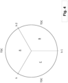
- Fig. 4 illustrates a combustion cycle for three cylinders of a six-cylinder engine.
- Fig. 4 illustrates an injection cycle A, B, C for each one of the three cylinders.
- the injection cycle for each of the other three cylinders of the six-cylinder engine may be synchronized with the three cylinders indicated in Fig. 4 such that each one of the injection cycles A, B, C illustrates the injection cycle for a pair of cylinders of the engine.
- Each cylinder comprises a piston adapted for reciprocal movement in the cylinder between a bottom dead centre and top dead centre.
- the top dead centre TDC for each injection cycle A, B, C is indicated in Fig. 4 .
- a crank angle range of approximately 60° is available for each injection cycle A, B, C during which the torque produced by the stroke of the relevant cylinder can be controlled.
- control of the produced torque may occur between the time instant indicated by k and the time instant indicated by TDC for injection cycle A.
- certain entities used when determining e.g. the torque request sum T(k) may be based on data representing a previous time instants. As has been indicated hereinabove, each time instant k-1, k, k+1 etcetera may be related to a certain crank angle position of the internal combustion engine.
- the torque disturbance value T ⁇ d ( k ) is determined for a previous time instant for each one of an actual torque value T a ( k - 1), the moment of inertia value ⁇ ( k - 1), the resistive torque value T ⁇ r ( k - 1), the torque disturbance value T ⁇ d (k - 1) and an actual acceleration value ⁇ (k).
- ⁇ (k) represents an actual acceleration value at the end of the last injection cycle, starting at k-1 and ending at k.
- the actual acceleration value ⁇ (k) may be determined by determining the rotational speed of the output shaft 18, for instance using the sensor 23 mentioned above, on a plurality of time instants, for instance time instants between k-1 and k, and determining a mean acceleration value by calculating a derivative using the determined rotational speeds as well as information indicative of the time increment between the time instants.
- Eq. 7 contains a term ⁇ that is within the range of zero to one such that 0 ⁇ ⁇ ⁇ 1.
- the term ⁇ can be used for controlling how fast the torque disturbance is learnt by the control unit 22.
- the term ⁇ may improve robustness by avoiding the overcompensation when cylinders are unbalanced and the value of the term ⁇ may for instance be in the range of approximately 0.4.
- the time stamp ⁇ t may be selected so as to be smaller than the time increment between two adjacent time instants, e.g. k-1 and k.
- the time stamp ⁇ t may be less than 50%, preferably less than 30%, more preferred less than 10%, of the time increment between two adjacent time instants, e.g. k-1 and k.
- the integer m may be set to three.
- ⁇ ( k - 1) can be expressed as a rotational speed measurement in rpm.
- overshoot prediction value as has been introduced above, may be determined for an internal combustion engine.
- the overshot prediction value determination procedure presented hereinbelow is based on the assumption that the acceleration value to be used when determining the torque request value should not exceed the maximum acceleration that the internal combustion engine could achieve during a predetermined number n of strokes. Furthermore, the maximum achievable acceleration during the predetermined number n of strokes may be based using information from two preceding time instants k-1 and k-2.
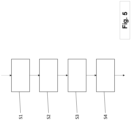
- Fig. 5 is a flow chart illustrating a method for controlling a rotational speed w of an output shaft 18 of a propulsion unit 14.
- the method comprises: S1. determining a speed setpoint value ( ⁇ s (k)), indicative of a rotational speed setpoint for said output shaft (18), and an actual speed value (w(k)), indicative of an actual rotational speed of said output shaft (18), S2.
- determining an acceleration value ⁇ ( ⁇ s (k) ⁇ ) using an acceleration value determination procedure comprising employing an acceleration conversion function ( f( ⁇ s (k), ⁇ ( k ), asm )) that uses said speed setpoint value ( ⁇ s (k)), said actual speed value (w(k)) and an acceleration setting member (asm) as inputs and which produces a resulting value ⁇ ⁇ s (k) ⁇ to be used for determining said acceleration value ( ⁇ ⁇ s ( k ) ⁇ ), said acceleration conversion function ( f ( ⁇ s ( k ), ⁇ ( k ), asm ) being such that different resulting values ( ⁇ s (k)) can be obtained for the same set of said speed setpoint value ( ⁇ s (k)) and said actual speed value (w(k)) but for different choices of said acceleration setting member (asm), S3. determining a torque request value using a torque conversion operation that uses said acceleration value ( ⁇ ⁇ s ( k ) ⁇ ),
Landscapes
- Engineering & Computer Science (AREA)
- Mechanical Engineering (AREA)
- Power Engineering (AREA)
- Transportation (AREA)
- Chemical & Material Sciences (AREA)
- Combustion & Propulsion (AREA)
- General Engineering & Computer Science (AREA)
- Control Of Vehicle Engines Or Engines For Specific Uses (AREA)
- Combined Controls Of Internal Combustion Engines (AREA)
Claims (17)
- Verfahren zum Steuern einer Drehzahl (ω) einer Ausgangswelle (18) einer Antriebseinheit (14), das Verfahren umfassend:- Bestimmen eines Drehzahlsollwertes (ωs(k)), der einen Drehzahlsollwert für die Ausgangswelle (18) angibt, und eines tatsächlichen Drehzahlwertes (ω(k)), der eine tatsächliche Drehzahl der Ausgangswelle (18) angibt,- Bestimmen eines Beschleunigungswertes (〈ω̇ s(k)〉) unter Verwendung einer Beschleunigungswertbestimmungsmethode, umfassend ein Einsetzen einer Beschleunigungsumrechnungsfunktion (f(ωs (k), ω(k),asm)), die den Geschwindigkeitssollwert (ωs(k)), den tatsächlichen Geschwindigkeitswert (ω(k)) und ein Beschleunigungseinstellelement (asm) als Eingänge verwendet und die einen resultierenden Wert (ω̇s (k)) produziert, der zum Bestimmen des Beschleunigungswertes (〈ω̇ s(k)〉) verwendet werden soll, wobei die Beschleunigungsumrechnungsfunktion (f(ωs (k), ω(k),asm)) derart ist, dass unterschiedliche resultierende Werte (ω̇s (k)) für denselben Satz des Geschwindigkeitssollwertes (ωs(k)) und des tatsächlichen Geschwindigkeitswertes (ω(k)), jedoch für unterschiedliche Optionen des Beschleunigungseinstellelements (asm) erhalten werden können,- Bestimmen eines Drehmomentanforderungswertes (Ts (k)) unter Verwendung einer Drehmomentumwandlungsoperation, die den Beschleunigungswert (〈ω̇ s(k)〉) verwendet, wobei die Drehmomentumwandlungsoperation ein Ausbilden einer Drehmomentanforderungssumme (T(k)) durch Multiplizieren des Beschleunigungswertes (〈ω̇ s(k)〉) mit einem Trägheitsmomentwert (Ĵ(k)), der ein Trägheitsmoment angibt, das der Antriebseinheit (14) zugeordnet ist, und Addieren dazu eines Widerstandsdrehmomentwertes (T̂r (k)) umfasst, der ein Widerstandsdrehmoment angibt, das der Antriebseinheit (14) zugeordnet ist, und wobei die Drehmomentumwandlungsoperation ferner das Addieren eines Drehmomentstörungswertes (T̂d (k)), der eine Drehmomentstörung angibt, die der Antriebseinheit (14) zugeordnet ist, zu der Drehmomentanforderungssumme (T(k)) umfasst, wobei der Drehmomentstörungswert (T̂d (k)) unter Verwendung von Werten bestimmt wird, die für mindestens einen vorherigen Zeitpunkt für jeden eines tatsächlichen Drehmomentwertes (Ta (k - 1)), der ein tatsächliches Drehmoment der Ausgangswelle (18) angibt, des Trägheitsmomentwertes (Ĵ(k - 1)), des Widerstandsdrehmomentwertes (T̂r (k - 1)), des Drehmomentstörungswertes (T̂d (k - 1)) und eines tatsächlichen Beschleunigungswertes (ω̇(k)) bestimmt werden, der eine tatsächliche Beschleunigung der Ausgangswelle (18) angibt, und- Steuern der Antriebseinheit (14) unter Verwendung des Drehmomentanforderungswertes.
- Verfahren nach Anspruch 1, ferner umfassend das Verwenden der Drehmomentanforderungssumme (T(k)) als den Drehmomentanforderungswert (Ts (k)).
- Verfahren nach einem der vorstehenden Ansprüche, wobei die Antriebseinheit (14) mit einem Triebstrang zum Antreiben eines Fahrzeugs (10) verbunden ist und jeder des Trägheitsmomentwertes (Ĵ(k)) und des Widerstandsdrehmomentwertes (T̂r (k)) auf der Basis von Informationen bestimmt wird, die mindestens einen aktuellen Betriebszustand des Triebstrangs angeben.
- Verfahren nach einem der vorstehenden Ansprüche, wobei das Beschleunigungseinstellelement (asm), das durch die Beschleunigungsumwandlungsfunktion (f(ωs (k), ω(k), asm)) verwendet wird, aus einem zuvor bestimmten Satz von Beschleunigungseinstellelementen (asm) stammt, der Satz umfassend mindestens zwei unterschiedliche Beschleunigungseinstellelemente (asm), vorzugsweise der Satz umfassend einen kontinuierlichen Wertebereich für das Beschleunigungseinstellelement (asm).
- Verfahren nach einem der vorstehenden Ansprüche, wobei das Verfahren ein Auswählen eines Beschleunigungseinstellelements (asm) umfasst, das durch die Beschleunigungsumwandlungsfunktion (f(ωs (k), ω(k), asm)) verwendet werden soll.
- Verfahren nach einem der vorstehenden Ansprüche, wobei die Beschleunigungswertbestimmungsmethode ferner das Bestimmen eines Überschwingvorhersagewertes (ω̇l (k)) für den Beschleunigungswert umfasst, und falls der Absolutwert des resultierenden Wertes (ω̇s (k)) den absoluten Wert des Überschwingvorhersagewertes (ω̇l (k)) überschreitet, die Beschleunigungswertbestimmungsmethode den Beschleunigungswert (〈ω̇s (k)〉) gleich dem Überschwingvorhersagewert (ω̇l (k)) einstellt, andernfalls die Beschleunigungswertbestimmungsmethode den Beschleunigungswert (〈ω̇ s(k)〉) gleich dem resultierenden Wert (ω̇s (k)) einstellt.
- Verfahren nach Anspruch 6, wobei der Überschwingvorhersagewert (ω̇l (k)) unter Verwendung von Werten bestimmt wird, die für mindestens einen vorherigen Zeitpunkt für jeden des Geschwindigkeitssollwertes (ωs (k-1)), des tatsächlichen Geschwindigkeitswertes (ω(k-1)), eines tatsächlichen Drehmomentwertes (Ta (k - 1)), der ein tatsächliches Drehmoment der Ausgangswelle (18) angibt, des Trägheitsmomentwertes (Ĵ(k - 2)), des Widerstandsdrehmomentwertes (T̂r(k - 2)) und des Drehmomentstörungswertes (T̂d (k - 2)) bestimmt werden.
- Steuereinheit (22) zum Steuern einer Drehzahl einer Ausgangswelle (18) einer Antriebseinheit (14), wobei die Steuereinheit (22) angepasst ist zum:- Empfangen von Informationen über einen Drehzahlsollwert (ω s(k)), der einen Drehzahlsollwert für die Ausgangswelle (18) angibt, und einen tatsächlichen Drehzahlwert (ω(k)), der eine tatsächliche Drehzahl der Ausgangswelle (18) angibt,- Empfangen von Informationen über ein Beschleunigungseinstellelement (asm),- Bestimmen eines Beschleunigungswertes (〈ω̇ s(k)〉) unter Verwendung einer Beschleunigungswertbestimmungsmethode, umfassend das Einsetzen einer Beschleunigungsumrechnungsfunktion (f(ωs (k), ω(k), asm)), die den Geschwindigkeitssollwert (ω̇ s(k)), den tatsächlichen Geschwindigkeitswert (ω(k)) und ein Beschleunigungseinstellglied (asm) als Eingänge verwendet und die einen resultierenden Wert (ω̇s (k)) produziert, der zum Bestimmen des Beschleunigungswertes (〈ω̇ s(k)〉) verwendet werden soll, wobei die Beschleunigungsumrechnungsfunktion (f(ωs (k), ω(k),asm)) derart ist, dass unterschiedliche resultierende Werte (ω̇s (k)) für denselben Satz des Geschwindigkeitssollwertes (ω s (k)) und des tatsächlichen Geschwindigkeitswertes (ω(k)), jedoch für unterschiedliche Optionen des Beschleunigungseinstellglieds (asm) erhalten werden können,- Bestimmen eines Drehmomentanforderungswertes (Ts (k) unter Verwendung einer Drehmomentumwandlungsoperation, die den Beschleunigungswert (〈ω̇ s(k)〉) verwendet, wobei die Drehmomentumwandlungsoperation das Ausbilden einer Drehmomentanforderungssumme (T(k)) durch Multiplizieren des Beschleunigungswertes (〈ω̇ s(k)〉) mit einem Trägheitsmomentwert (Ĵ(k)), der ein Trägheitsmoment angibt, das der Antriebseinheit (14) zugeordnet ist, und Addieren dazu eines Widerstandsdrehmomentwertes (T̂r (k)) umfasst, der ein Widerstandsdrehmoment angibt, das der Antriebseinheit (14) zugeordnet ist, und wobei die Drehmomentumwandlungsoperation ferner das Addieren eines Drehmomentstörungswertes (T̂d (k)), der die Drehmomentstörung angibt, die der Antriebseinheit (14) zugeordnet ist, zu der Drehmomentanforderungssumme (T(k)) umfasst, wobei der Drehmomentstörungswert (T̂d (k)) unter Verwendung von Werten bestimmt wird, die für mindestens einen vorherigen Zeitpunkt für jeden eines tatsächlichen Drehmomentwertes (Ta (k - 1)), der ein tatsächliches Drehmoment der Ausgangswelle (18) angibt, des Trägheitsmomentwertes (Ĵ(k - 1)), des Widerstandsdrehmomentwertes (T̂r(k - 1)), des Drehmomentstörungswertes (T̂d (k - 1)) und eines tatsächlichen Beschleunigungswertes (ω̇(k)) bestimmt werden, der eine tatsächliche Beschleunigung der Ausgangswelle (18) angibt, und- Ausgeben eines Signals, das den Drehmomentanforderungswert angibt, an die Antriebseinheit (14).
- Steuereinheit (22) nach Anspruch 8, wobei die Steuereinheit (22) angepasst ist, um die Drehmomentanforderungssumme (T(k)) als den Drehmomentanforderungswert (Ts (k)) zu verwenden.
- Steuereinheit (22) nach einem der Ansprüche 8 bis 9, wobei die Antriebseinheit (14) mit einem Triebstrang zum Antreiben eines Fahrzeugs (10) verbunden ist und jeder des Trägheitsmomentwertes (Ĵ(k)) und des Widerstandsdrehmomentwertes (T̂r (k)) auf der Basis von Informationen bestimmt wird, die mindestens einen aktuellen Betriebszustand des Triebstrangs angeben.
- Steuereinheit (22) nach einem der Ansprüche 8 bis 10, wobei das Beschleunigungseinstellelement (asm), das durch die Beschleunigungsumwandlungsfunktion (f(ωs (k), w(k), asm)) verwendet wird, aus einem zuvor bestimmten Satz von Beschleunigungseinstellelementen (asm) stammt, der Satz umfassend mindestens zwei unterschiedliche Beschleunigungseinstellelemente (asm), vorzugsweise der Satz umfassend einen kontinuierlichen Wertebereich für das Beschleunigungseinstellelement (asm).
- Steuereinheit (22) nach einem der Ansprüche 8 bis 11, wobei die Beschleunigungswertbestimmungsmethode ferner das Bestimmen eines Überschwingvorhersagewertes (ω̇l (k)) für den Beschleunigungswert (〈ω̇s (k)〉) umfasst, und falls der Absolutwert des resultierenden Wertes (ω̇s (k)) den absoluten Wert des Überschwingvorhersagewertes (ω̇l ((k)) überschreitet, die Beschleunigungswertbestimmungsmethode den Beschleunigungswert (〈ω̇ s(k)〉) gleich dem Überschwingvorhersagewert (ω̇l (k)) einstellt, andernfalls die Beschleunigungswertbestimmungsmethode den Beschleunigungswert (〈ω̇ s(k)〉) gleich dem resultierenden Wert (〈ω̇s (k〉) einstellt.
- Steuereinheit (22) nach Anspruch 12, wobei der Überschwingvorhersagewert (ω̇l (k)) unter Verwendung von Werten bestimmt wird, die für mindestens einen vorherigen Zeitpunkt für jeden des Geschwindigkeitssollwertes (ωs(k-1)), des tatsächlichen Drehzahlwertes (w(k-1)), eines tatsächlichen Drehmomentwertes (Ta (k - 1)), der ein tatsächliches Drehmoment der Ausgangswelle (18) angibt, des Trägheitsmomentwerts (Ĵ(k - 2)), des Widerstandsdrehmomentwertes (T̂r (k - 2)) und des Drehmomentstörungswertes (T̂d (k - 2)) bestimmt werden.
- Antriebsanordnung, umfassend eine Antriebseinheit (14) und eine Steuereinheit (22) nach einem der Ansprüche 8 bis 13.
- Antriebsanordnung nach Anspruch 14, wobei die Antriebsanordnung ferner eine Beschleunigungseinstellanordnung umfasst, die angepasst ist, um ein Signal zu empfangen, das eine ausgewählte Beschleunigungseinstellung angibt, und als Reaktion darauf, das Signal, das das Beschleunigungseinstellelement (asm) angibt, an die Steuereinheit (22) auszugeben.
- Fahrzeug (10), umfassend eine Steuereinheit (22) nach einem der Ansprüche 8 bis 13 oder eine Antriebsanordnung nach einem der Ansprüche 14 bis 15.
- Fahrzeug (10) nach Anspruch 16, ferner umfassend einen Triebstrang zum Antreiben des Fahrzeugs (10), wobei die Antriebseinheit (14) mit dem Triebstrang verbunden ist.
Priority Applications (3)
| Application Number | Priority Date | Filing Date | Title |
|---|---|---|---|
| EP21201095.3A EP4163486B1 (de) | 2021-10-06 | 2021-10-06 | Verfahren zur steuerung einer drehzahl einer abtriebswelle einer antriebseinheit |
| CN202211197547.6A CN115929487A (zh) | 2021-10-06 | 2022-09-29 | 用于控制推进单元的输出轴的转速的方法 |
| US17/938,144 US12384254B2 (en) | 2021-10-06 | 2022-10-05 | Method for controlling a rotational speed of an output shaft of a propulsion unit |
Applications Claiming Priority (1)
| Application Number | Priority Date | Filing Date | Title |
|---|---|---|---|
| EP21201095.3A EP4163486B1 (de) | 2021-10-06 | 2021-10-06 | Verfahren zur steuerung einer drehzahl einer abtriebswelle einer antriebseinheit |
Publications (2)
| Publication Number | Publication Date |
|---|---|
| EP4163486A1 EP4163486A1 (de) | 2023-04-12 |
| EP4163486B1 true EP4163486B1 (de) | 2025-04-02 |
Family
ID=78085486
Family Applications (1)
| Application Number | Title | Priority Date | Filing Date |
|---|---|---|---|
| EP21201095.3A Active EP4163486B1 (de) | 2021-10-06 | 2021-10-06 | Verfahren zur steuerung einer drehzahl einer abtriebswelle einer antriebseinheit |
Country Status (3)
| Country | Link |
|---|---|
| US (1) | US12384254B2 (de) |
| EP (1) | EP4163486B1 (de) |
| CN (1) | CN115929487A (de) |
Citations (1)
| Publication number | Priority date | Publication date | Assignee | Title |
|---|---|---|---|---|
| EP1580416A1 (de) * | 2004-03-24 | 2005-09-28 | Toyota Jidosha Kabushiki Kaisha | Verfahren und Vorrichtung zur Regelung der Leistung einer Brennkraftmaschine |
Family Cites Families (10)
| Publication number | Priority date | Publication date | Assignee | Title |
|---|---|---|---|---|
| US6112719A (en) * | 1998-12-15 | 2000-09-05 | Caterpillar Inc. | Acceleration based control system for speed governing |
| ITTO20010752A1 (it) * | 2001-07-27 | 2003-01-27 | Fiat Ricerche | Dispositivo e metodo di controllo della velocita' angolare di un motore. |
| US7478621B2 (en) * | 2006-04-11 | 2009-01-20 | Zf Friedrichshafen Ag | Method of compensating for engine speed overshoot |
| DE102007037037B3 (de) | 2007-08-06 | 2009-02-12 | Mtu Friedrichshafen Gmbh | Verfahren zur Regelung einer Brennkraftmaschine |
| EP2851254B1 (de) * | 2012-05-18 | 2018-09-05 | Yamaha Hatsudoki Kabushiki Kaisha | Fahrzeugsteuerungsvorrichtung und motorrad damit |
| DE102013112968A1 (de) * | 2013-11-25 | 2015-05-28 | Dr. Ing. H.C. F. Porsche Ag | Verfahren zum Steuern eines Verbrennungsmotors |
| DE102014206909A1 (de) * | 2014-04-10 | 2015-10-15 | Robert Bosch Gmbh | Verfahren zur Drehzahlregelung eines Motors |
| SE541113C2 (en) * | 2016-06-22 | 2019-04-09 | Scania Cv Ab | Method and system for controlling fuel injection in connection to engine start procedure |
| IT201800004932A1 (it) * | 2018-04-27 | 2019-10-27 | Metodo di controllo di velocita' di un motore a combustione interna | |
| JP7140299B2 (ja) * | 2020-03-06 | 2022-09-21 | 日産自動車株式会社 | 電動車両制御方法及び電動車両制御装置 |
-
2021
- 2021-10-06 EP EP21201095.3A patent/EP4163486B1/de active Active
-
2022
- 2022-09-29 CN CN202211197547.6A patent/CN115929487A/zh active Pending
- 2022-10-05 US US17/938,144 patent/US12384254B2/en active Active
Patent Citations (1)
| Publication number | Priority date | Publication date | Assignee | Title |
|---|---|---|---|---|
| EP1580416A1 (de) * | 2004-03-24 | 2005-09-28 | Toyota Jidosha Kabushiki Kaisha | Verfahren und Vorrichtung zur Regelung der Leistung einer Brennkraftmaschine |
Also Published As
| Publication number | Publication date |
|---|---|
| EP4163486A1 (de) | 2023-04-12 |
| CN115929487A (zh) | 2023-04-07 |
| US12384254B2 (en) | 2025-08-12 |
| US20230105929A1 (en) | 2023-04-06 |
Similar Documents
| Publication | Publication Date | Title |
|---|---|---|
| US7023150B2 (en) | Drive device | |
| US20100192907A1 (en) | Engine droop governor and method | |
| CN100369778C (zh) | 用于电动变速器的单电动机恢复 | |
| US20050049108A1 (en) | Engine system with cylinder number variable engine and method for controlling the engine system | |
| US8423218B2 (en) | Travel controller for industrial vehicle | |
| US10099678B2 (en) | Method of controlling hybrid electric vehicle | |
| EP2559586A2 (de) | Systeme und Verfahren zum Verbrennungsmotorlastmanagement für Fahrzeuge mit Elektroantrieb | |
| US20090132116A1 (en) | Drive system for electrically driven dump truck | |
| US20120116627A1 (en) | Engine load management for traction vehicles | |
| US20090048064A1 (en) | Drive system for electrically driven dump truck | |
| KR102322388B1 (ko) | 하이브리드 차량의 엔진 클러치 토크 추정 장치 및 방법 | |
| KR100886738B1 (ko) | 하이브리드 구동 장치와 그의 조절 방법 및 그의 엔진 제어장치, 및 컴퓨터 프로그램 리코더 | |
| US20100066277A1 (en) | Load demand and power generation balancing in direct series electric drive system | |
| EP3967542A1 (de) | Verfahren zur erzeugung eines virtuellen schwingungseffekts eines verbrennungsmotors in einem elektrofahrzeug | |
| US20040174124A1 (en) | Motor control method and system for parallel hybrid electric vehicle | |
| JP3654128B2 (ja) | 車両用制御装置 | |
| US20150300270A1 (en) | Control device of internal combustion engine, work machine and control method of internal combustion engine | |
| EP4163486B1 (de) | Verfahren zur steuerung einer drehzahl einer abtriebswelle einer antriebseinheit | |
| AU2020326438B2 (en) | Control of an engine of a machine based on detected load requirements of the machine | |
| EP1323564B1 (de) | Steuerungssystem eines Hybridfahrzeugs | |
| JP2013128344A (ja) | 制御装置、制御方法 | |
| US20200001859A1 (en) | Driving force control method and device for hybrid vehicle | |
| US20240262215A1 (en) | Methods and system for improving electric machine efficiency | |
| CN114655217B (zh) | 一种换挡方法、装置和车辆 | |
| JP2019077282A (ja) | ハイブリッド車両のクランク角度制御方法およびクランク角度制御装置 |
Legal Events
| Date | Code | Title | Description |
|---|---|---|---|
| PUAI | Public reference made under article 153(3) epc to a published international application that has entered the european phase |
Free format text: ORIGINAL CODE: 0009012 |
|
| STAA | Information on the status of an ep patent application or granted ep patent |
Free format text: STATUS: THE APPLICATION HAS BEEN PUBLISHED |
|
| AK | Designated contracting states |
Kind code of ref document: A1 Designated state(s): AL AT BE BG CH CY CZ DE DK EE ES FI FR GB GR HR HU IE IS IT LI LT LU LV MC MK MT NL NO PL PT RO RS SE SI SK SM TR |
|
| STAA | Information on the status of an ep patent application or granted ep patent |
Free format text: STATUS: REQUEST FOR EXAMINATION WAS MADE |
|
| 17P | Request for examination filed |
Effective date: 20231011 |
|
| RBV | Designated contracting states (corrected) |
Designated state(s): AL AT BE BG CH CY CZ DE DK EE ES FI FR GB GR HR HU IE IS IT LI LT LU LV MC MK MT NL NO PL PT RO RS SE SI SK SM TR |
|
| GRAP | Despatch of communication of intention to grant a patent |
Free format text: ORIGINAL CODE: EPIDOSNIGR1 |
|
| STAA | Information on the status of an ep patent application or granted ep patent |
Free format text: STATUS: GRANT OF PATENT IS INTENDED |
|
| RIC1 | Information provided on ipc code assigned before grant |
Ipc: F02D 41/14 20060101ALN20241105BHEP Ipc: F02D 31/00 20060101AFI20241105BHEP |
|
| INTG | Intention to grant announced |
Effective date: 20241114 |
|
| GRAS | Grant fee paid |
Free format text: ORIGINAL CODE: EPIDOSNIGR3 |
|
| GRAA | (expected) grant |
Free format text: ORIGINAL CODE: 0009210 |
|
| STAA | Information on the status of an ep patent application or granted ep patent |
Free format text: STATUS: THE PATENT HAS BEEN GRANTED |
|
| AK | Designated contracting states |
Kind code of ref document: B1 Designated state(s): AL AT BE BG CH CY CZ DE DK EE ES FI FR GB GR HR HU IE IS IT LI LT LU LV MC MK MT NL NO PL PT RO RS SE SI SK SM TR |
|
| REG | Reference to a national code |
Ref country code: GB Ref legal event code: FG4D |
|
| REG | Reference to a national code |
Ref country code: CH Ref legal event code: EP |
|
| REG | Reference to a national code |
Ref country code: IE Ref legal event code: FG4D |
|
| REG | Reference to a national code |
Ref country code: DE Ref legal event code: R096 Ref document number: 602021028436 Country of ref document: DE |
|
| REG | Reference to a national code |
Ref country code: NL Ref legal event code: MP Effective date: 20250402 |
|
| PG25 | Lapsed in a contracting state [announced via postgrant information from national office to epo] |
Ref country code: NL Free format text: LAPSE BECAUSE OF FAILURE TO SUBMIT A TRANSLATION OF THE DESCRIPTION OR TO PAY THE FEE WITHIN THE PRESCRIBED TIME-LIMIT Effective date: 20250402 |
|
| REG | Reference to a national code |
Ref country code: AT Ref legal event code: MK05 Ref document number: 1781470 Country of ref document: AT Kind code of ref document: T Effective date: 20250402 |
|
| PG25 | Lapsed in a contracting state [announced via postgrant information from national office to epo] |
Ref country code: FI Free format text: LAPSE BECAUSE OF FAILURE TO SUBMIT A TRANSLATION OF THE DESCRIPTION OR TO PAY THE FEE WITHIN THE PRESCRIBED TIME-LIMIT Effective date: 20250402 Ref country code: ES Free format text: LAPSE BECAUSE OF FAILURE TO SUBMIT A TRANSLATION OF THE DESCRIPTION OR TO PAY THE FEE WITHIN THE PRESCRIBED TIME-LIMIT Effective date: 20250402 Ref country code: PT Free format text: LAPSE BECAUSE OF FAILURE TO SUBMIT A TRANSLATION OF THE DESCRIPTION OR TO PAY THE FEE WITHIN THE PRESCRIBED TIME-LIMIT Effective date: 20250804 |
|
| REG | Reference to a national code |
Ref country code: LT Ref legal event code: MG9D |
|
| PG25 | Lapsed in a contracting state [announced via postgrant information from national office to epo] |
Ref country code: NO Free format text: LAPSE BECAUSE OF FAILURE TO SUBMIT A TRANSLATION OF THE DESCRIPTION OR TO PAY THE FEE WITHIN THE PRESCRIBED TIME-LIMIT Effective date: 20250702 Ref country code: GR Free format text: LAPSE BECAUSE OF FAILURE TO SUBMIT A TRANSLATION OF THE DESCRIPTION OR TO PAY THE FEE WITHIN THE PRESCRIBED TIME-LIMIT Effective date: 20250703 |
|
| PG25 | Lapsed in a contracting state [announced via postgrant information from national office to epo] |
Ref country code: PL Free format text: LAPSE BECAUSE OF FAILURE TO SUBMIT A TRANSLATION OF THE DESCRIPTION OR TO PAY THE FEE WITHIN THE PRESCRIBED TIME-LIMIT Effective date: 20250402 |
|
| PG25 | Lapsed in a contracting state [announced via postgrant information from national office to epo] |
Ref country code: BG Free format text: LAPSE BECAUSE OF FAILURE TO SUBMIT A TRANSLATION OF THE DESCRIPTION OR TO PAY THE FEE WITHIN THE PRESCRIBED TIME-LIMIT Effective date: 20250402 |
|
| PG25 | Lapsed in a contracting state [announced via postgrant information from national office to epo] |
Ref country code: HR Free format text: LAPSE BECAUSE OF FAILURE TO SUBMIT A TRANSLATION OF THE DESCRIPTION OR TO PAY THE FEE WITHIN THE PRESCRIBED TIME-LIMIT Effective date: 20250402 |
|
| PG25 | Lapsed in a contracting state [announced via postgrant information from national office to epo] |
Ref country code: AT Free format text: LAPSE BECAUSE OF FAILURE TO SUBMIT A TRANSLATION OF THE DESCRIPTION OR TO PAY THE FEE WITHIN THE PRESCRIBED TIME-LIMIT Effective date: 20250402 |
|
| PG25 | Lapsed in a contracting state [announced via postgrant information from national office to epo] |
Ref country code: RS Free format text: LAPSE BECAUSE OF FAILURE TO SUBMIT A TRANSLATION OF THE DESCRIPTION OR TO PAY THE FEE WITHIN THE PRESCRIBED TIME-LIMIT Effective date: 20250702 |
|
| PG25 | Lapsed in a contracting state [announced via postgrant information from national office to epo] |
Ref country code: IS Free format text: LAPSE BECAUSE OF FAILURE TO SUBMIT A TRANSLATION OF THE DESCRIPTION OR TO PAY THE FEE WITHIN THE PRESCRIBED TIME-LIMIT Effective date: 20250802 |
|
| PG25 | Lapsed in a contracting state [announced via postgrant information from national office to epo] |
Ref country code: LV Free format text: LAPSE BECAUSE OF FAILURE TO SUBMIT A TRANSLATION OF THE DESCRIPTION OR TO PAY THE FEE WITHIN THE PRESCRIBED TIME-LIMIT Effective date: 20250402 |
|
| REG | Reference to a national code |
Ref country code: DE Ref legal event code: R097 Ref document number: 602021028436 Country of ref document: DE |
|
| PGFP | Annual fee paid to national office [announced via postgrant information from national office to epo] |
Ref country code: DE Payment date: 20251028 Year of fee payment: 5 |
|
| PG25 | Lapsed in a contracting state [announced via postgrant information from national office to epo] |
Ref country code: DK Free format text: LAPSE BECAUSE OF FAILURE TO SUBMIT A TRANSLATION OF THE DESCRIPTION OR TO PAY THE FEE WITHIN THE PRESCRIBED TIME-LIMIT Effective date: 20250402 Ref country code: SM Free format text: LAPSE BECAUSE OF FAILURE TO SUBMIT A TRANSLATION OF THE DESCRIPTION OR TO PAY THE FEE WITHIN THE PRESCRIBED TIME-LIMIT Effective date: 20250402 |
|
| PG25 | Lapsed in a contracting state [announced via postgrant information from national office to epo] |
Ref country code: CZ Free format text: LAPSE BECAUSE OF FAILURE TO SUBMIT A TRANSLATION OF THE DESCRIPTION OR TO PAY THE FEE WITHIN THE PRESCRIBED TIME-LIMIT Effective date: 20250402 |
|
| PG25 | Lapsed in a contracting state [announced via postgrant information from national office to epo] |
Ref country code: EE Free format text: LAPSE BECAUSE OF FAILURE TO SUBMIT A TRANSLATION OF THE DESCRIPTION OR TO PAY THE FEE WITHIN THE PRESCRIBED TIME-LIMIT Effective date: 20250402 |
|
| PG25 | Lapsed in a contracting state [announced via postgrant information from national office to epo] |
Ref country code: SK Free format text: LAPSE BECAUSE OF FAILURE TO SUBMIT A TRANSLATION OF THE DESCRIPTION OR TO PAY THE FEE WITHIN THE PRESCRIBED TIME-LIMIT Effective date: 20250402 |
|
| PG25 | Lapsed in a contracting state [announced via postgrant information from national office to epo] |
Ref country code: IT Free format text: LAPSE BECAUSE OF FAILURE TO SUBMIT A TRANSLATION OF THE DESCRIPTION OR TO PAY THE FEE WITHIN THE PRESCRIBED TIME-LIMIT Effective date: 20250402 |
|
| PLBE | No opposition filed within time limit |
Free format text: ORIGINAL CODE: 0009261 |
|
| STAA | Information on the status of an ep patent application or granted ep patent |
Free format text: STATUS: NO OPPOSITION FILED WITHIN TIME LIMIT |
|
| PG25 | Lapsed in a contracting state [announced via postgrant information from national office to epo] |
Ref country code: RO Free format text: LAPSE BECAUSE OF FAILURE TO SUBMIT A TRANSLATION OF THE DESCRIPTION OR TO PAY THE FEE WITHIN THE PRESCRIBED TIME-LIMIT Effective date: 20250402 |
|
| REG | Reference to a national code |
Ref country code: CH Ref legal event code: L10 Free format text: ST27 STATUS EVENT CODE: U-0-0-L10-L00 (AS PROVIDED BY THE NATIONAL OFFICE) Effective date: 20260211 |
|
| 26N | No opposition filed |
Effective date: 20260105 |